EP3235546A1 - Damper blade with sensor - Google Patents
Damper blade with sensor Download PDFInfo
- Publication number
- EP3235546A1 EP3235546A1 EP17166555.7A EP17166555A EP3235546A1 EP 3235546 A1 EP3235546 A1 EP 3235546A1 EP 17166555 A EP17166555 A EP 17166555A EP 3235546 A1 EP3235546 A1 EP 3235546A1
- Authority
- EP
- European Patent Office
- Prior art keywords
- sensor
- damper blade
- damper
- unit
- blade
- Prior art date
- Legal status (The legal status is an assumption and is not a legal conclusion. Google has not performed a legal analysis and makes no representation as to the accuracy of the status listed.)
- Withdrawn
Links
Images

Classifications
-
- A—HUMAN NECESSITIES
- A62—LIFE-SAVING; FIRE-FIGHTING
- A62C—FIRE-FIGHTING
- A62C2/00—Fire prevention or containment
- A62C2/06—Physical fire-barriers
- A62C2/12—Hinged dampers
-
- A—HUMAN NECESSITIES
- A62—LIFE-SAVING; FIRE-FIGHTING
- A62C—FIRE-FIGHTING
- A62C2/00—Fire prevention or containment
- A62C2/06—Physical fire-barriers
- A62C2/18—Sliding dampers
-
- A—HUMAN NECESSITIES
- A62—LIFE-SAVING; FIRE-FIGHTING
- A62C—FIRE-FIGHTING
- A62C2/00—Fire prevention or containment
- A62C2/06—Physical fire-barriers
- A62C2/18—Sliding dampers
- A62C2/20—Sliding dampers at 90 degrees to the plane of the opening
-
- A—HUMAN NECESSITIES
- A62—LIFE-SAVING; FIRE-FIGHTING
- A62C—FIRE-FIGHTING
- A62C2/00—Fire prevention or containment
- A62C2/06—Physical fire-barriers
- A62C2/24—Operating or controlling mechanisms
-
- E—FIXED CONSTRUCTIONS
- E05—LOCKS; KEYS; WINDOW OR DOOR FITTINGS; SAFES
- E05F—DEVICES FOR MOVING WINGS INTO OPEN OR CLOSED POSITION; CHECKS FOR WINGS; WING FITTINGS NOT OTHERWISE PROVIDED FOR, CONCERNED WITH THE FUNCTIONING OF THE WING
- E05F15/00—Power-operated mechanisms for wings
- E05F15/70—Power-operated mechanisms for wings with automatic actuation
- E05F15/72—Power-operated mechanisms for wings with automatic actuation responsive to emergency conditions, e.g. fire
-
- F—MECHANICAL ENGINEERING; LIGHTING; HEATING; WEAPONS; BLASTING
- F24—HEATING; RANGES; VENTILATING
- F24F—AIR-CONDITIONING; AIR-HUMIDIFICATION; VENTILATION; USE OF AIR CURRENTS FOR SCREENING
- F24F13/00—Details common to, or for air-conditioning, air-humidification, ventilation or use of air currents for screening
- F24F13/08—Air-flow control members, e.g. louvres, grilles, flaps or guide plates
- F24F13/10—Air-flow control members, e.g. louvres, grilles, flaps or guide plates movable, e.g. dampers
Definitions
- the present invention belongs the technical field of dampers, such as fire dampers or smoke control dampers. It is particularly related to the field of monitoring, testing, or checking of dampers.
- Dampers with movably arranged damper blades are common and widely used in a variety of applications. Among others, they are widely used in safety-critical applications in the context of fire protection, e. g. as fire dampers and/or smoke control dampers. They are further used in large number in HVAC (Heating, Ventilation and Air Conditioning) applications.
- HVAC Heating, Ventilation and Air Conditioning
- Such checks also referred to as functional checks, include moving the damper blade into a safety position into which the damper blade is moved in case of fire and visually verifying the damper blade movement.
- Such checks accordingly require the physical presence of a trained and qualified service technician.
- many dampers are installed in locations where access is difficult and/or cumbersome. Logging or record keeping in accordance with regulatory requirements is further required for the functional checks.
- actuators such as spring-return actuators
- position switches or end switches for monitoring damper blade movements. It is to be understood, however, that such switches in fact only reflect the operation of the actuator, but not of the damper blade as such. If, for example, a drive shaft of the actuator or any other element of the actuator chain is defective, e. g. broken or unmovable due to wear, corrosion, improper assembly, or the like, an end switch or position switch may still indicate correct operation, while the damper blade does, in fact, not move at all or t least not as desired. Similarly, excessive wear or slackness may result in the unintended damper blade movements without corresponding drive movements.
- the EP2005009 discloses a device for monitoring and/or controlling the movement of a piston or piston rod of a damping or operating cylinder (movable fluidic component) in in a fluidic system.
- the device comprises an acceleration sensor which is located on or in the movable fluidic component.
- the sensor data from the acceleration sensor are transmitted to a fixed station where they are processed for monitoring/and/or controlling purposes.
- dampers that are used in fire protection applications, in particular fire dampers and smoke control dampers. Other applications, however, are not excluded.
- the damper arrangement includes a movably arranged damper blade.
- the damper blade may, for example, be movably arranged for altering an effective flow cross section of a gas conduit, such as a pipe of a fire protection system and/or smoke control system.
- the damper blade is arranged inside the gas conduit or at an inlet respectively outlet orifice of a gas conduit.
- the damper arrangement further includes a sensor unit which is rigidly attached to the damper blade.
- the sensor unit includes a sensor, the sensor being configured for generating sensor data.
- the sensor data are indicative for a position and/or a position change of the damper blade.
- the damper arrangement further includes an evaluation unit.
- the evaluation unit is configured to determine, based on the sensor data, an operational state of the damper blade.
- the sensor unit includes at least one sensor and at least two sensors may be present in some embodiments.
- the damper blade may generally be of any desired type and may in particular belong to a fire damper or a smoke control damper. Alternatively, the damper blade may also belong to a damperthat is used for controlling gas flow in a ventilation and/or HVAC system, e. g. in a building.
- the gas may, e. g. be air and/or smoke gas.
- the damper blade is arranged inside or at an inlet respectively outlet of a gas conduit such as a tube or pipe
- the gas conduit is typically tubular and of desired cross section, e. g. circular, rectangular or square.
- the damper blade is configured and arranged for a rotational or pivoting movement around a center axis.
- the damper blade may also be configured differently and/or make a different motion.
- the damper blade may, for example, also be a slider that is arranged to modify the effective flow cross section by being inserted into the gas conduit via a linear displacement movement, or some other type of movement, e. g. a slewing movement.
- the operational state of the damper blade may be or include a position and/or position change of the damper blade, and/or may be or include information that is derived from a position and/or position change of the damper blade.
- position may refer to a rotational position, linear displacement position, as well as a combination thereof.
- the damper blade is typically operatively mechanically coupled to an e. g. motoric actuator as generally known in the art, such as a servo actuator or a safety actuator, e. g. of the spring-return type.
- a motoric actuator as generally known in the art, such as a servo actuator or a safety actuator, e. g. of the spring-return type.
- Such actuator is typically arranged outside the gas conduit and coupled to the damper blade via a drive shaft.
- the actual position and/or a position change (i.e. movement) of the damper blade can be supervised and/or monitored without having direct and/or visual, access.
- the damper blade may be monitored or checked via a fully or partly automated remote monitoring and/or supervising and/or checking system.
- the sensor unit typically includes general control circuitry which may include components such as one or more microcontrollers, Application-Specific Integrated Circuits (ASICs) and other electronic circuitry as known in the art.
- the general control circuitry may control and coordinate the sensor readout and wireless communication, and may implement sensor signal conditioning, filtering and general sensor signal processing, as well as power management functions, self-diagnosis functions, and the like.
- the sensor unit may include a memory module with volatile and/or non-volatile memory for storing data, e. g. sensor data that are generated by the sensor and/or further sensors of the sensor unit, and/or data indicative of the position and or movement of the damper blade that are derived from sensor data for subsequent evaluate, process and/or interpretation by the evaluation unit.
- the sensor unit also serves as sensor data recorder respectively sensor data logger.
- the sensor unit typically includes a power supply, e. g. in form of a battery, such as a button cell battery.
- the sensor unit is a compact, self-contained device with its operational components being enclosed by a common housing.
- the sensor unit is favorably configured to operate, once it is installed, for an extended time period of typically several months up to a year or la number of years, without requiring battery replacement, maintenance, or the like. Subsequently, the sensor unit may, in dependence on its overall design, refurbished, or discarded and replaced.
- the senor is or includes at least one contactless sensor.
- the phrase "contactless sensor” means that the sensor does not rely on mechanical coupling to external elements for generating sensor data.
- the contactless sensor is a solid-state sensor without moving elements and/or is a micro machined sensor.
- the sensor may be a single sensor for a single variable or may be a combined sensor that is sensitive for a number of variables and/or may be a combined sensor as a combination of more than one individual sensors.
- the senor is used for determining an operational state of the damper blade, as it is required for monitoring, checking and testing purposes. Due to the rigid mechanical coupling between damper blade and sensor unit, the sensor data reflect the actual operational state of the damper blade, e. g. a damper blade position and/or position change, rather than relying on sensors at the drive-side of the actuator chain, such as encoders, end switches or position switches of an actuator. Therefore, determining an operational state of the damper blade in accordance with the present invention is virtually equivalent to a direct visual inspection of the damper blade and may accordingly replace the same. In principle, sensors at the drive-side of the actuator chain are not required and may be omitted. They may, however, be present, e. g. for redundancy and/or verification purposes.
- the evaluation unit is typically based on a microcomputer or microcontroller with corresponding firmware and/or software code, but may also include other components as generally known in the art, such as one or more Application Specific Integrated Circuits (ASICs), general purpose electronics, and the like.
- ASICs Application Specific Integrated Circuits
- the evaluation unit is configured to evaluate, process and/or interpret the sensor data.
- the evaluation unit may be a compact, self-contained unit that is typically arranged outside the gas conduit, e. g. next to an actuator.
- the evaluation unit may be distributed and be realized by a number of different modules that may also be distributed.
- the evaluation unit is, fully or partly, realized integral with respectively as part of the actuator, a control unit for the actuator, an overall building management system, control and indicating equipment, or the like.
- the evaluation unit may be a typically computerized device with one or more microcontrollers, microcontrollers, ASICs, or the like.
- the senor unit is configured to operate continuously and the senor generates data on a continuous basis.
- the processing unit may be configured to continuously process the sensor data.
- the sensor data may be stored in memory as mentioned before and processed, e. g., on demand.
- the sensor unit is configured to generally operate in a standby mode of low and favorably negligible power consumption and is activated and switched to an active mode where sensor data are stored, processed, and/or transmitted to other devices as explained blow only by an activation trigger.
- activation trigger may be generated by the sensor unit itself.
- the sensor unit may, in the standby mode, monitor the sensor data that are generated by the sensor on a continuous basis and may detect, based on the data, an event that is indicative for a damper blade movement and/or generally an event of interest. In such an event, an activation trigger may be generated.
- the monitoring for events of interest may be carried out with substantially less power consumption as compared to full operation of the sensor unit.
- the sensor unit may be configured to receive an activation trigger from another device via a wireless sensor unit communication module as explained in more detail below.
- the sensor unit is hermetical sealed.
- a hermetical sealed sensor unit is fully enclosed and designed to withstand and operate under adverse conditions that may be present in the gas conduit, such as comparatively warm or cold temperature, high or low air humidity, the presence of smoke gas, and the like.
- the sensor unit is coupled to the damper blade by gluing.
- This type of embodiment is advantageous because it enables comparatively simple attachment. Furthermore, no modification is required for typical dampers and damper blades. This is particularly favorable because some types of dampers, in particular fire dampers, are subject to timely, complex and costly regulatory certification or approval procedures. Furthermore, the same type of damper may accordingly be equipped with or without sensor unit as desired. Furthermore, an existing damper may be easily upgraded by attaching a sensor unit. Attaching by gluing may, e.g., be done via two-part adhesive or double-sided adhesive tape. The sensor unit may be attached to the damper blade additionally or alternatively by other means, such as screwing.
- the sensor unit includes a wireless sensor unit communication module, the sensor unit being configured to transmit the sensor data via the sensor unit communication module.
- the evaluation unit includes an evaluation unit communication module and is configured to receive the sensor data via the evaluation unit communication module.
- the wireless sensor unit communication module and the wireless evaluation unit communication module are configured for communication with each other and are typically Radio Frequency (RF) communication units in accordance with known general purpose standards and protocols, such as the Bluetooth standard, or may be proprietary.
- the evaluation unit communication module is generally arranged outside the gas conduit, e. g. at or close to the actuator or somewhat remote. The communication range is chosen accordingly and may, e. g. be in a typical range of 0.3 meter to 2 meter.
- the wireless sensor unit communication module may be of the sender or transmitter type only, while the wireless evaluation unit communication module may be of the receivertype only, thus enabling unidirectional data transmission from the sensor unit to the evaluation unit.
- the wireless sensor unit communication module and favorably the wireless evaluation unit communication module may be configured for bidirectional communication.
- Such embodiment is advantageous since it allows the transmission of data from the evaluation unit or a further device to the sensor unit, which is useful, e. g. for configuring the sensor unit and/or for diagnosis purposes.
- At least the evaluation unit communication module is permanently installed within the communication range with the sensor unit communication module. Further modules of the evaluation module may also be permanently installed and present, being it in a common integral unit with the evaluation unit communication module, or separate.
- Such a setup is favorable for supervising, monitoring, checking, and/or testing the damper at any desired time, without requiring physical access or installation.
- Such setup may especially be favorably used in the framework of an automated checking scheme for routinely testing of dampers.
- the evaluation unit may not be permanently installed but is only temporarily present, e. g. for damper service purposes.
- the monitoring unit may, be a dedicated device and/or a general purpose computing device, e. g. a personal computer (PC), laptop or tablet computer, or smartphone.
- the evaluation unit communication module is permanently installed, while other modules of the evaluation unit are only present when required, e. g. for service purposes, and are operatively coupled to the evaluation unit communication module, e. g. via a LAN, WLAN or fieldbus network, and/or via the internet.
- the evaluation unit is arranged outside the gas conduit and where the sensor unit and processing unit communicate via respective communication modules is favorable undertypical circumstances and is assumed in the following, where not explicitly stated differently. Dependent on the specific situation, however, other arrangements and architectures may also be used.
- the processing unit may be fully or partly included in the sensor unit and may transmitted partly or fully processed data to a remote device and remote unit.
- the sensor unit and evaluation unit communicate and exchange data and/or signals via wired communication rather than via wireless communication interfaces.
- the sensor unit communication module and the evaluation unit communication unit may be designed for wired communication.
- the sensor unit and the evaluation unit are configured to temporarily couple via wired or wireless connection, e. g. Near Field Communication (NFC) or infrared (IR) communication on demand for data communication respectively sensor data transmission to the evaluation module.
- NFC Near Field Communication
- IR infrared
- a separate interface device is present and the sensor data are transmitted via wired or wireless connection to the interface device and from the interface device to the evaluation unit.
- the interface device may, e. g., be a Smart Phone, a Tablet or Laptop PC, or the like.
- the senor is or includes at least one of an acceleration sensor and a gyroscopic sensor.
- the damper blade position can be calculated from the acceleration and/or tilting respectively rotation as known in the art.
- Typical acceleration sensors and/or gyroscopic sensors are micro machined respectively MEMS (Micro Electro Mechanical Systems).Gyroscopic sensors and acceleration sensors are favorable examples for contactless sensors in the context of the present disclosure.
- an acceleration sensor is designed to determine acceleration along at least two different measurement axes.
- the sensor is typically a two-axis-sensor or a three-axis sensor with the two respectively three axes typically being orthogonal.
- a gyroscopic sensor may be designed to determine tilting respectively rotation acceleration around at least two different measurement axes.
- a gyroscopic sensor may especially be designed for determining tilting respectively rotation around three orthogonal axes.
- a distance sensor that is configured to measure, e. g., a distance to a reference point, such as a reference point of an inner surface of the gas conduit.
- the sensor may be or include a contactless encoder, e. g. a rotational optical encoder measures a rotational position and/or rotational position change of the center axis
- the sensor unit further includes at least one of a temperature sensor, a gas sensor, a carbonic oxides (CO) sensor, a nitrogen oxides (NOx), a volatile organic components (VOC) sensor, an artificial nose, a smoke sensor, a multi gas sensor, a pressure sensor, and a humidity sensor.
- a temperature sensor may be used in addition or alternatively to further sensor, such as an acceleration sensor or gyroscopic sensor, for determining the position and/or position change of the damper blade.
- an air flow may be generated inside the gas conduit via a fan or blower.
- the damper blade will shield the sensor unit and accordingly the temperature sensor to a variable degree in dependence of the damper blade position, thus altering the temperature that is measured by the temperature sensor.
- a pressure sensor and/or a flow sensor may be used for determining the position and/or position change of the damper blade. If an air flow is generated inside the gas conduit as explained before, the dynamic pressure that is measured by a pressure sensor that is hit by the air flow will increase with the blade being moved towards the closed position. Similarly, the air flow across the blade is continuously reduced as the blade moves towards a closed position (where it is ideally zero) and increased as the blade moves toward the opened position (where it assumes a maximum).
- a temperature sensor may be used for detecting a raise of temperature inside the gas conduit, thus serving as early fire detector which may detect a fire earlier than conventional fire detectors based on room temperature measurement, fusible link sensors, and the like.
- gas and/or smoke sensors such as a oxide gas (CO) sensor, a nitrogen oxides (NOx) sensor, a volatile organic components (VOC) sensor may be present and used for early detection of fire and/or further safety critical situations.
- Further sensors, in particular contactless sensors that may also be present are general environmental sensors, such as a pressure sensor and/or a humidity sensor.
- the sensor unit is configured to detect an indication of a case of fire, and to provide a fire alarm signal in this case.
- the sensor unit and/or the evaluation unit may further be configured to control an actuator to move the blade into a safety position in this case.
- the sensor unit includes an optical sensor, in particular a camera module and/or an optical fire detector.
- a camera module may be arranged to capture an image of the inside of the gas conduit and may in particular be sensible in the visible and/or infrared range.
- still and/or video images that are captured by the camera module may be evaluated manually and/are automatically in order to check the general conditions inside the gas conduit and in particular to check for the potential presence of dirt, stain, and the like.
- the captured image or images may be transmitted to the evaluation unit and/or a further device or unit for evaluation purposes. In an embodiment, such unit is configured for automatic image analysis.
- Both a camera module as well as other sensors, in particular a temperature sensor, a pressure sensor and/or a flow sensor as mentioned before may accordingly serve as remote inspection sensor for a remote inspection (i. e. without direct and in particular visual access) of the blade arrangement in the context of a functional check, on demand at any desired point in time, or continuously.
- the optional camera unit may be used as fire detecting sensor in particular by optically detecting the smoke the generally associated with a fire.
- another type of optical fire detector is generally known in the art may be provided for (early) fire detection.
- the sensor unit itself is favorably configured detect the fire via sensor data analysis respectively image analysis and to generate, in the case of fire, a corresponding fire alarm signal and to transmit this fire alarm signal to the evaluation unit and/or a fire alarm system.
- the sensor unit and/or the evaluation unit may accordingly serve as fire detection unit.
- the detection may alternatively or additionally also be carried out by a further device or unit, such as the fire alarm system, which may be configured accordingly.
- the sensor unit may be considered as functional part of a fire alarm system, fire detection system or control system.
- one or more sensors of the sensor unit may further serve as environmental condition sensors in the context of air-conditioning control.
- the sensor unit may be configured for wired and/or wireless communication with an air conditioning system directly and/or via the evaluation unit.
- the blade arrangement and in particular the sensor unit may be considered as functional part of an air conditioning system.
- determining the operational state of the damper blade includes determining whetherthe damper blade has assumed and/or is in a reference position, in particular a fully opened or a fully closed position.
- the evaluation unit may accordingly be configured to determine the operational state of the damper blade by determining whether the damper blade has assumed and/or is in a reference position, in particular a fully opened or a fully closed position.
- a reference position may be a safety position.
- a reference position is an end position that is assumed by the damper blade at the beginning and/or the end of a movement.
- a fully closed position may be a safety position into which the damper blade is moved in case of fire may be a reference position.
- a fully opened position may be a safety position and serve as reference position.
- determining the operational state of the damper blade includes comparing whether an actual position of the damper blade corresponds to an expected position of the damper blade.
- the evaluation unit may be configured to determine the operational state of the damper blade by comparing whether an actual position of the damper blade correspondsto an expected position of the damper blade.
- the expected position may be any desired position that can be assumed by the damper blade. It may, for example, be a reference position as explained before. It may also be a position that is assumed by the damper blade during its movement between two end positions.
- the expected position is given as a function or as a sequence of positions in dependence of the time or another independent variable, e. g. a rotational position of the drive shaft.
- the sensor unit may transmit the sensor data in real time to the processing unit during a damper blade movement as explained above.
- the sensor data may be evaluated by the evaluation unit in real time.
- the sensor data may be generated and stored in real time by memory of the sensor unit and transmitted to and evaluated by the evaluation unit subsequent to the damper blade movement.
- the evaluation unit is configured to determine, based on the sensor data and/or data derived from the sensor data, whether or not the damper arrangement and/or the damper blade has passed or failed a functional check.
- the damper arrangement includes an actuator, the actuator being operatively coupled with the damper blade for adjusting the position of the damper blade.
- the actuator is typically arranged outside the gas conduit.
- the actuator is typically an electric actuator with a motor, but may also be, e. g., a hydraulic or pneumatic actuator.
- the actuator is a servo actuator as generally known in the art.
- the actuator may especially be a safety actuator, e. g. a spring-return actuator that keeps the damper blade in a standard position, e. g.
- the damper is a smoke control damper
- the standard position may be a fully closed position and the safety position may be a fully opened position.
- any other damper blade position may serve as standard position.
- the standard position may vary over time.
- the damper blade is moved into a reference position (e. g. a safety position) for checking purposes. As part of the checking or after the checking, the damper blade is typically moved back into the previous standard position.
- the damper arrangement includes a control unit, the control unit being configured to control operation of the actuator.
- the control unit may especially be configured to control the actuator to move the damper blade from an initial position, e. g. a standard position as explained before, into a reference position.
- the control unit may be designed to selectively and reversibly connect respectively disconnect a motor and a power supply by way of a relay, solid state switch or the like. Disconnecting the motor from the power supply results in a spring-driven damper blade movement into the safety position as reference position.
- the control unit may further be configured to control the actuator to move the damper blade, after moving the damper blade into the reference position, back into the initial position.
- control unit may be designed to control the actuator to move and maintain the damper blade in a desired set position by way of closed or open loop control, as generally known in the art.
- control unit is a switch or button for interrupting the actuator power supply.
- control unit may be configured to move the damper blade into a defined reference position or safety position in case of a safety-critical situation, such as a fire, being detected at some location of a building, in accordance with overall safety and fire control procedures.
- control unit may be operatively connected to or be part of a fire protection system as typically present and/or required in larger or public buildings.
- At least one fusible link fire detector is typically present.
- the at least one fusible link interrupts the actuator power supply in case of fire, thus ensuring an immediate movement into the safety position.
- Fusible link fire detectors may also be connected to and/or part of the control unit.
- a sequence of moving the damper blade from an initial position into a reference position, in particular a safety position, and back into the initial position, and evaluating an operational state of the damper blade for the movement into the reference position and optionally back into the initial position is also referred to as functional check.
- determining whether the reference position and optionally the initial position are correctly assumed by the damper blade may be carried out manually by way of evaluating the sensor data respectively data that are derived from the sensor data, such as a measured position-time curve. Alternatively, such determination may be done automatically, e. g. by the evaluation unit.
- a functional check may be initiated manually by an operator. Alternatively, it may be initiated as part of an automated checking scheme that is initiated by the control unit and/or a further fire alarm system or overall building management system or control and indicating equipment.
- the checking scheme may include initiating a testing procedure e. g. once a day, once a week, once a month or once every six months.
- control unit is configured to move the damper blade into the reference position and optionally back into an initial position repeatedly, in particular periodically, according to a checking scheme.
- Each movement of the damper blade into the reference position belongs to a functional check.
- an operational state of the damper blade may be evaluated.
- the present disclosure is directed towards a method for monitoring a movable damper blade respectively a damper checking method.
- the damper blade may be movably arranged such that moving the damper blade inside the gas conduit alters an effective flow cross section of a gas conduit.
- the method includes generating, via a sensor of a sensor unit that is rigidly mechanically attached to the damper blade inside the gas conduit, sensor data indicative for the position and/or position change of the damper blade.
- the method further includes determining, based on the sensor data, an operational state of the damper blade.
- the sensor data is or includes acceleration data.
- the method includes wirelessly transmitting the sensor data from the sensor to an evaluation unit, wherein the determining of the operational state of the damper blade is executed by the evaluation unit.
- the method may include a wired transmission of the sensor data.
- the method includes controlling an actuatorto move the damper blade into a reference position, in particular a fully opened or a fully closed position.
- the method may further include determining whether the damper blade has assumed and/or is in the reference position, and/or determining, whether an actual position of the damper blade corresponds to an expected position of the damper blade.
- the method may further include controlling the actuatorto subsequently move the damper blade back from the reference position into the initial position.
- Such method may optionally further include determining whether the damper blade has assumed and/or is in the initial position.
- the method may include carrying out such steps repeatedly according to a checking scheme as explained before as well as further below in context of exemplary embodiments.
- the method includes determining, based on the determined operational state of the damper blade, whether a functional check of the damper blade and/or of a damper arrangement that includes the damper blade, is passed, and outputting the result of the determination. These steps may especially be carried out automatically by the evaluation unit which may be configured accordingly.
- the method may include outputting the generated sensor data and/or data that are derived from the sensor data.
- the method may in particular include recording whether the damper blade has correctly assumed and/or is in the initial position, a value of the initial position and/or reference position, a damper blade as position of time, and/or the time required for the damper blade to move between the initial position and the reference position.
- Outputting the result may in particular be done by storing into a log-file and/or a printout, favorably in accordance with applicable regulatory requirements.
- the storing or logging may for example be done in the sensor unit, the evaluation unit, the actuator unit, a remote device, such as a server, and/or a cloud.
- the sensors of the sensor unit may also be used for general remote inspection purposes in addition or alternatively to the before-described functional checks.
- the results of such remote inspections may be logged or stored in the same way, e. g. via a log-file and/or a printout, including a storing in the sensor unit, in the evaluation unit, the actuator unit, a remote device, such as a server, and/or a cloud.
- the data transmission, in particular to a remote device may optionally include an internet-based data transmission.
- Determining whether or not the functional check is passed or failed may include or be carried out by comparing one or more sensor data and/or data derived from the sensor data as explained before with appropriate reference or threshold values as checking criteria.
- a method for monitoring a damper blade in accordance with the present disclosure may be carried out with a damper arrangement according to the present disclosure. Therefore, disclosed embodiments of a damper arrangement also disclose corresponding methods of a method for monitoring a damper blade. Likewise, embodiments of a method for monitoring a damper blade also disclose corresponding embodiments of a damper arrangement.
- the present disclosure is directed towards a further damper arrangement, comprising a movably arranged damper blade and a sensor unit.
- the sensor unit is rigidly attached to the damper blade and includes a sensor configured to generate sensor data that are indicative a fire.
- the damper arrangement may further include a fire detection unit.
- the fire detection unit may be configured to determine, based on the sensor data, the presence of a case of fire.
- the sensor of such damper arrangement may be any sensor as discussed in the context of fire detection above, such as a temperature sensor, smoke gas sensor, the camera module, or a combination thereof.
- the fire detection unit is configured to generate a fire alarm signal if a (potential) case of fire is detected and to transmit the fire alarm signal to further devices and/or units, such as a fire control system.
- This type of damper arrangement may further include the above discussed modules, in particular wired or wireless communication modules.
- the present disclosure is directed towards a method for detecting a case of fire.
- the method includes providing a damper arrangement as discussed before.
- the method further includes detecting the presence of a case of fire and generating a fire alarm signal if a case of fire is detected.
- the method includes, if a case of fire is detected, establishing a preferably wireless communication link and transmitting the fire alarm signal via the communication link.
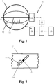
- the damper arrangement 1 includes a damper blade 10, a sensor unit 11, an evaluation unit 12, an actuator 13 and a control unit 14.
- the damper blade 10 is arranged inside or at an inlet or outlet end of a gas conduit 2.
- the gas conduit 2 is pipe-shaped and of circular cross section.
- the damper blade 10 substantially has the shape of a circular disc and is dimensioned to tightly fit into the opening of the gas conduit 2.
- the damper blade 10 is rotatable arranged around a pivoting axis A that runs through the damper blade center, i.e. is arranged along a diameter of the damper blade 10.
- actuator 13 is arranged and mechanically coupled with the damper blade 10 via a drive shaft for pivoting the damper blade 10 about the pivoting axis A.
- the actuator 13 is a spring-return actuator.
- the damper blade 10 may, as such, be a standard damper blade according to the state of the art that may also be used without the sensor unit 11.
- the sensor unit 11 is adhesively mounted on or attached to the damper blade 10.
- a housing surface of the sensor unit 11 is realized as flat adhesive-coated mounting surface.
- the damper blade 10 and the sensor unit 11 form common rigid mechanical assembly.
- the sensor unit 11 and the evaluation unit 1 2 are arranged to operatively couple and wirelessly exchange data.
- the wireless connection is a Bluetooth Low Energy connection.
- a functional check may be carried out under control of the control unit 14 as discussed in more detail further below.
- the control unit 14 is configured to selectively interrupt the power supply of the actuator 13, thus initiating a movement of the damper blade 10 into the reference position as explained before.
- an optional additional fusible link fire detector 15 is present in order to ensure that the power supply of actuator 13 is in any case interrupted in case of fire, independent of the control unit 14.
- the fusible link fire detector 14 may also be regarded as functional part of the control unit 14.
- Fig. 1 further shows an optional remote device 16 in operational coupling with the sensor evaluation unit 14.
- the optional remote device 16 may, for example, be an external computer, a building management system, a server, or a cloud-based storage.
- the operational coupling may be based on wired and/or wireless communication, including general purpose mobile communication networks, such as cell phone communication networks, and the internet.
- measured sensor data as discussed further below, such as position and/or position data of the blade 10, as well as the results of functional checks and/or remote inspection results may be stored.
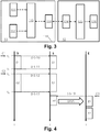
- Fig. 3 showing, in combination, an embodiment of the sensor unit 11 and the evaluation unit 12 as well as their interaction in a schematic functional view.
- the sensor unit 11 is a sensor data logger.
- the functional components of the sensor unit 11 are enclosed by and encapsulated inside a housing 110.
- a contactless sensor of the sensor unit 11 is realized by a three-axis MEMS acceleration sensor or gyroscopic sensor 111.
- a temperature sensor 112 is additionally provided. Both sensors 111, 112 are operatively coupled to a sensor unit central module 113 directly and/or via interface circuitry as required.
- the sensors 111, 112 may include integrated interface circuitry, such as filtering and/or analogue-to-digital-conversion circuitry. Alternatively or additionally, other sensors may be present, e. g.
- a barometric pressure sensor, a humidity sensor, and/or the sensors 111, 112 may be or include such sensors.
- One or more sensors may be integrated into a single unit, e. g. a single MEMS.
- the sensor unit central module 113 is further operatively coupled to the sensor unit communication module 114, e. g. a Bluetooth Low Energy module as explained before.
- the sensor unit 11 is powered by an integrated power supply, e. g. a button-type battery.
- the optional sensor 112 may further be or include another sensor or a number of sensors as mentioned in the general description, such as the smoke gas sensor, a pressure sensor, a humidity sensor, and/or a camera module.
- the sensor unit central module 113 is typically based on a microcomputer, microcontroller and/or an Application Specific Integrated Circuit (ASIC) and is designed for controlling the overall function of the sensor unit 11 as well as for storing sensor data from sensors 111, 112 directly or in pre-processed form in an internal writable memory.
- the sensor unit central module 113 accordingly serves as memory module.
- the memory module may also be separate.
- the sensor unit 11 is designed to generally operate in a low-energy mode or standby mode.
- the sensors 111, 112 are active and capture or measure data on a continuous or quasi-continuous basis.
- the sensor unit central module 113 is configured to continuously monitor the sensor data for the occurrence of an event of interest. If an event of interest is detected, the sensor unit 11 is switched into a recording mode where the sensor data are stored in the internal memory of the sensor unit central module 113 respectively a memory module in a virtually continuous way. After the event of interest, the sensor unit 11 may switch back into the low-energy mode.
- An event of interest is an event that shall be evaluated for determining an operational state of the damper blade 10.
- An event of interest may especially be a damper blade movement and is reflected in the sensor signal by the occurrence of a signal, e.g. an acceleration signal, that exceeds potential sensor noise, and/or by a signal change over time, e. g. a comparatively quick temperature change as it results from a change in the air/gas flow that is associated with a damper blade movement, or a directional change of the gravity vector as resulting from the damper blade 10 pivoting around pivoting axis A.
- a signal e.g. an acceleration signal
- a signal change over time e.g. a comparatively quick temperature change as it results from a change in the air/gas flow that is associated with a damper blade movement, or a directional change of the gravity vector as resulting from the damper blade 10 pivoting around pivoting axis A.
- the evaluation unit 12 includes an evaluation unit communication module 124, an evaluation unit central module 123, and an evaluation unit output module 126.
- the evaluation unit central module 123 is configured to process and/or evaluate the sensor data as received via the evaluation unit communication module 124 and to compute, based on the sensor data, operational state information regarding the damper blade 10.
- the operational state information is provided directly and/or in processed form to the evaluation unit output module 126, e. g. a display, of the evaluation unit 12.
- the evaluation unit output module 126 may further include a remote device communication interface for operative coupling with a remote device 16 as explained before.
- At least the evaluation unit communication module 124 is permanently arranged within the communication range of the sensor unit communication module 114, e.g. next to or integral with the actuator 13.
- the other modules of the evaluation unit 12 may, e. g. arranged remotely and, e. g. be integral with the control unit 13. This type of architecture, however, is not essential and other architectures may be used as well.
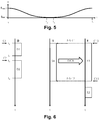
- Fig. 4 illustrating an exemplary method for monitoring the damper blade 10 in a testing procedure in a schematic timing diagram.
- the testing procedure establishes a functional check of the damper arrangement 1.
- the method may be carried out with a damper arrangement according to Fig. 1 to Fig. 3
- the left timeline refers to the damper blade 10 and the actuator 13
- the middle timeline refers to the sensor unit 11
- the right timeline refers to the evaluation unit 12.
- Activities are indicated by labelled boxes next to the corresponding timeline, with the upper respectively lower edge of a box indicating the beginning and ending of an activity.
- a box labelled “D” accordingly indicates a movement of the actuator 13 respectively damper blade 10;
- a box labelled “S” indicates an operation of the sensor unit 11, and
- a box labelled “E” indicates an operation performed by the evaluation unit 12.
- Dashed arrows between boxes indicate if an action by one of (D, S, E) triggers or initiates an activity of another of (D, S, E).
- the method in form of a testing procedure is carried out under control of the control unit 14.
- the testing procedure may be specifically initiated by a user or operator, or may additionally or alternatively be carried out automatically, e. g. every month or every six months according to a checking scheme.
- the actuator 13 is further a spring-return actuator as explained before. Control signals are indicated by "C".
- the damper blade 10 is, at the beginning of the testing procedure, in a standard position as initial position.
- the initial position may, e. g. be a fully opened position. Any other initial position, however, is possible as well, in dependence of the actuator 13 and the control unit 14.
- the testing procedure starts by the controller 14 interrupting the power supply of the actuator 13 (C1), thus initiating a movement of the damper blade 10 from the initial position into the reference position (D1).
- the reference position is a fully closed safety position.
- the damper blade 10 may be maintained in the reference position for some time.
- the controller 14 restores the power supply of actuator 13 (C2), thus initiating a movement of the damper blade 10 back into the initial position (D2).
- Providing the control signals (C1, C2) may be time-controlled.
- the movements of the damper blade 10 from the initial position into the reference position and back into the initial position are events of interest for the sensor unit 11.
- the sensor unit 11 Before the damper blade movement starts, the sensor unit 11 is in the low energy mode where sensor signals are monitored, but no storing or recording of the generated data is carried out.
- the start of the damper blade movements (D1, D2) is detected by the sensor unit 11 and accordinglytriggers (D-S-10, D-S-12)the beginning of the sensor data recording (S1, S2).
- the end of the damper blade movement is detected and triggers (D-S-11, D-S-13) the end the sensor data recording (S1, S2).
- the sensor unit 11 stores sensor data that are generated during the damper blade movement continuously and favorably with time stamps or time indices that are generated by the sensor unit 11, e. g. in a real time clock of the sensor unit central module 113.
- the movements of damper blade 10 into the reference position (D1) and back into the initial position (D2) are stored by the sensor unit 11 as two separate events of interest.
- the time between the two damper blade movements and the moving speed may also be commonly stored as single event of interest.
- the control unit 14 sends a control signal (C3) to the evaluation unit 12.
- the evaluation unit 12 accordingly initiates the establishment of a communication channel between the evaluation unit 12 and the sensor unit 11 (E-S-10), and the stored data are read out respectively transferred to the evaluation unit 12 via the wireless sensor unit communication module 114 and the wireless evaluation unit communication module 124, (S3, E1). After the data transfer, the stored sensor data may be deleted in the sensor unit 11.
- a temporary communication link is initiated and data transmission is requested by the evaluation unit 1 2.
- the sensor unit 11 and the evaluation unit 12 accordingly operate in a pull configuration. This configuration, however, is not essential and a push configuration may be used instead.
- the operational state of the damper blade 10 that is considered is its (rotational) position as a function of time and is computed by the evaluation unit central module 123 from the sensor data originating from acceleration sensor or gyroscopic sensor 111, but may similarly or additionally also origin from other sensors.
- FIG. 5 schematically showing the computed (rotational) position as operational state of the damper blade 10, indicated by angle ⁇ , as a function of time t.
- a graph corresponding to Fig. 5 may be displayed on the monitoring output unit 126.
- the damper blade 10 operates correctly and moves smoothly between the initial position (rotational angle ⁇ max ) and the reference position (rotational angle ⁇ min ) in both directions. If, for example, the mechanic coupling between damper 10 and the actuator 13 was broken, no or only very little damper blade movement would be visible in the graph. Similarly, an undesired stop of the damper blade would be reflected by the rotational angle ⁇ not reaching the maximum angle ⁇ max respectively minimum angle ⁇ min . Further abnormalities in the damper blade movement, e. g. a temporary jamming, are also reflected by abnormalities respectively distortions in the graph.
- a temporary jamming are also reflected by abnormalities respectively distortions in the graph.
- the evaluation unit 12 may be configured to only display the graph and leave the interpretation, i.e. the decision whether or not the damper blade 10 and the actuator 13 are healthy and operating correctly, to an (expert) user.
- the evaluation unit 12 may be configured to automatically evaluate the stored sensor data. It may, for example, determine whether and in what time the maximum angle ⁇ max respectively minimum angle ⁇ min as expected positions are correctly reached. This is particularly favorable in context of an automated checking scheme.
- the data may be compared with corresponding reference or threshold values to decide on pass or fail of a functional check automatically or manually.
- the evaluation unit 12 is configured to evaluate the angle-versus-time-curve ( Fig. 5 ) and determine whether the measured curve fits to an expected curve, using numerical algorithms.
- an expected positions of the damper blade 10 is given for each point in time by the reference curve, while the measured position gives the actual position of the damper blade 10.
- record keeping of the test result may, e. g., be done manually or the (expert user) may confirm correctness of the damper operation, i. e. passing respectively failing of the test, e. g. via a corresponding data entry and a corresponding record or log may be generated, e.g. by the evaluation unit 12 or a further device.
- passing or failing of the test may be determined automatically and outputted into a log-file and/or to a printer.
- the data that are outputted may include data such as time and date of the test, but may also comprise data that are derived from the sensor data, such as the time required for the damper movements, the damper position in the initial and/or reference position, a position-versus-time graph of the damper position ( Fig. 5 ), or the like.
- the result of the functional check, the sensor data and/or data that are derived from the sensor data may further be outputted to and stored by the remote device 16. Alternatively or additionally, the data may be logged and/or stored by the sensor unit 12, the actuator 13 and/orthe evaluation unit 12.
- the sensor unit 11 is, for this type of embodiment, configured to record any damper blade movement as event of interest. If a damper blade movement occurs at some point of time before a testing procedure according to Fig. 4 is carried out respectively between two consecutive testing procedures, such damper blade movement may be recorded and read out along with the data of the next following testing procedure (S3, E1 in Fig. 4 ). Thereby, it may be determined manually and/or via the evaluation unit 12, if any damper blade movements, in particular unintended damper blade movements, have occurred. Such unintended damper blade movements may result, e. g., from mechanical slackness or a loose contact or general electrical fault in the power supply or control of actuator 13.
- a testing procedure may comprise of exposing the damper blade 10 in a given position to an air stream that is generated by a fan or blower and determining the damper blade movement due to, e. g. slackness.
- Fig. 6 illustrating a method for monitoring a damper blade or procedure for testing a damper blade 10 according to a further exemplary embodiment.
- the damper arrangement also follows Fig. 1 to Fig. 3 . Operation of the sensor unit 11 and the evaluation unit 12 as well as their interaction, however, is somewhat different.
- the sensor unit 11 does not automatically detect the start and end of the damper blade movements (D1, D2), but start and stop of the data acquisition is initiated via explicit commands (E-S-11, E-S-1 2) that are transmitted from the evaluation unit 12 to the sensor unit 11.
- the senor data are transmitted from the sensor unit 11 to the evaluation unit 12 and stored by the evaluation unit (S4, E3).
- the control unit 14 sends, along with interrupting the power supply of actuator 13 (C1) a trigger signal (C10) to the evaluation unit 12, which, in turn, commands the sensor unit 11 to start data acquisition (E-R-11).
- the control unit 14 sends, after the damper blade 10 returning into the initial position, a trigger signal (C11) to the evaluation unit 12, which, in turn, commands the sensor unit 11 to stop data acquisition (E-R-1 2).
- the total acquisition time i.e. the time between commands (C10, C11) is time-controlled by the control unit 12.
- the acquisition time is favorably somewhat longer than the total movement time of the damper blade 10, i.e. the time span from t 1 to t 4 .
- Fig. 7 illustrating part of an exemplary testing procedure for testing a damper blade 10 according to a further embodiment.
- the damper arrangement also follows Fig. 1 to Fig. 3 . Operation of the sensor unit 11 and the evaluation unit 12 as well as their interaction, however, is somewhat different. In Fig. 7 , only the movement of damper blade 10 from the initial position into the reference position is shown.
- the sensor unit 11 operates similar to the embodiment as discussed before with reference of Fig. 4 in so far as start and end of a damper blade movement as event of interest is automatically detected and data recording is automatically started and stopped accordingly.
- the sensor unit 11 is configured, after stopping data recording, to establish a communication with the evaluation unit (S-E-10) and transmit the recorded data to the evaluation unit 12 (S5, E4).
- the sensor unit 11 accordingly operates in a push mode rather than a pull mode. Therefore, the sensor data that are acquired during a damper blade movement may be immediately transmitted to the evaluation unit 12, even if no testing procedure is carried out.
- This type of embodiment is accordingly particularly suited for permanent monitoring the damper blade operation and detecting unintended damper blade movements as explained before.
- the sensor unit 11 or the evaluation unit 12 may optionally, if a (potential) case of fire is detected via the sensor or combination of sensors 111, 112, generate a fire alarm signal and transmit such fire alarm signal to a fire control system is described above in more detail in the general description.
- Such fire alarm signal may be generated by the sensor unit 11 and transmitted, e.g., via the communication modules 114, 124.
- the sensor or combination of sensors 111, 112 may serve as environmental condition sensor(s) and the sensor unit 11 and/or the evaluation unit 12 may transmit environmental condition data to an air conditioning system.
Landscapes
- Health & Medical Sciences (AREA)
- Public Health (AREA)
- Business, Economics & Management (AREA)
- Emergency Management (AREA)
- Air-Flow Control Members (AREA)
Abstract
Disclosed is a damper arrangement (1), comprising a movably arranged damper blade (10) and a sensor unit. The sensor unit includes a sensor unit (11) rigidly attached to the damper blade (10) and including a sensor (111) configured to generate sensor data indicative for a position and/or a position change of the damper blade (10). The damper arrangement (1) further includes an evaluation unit (12) configured to determine, based on the sensor data, an operational state of the damper blade (10).
Description
- The present invention belongs the technical field of dampers, such as fire dampers or smoke control dampers. It is particularly related to the field of monitoring, testing, or checking of dampers.
- Dampers with movably arranged damper blades are common and widely used in a variety of applications. Among others, they are widely used in safety-critical applications in the context of fire protection, e. g. as fire dampers and/or smoke control dampers. They are further used in large number in HVAC (Heating, Ventilation and Air Conditioning) applications.
- Especially in a safety critical context, periodic checking of the damper operation is essential and typically a regulatory requirement. Functional checking, in particular periodic functional checking, is further desirable in applications where any defective or malfunction may cause significant damage. For example for fire dampers, a check is generally required every six month.
- Such checks, also referred to as functional checks, include moving the damper blade into a safety position into which the damper blade is moved in case of fire and visually verifying the damper blade movement. Such checks accordingly require the physical presence of a trained and qualified service technician. The requirement for physical presence, a large number of dampers that is present, e. g. in larger residential buildings, public buildings, office buildings, shopping malls, underground parking, and the like, results in significant costs for the functional checks. Furthermore, many dampers are installed in locations where access is difficult and/or cumbersome. Logging or record keeping in accordance with regulatory requirements is further required for the functional checks.
- It is accordingly highly desirable to reduce the costs and/or manual effort for damper checks. In some applications, it is further desirable to generally monitor or supervise the damper operation.
- In many cases, actuators, such as spring-return actuators, are equipped with position switches or end switches for monitoring damper blade movements. It is to be understood, however, that such switches in fact only reflect the operation of the actuator, but not of the damper blade as such. If, for example, a drive shaft of the actuator or any other element of the actuator chain is defective, e. g. broken or unmovable due to wear, corrosion, improper assembly, or the like, an end switch or position switch may still indicate correct operation, while the damper blade does, in fact, not move at all or t least not as desired. Similarly, excessive wear or slackness may result in the unintended damper blade movements without corresponding drive movements.
- The
EP2005009 discloses a device for monitoring and/or controlling the movement of a piston or piston rod of a damping or operating cylinder (movable fluidic component) in in a fluidic system. The device comprises an acceleration sensor which is located on or in the movable fluidic component. The sensor data from the acceleration sensor are transmitted to a fixed station where they are processed for monitoring/and/or controlling purposes. - It is an overall objective of the present invention to improve the general situation regarding testing, checking, monitoring and/or supervising of damper blades and to favorably avoid one or more of the before-mentioned disadvantages of the state of the art fully or partly.
- This overall objective is achieved by the subject matter of the independent claims. The dependent claims as well as the description and figures as a whole define exemplary and/or particularly favorable embodiments.
- In the following, reference is mainly made to dampers that are used in fire protection applications, in particular fire dampers and smoke control dampers. Other applications, however, are not excluded.
- According to an aspect, the present disclosure is directed towards a damper arrangement. The damper arrangement includes a movably arranged damper blade. The damper blade may, for example, be movably arranged for altering an effective flow cross section of a gas conduit, such as a pipe of a fire protection system and/or smoke control system. Typically for such embodiments, the damper blade is arranged inside the gas conduit or at an inlet respectively outlet orifice of a gas conduit. The damper arrangement further includes a sensor unit which is rigidly attached to the damper blade. The sensor unit includes a sensor, the sensor being configured for generating sensor data. The sensor data are indicative for a position and/or a position change of the damper blade. The damper arrangement further includes an evaluation unit. The evaluation unit is configured to determine, based on the sensor data, an operational state of the damper blade. As discussed in more detail further below, the sensor unit includes at least one sensor and at least two sensors may be present in some embodiments.
- The damper blade may generally be of any desired type and may in particular belong to a fire damper or a smoke control damper. Alternatively, the damper blade may also belong to a damperthat is used for controlling gas flow in a ventilation and/or HVAC system, e. g. in a building. The gas may, e. g. be air and/or smoke gas. In an embodiment where the damper blade is arranged inside or at an inlet respectively outlet of a gas conduit such as a tube or pipe, the gas conduit is typically tubular and of desired cross section, e. g. circular, rectangular or square. In typical embodiments that are assumed in the following for exemplary purposes, the damper blade is configured and arranged for a rotational or pivoting movement around a center axis. In dependence of the specific application, the damper blade may also be configured differently and/or make a different motion. The damper blade may, for example, also be a slider that is arranged to modify the effective flow cross section by being inserted into the gas conduit via a linear displacement movement, or some other type of movement, e. g. a slewing movement.
- The operational state of the damper blade may be or include a position and/or position change of the damper blade, and/or may be or include information that is derived from a position and/or position change of the damper blade. The term "position" may refer to a rotational position, linear displacement position, as well as a combination thereof.
- In application, the damper blade is typically operatively mechanically coupled to an e. g. motoric actuator as generally known in the art, such as a servo actuator or a safety actuator, e. g. of the spring-return type. Such actuator is typically arranged outside the gas conduit and coupled to the damper blade via a drive shaft.
- Via the sensor unit, the actual position and/or a position change (i.e. movement) of the damper blade can be supervised and/or monitored without having direct and/or visual, access. Thereby, the damper blade may be monitored or checked via a fully or partly automated remote monitoring and/or supervising and/or checking system.
- This is particularly advantageous over the state of the art where direct visual access is required if correct movement of the damper blade shall be verified. As explained before, however, indirect determination of the damper blade position, e. g. via encoders and/or end switches at the actuator does not necessarily reflect the true position or movement of the damper blade, especially in case of a defect or hazardous situation.
- In addition to the before-mentioned units respectively components, the sensor unit typically includes general control circuitry which may include components such as one or more microcontrollers, Application-Specific Integrated Circuits (ASICs) and other electronic circuitry as known in the art. The general control circuitry may control and coordinate the sensor readout and wireless communication, and may implement sensor signal conditioning, filtering and general sensor signal processing, as well as power management functions, self-diagnosis functions, and the like.
- Further in addition to the before-mentioned units respectively components, the sensor unit may include a memory module with volatile and/or non-volatile memory for storing data, e. g. sensor data that are generated by the sensor and/or further sensors of the sensor unit, and/or data indicative of the position and or movement of the damper blade that are derived from sensor data for subsequent evaluate, process and/or interpretation by the evaluation unit. In such embodiment, the sensor unit also serves as sensor data recorder respectively sensor data logger.
- Further in addition to the before-mentioned components, the sensor unit typically includes a power supply, e. g. in form of a battery, such as a button cell battery.
- Favorably, the sensor unit is a compact, self-contained device with its operational components being enclosed by a common housing. The sensor unit is favorably configured to operate, once it is installed, for an extended time period of typically several months up to a year or la number of years, without requiring battery replacement, maintenance, or the like. Subsequently, the sensor unit may, in dependence on its overall design, refurbished, or discarded and replaced.
- Favorably, the sensor is or includes at least one contactless sensor. The phrase "contactless sensor" means that the sensor does not rely on mechanical coupling to external elements for generating sensor data. Typically, the contactless sensor is a solid-state sensor without moving elements and/or is a micro machined sensor. The sensor may be a single sensor for a single variable or may be a combined sensor that is sensitive for a number of variables and/or may be a combined sensor as a combination of more than one individual sensors.
- In accordance with the present disclosure, the sensor is used for determining an operational state of the damper blade, as it is required for monitoring, checking and testing purposes. Due to the rigid mechanical coupling between damper blade and sensor unit, the sensor data reflect the actual operational state of the damper blade, e. g. a damper blade position and/or position change, rather than relying on sensors at the drive-side of the actuator chain, such as encoders, end switches or position switches of an actuator. Therefore, determining an operational state of the damper blade in accordance with the present invention is virtually equivalent to a direct visual inspection of the damper blade and may accordingly replace the same. In principle, sensors at the drive-side of the actuator chain are not required and may be omitted. They may, however, be present, e. g. for redundancy and/or verification purposes.
- The evaluation unit is typically based on a microcomputer or microcontroller with corresponding firmware and/or software code, but may also include other components as generally known in the art, such as one or more Application Specific Integrated Circuits (ASICs), general purpose electronics, and the like. For determining an operational state of the damper blade, the evaluation unit is configured to evaluate, process and/or interpret the sensor data.
- The evaluation unit may be a compact, self-contained unit that is typically arranged outside the gas conduit, e. g. next to an actuator. Alternatively, the evaluation unit may be distributed and be realized by a number of different modules that may also be distributed. In some embodiments, the evaluation unit is, fully or partly, realized integral with respectively as part of the actuator, a control unit for the actuator, an overall building management system, control and indicating equipment, or the like. The evaluation unit may be a typically computerized device with one or more microcontrollers, microcontrollers, ASICs, or the like.
- In an embodiment, the sensor unit is configured to operate continuously and the senor generates data on a continuous basis. In such embodiments, the processing unit may be configured to continuously process the sensor data. Alternatively, the sensor data may be stored in memory as mentioned before and processed, e. g., on demand.
- In a further embodiment, the sensor unit is configured to generally operate in a standby mode of low and favorably negligible power consumption and is activated and switched to an active mode where sensor data are stored, processed, and/or transmitted to other devices as explained blow only by an activation trigger. In an embodiment, such activation trigger may be generated by the sensor unit itself. In particular, the sensor unit may, in the standby mode, monitor the sensor data that are generated by the sensor on a continuous basis and may detect, based on the data, an event that is indicative for a damper blade movement and/or generally an event of interest. In such an event, an activation trigger may be generated. The monitoring for events of interest may be carried out with substantially less power consumption as compared to full operation of the sensor unit. In a further embodiment, the sensor unit may be configured to receive an activation trigger from another device via a wireless sensor unit communication module as explained in more detail below.
- In an embodiment, the sensor unit is hermetical sealed. A hermetical sealed sensor unit is fully enclosed and designed to withstand and operate under adverse conditions that may be present in the gas conduit, such as comparatively warm or cold temperature, high or low air humidity, the presence of smoke gas, and the like.
- In an embodiment, the sensor unit is coupled to the damper blade by gluing. This type of embodiment is advantageous because it enables comparatively simple attachment. Furthermore, no modification is required for typical dampers and damper blades. This is particularly favorable because some types of dampers, in particular fire dampers, are subject to timely, complex and costly regulatory certification or approval procedures. Furthermore, the same type of damper may accordingly be equipped with or without sensor unit as desired. Furthermore, an existing damper may be easily upgraded by attaching a sensor unit. Attaching by gluing may, e.g., be done via two-part adhesive or double-sided adhesive tape. The sensor unit may be attached to the damper blade additionally or alternatively by other means, such as screwing.
- In an embodiment, the sensor unit includes a wireless sensor unit communication module, the sensor unit being configured to transmit the sensor data via the sensor unit communication module. The evaluation unit includes an evaluation unit communication module and is configured to receive the sensor data via the evaluation unit communication module.
- The wireless sensor unit communication module and the wireless evaluation unit communication module are configured for communication with each other and are typically Radio Frequency (RF) communication units in accordance with known general purpose standards and protocols, such as the Bluetooth standard, or may be proprietary. The evaluation unit communication module is generally arranged outside the gas conduit, e. g. at or close to the actuator or somewhat remote. The communication range is chosen accordingly and may, e. g. be in a typical range of 0.3 meter to 2 meter. In principle, the wireless sensor unit communication module may be of the sender or transmitter type only, while the wireless evaluation unit communication module may be of the receivertype only, thus enabling unidirectional data transmission from the sensor unit to the evaluation unit. In alternative embodiments, however, the wireless sensor unit communication module and favorably the wireless evaluation unit communication module may be configured for bidirectional communication. Such embodiment is advantageous since it allows the transmission of data from the evaluation unit or a further device to the sensor unit, which is useful, e. g. for configuring the sensor unit and/or for diagnosis purposes.
- In a typical setup, at least the evaluation unit communication module is permanently installed within the communication range with the sensor unit communication module. Further modules of the evaluation module may also be permanently installed and present, being it in a common integral unit with the evaluation unit communication module, or separate. Such a setup is favorable for supervising, monitoring, checking, and/or testing the damper at any desired time, without requiring physical access or installation. Such setup may especially be favorably used in the framework of an automated checking scheme for routinely testing of dampers.
- In further alternative setups, the evaluation unit may not be permanently installed but is only temporarily present, e. g. for damper service purposes. In such embodiments, the monitoring unit may, be a dedicated device and/or a general purpose computing device, e. g. a personal computer (PC), laptop or tablet computer, or smartphone. In further variant, the evaluation unit communication module is permanently installed, while other modules of the evaluation unit are only present when required, e. g. for service purposes, and are operatively coupled to the evaluation unit communication module, e. g. via a LAN, WLAN or fieldbus network, and/or via the internet.
- An embodiment where the evaluation unit is arranged outside the gas conduit and where the sensor unit and processing unit communicate via respective communication modules is favorable undertypical circumstances and is assumed in the following, where not explicitly stated differently. Dependent on the specific situation, however, other arrangements and architectures may also be used. For example, the processing unit may be fully or partly included in the sensor unit and may transmitted partly or fully processed data to a remote device and remote unit.
- In further embodiments, the sensor unit and evaluation unit communicate and exchange data and/or signals via wired communication rather than via wireless communication interfaces. In such embodiments, the sensor unit communication module and the evaluation unit communication unit may be designed for wired communication.
- In further embodiments where the sensor unit operates as sensor data recording unit or sensor data logging unit as explained before, the sensor unit and the evaluation unit are configured to temporarily couple via wired or wireless connection, e. g. Near Field Communication (NFC) or infrared (IR) communication on demand for data communication respectively sensor data transmission to the evaluation module. In a variant, a separate interface device is present and the sensor data are transmitted via wired or wireless connection to the interface device and from the interface device to the evaluation unit. The interface device may, e. g., be a Smart Phone, a Tablet or Laptop PC, or the like.
- In an embodiment, the sensor is or includes at least one of an acceleration sensor and a gyroscopic sensor. The damper blade position can be calculated from the acceleration and/or tilting respectively rotation as known in the art. Typical acceleration sensors and/or gyroscopic sensors are micro machined respectively MEMS (Micro Electro Mechanical Systems).Gyroscopic sensors and acceleration sensors are favorable examples for contactless sensors in the context of the present disclosure.
- In an embodiment, an acceleration sensor is designed to determine acceleration along at least two different measurement axes. In such embodiment, the sensor is typically a two-axis-sensor or a three-axis sensor with the two respectively three axes typically being orthogonal. Likewise, a gyroscopic sensor may be designed to determine tilting respectively rotation acceleration around at least two different measurement axes. A gyroscopic sensor may especially be designed for determining tilting respectively rotation around three orthogonal axes.
- Another type of contactless sensor that may be used is a distance sensor that is configured to measure, e. g., a distance to a reference point, such as a reference point of an inner surface of the gas conduit. For a damper blade that is arranged for rotational movement around a center axis as explained before, the sensor may be or include a contactless encoder, e. g. a rotational optical encoder measures a rotational position and/or rotational position change of the center axis
- In an embodiment, the sensor unit further includes at least one of a temperature sensor, a gas sensor, a carbonic oxides (CO) sensor, a nitrogen oxides (NOx), a volatile organic components (VOC) sensor, an artificial nose, a smoke sensor, a multi gas sensor, a pressure sensor, and a humidity sensor.
- A temperature sensor may be used in addition or alternatively to further sensor, such as an acceleration sensor or gyroscopic sensor, for determining the position and/or position change of the damper blade. For example, an air flow may be generated inside the gas conduit via a fan or blower. In dependence of the damper blade position, the damper blade will shield the sensor unit and accordingly the temperature sensor to a variable degree in dependence of the damper blade position, thus altering the temperature that is measured by the temperature sensor. Similarly, a pressure sensor and/or a flow sensor may be used for determining the position and/or position change of the damper blade. If an air flow is generated inside the gas conduit as explained before, the dynamic pressure that is measured by a pressure sensor that is hit by the air flow will increase with the blade being moved towards the closed position. Similarly, the air flow across the blade is continuously reduced as the blade moves towards a closed position (where it is ideally zero) and increased as the blade moves toward the opened position (where it assumes a maximum).
- In addition or additionally to determining an operational state of the damper blade, a temperature sensor may be used for detecting a raise of temperature inside the gas conduit, thus serving as early fire detector which may detect a fire earlier than conventional fire detectors based on room temperature measurement, fusible link sensors, and the like. Similarity, one or more gas and/or smoke sensors, such as a oxide gas (CO) sensor, a nitrogen oxides (NOx) sensor, a volatile organic components (VOC) sensor may be present and used for early detection of fire and/or further safety critical situations. Further sensors, in particular contactless sensors that may also be present are general environmental sensors, such as a pressure sensor and/or a humidity sensor.
- In an embodiment, the sensor unit is configured to detect an indication of a case of fire, and to provide a fire alarm signal in this case. The sensor unit and/or the evaluation unit may further be configured to control an actuator to move the blade into a safety position in this case.
- In an embodiment, the sensor unit includes an optical sensor, in particular a camera module and/or an optical fire detector. A camera module may be arranged to capture an image of the inside of the gas conduit and may in particular be sensible in the visible and/or infrared range. In the context of a functional check and/or at any desired point in time, still and/or video images that are captured by the camera module may be evaluated manually and/are automatically in order to check the general conditions inside the gas conduit and in particular to check for the potential presence of dirt, stain, and the like. From the sensor unit, the captured image or images may be transmitted to the evaluation unit and/or a further device or unit for evaluation purposes. In an embodiment, such unit is configured for automatic image analysis.
- Both a camera module as well as other sensors, in particular a temperature sensor, a pressure sensor and/or a flow sensor as mentioned before may accordingly serve as remote inspection sensor for a remote inspection (i. e. without direct and in particular visual access) of the blade arrangement in the context of a functional check, on demand at any desired point in time, or continuously.
- Additionally or alternatively to the before-mentioned purpose, the optional camera unit may be used as fire detecting sensor in particular by optically detecting the smoke the generally associated with a fire. Additionally or alternatively to a camera module, another type of optical fire detector is generally known in the art may be provided for (early) fire detection.
- In typical embodiments where a camera module and/or at least one another sensor as mentioned before is provided for (early) fire detection, the sensor unit itself is favorably configured detect the fire via sensor data analysis respectively image analysis and to generate, in the case of fire, a corresponding fire alarm signal and to transmit this fire alarm signal to the evaluation unit and/or a fire alarm system. The sensor unit and/or the evaluation unit may accordingly serve as fire detection unit. Especially in embodiments with wired connection of the sensor unit, however, the detection may alternatively or additionally also be carried out by a further device or unit, such as the fire alarm system, which may be configured accordingly. In this type of embodiment, the sensor unit may be considered as functional part of a fire alarm system, fire detection system or control system.
- In an embodiment, one or more sensors of the sensor unit, such as a temperature sensor, a pressure sensor, and/or a humidity sensor, may further serve as environmental condition sensors in the context of air-conditioning control. In such an embodiment, the sensor unit may be configured for wired and/or wireless communication with an air conditioning system directly and/or via the evaluation unit. In such an embodiment, the blade arrangement and in particular the sensor unit may be considered as functional part of an air conditioning system.
- In an embodiment, determining the operational state of the damper blade includes determining whetherthe damper blade has assumed and/or is in a reference position, in particular a fully opened or a fully closed position. The evaluation unit may accordingly be configured to determine the operational state of the damper blade by determining whether the damper blade has assumed and/or is in a reference position, in particular a fully opened or a fully closed position. A reference position may be a safety position. Typically, but not necessarily, a reference position is an end position that is assumed by the damper blade at the beginning and/or the end of a movement. By way of example, if the damper is a fire damper, a fully closed position may be a safety position into which the damper blade is moved in case of fire may be a reference position. For a smoke control damper, a fully opened position may be a safety position and serve as reference position.
- In an embodiment, determining the operational state of the damper blade includes comparing whether an actual position of the damper blade corresponds to an expected position of the damper blade. The evaluation unit may be configured to determine the operational state of the damper blade by comparing whether an actual position of the damper blade correspondsto an expected position of the damper blade. The expected position may be any desired position that can be assumed by the damper blade. It may, for example, be a reference position as explained before. It may also be a position that is assumed by the damper blade during its movement between two end positions. In an embodiment, the expected position is given as a function or as a sequence of positions in dependence of the time or another independent variable, e. g. a rotational position of the drive shaft. This allows monitoring and supervising the whole movement of the damper blade between the end positions. Comparing whether an actual position of the damper blade corresponds to an expected position of the damper blade may be carried out in real time during the damper blade movement. For this type of embodiment, the sensor unit may transmit the sensor data in real time to the processing unit during a damper blade movement as explained above. The sensor data may be evaluated by the evaluation unit in real time. Alternatively, the sensor data may be generated and stored in real time by memory of the sensor unit and transmitted to and evaluated by the evaluation unit subsequent to the damper blade movement.
- In an embodiment, the evaluation unit is configured to determine, based on the sensor data and/or data derived from the sensor data, whether or not the damper arrangement and/or the damper blade has passed or failed a functional check.
- In an embodiment, the damper arrangement includes an actuator, the actuator being operatively coupled with the damper blade for adjusting the position of the damper blade. For a damper blade that is arranged inside a gas conduit, the actuator is typically arranged outside the gas conduit. The actuator is typically an electric actuator with a motor, but may also be, e. g., a hydraulic or pneumatic actuator. In some embodiments, the actuator is a servo actuator as generally known in the art. In case of the damper being a fire damper, the actuator may especially be a safety actuator, e. g. a spring-return actuator that keeps the damper blade in a standard position, e. g. a fully opened position, by way of an energized motor that operates against the force of a return spring. In case a fire and/or smoke is detected, the motor power supply is interrupted and the damper blade is forced into a safety position, e. g. a fully closed position, by the return spring. Likewise, if the damper is a smoke control damper, the standard position may be a fully closed position and the safety position may be a fully opened position. In dependence of the application and the actuator, however, also any other damper blade position may serve as standard position. In some embodiments, e. g. for air dumpers in HVAC applications, the standard position may vary over time. In the context of checking the damper as will be discussed further below, the damper blade is moved into a reference position (e. g. a safety position) for checking purposes. As part of the checking or after the checking, the damper blade is typically moved back into the previous standard position.
- In an embodiment, the damper arrangement includes a control unit, the control unit being configured to control operation of the actuator. The control unit may especially be configured to control the actuator to move the damper blade from an initial position, e. g. a standard position as explained before, into a reference position. In embodiments where the actuator is a spring-return actuator, the control unit may be designed to selectively and reversibly connect respectively disconnect a motor and a power supply by way of a relay, solid state switch or the like. Disconnecting the motor from the power supply results in a spring-driven damper blade movement into the safety position as reference position. The control unit may further be configured to control the actuator to move the damper blade, after moving the damper blade into the reference position, back into the initial position. In further embodiments, the control unit may be designed to control the actuator to move and maintain the damper blade in a desired set position by way of closed or open loop control, as generally known in the art. In a basic embodiment, the control unit is a switch or button for interrupting the actuator power supply.
- In addition to moving the damper blade into the reference position for checking purposes as described further below, the control unit may be configured to move the damper blade into a defined reference position or safety position in case of a safety-critical situation, such as a fire, being detected at some location of a building, in accordance with overall safety and fire control procedures. For this purpose, the control unit may be operatively connected to or be part of a fire protection system as typically present and/or required in larger or public buildings.
- In a typical setup with a safety actuator, e. g. a spring-return actuator, at least one fusible link fire detector is typically present. The at least one fusible link interrupts the actuator power supply in case of fire, thus ensuring an immediate movement into the safety position. Fusible link fire detectors may also be connected to and/or part of the control unit.
- A sequence of moving the damper blade from an initial position into a reference position, in particular a safety position, and back into the initial position, and evaluating an operational state of the damper blade for the movement into the reference position and optionally back into the initial position is also referred to as functional check. As will be explained in more detail further below, determining whether the reference position and optionally the initial position are correctly assumed by the damper blade may be carried out manually by way of evaluating the sensor data respectively data that are derived from the sensor data, such as a measured position-time curve. Alternatively, such determination may be done automatically, e. g. by the evaluation unit.
- A functional check may be initiated manually by an operator. Alternatively, it may be initiated as part of an automated checking scheme that is initiated by the control unit and/or a further fire alarm system or overall building management system or control and indicating equipment. The checking scheme may include initiating a testing procedure e. g. once a day, once a week, once a month or once every six months.
- In an embodiment, the control unit is configured to move the damper blade into the reference position and optionally back into an initial position repeatedly, in particular periodically, according to a checking scheme. Each movement of the damper blade into the reference position belongs to a functional check. For each movement of the damper blade into the reference position and/or for the movement back into the initial position, an operational state of the damper blade may be evaluated. By way of evaluating the sensor data as explained before, it is determined and confirmed whether the reference position and optionally the initial position are correctly reached by the damper blade. In this case, a functional check is passed. Otherwise, a functional check is failed.
- According to ta further aspect, the present disclosure is directed towards a method for monitoring a movable damper blade respectively a damper checking method. The damper blade may be movably arranged such that moving the damper blade inside the gas conduit alters an effective flow cross section of a gas conduit. The method includes generating, via a sensor of a sensor unit that is rigidly mechanically attached to the damper blade inside the gas conduit, sensor data indicative for the position and/or position change of the damper blade. The method further includes determining, based on the sensor data, an operational state of the damper blade. In an embodiment, the sensor data is or includes acceleration data.
- In an embodiment, the method includes wirelessly transmitting the sensor data from the sensor to an evaluation unit, wherein the determining of the operational state of the damper blade is executed by the evaluation unit. Alternatively, the method may include a wired transmission of the sensor data.
- In an embodiment, the method includes controlling an actuatorto move the damper blade into a reference position, in particular a fully opened or a fully closed position. The method may further include determining whether the damper blade has assumed and/or is in the reference position, and/or determining, whether an actual position of the damper blade corresponds to an expected position of the damper blade. Optionally, the method may further include controlling the actuatorto subsequently move the damper blade back from the reference position into the initial position. Such method may optionally further include determining whether the damper blade has assumed and/or is in the initial position.
- Optionally, the method may include carrying out such steps repeatedly according to a checking scheme as explained before as well as further below in context of exemplary embodiments.
- In an embodiment, the method includes determining, based on the determined operational state of the damper blade, whether a functional check of the damper blade and/or of a damper arrangement that includes the damper blade, is passed, and outputting the result of the determination. These steps may especially be carried out automatically by the evaluation unit which may be configured accordingly. Optionally, the method may include outputting the generated sensor data and/or data that are derived from the sensor data. The method may in particular include recording whether the damper blade has correctly assumed and/or is in the initial position, a value of the initial position and/or reference position, a damper blade as position of time, and/or the time required for the damper blade to move between the initial position and the reference position. Outputting the result may in particular be done by storing into a log-file and/or a printout, favorably in accordance with applicable regulatory requirements. The storing or logging may for example be done in the sensor unit, the evaluation unit, the actuator unit, a remote device, such as a server, and/or a cloud. As explained before, the sensors of the sensor unit may also be used for general remote inspection purposes in addition or alternatively to the before-described functional checks. The results of such remote inspections may be logged or stored in the same way, e. g. via a log-file and/or a printout, including a storing in the sensor unit, in the evaluation unit, the actuator unit, a remote device, such as a server, and/or a cloud. The data transmission, in particular to a remote device, may optionally include an internet-based data transmission.
- Determining whether or not the functional check is passed or failed may include or be carried out by comparing one or more sensor data and/or data derived from the sensor data as explained before with appropriate reference or threshold values as checking criteria.
- Generally, a method for monitoring a damper blade in accordance with the present disclosure may be carried out with a damper arrangement according to the present disclosure. Therefore, disclosed embodiments of a damper arrangement also disclose corresponding methods of a method for monitoring a damper blade. Likewise, embodiments of a method for monitoring a damper blade also disclose corresponding embodiments of a damper arrangement.
- In a further aspect, the present disclosure is directed towards a further damper arrangement, comprising a movably arranged damper blade and a sensor unit. The sensor unit is rigidly attached to the damper blade and includes a sensor configured to generate sensor data that are indicative a fire. The damper arrangement may further include a fire detection unit. The fire detection unit may be configured to determine, based on the sensor data, the presence of a case of fire.
- The sensor of such damper arrangement may be any sensor as discussed in the context of fire detection above, such as a temperature sensor, smoke gas sensor, the camera module, or a combination thereof.
- The fire detection unit is configured to generate a fire alarm signal if a (potential) case of fire is detected and to transmit the fire alarm signal to further devices and/or units, such as a fire control system.
- This type of damper arrangement may further include the above discussed modules, in particular wired or wireless communication modules.
- In a further aspect, the present disclosure is directed towards a method for detecting a case of fire. The method includes providing a damper arrangement as discussed before. The method further includes detecting the presence of a case of fire and generating a fire alarm signal if a case of fire is detected. In an embodiment, the method includes, if a case of fire is detected, establishing a preferably wireless communication link and transmitting the fire alarm signal via the communication link.
-
-
Fig. 1, Fig. 2 schematically show an embodiment of a damper arrangement in accordance with the present disclosure; -
Fig. 3 schematically shows an embodiment of a sensor unit and an evaluation unit in accordance with the present disclosure; -
Fig. 4 illustrates the operational flow of a method in accordance with the present disclosure; -
Fig. 5 schematically illustrates a damper blade position as a function of time; -
Fig. 6 illustrates the operational flow of a further method in accordance with the present disclosure; -
Fig. 7 illustrates the operational flow of a method in accordance with the present disclosure. - In the following, reference is first made to
Fig. 1 and Fig. 2 , showing adamper arrangement 1 and an e. g.tubular gas conduit 2 in a schematic structural/functional view. Thedamper arrangement 1 includes adamper blade 10, asensor unit 11, anevaluation unit 12, anactuator 13 and acontrol unit 14. - The
damper blade 10 is arranged inside or at an inlet or outlet end of agas conduit 2. By way of example, thegas conduit 2 is pipe-shaped and of circular cross section. Thedamper blade 10 substantially has the shape of a circular disc and is dimensioned to tightly fit into the opening of thegas conduit 2. - The
damper blade 10 is rotatable arranged around a pivoting axis A that runs through the damper blade center, i.e. is arranged along a diameter of thedamper blade 10. Outside of thegas conduit 2,actuator 13 is arranged and mechanically coupled with thedamper blade 10 via a drive shaft for pivoting thedamper blade 10 about the pivoting axis A. For exemplary purposes, theactuator 13 is a spring-return actuator. Thedamper blade 10 may, as such, be a standard damper blade according to the state of the art that may also be used without thesensor unit 11. - The
sensor unit 11 is adhesively mounted on or attached to thedamper blade 10. For this purpose, a housing surface of thesensor unit 11 is realized as flat adhesive-coated mounting surface. In an assembled state, thedamper blade 10 and thesensor unit 11 form common rigid mechanical assembly. Thesensor unit 11 and theevaluation unit 1 2 are arranged to operatively couple and wirelessly exchange data. For exemplary purposes, the wireless connection is a Bluetooth Low Energy connection. - In the shown exemplary configuration with the
actuator 13 being a spring-return actuator, a functional check may be carried out under control of thecontrol unit 14 as discussed in more detail further below. Thecontrol unit 14 is configured to selectively interrupt the power supply of theactuator 13, thus initiating a movement of thedamper blade 10 into the reference position as explained before. In this example, an optional additional fusiblelink fire detector 15 is present in order to ensure that the power supply ofactuator 13 is in any case interrupted in case of fire, independent of thecontrol unit 14. The fusiblelink fire detector 14 may also be regarded as functional part of thecontrol unit 14. -
Fig. 1 further shows an optionalremote device 16 in operational coupling with thesensor evaluation unit 14. The optionalremote device 16 may, for example, be an external computer, a building management system, a server, or a cloud-based storage. The operational coupling may be based on wired and/or wireless communication, including general purpose mobile communication networks, such as cell phone communication networks, and the internet. In theremote device 1 6, measured sensor data as discussed further below, such as position and/or position data of theblade 10, as well as the results of functional checks and/or remote inspection results may be stored. - In the following, reference is additionally made to
Fig. 3 , showing, in combination, an embodiment of thesensor unit 11 and theevaluation unit 12 as well as their interaction in a schematic functional view. - In this example, the
sensor unit 11 is a sensor data logger. The functional components of thesensor unit 11 are enclosed by and encapsulated inside ahousing 110. A contactless sensor of thesensor unit 11 is realized by a three-axis MEMS acceleration sensor orgyroscopic sensor 111. Atemperature sensor 112 is additionally provided. Bothsensors central module 113 directly and/or via interface circuitry as required. Optionally, thesensors sensors central module 113 is further operatively coupled to the sensorunit communication module 114, e. g. a Bluetooth Low Energy module as explained before. Thesensor unit 11 is powered by an integrated power supply, e. g. a button-type battery. Theoptional sensor 112 may further be or include another sensor or a number of sensors as mentioned in the general description, such as the smoke gas sensor, a pressure sensor, a humidity sensor, and/or a camera module. - The sensor unit
central module 113 is typically based on a microcomputer, microcontroller and/or an Application Specific Integrated Circuit (ASIC) and is designed for controlling the overall function of thesensor unit 11 as well as for storing sensor data fromsensors central module 113 accordingly serves as memory module. The memory module, however, may also be separate. - In this embodiment, the
sensor unit 11 is designed to generally operate in a low-energy mode or standby mode. In the low-energy mode, thesensors central module 113 is configured to continuously monitor the sensor data for the occurrence of an event of interest. If an event of interest is detected, thesensor unit 11 is switched into a recording mode where the sensor data are stored in the internal memory of the sensor unitcentral module 113 respectively a memory module in a virtually continuous way. After the event of interest, thesensor unit 11 may switch back into the low-energy mode. - An event of interest is an event that shall be evaluated for determining an operational state of the
damper blade 10. An event of interest may especially be a damper blade movement and is reflected in the sensor signal by the occurrence of a signal, e.g. an acceleration signal, that exceeds potential sensor noise, and/or by a signal change over time, e. g. a comparatively quick temperature change as it results from a change in the air/gas flow that is associated with a damper blade movement, or a directional change of the gravity vector as resulting from thedamper blade 10 pivoting around pivoting axis A. - The
evaluation unit 12 includes an evaluationunit communication module 124, an evaluation unitcentral module 123, and an evaluationunit output module 126. The evaluation unitcentral module 123 is configured to process and/or evaluate the sensor data as received via the evaluationunit communication module 124 and to compute, based on the sensor data, operational state information regarding thedamper blade 10. The operational state information is provided directly and/or in processed form to the evaluationunit output module 126, e. g. a display, of theevaluation unit 12. The evaluationunit output module 126 may further include a remote device communication interface for operative coupling with aremote device 16 as explained before. - In this embodiment, at least the evaluation
unit communication module 124 is permanently arranged within the communication range of the sensorunit communication module 114, e.g. next to or integral with theactuator 13. The other modules of theevaluation unit 12 may, e. g. arranged remotely and, e. g. be integral with thecontrol unit 13. This type of architecture, however, is not essential and other architectures may be used as well. - In the following, reference is additionally made to
Fig. 4 , illustrating an exemplary method for monitoring thedamper blade 10 in a testing procedure in a schematic timing diagram. The testing procedure establishes a functional check of thedamper arrangement 1. The method may be carried out with a damper arrangement according toFig. 1 to Fig. 3 - In
Fig. 4 , the left timeline (referenced "D") refers to thedamper blade 10 and theactuator 13, the middle timeline (referenced "S") refers to thesensor unit 11, and the right timeline (referenced "E") refers to theevaluation unit 12. Activities are indicated by labelled boxes next to the corresponding timeline, with the upper respectively lower edge of a box indicating the beginning and ending of an activity. A box labelled "D" accordingly indicates a movement of theactuator 13 respectivelydamper blade 10; a box labelled "S" indicates an operation of thesensor unit 11, and a box labelled "E" indicates an operation performed by theevaluation unit 12. Dashed arrows between boxes indicate if an action by one of (D, S, E) triggers or initiates an activity of another of (D, S, E). - In this example, the method in form of a testing procedure is carried out under control of the
control unit 14. The testing procedure may be specifically initiated by a user or operator, or may additionally or alternatively be carried out automatically, e. g. every month or every six months according to a checking scheme. In this example theactuator 13 is further a spring-return actuator as explained before. Control signals are indicated by "C". - It is further assumed that the
damper blade 10 is, at the beginning of the testing procedure, in a standard position as initial position. For thedamper blade 10 belonging to a fire damper, the initial position may, e. g. be a fully opened position. Any other initial position, however, is possible as well, in dependence of theactuator 13 and thecontrol unit 14. - The testing procedure starts by the
controller 14 interrupting the power supply of the actuator 13 (C1), thus initiating a movement of thedamper blade 10 from the initial position into the reference position (D1). For illustrative purposes, the reference position is a fully closed safety position. After reaching the reference position, thedamper blade 10 may be maintained in the reference position for some time. Subsequently, thecontroller 14 restores the power supply of actuator 13 (C2), thus initiating a movement of thedamper blade 10 back into the initial position (D2). Providing the control signals (C1, C2) may be time-controlled. - The movements of the
damper blade 10 from the initial position into the reference position and back into the initial position are events of interest for thesensor unit 11. Before the damper blade movement starts, thesensor unit 11 is in the low energy mode where sensor signals are monitored, but no storing or recording of the generated data is carried out. - The start of the damper blade movements (D1, D2) is detected by the
sensor unit 11 and accordinglytriggers (D-S-10, D-S-12)the beginning of the sensor data recording (S1, S2). Similarly, the end of the damper blade movement is detected and triggers (D-S-11, D-S-13) the end the sensor data recording (S1, S2). When recording sensor data, thesensor unit 11 stores sensor data that are generated during the damper blade movement continuously and favorably with time stamps or time indices that are generated by thesensor unit 11, e. g. in a real time clock of the sensor unitcentral module 113. In the example ofFig. 4 , the movements ofdamper blade 10 into the reference position (D1) and back into the initial position (D2) are stored by thesensor unit 11 as two separate events of interest. In dependence on factors such as the configuration of thelogger unit 11, the time between the two damper blade movements and the moving speed, however, they may also be commonly stored as single event of interest. - It is further noted that, in this embodiment, no particular command is required for switching the
sensor unit 11 from the standby mode into the recording mode and back into the standby mode. Instead, it occurs automatically based on the sensor(s), in particular acceleration sensor orgyroscopic sensor 111, detecting the beginning respectively end of the damper blade movement. - After the damper blade movements are finished, the
control unit 14 sends a control signal (C3) to theevaluation unit 12. Theevaluation unit 12 accordingly initiates the establishment of a communication channel between theevaluation unit 12 and the sensor unit 11 (E-S-10), and the stored data are read out respectively transferred to theevaluation unit 12 via the wireless sensorunit communication module 114 and the wireless evaluationunit communication module 124, (S3, E1). After the data transfer, the stored sensor data may be deleted in thesensor unit 11. - In this embodiment, a temporary communication link is initiated and data transmission is requested by the
evaluation unit 1 2. Thesensor unit 11 and theevaluation unit 12 accordingly operate in a pull configuration. This configuration, however, is not essential and a push configuration may be used instead. - Subsequent to transferring the sensor data to the
evaluation unit 12, they are processed respectively evaluated by the evaluation unitcentral module 123, (E2) and outputted by the evaluationunit output module 126. In the exemplary embodiment ofFig. 4 , the operational state of thedamper blade 10 that is considered is its (rotational) position as a function of time and is computed by the evaluation unitcentral module 123 from the sensor data originating from acceleration sensor orgyroscopic sensor 111, but may similarly or additionally also origin from other sensors. - In the following, reference is additionally made to
Fig. 5 , schematically showing the computed (rotational) position as operational state of thedamper blade 10, indicated by angle φ, as a function of time t. A graph corresponding toFig. 5 may be displayed on themonitoring output unit 126. - In the example of
Fig. 5 , thedamper blade 10 operates correctly and moves smoothly between the initial position (rotational angle φmax) and the reference position (rotational angle φmin) in both directions. If, for example, the mechanic coupling betweendamper 10 and theactuator 13 was broken, no or only very little damper blade movement would be visible in the graph. Similarly, an undesired stop of the damper blade would be reflected by the rotational angle φ not reaching the maximum angle φmax respectively minimum angle φmin. Further abnormalities in the damper blade movement, e. g. a temporary jamming, are also reflected by abnormalities respectively distortions in the graph. - The
evaluation unit 12 may be configured to only display the graph and leave the interpretation, i.e. the decision whether or not thedamper blade 10 and theactuator 13 are healthy and operating correctly, to an (expert) user. Alternatively or additionally, theevaluation unit 12 may be configured to automatically evaluate the stored sensor data. It may, for example, determine whether and in what time the maximum angle φmax respectively minimum angle φmin as expected positions are correctly reached. This is particularly favorable in context of an automated checking scheme. The data may be compared with corresponding reference or threshold values to decide on pass or fail of a functional check automatically or manually. - In a further variant, the
evaluation unit 12 is configured to evaluate the angle-versus-time-curve (Fig. 5 ) and determine whether the measured curve fits to an expected curve, using numerical algorithms. Here, an expected positions of thedamper blade 10 is given for each point in time by the reference curve, while the measured position gives the actual position of thedamper blade 10. - In case of manual evaluation, record keeping of the test result may, e. g., be done manually or the (expert user) may confirm correctness of the damper operation, i. e. passing respectively failing of the test, e. g. via a corresponding data entry and a corresponding record or log may be generated, e.g. by the
evaluation unit 12 or a further device. In case of the evaluation being done by theevaluation unit 12 automatically, passing or failing of the test may be determined automatically and outputted into a log-file and/or to a printer. The data that are outputted may include data such as time and date of the test, but may also comprise data that are derived from the sensor data, such as the time required for the damper movements, the damper position in the initial and/or reference position, a position-versus-time graph of the damper position (Fig. 5 ), or the like. The result of the functional check, the sensor data and/or data that are derived from the sensor data may further be outputted to and stored by theremote device 16. Alternatively or additionally, the data may be logged and/or stored by thesensor unit 12, theactuator 13 and/orthe evaluation unit 12. - The
sensor unit 11 is, for this type of embodiment, configured to record any damper blade movement as event of interest. If a damper blade movement occurs at some point of time before a testing procedure according toFig. 4 is carried out respectively between two consecutive testing procedures, such damper blade movement may be recorded and read out along with the data of the next following testing procedure (S3, E1 inFig. 4 ). Thereby, it may be determined manually and/or via theevaluation unit 12, if any damper blade movements, in particular unintended damper blade movements, have occurred. Such unintended damper blade movements may result, e. g., from mechanical slackness or a loose contact or general electrical fault in the power supply or control ofactuator 13. - Further testing procedures may be carried out as well. For example, a testing procedure may comprise of exposing the
damper blade 10 in a given position to an air stream that is generated by a fan or blower and determining the damper blade movement due to, e. g. slackness. - It is noted that, in the example of
Fig. 4 andFig. 5 , both the movement of thedamper blade 10 into the reference position (safety position) and back into the initial position are evaluated. It would, in principle, however also be possible to evaluate only one of the movements, in particular the movement into the reference position (safety position). - In the following, reference is additionally made to
Fig. 6 , illustrating a method for monitoring a damper blade or procedure for testing adamper blade 10 according to a further exemplary embodiment. The damper arrangement also followsFig. 1 to Fig. 3 . Operation of thesensor unit 11 and theevaluation unit 12 as well as their interaction, however, is somewhat different. - In the embodiment of
Fig. 6 , thesensor unit 11 does not automatically detect the start and end of the damper blade movements (D1, D2), but start and stop of the data acquisition is initiated via explicit commands (E-S-11, E-S-1 2) that are transmitted from theevaluation unit 12 to thesensor unit 11. During the data recording, the senor data are transmitted from thesensor unit 11 to theevaluation unit 12 and stored by the evaluation unit (S4, E3). In this embodiment, thecontrol unit 14 sends, along with interrupting the power supply of actuator 13 (C1) a trigger signal (C10) to theevaluation unit 12, which, in turn, commands thesensor unit 11 to start data acquisition (E-R-11). Similarly, thecontrol unit 14 sends, after thedamper blade 10 returning into the initial position, a trigger signal (C11) to theevaluation unit 12, which, in turn, commands thesensor unit 11 to stop data acquisition (E-R-1 2). In this embodiment, the total acquisition time, i.e. the time between commands (C10, C11) is time-controlled by thecontrol unit 12. The acquisition time is favorably somewhat longer than the total movement time of thedamper blade 10, i.e. the time span from t1 to t4. - In the following, reference is additionally made to
Fig. 7 , illustrating part of an exemplary testing procedure for testing adamper blade 10 according to a further embodiment. The damper arrangement also followsFig. 1 to Fig. 3 . Operation of thesensor unit 11 and theevaluation unit 12 as well as their interaction, however, is somewhat different. InFig. 7 , only the movement ofdamper blade 10 from the initial position into the reference position is shown. - In the embodiment of
Fig. 7 , thesensor unit 11 operates similar to the embodiment as discussed before with reference ofFig. 4 in so far as start and end of a damper blade movement as event of interest is automatically detected and data recording is automatically started and stopped accordingly. In contrast to the embodiment ofFig. 4 , however, thesensor unit 11 is configured, after stopping data recording, to establish a communication with the evaluation unit (S-E-10) and transmit the recorded data to the evaluation unit 12 (S5, E4). In this embodiment, thesensor unit 11 accordingly operates in a push mode rather than a pull mode. Therefore, the sensor data that are acquired during a damper blade movement may be immediately transmitted to theevaluation unit 12, even if no testing procedure is carried out. This type of embodiment is accordingly particularly suited for permanent monitoring the damper blade operation and detecting unintended damper blade movements as explained before. - Further, the
sensor unit 11 or theevaluation unit 12 may optionally, if a (potential) case of fire is detected via the sensor or combination ofsensors sensor unit 11 and transmitted, e.g., via thecommunication modules sensors sensor unit 11 and/or theevaluation unit 12 may transmit environmental condition data to an air conditioning system.
Claims (18)
- A damper arrangement (1), comprising:- a movably arranged damper blade (10);- a sensor unit (11) rigidly attached to the damper blade (10) and including a sensor (111) configured to generate sensor data indicative for a position and/or a position change of the damper blade (10); and- an evaluation unit (12) configured to determine, based on the sensor data, an operational state of the damper blade (10).
- The damper arrangement (1) according to claim 1, wherein the sensor unit (11) includes a wireless sensor unit communication module (114), the sensor unit communication module (114) configured to transmit the sensor data to the evaluation unit (12), and the evaluation unit (12) includes a wireless evaluation unit communication module (124) configured to receive the sensor data from the sensor unit (11).
- The damper arrangement (1) according to one of claims 1 or 2, wherein the sensor unit (11) is hermetically sealed.
- The damper arrangement (1) according to one of claims 1 to 3, wherein the sensor (111) includes at least one of an acceleration sensor and a gyroscopic sensor.
- The damper arrangement (1) according to one of claims 1 to 4, wherein the sensor unit (11) includes at least one of a temperature sensor, a gas sensor, a CO sensor, a NOx sensor, a VOC sensor, an artificial nose, a smoke sensor, a multi gas sensor, a pressure sensor and a humidity sensor.
- The damper arrangement (1) according to one of claims 1 to 5, wherein the sensor unit (11) includes at least one optical sensor, in particular a camera module and/or an optical fire detector.
- The damper arrangement (1) according to one of claims 1 to 6, wherein determining the operational state of the damper blade (10) includes determining whether the damper blade (10) has assumed and/or is in a reference position, in particular a fully opened or a fully closed position.
- The damper arrangement (1) according to one of claims 1 to 7, wherein determining the operational state of the damper blade (10) includes comparing whether an actual position of the damper blade (10) corresponds to an expected position of the damper blade (10).
- The damper arrangement (1) according to one of claims 1 to 8, further comprising an actuator (13) operatively coupled with the damper blade (10) for adjusting the position of the damper blade (10).
- The damper arrangement (1) according to claim 9, further comprising a control unit (14) configured to control operation of the actuator (13).
- The damper arrangement (1) according to claim 10, wherein the control unit (14) is configured to control the actuator (13) to move the damper blade (10) to a reference position repeatedly, in particular periodically, according to a checking scheme.
- The damper arrangement (1) according to one of claims 1 to 11, wherein the sensor unit (11) is coupled to the damper blade (10) by gluing.
- The damper arrangement (1) according to one of claims 1 to 12, wherein the sensor unit (11) is configured to detect an indication of a case of fire, and to provide a fire alarm signal in this case.
- A method of monitoring a movably arranged damper blade (10), the method including- generating, by way of a sensor (111) rigidly mechanically attached to the damper blade (10), sensor data indicative for a position and/or position change of the damper blade (10);- determining, based on the sensor data, an operational state of the damper blade (10).
- The method according to claim 14, the method including wirelessly transmitting the sensor data from the sensor (111) to an evaluation unit (12), wherein the determining of the operational state of the damper blade (10) is executed by the evaluation unit (12).
- The method according to one of claims 14 or 15, wherein the sensor data include acceleration data.
- The method according to one of claims 14 to 16, further including: controlling an actuator (13) to move the damper blade (10) to a reference position, in particular a fully opened or a fully closed position, and determining whether the damper blade (10) has assumed and/or is in the reference position, and/or determining, whether an actual position of the damper blade (10) corresponds to an expected position of the damper blade (10).
- The method according to one of claims 14 to 17, further including determining, based on the determined operational state of the damper blade, whether a functional check of the damper blade or of a damper arrangement that includes the damper blade, is passed, and outputting the result of the determination.
Applications Claiming Priority (1)
| Application Number | Priority Date | Filing Date | Title |
|---|---|---|---|
| CH5192016 | 2016-04-19 |
Publications (1)
| Publication Number | Publication Date |
|---|---|
| EP3235546A1 true EP3235546A1 (en) | 2017-10-25 |
Family
ID=55854528
Family Applications (1)
| Application Number | Title | Priority Date | Filing Date |
|---|---|---|---|
| EP17166555.7A Withdrawn EP3235546A1 (en) | 2016-04-19 | 2017-04-13 | Damper blade with sensor |
Country Status (1)
| Country | Link |
|---|---|
| EP (1) | EP3235546A1 (en) |
Cited By (9)
| Publication number | Priority date | Publication date | Assignee | Title |
|---|---|---|---|---|
| EP3553357A1 (en) * | 2018-04-11 | 2019-10-16 | EBRO Armaturen Gebr. Bröer GmbH | Shut-off valve |
| DE102018114827A1 (en) * | 2018-06-20 | 2019-12-24 | Inventy Innovations- Und Design Gmbh | Method for controlling at least one exhaust air conveying device |
| CN111982195A (en) * | 2020-08-19 | 2020-11-24 | 淮北现象网络科技有限公司 | Building safety performance monitoring devices |
| CN112840148A (en) * | 2018-10-12 | 2021-05-25 | 布雷国际有限公司 | Smart valve with integrated electronics |
| WO2021228649A1 (en) * | 2020-05-12 | 2021-11-18 | BSH Hausgeräte GmbH | Extractor hood and method for operating an extractor hood |
| WO2022025300A1 (en) * | 2020-07-27 | 2022-02-03 | 株式会社アガタ | Closed-space monitoring space |
| US20220140704A1 (en) * | 2020-11-04 | 2022-05-05 | Kohler Co. | Generator enclosure with fire damper |
| US12031735B2 (en) | 2021-06-10 | 2024-07-09 | Air Distribution Technologies Ip, Llc | Damper inspection systems and methods |
| GB2629898A (en) * | 2024-03-14 | 2024-11-13 | Safegard Systems Ltd | Damper monitoring |
Citations (5)
| Publication number | Priority date | Publication date | Assignee | Title |
|---|---|---|---|---|
| US5728001A (en) * | 1993-12-29 | 1998-03-17 | Johnson Controls, Inc. | Remotely trippable and resettable damper |
| EP0866283A2 (en) * | 1997-03-17 | 1998-09-23 | Schako Metallwarenfabrik Ferdinand Schad KG | Device for monitoring and controlling climatisation elements |
| DE10128447A1 (en) * | 2001-06-12 | 2003-01-02 | Abb Patent Gmbh | Electropneumatic actuator drive has position sensor and is fitted with wireless communications interface corresponding to that of position sensor |
| US20060048525A1 (en) * | 2004-09-09 | 2006-03-09 | Siemens Corporation | Arrangement for detecting the position of a damper blade using a wireless communication sensor |
| EP2005009A1 (en) | 2006-04-08 | 2008-12-24 | Festo AG & Co. KG | Device for monitoring and/or regulating the movement of a fluidic component in a fluidic system |
-
2017
- 2017-04-13 EP EP17166555.7A patent/EP3235546A1/en not_active Withdrawn
Patent Citations (5)
| Publication number | Priority date | Publication date | Assignee | Title |
|---|---|---|---|---|
| US5728001A (en) * | 1993-12-29 | 1998-03-17 | Johnson Controls, Inc. | Remotely trippable and resettable damper |
| EP0866283A2 (en) * | 1997-03-17 | 1998-09-23 | Schako Metallwarenfabrik Ferdinand Schad KG | Device for monitoring and controlling climatisation elements |
| DE10128447A1 (en) * | 2001-06-12 | 2003-01-02 | Abb Patent Gmbh | Electropneumatic actuator drive has position sensor and is fitted with wireless communications interface corresponding to that of position sensor |
| US20060048525A1 (en) * | 2004-09-09 | 2006-03-09 | Siemens Corporation | Arrangement for detecting the position of a damper blade using a wireless communication sensor |
| EP2005009A1 (en) | 2006-04-08 | 2008-12-24 | Festo AG & Co. KG | Device for monitoring and/or regulating the movement of a fluidic component in a fluidic system |
Cited By (15)
| Publication number | Priority date | Publication date | Assignee | Title |
|---|---|---|---|---|
| EP3553357A1 (en) * | 2018-04-11 | 2019-10-16 | EBRO Armaturen Gebr. Bröer GmbH | Shut-off valve |
| DE102018114827A1 (en) * | 2018-06-20 | 2019-12-24 | Inventy Innovations- Und Design Gmbh | Method for controlling at least one exhaust air conveying device |
| EP3864325B1 (en) * | 2018-10-12 | 2023-08-02 | Bray International, Inc. | Smart valve with integrated electronics |
| CN112840148A (en) * | 2018-10-12 | 2021-05-25 | 布雷国际有限公司 | Smart valve with integrated electronics |
| CN112840148B (en) * | 2018-10-12 | 2024-03-12 | 布雷国际有限公司 | Smart valve with integrated electronics |
| WO2021228649A1 (en) * | 2020-05-12 | 2021-11-18 | BSH Hausgeräte GmbH | Extractor hood and method for operating an extractor hood |
| WO2022025300A1 (en) * | 2020-07-27 | 2022-02-03 | 株式会社アガタ | Closed-space monitoring space |
| JP2022023372A (en) * | 2020-07-27 | 2022-02-08 | 株式会社アガタ | Closing space monitoring device |
| CN111982195B (en) * | 2020-08-19 | 2022-10-21 | 深圳市鹏建互联科技股份有限公司 | Building safety performance monitoring devices |
| CN111982195A (en) * | 2020-08-19 | 2020-11-24 | 淮北现象网络科技有限公司 | Building safety performance monitoring devices |
| US20220140704A1 (en) * | 2020-11-04 | 2022-05-05 | Kohler Co. | Generator enclosure with fire damper |
| US11949298B2 (en) * | 2020-11-04 | 2024-04-02 | Kohler Co. | Generator enclosure with fire damper |
| US12580455B2 (en) | 2020-11-04 | 2026-03-17 | Discovery Energy, Llc | Generator enclosure with fire damper |
| US12031735B2 (en) | 2021-06-10 | 2024-07-09 | Air Distribution Technologies Ip, Llc | Damper inspection systems and methods |
| GB2629898A (en) * | 2024-03-14 | 2024-11-13 | Safegard Systems Ltd | Damper monitoring |
Similar Documents
| Publication | Publication Date | Title |
|---|---|---|
| EP3235546A1 (en) | Damper blade with sensor | |
| US11635222B2 (en) | Damper fault detection | |
| US9805588B2 (en) | Wireless fire protection valve inspection and monitoring systems, and methods for automated inspection and monitoring of fire protection systems | |
| JP4980244B2 (en) | Wireless process field device diagnostics | |
| KR101070340B1 (en) | System for fire detecting of railway | |
| US20060191314A1 (en) | Method for verifying the performance of a test of the functionality of a safety valve | |
| CN110360375B (en) | Valve maintenance status detection | |
| US11273335B2 (en) | Fire damper actuator system | |
| KR101832569B1 (en) | Movable Home-Robot Apparatus Monitoring Home Devices And Method of Threof | |
| EP3592930B1 (en) | Door operator | |
| JP4427800B2 (en) | Operation data collection device and air conditioner for abnormality analysis of air conditioner | |
| US20170208189A1 (en) | Distributed Sensing and Video Capture System and Apparatus | |
| KR20190124946A (en) | Green house ventilation system | |
| CA2947862C (en) | Inspection system and method for hvac units | |
| US20140232550A1 (en) | Sensing device | |
| KR101429259B1 (en) | Remote control system for seismic station | |
| KR20230007691A (en) | Db . | |
| CN206411823U (en) | Warehouse monitoring system | |
| KR20180112812A (en) | Modular multisensor fire and / or spark detectors | |
| JP4773324B2 (en) | Spring return type electric flow control device | |
| CN220394437U (en) | Remote control gate opening and closing system | |
| CN222365200U (en) | An intelligent power management system | |
| Turjo et al. | IoT-Driven Window System for Real-Time Environmental Monitoring and Enhanced Safety for Home 4.0 | |
| US11224777B2 (en) | Fire and smoke actuator with temperature-dependent operating speed | |
| JP2011220635A (en) | Apparatus for cooling of heating element storage |
Legal Events
| Date | Code | Title | Description |
|---|---|---|---|
| PUAI | Public reference made under article 153(3) epc to a published international application that has entered the european phase |
Free format text: ORIGINAL CODE: 0009012 |
|
| STAA | Information on the status of an ep patent application or granted ep patent |
Free format text: STATUS: THE APPLICATION HAS BEEN PUBLISHED |
|
| AK | Designated contracting states |
Kind code of ref document: A1 Designated state(s): AL AT BE BG CH CY CZ DE DK EE ES FI FR GB GR HR HU IE IS IT LI LT LU LV MC MK MT NL NO PL PT RO RS SE SI SK SM TR |
|
| AX | Request for extension of the european patent |
Extension state: BA ME |
|
| STAA | Information on the status of an ep patent application or granted ep patent |
Free format text: STATUS: THE APPLICATION IS DEEMED TO BE WITHDRAWN |
|
| 18D | Application deemed to be withdrawn |
Effective date: 20180426 |