EP3235534A1 - Fluid ejection and vaporizing device and maintenance apparatus thereof - Google Patents
Fluid ejection and vaporizing device and maintenance apparatus thereof Download PDFInfo
- Publication number
- EP3235534A1 EP3235534A1 EP17165177.1A EP17165177A EP3235534A1 EP 3235534 A1 EP3235534 A1 EP 3235534A1 EP 17165177 A EP17165177 A EP 17165177A EP 3235534 A1 EP3235534 A1 EP 3235534A1
- Authority
- EP
- European Patent Office
- Prior art keywords
- fluid ejection
- wiper blade
- air
- maintenance apparatus
- ejection
- Prior art date
- Legal status (The legal status is an assumption and is not a legal conclusion. Google has not performed a legal analysis and makes no representation as to the accuracy of the status listed.)
- Granted
Links
Images



Classifications
-
- A—HUMAN NECESSITIES
- A24—TOBACCO; CIGARS; CIGARETTES; SIMULATED SMOKING DEVICES; SMOKERS' REQUISITES
- A24F—SMOKERS' REQUISITES; MATCH BOXES; SIMULATED SMOKING DEVICES
- A24F40/00—Electrically operated smoking devices; Component parts thereof; Manufacture thereof; Maintenance or testing thereof; Charging means specially adapted therefor
- A24F40/40—Constructional details, e.g. connection of cartridges and battery parts
- A24F40/48—Fluid transfer means, e.g. pumps
-
- A—HUMAN NECESSITIES
- A24—TOBACCO; CIGARS; CIGARETTES; SIMULATED SMOKING DEVICES; SMOKERS' REQUISITES
- A24F—SMOKERS' REQUISITES; MATCH BOXES; SIMULATED SMOKING DEVICES
- A24F40/00—Electrically operated smoking devices; Component parts thereof; Manufacture thereof; Maintenance or testing thereof; Charging means specially adapted therefor
- A24F40/85—Maintenance, e.g. cleaning
-
- A—HUMAN NECESSITIES
- A61—MEDICAL OR VETERINARY SCIENCE; HYGIENE
- A61M—DEVICES FOR INTRODUCING MEDIA INTO, OR ONTO, THE BODY; DEVICES FOR TRANSDUCING BODY MEDIA OR FOR TAKING MEDIA FROM THE BODY; DEVICES FOR PRODUCING OR ENDING SLEEP OR STUPOR
- A61M15/00—Inhalators
- A61M15/0001—Details of inhalators; Constructional features thereof
- A61M15/0021—Mouthpieces therefor
-
- A—HUMAN NECESSITIES
- A61—MEDICAL OR VETERINARY SCIENCE; HYGIENE
- A61M—DEVICES FOR INTRODUCING MEDIA INTO, OR ONTO, THE BODY; DEVICES FOR TRANSDUCING BODY MEDIA OR FOR TAKING MEDIA FROM THE BODY; DEVICES FOR PRODUCING OR ENDING SLEEP OR STUPOR
- A61M15/00—Inhalators
- A61M15/02—Inhalators with activated or ionised fluids, e.g. electrohydrodynamic [EHD] or electrostatic devices; Ozone-inhalators with radioactive tagged particles
- A61M15/025—Bubble jet droplet ejection devices
-
- A—HUMAN NECESSITIES
- A61—MEDICAL OR VETERINARY SCIENCE; HYGIENE
- A61M—DEVICES FOR INTRODUCING MEDIA INTO, OR ONTO, THE BODY; DEVICES FOR TRANSDUCING BODY MEDIA OR FOR TAKING MEDIA FROM THE BODY; DEVICES FOR PRODUCING OR ENDING SLEEP OR STUPOR
- A61M15/00—Inhalators
- A61M15/06—Inhaling appliances shaped like cigars, cigarettes or pipes
-
- B—PERFORMING OPERATIONS; TRANSPORTING
- B05—SPRAYING OR ATOMISING IN GENERAL; APPLYING FLUENT MATERIALS TO SURFACES, IN GENERAL
- B05B—SPRAYING APPARATUS; ATOMISING APPARATUS; NOZZLES
- B05B15/00—Details of spraying plant or spraying apparatus not otherwise provided for; Accessories
- B05B15/50—Arrangements for cleaning; Arrangements for preventing deposits, drying-out or blockage; Arrangements for detecting improper discharge caused by the presence of foreign matter
- B05B15/52—Arrangements for cleaning; Arrangements for preventing deposits, drying-out or blockage; Arrangements for detecting improper discharge caused by the presence of foreign matter for removal of clogging particles
-
- A—HUMAN NECESSITIES
- A24—TOBACCO; CIGARS; CIGARETTES; SIMULATED SMOKING DEVICES; SMOKERS' REQUISITES
- A24F—SMOKERS' REQUISITES; MATCH BOXES; SIMULATED SMOKING DEVICES
- A24F40/00—Electrically operated smoking devices; Component parts thereof; Manufacture thereof; Maintenance or testing thereof; Charging means specially adapted therefor
- A24F40/10—Devices using liquid inhalable precursors
-
- A—HUMAN NECESSITIES
- A61—MEDICAL OR VETERINARY SCIENCE; HYGIENE
- A61M—DEVICES FOR INTRODUCING MEDIA INTO, OR ONTO, THE BODY; DEVICES FOR TRANSDUCING BODY MEDIA OR FOR TAKING MEDIA FROM THE BODY; DEVICES FOR PRODUCING OR ENDING SLEEP OR STUPOR
- A61M11/00—Sprayers or atomisers specially adapted for therapeutic purposes
- A61M11/04—Sprayers or atomisers specially adapted for therapeutic purposes operated by the vapour pressure of the liquid to be sprayed or atomised
- A61M11/041—Sprayers or atomisers specially adapted for therapeutic purposes operated by the vapour pressure of the liquid to be sprayed or atomised using heaters
-
- A—HUMAN NECESSITIES
- A61—MEDICAL OR VETERINARY SCIENCE; HYGIENE
- A61M—DEVICES FOR INTRODUCING MEDIA INTO, OR ONTO, THE BODY; DEVICES FOR TRANSDUCING BODY MEDIA OR FOR TAKING MEDIA FROM THE BODY; DEVICES FOR PRODUCING OR ENDING SLEEP OR STUPOR
- A61M2209/00—Ancillary equipment
- A61M2209/10—Equipment for cleaning
Definitions
- the disclosure is directed to a fluid ejection and vaporization device and a maintenance apparatus and method for fluid ejection and vaporization device.
- micro fluidic ejection structures One of the applications of micro fluidic ejection structures is to jet a solution on to another device where a secondary function may be performed.
- a common secondary function is to vaporize a solution using a heater such that the contents of the solution can be vaporized so as to deliver the solution as a gaseous substance.
- Applications of such technology include, but are not limited to, metering and vaporizing device for electronic cigarettes, vapor therapy, gaseous pharmaceutical delivery, vapor phase reactions for micro-labs, and the like.
- a microfluidic ejection head is used to eject fluid onto a heated surface for vaporization of the fluid into a discharge conduit.
- the fluids to be ejected have relatively low vaporization temperatures and thus can evaporate over time through ejection nozzles in the ejection head.
- contamination of the ejection head between uses may be a problem.
- the fluids may leave a residue on the ejection head that will, over time, inhibit the proper ejection of fluid from the ejection head or that may plug the ejection nozzles. Maintaining such devices so that precise fluid ejection is obtained is a problem due to the small size of such devices.
- Conventional maintenance devices for microfluidic ejection heads require a relatively large area for cleaning the ejection heads.
- an embodiment of the disclosure provides a maintenance apparatus for a fluid ejection and vaporization device.
- the maintenance apparatus includes a wiper blade, sweeping an ejection head of the fluid ejection and vaporization device; and an air operated mechanism, attached to the wiper blade and operated by a flow of air through the fluid ejection and vaporization to move the wiper blade across the ejection head.
- the air operated mechanism has a first end fixed within the fluid ejection and vaporization device and a second end moveable relative to the first end, the second end is attached to the wiper blade.
- the maintenance apparatus comprises an arm connected to the second end of the air operated mechanism, the air operated mechanism is attached to the wiper blade through the arm.
- the air operated mechanism is biased by a biasing device in order to return the wiper blade to the first position from the second position when the flow of air ceases.
- the air operated mechanism is selected from an air bladder, a spring bellows, and an air operated flapper.
- the air operated mechanism is an air operated flapper having a spring for biasing the air operated flapper to the first position.
- air is caused to flow through the fluid ejection and vaporization device by inhaling vapors generated by the fluid ejection and vaporization device.
- the wiper blade is disposed between an ejection head and a vaporizing heater in the fluid ejection and vaporization device.
- the air operated mechanism is disposed between the vaporizing heater and a mouthpiece of the fluid ejection and vaporization device on a side of the vaporizing heater close to the mouthpiece.
- the second end of the air operated mechanism is moved by the flow of air to move the wiper blade to sweep from a first position to a second position across the ejection head.
- the air operated mechanism comprises a biasing device and is biased by the biasing device in order to return the wiper blade to the first position from the second position when the flow of air ceases.
- the fluid ejection and vaporization device is an electronic cigarette.
- a fluid is ejected from an ejection head 10 ( FIG. 1 ) onto a vaporization heater 12 wherein the fluid is vaporized and flows through a mouthpiece 22 out of the fluid ejection and vaporization device 20.
- the fluid ejected from the ejection head 10 is provided by a fluid reservoir 14 through ejection nozzles 16 in the ejection head 10.
- the ejection head 10 may be a thermal microfluid ejection head or a bubble pump microfluid ejection head.
- Fluid ejection from the ejection head 10 is controlled so as to provide a predetermined amount of vapor to a user of the fluid ejection and vaporization device.
- the fluid ejection and vaporization device is an electronic cigarette.
- the fluid ejection and vaporization device may be a device for vapor therapy or for delivery of vaporized pharmaceutical compositions to a user. Regardless of the particular fluid ejection and vaporization device, the principal of operation of the maintenance apparatus is generally the same.
- a fluid ejection and vaporization device 20 according to a first embodiment of the disclosure is illustrated.
- Such devices 20 may be used for a wide variety of applications wherein a liquid is ejected by the ejection head 10 onto the vaporizing heater 12 to provide a vapor stream as described above with reference to FIG. 1 .
- Such devices 20 are typically hand held devices such as electronic cigarettes that have a mouth piece 22 for inhaling vapors generated by the device 20.
- the mouthpiece 22 may include a vapor exit conduit 24 for flow of vapors out of the device 10.
- an air operated mechanism such as a bellows 26 or air bladder for moving a wiper blade 28 ( FIG.6 ) across the ejection head 10 from a first position illustrated in FIG. 2 to a second position illustrated in FIG. 3 when suction is applied to the mouth piece 22.
- a first end 30 of the bellows 26 is fixed or stationary within the device 20, and a second end 32 of the bellows 26 is compressed toward the first end 30 of the bellows 26 in the direction of arrow 34 when suction is applied to the mouthpiece 22.
- a biasing device such as a spring 36 causes an arm 38 attached to the wiper blade 28 ( FIG.
- the arm 38 may be attached to the second end 32 of the bellows 26 by a resilient connection such as rubber or thin plastic or a hinge 39.
- a resilient connection such as rubber or thin plastic or a hinge 39.
- the ends 30 and 32 of the bellows 26 may be biased away from each other by an internal or external spring. Air movement through the fluid ejection and vaporization device 20 that causes the bellows 26 to compress is illustrated by arrows 40 ( FIG. 3 ).
- the arm 38 When the bellows 26 is in the uncompressed state shown in FIGS. 2 and 4 , the arm 38 is at an angle 41 of less than 90 degrees with respect to the second end 32 of the bellows 26, such as from about 20 to about 50 degrees, or from about 30 to about 45 degrees.
- the arm 38 When the bellows 26 is in the compressed state as shown in FIG. 3 , the arm 38 may be substantially perpendicular to the second end 32 of the bellows 26, such as an angle of from about 45 degrees to less than about 90 degrees with respect to the second end 32 of the bellows 26.
- an air operated mechanism such as an air flapper 50 is used in the fluid ejection and vaporization device 20 instead of the bellows 26 described above.
- the ejection head 10, vaporization heater 12 and fluid reservoir 14 are described above and are disposed within the fluid ejection and vaporization device 20 as shown.
- the air flapper 50 has an arm 52 attached to a wiper blade 54 for moving the wiper blade 54 ( FIG.10 ) across the ejection head 10 from a first position illustrated in FIG. 7 to a second position illustrated in FIG. 8 when suction is applied to the mouth piece 22.
- the flapper 50 and arm 52 are attached by means of a hinge 56 to a support structure 58 within the fluid ejection and vaporization device 20.
- the hinge 56 enables pivotal movement of the flapper 50 and arm 52 relative to the support structure 58.
- a biasing devices such as weak spring 60 is disposed between the flapper 50 and support structure 58 to bias the air flapper 50 to the first position shown in FIGS. 7, 9 and 11 .
- the air flapper 50 is disposed in an air flow path indicated by arrows 40 at an angle with respect to the support structure 58 so that it can move the wiper blade 54 across the ejection head 10 when there is air flow through the fluid ejection and vaporization device 20. Accordingly, the air flapper 50 and arm 52 may be at an angle 61 ranging from about 25 to about 75 degrees relative to the support structure 58, such as from about 30 to about 50 degrees.
- FIGS. 7 to 9 the operation of the air flapper 50 is illustrated schematically.
- FIG. 7 there is no suction on the mouthpiece 22 and thus no air flow through the fluid ejection and vaporization device 20. Therefore the wiper blade 54 is in the first position shown in FIG.7 .
- air, indicated by arrows 40 is caused to flow through the fluid ejection and vaporization device 20 causing the air flapper 50 to move toward the support structure 58 thereby compressing the spring 60 and moving the wiper blade 54 across the ejection head 10 as shown in FIG. 8 .
- the spring 60 causes the air flapper 50 to move away from the support structure 58 causing the wiper blade 54 to move across the ejection head 10 in the opposite direction back to the first position as shown in FIG. 9 .
- the wiper blade 54 is made of a resilient material and will flex a sufficient amount to cause the wiper blade 54 to remain in contact with the ejection head 10 regardless of the position of the wiper blade 54 in contact with the ejection head 10 in FIGS. 7-9 .
- the arm 52 may flex as the wiper blade 54 moves across the ejection head 10 in the sequence of positions shown in FIGS. 7-9 .
- FIGS. 12-16 A third embodiment of the disclosure is illustrated in FIGS. 12-16 .
- the air operated mechanism is again a bellows 70 or bladder, however, compression of the bellows 70 causes lateral movement of an arm 72 attached to a wiper blade 74 ( FIGS. 12-14 ) rather than angular movement of the arm 38 as shown in FIG. 5 in the first embodiment of FIGS. 1-6 .
- the third embodiment does not require the use of the biasing devices 36 and 60 of the first two embodiments.
- the bellows 70 may include an internal or external spring or biasing device in order to return the bellows 70 from a compressed position to an uncompressed position.
- a first end 76 of the bellows 70 is fixed or stationary within the device 20, and a second end 78 of the bellows 70 is compressed toward the first end 76 of the bellows 70 in the direction of arrow 80 when suction is applied to the mouthpiece 22.
- the bellows 70 is shown in a first uncompressed state in FIG. 12 wherein the wiper blade 74 is adjacent a first end 82 of the ejection head 10.
- air movement through the fluid ejection and vaporization device 20 as indicated by arrows 86 causes the bellows 70 to compress as shown in FIG.
- the ends 76 and 78 of the bellows 70 may be biased away from each other by an internal or external spring. Air movement through the fluid ejection and vaporization device 20 that causes the bellows 70 to compress is illustrated by FIG. 13 .
- the air operated mechanism of the third embodiment is simpler and has fewer moving parts than the air operated mechanism of the other two embodiments.
- the fluid ejection and vaporization device 20 may be made from a wide variety of materials including plastics, metals, glass, ceramic and the like provided the materials are compatible with the fluids to be ejected and vaporized by the device 20.
- a particularly suitable material may be selected from polyvinyl chloride, high density polyethylene, polycarbonate, stainless steel, surgical steel, and the like. All parts, including the mouthpiece 22 that come in contact with fluids and vapors may be made of plastic.
- the wiper blade may be made of a resilient material such as an elastomeric material, natural rubber, fluoropolymer, and the like for wiping the ejection head 10. As with the other components of the fluid ejection and vaporization device the wiper blade should be made of a material that is resistant to the fluids used in and vapors generated by the fluid ejection and vaporization device 20.
- the bellows may be made from a resilient material such as cloth, fiberglass, plastic and the like.
- the air flapper of the second embodiment may be made of rigid material such as metal or plastic.
Landscapes
- Health & Medical Sciences (AREA)
- Engineering & Computer Science (AREA)
- Life Sciences & Earth Sciences (AREA)
- Animal Behavior & Ethology (AREA)
- Anesthesiology (AREA)
- Biomedical Technology (AREA)
- Heart & Thoracic Surgery (AREA)
- Hematology (AREA)
- Veterinary Medicine (AREA)
- Public Health (AREA)
- General Health & Medical Sciences (AREA)
- Pulmonology (AREA)
- Bioinformatics & Cheminformatics (AREA)
- Coating Apparatus (AREA)
- Details Or Accessories Of Spraying Plant Or Apparatus (AREA)
- Cleaning In General (AREA)
- Ink Jet (AREA)
- Nozzles (AREA)
Abstract
Description
- The disclosure is directed to a fluid ejection and vaporization device and a maintenance apparatus and method for fluid ejection and vaporization device.
- One of the applications of micro fluidic ejection structures is to jet a solution on to another device where a secondary function may be performed. A common secondary function is to vaporize a solution using a heater such that the contents of the solution can be vaporized so as to deliver the solution as a gaseous substance. Applications of such technology include, but are not limited to, metering and vaporizing device for electronic cigarettes, vapor therapy, gaseous pharmaceutical delivery, vapor phase reactions for micro-labs, and the like. In all of these applications, a microfluidic ejection head is used to eject fluid onto a heated surface for vaporization of the fluid into a discharge conduit. For some applications, the fluids to be ejected have relatively low vaporization temperatures and thus can evaporate over time through ejection nozzles in the ejection head. For other applications, contamination of the ejection head between uses may be a problem. In some applications, the fluids may leave a residue on the ejection head that will, over time, inhibit the proper ejection of fluid from the ejection head or that may plug the ejection nozzles. Maintaining such devices so that precise fluid ejection is obtained is a problem due to the small size of such devices. Conventional maintenance devices for microfluidic ejection heads require a relatively large area for cleaning the ejection heads.
- Accordingly, what is needed is a maintenance apparatus that can be operated to clean the ejection head in order to maintain proper ejection of fluid.
- In view of the foregoing, an embodiment of the disclosure provides a maintenance apparatus for a fluid ejection and vaporization device. The maintenance apparatus includes a wiper blade, sweeping an ejection head of the fluid ejection and vaporization device; and an air operated mechanism, attached to the wiper blade and operated by a flow of air through the fluid ejection and vaporization to move the wiper blade across the ejection head.
- In the maintenance apparatus, the air operated mechanism has a first end fixed within the fluid ejection and vaporization device and a second end moveable relative to the first end, the second end is attached to the wiper blade.
- The maintenance apparatus comprises an arm connected to the second end of the air operated mechanism, the air operated mechanism is attached to the wiper blade through the arm.
- In some embodiments, the air operated mechanism is biased by a biasing device in order to return the wiper blade to the first position from the second position when the flow of air ceases.
- In other embodiments, the air operated mechanism is selected from an air bladder, a spring bellows, and an air operated flapper.
- In one embodiment, the air operated mechanism is an air operated flapper having a spring for biasing the air operated flapper to the first position.
- In some embodiments, air is caused to flow through the fluid ejection and vaporization device by inhaling vapors generated by the fluid ejection and vaporization device.
- In other embodiments, the wiper blade is disposed between an ejection head and a vaporizing heater in the fluid ejection and vaporization device.
- In another embodiment, the air operated mechanism is disposed between the vaporizing heater and a mouthpiece of the fluid ejection and vaporization device on a side of the vaporizing heater close to the mouthpiece.
- The second end of the air operated mechanism is moved by the flow of air to move the wiper blade to sweep from a first position to a second position across the ejection head.
- The air operated mechanism comprises a biasing device and is biased by the biasing device in order to return the wiper blade to the first position from the second position when the flow of air ceases.
- The air flows through the mouthpiece of the fluid ejection and vaporization device.
- In another embodiment there is provided a fluid ejection and vaporization device comprising the above maintenance apparatus.
- In some embodiments, the fluid ejection and vaporization device is an electronic cigarette.
- Other features and advantages of the invention may be evident by reference to the following detailed description, drawings and claims wherein:
-
FIG. 1 is a schematic view of an ejection head for a fluid ejection and vaprozation device according to the disclosure. -
FIG. 2 is a side schematic illustration of a fluid ejection and vaporization device containing a cleaning apparatus according to a first embodiment of the disclosure, wherein a wiper blade of the cleaning apparatus is in a first position. -
FIG. 3 is a side schematic view of the fluid ejection and vaporization device according to the first embodiment of the disclosure, wherein the wiper blade of the cleaning apparatus is in a second position. -
FIG. 4 is a side schematic view of the fluid ejection and vaporization device according to the first embodiment of the disclosure, wherein the wiper blade of the cleaning apparatus has moved from the second position to the first position across an ejection head. -
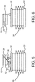
FIG. 5 is a side schematic view of a wiper blade and air operated mechanism according to the first embodiment of the disclosure. -
FIG. 6 is a front schematic view of a wiper blade and air operated mechanism according to the first embodiment of the disclosure. -
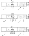
FIG. 7 is a side schematic view of a fluid ejection and vaporization device containing a cleaning apparatus according to a second embodiment of the disclosure, wherein a wiper blade of the cleaning apparatus is in a first position. -
FIG. 8 is a side schematic view of the fluid ejection and vaporization device according to the second embodiment of the disclosure, wherein the wiper blade of the cleaning apparatus is in a second position. -
FIG. 9 is a side schematic view of the fluid ejection and vaporization device according to the second embodiment of the disclosure, wherein the wiper blade of the cleaning apparatus has moved from the second position to the first position across an ejection head. -
FIG. 10 is a front schematic view of a wiper blade and air operated mechanism according to the second embodiment of the disclosure. -
FIG. 11 is a side schematic view of a wiper blade and air operated mechanism according to the second embodiment of the disclosure. -
FIG. 12 is a side schematic view of a fluid ejection and vaporization device containing a cleaning apparatus according to a third embodiment of the disclosure, wherein a wiper blade of the cleaning apparatus is in a first position. -
FIG. 13 is a side schematic view of the fluid ejection and vaporization device according to the third embodiment of the disclosure, wherein the wiper blade of the cleaning apparatus is in a second position. -
FIG. 14 is a side schematic view of the fluid ejection and vaporization device according to the third embodiment of the disclosure, wherein the wiper blade of the cleaning apparatus has moved from the second position to the first position across an ejection head. -
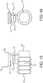
FIG. 15 is a side schematic view of a wiper blade and air operated mechanism according to the third embodiment of the disclosure. -
FIG. 16 is a front schematic view of a wiper blade and air operated mechanism according to the third embodiment of the disclosure. - The disclosure is directed to fluid ejection and vaporizing devices as schematically shown in
FIGS. 2-4 ,7-9 and12-14 and maintenance apparatuses as shown schematically inFIGS. 5-6 ,10-11 and15-16 . In all of the embodiment described herein, a fluid is ejected from an ejection head 10 (FIG. 1 ) onto avaporization heater 12 wherein the fluid is vaporized and flows through amouthpiece 22 out of the fluid ejection andvaporization device 20. The fluid ejected from theejection head 10 is provided by afluid reservoir 14 throughejection nozzles 16 in theejection head 10. Theejection head 10 may be a thermal microfluid ejection head or a bubble pump microfluid ejection head. Fluid ejection from theejection head 10 is controlled so as to provide a predetermined amount of vapor to a user of the fluid ejection and vaporization device. In some embodiments, the fluid ejection and vaporization device is an electronic cigarette. In other embodiments, the fluid ejection and vaporization device may be a device for vapor therapy or for delivery of vaporized pharmaceutical compositions to a user. Regardless of the particular fluid ejection and vaporization device, the principal of operation of the maintenance apparatus is generally the same. - For example, with reference to
FIGS. 2-6 , a fluid ejection andvaporization device 20 according to a first embodiment of the disclosure is illustrated.Such devices 20 may be used for a wide variety of applications wherein a liquid is ejected by theejection head 10 onto the vaporizingheater 12 to provide a vapor stream as described above with reference toFIG. 1 .Such devices 20 are typically hand held devices such as electronic cigarettes that have amouth piece 22 for inhaling vapors generated by thedevice 20. Themouthpiece 22 may include avapor exit conduit 24 for flow of vapors out of thedevice 10. As described above, it may be necessary to remove debris and contaminants from theejection head 10 so that thenozzles 16 of theejection head 10 do not become blocked or restricted whereby fluid ejection is inhibited or reduced. However, the small size of the fluid ejection andvaporization device 20 makes it difficult to use any kind of conventional ejection head cleaning mechanism. - Accordingly, with reference to
FIGS. 2-6 , there is shown an air operated mechanism such as abellows 26 or air bladder for moving a wiper blade 28 (FIG.6 ) across theejection head 10 from a first position illustrated inFIG. 2 to a second position illustrated inFIG. 3 when suction is applied to themouth piece 22. InFIGS. 2-4 , afirst end 30 of thebellows 26 is fixed or stationary within thedevice 20, and asecond end 32 of thebellows 26 is compressed toward thefirst end 30 of thebellows 26 in the direction ofarrow 34 when suction is applied to themouthpiece 22. A biasing device such as aspring 36 causes anarm 38 attached to the wiper blade 28 (FIG. 6 ) to move away from thesecond end 32 of thebellows 26 thus sweeping thewiper blade 28 across theejection head 10 from the first position shown inFIG. 2 to the second position shown inFIG. 3 . Thearm 38 may be attached to thesecond end 32 of thebellows 26 by a resilient connection such as rubber or thin plastic or ahinge 39. When suction is removed from themouthpiece 22, thebellows 26 returns to an uncompressed state shown inFIG. 4 thus again sweeping thewiper blade 28 across theejection head 10 from the second position (FIG. 3 ) to the first position (FIG. 4 ). The ends 30 and 32 of thebellows 26 may be biased away from each other by an internal or external spring. Air movement through the fluid ejection andvaporization device 20 that causes thebellows 26 to compress is illustrated by arrows 40 (FIG. 3 ). - When the bellows 26 is in the uncompressed state shown in
FIGS. 2 and 4 , thearm 38 is at anangle 41 of less than 90 degrees with respect to thesecond end 32 of thebellows 26, such as from about 20 to about 50 degrees, or from about 30 to about 45 degrees. When the bellows 26 is in the compressed state as shown inFIG. 3 , thearm 38 may be substantially perpendicular to thesecond end 32 of thebellows 26, such as an angle of from about 45 degrees to less than about 90 degrees with respect to thesecond end 32 of thebellows 26. - With reference to
FIGS. 7-11 , a second embodiment of the disclosure is illustrated. In the second embodiment, an air operated mechanism such as anair flapper 50 is used in the fluid ejection andvaporization device 20 instead of thebellows 26 described above. Theejection head 10,vaporization heater 12 andfluid reservoir 14 are described above and are disposed within the fluid ejection andvaporization device 20 as shown. - In this second embodiment, the
air flapper 50 has anarm 52 attached to awiper blade 54 for moving the wiper blade 54 (FIG.10 ) across theejection head 10 from a first position illustrated inFIG. 7 to a second position illustrated inFIG. 8 when suction is applied to themouth piece 22. Theflapper 50 andarm 52 are attached by means of ahinge 56 to asupport structure 58 within the fluid ejection andvaporization device 20. Thehinge 56 enables pivotal movement of theflapper 50 andarm 52 relative to thesupport structure 58. A biasing devices such asweak spring 60 is disposed between theflapper 50 andsupport structure 58 to bias theair flapper 50 to the first position shown inFIGS. 7, 9 and11 . Theair flapper 50 is disposed in an air flow path indicated byarrows 40 at an angle with respect to thesupport structure 58 so that it can move thewiper blade 54 across theejection head 10 when there is air flow through the fluid ejection andvaporization device 20. Accordingly, theair flapper 50 andarm 52 may be at anangle 61 ranging from about 25 to about 75 degrees relative to thesupport structure 58, such as from about 30 to about 50 degrees. - Moving from
FIGS. 7 to 9 , the operation of theair flapper 50 is illustrated schematically. InFIG. 7 , there is no suction on themouthpiece 22 and thus no air flow through the fluid ejection andvaporization device 20. Therefore thewiper blade 54 is in the first position shown inFIG.7 . When suction is applied to themouthpiece 22, air, indicated byarrows 40 is caused to flow through the fluid ejection andvaporization device 20 causing theair flapper 50 to move toward thesupport structure 58 thereby compressing thespring 60 and moving thewiper blade 54 across theejection head 10 as shown inFIG. 8 . When the suction on themouthpiece 22 is terminated, thespring 60 causes theair flapper 50 to move away from thesupport structure 58 causing thewiper blade 54 to move across theejection head 10 in the opposite direction back to the first position as shown inFIG. 9 . As thewiper blade 54 sweeps across theejection head 10 in both directions from the first position (FIGS. 7 and 9 ) to the second position (FIG. 8 ), debris and excess fluid are removed from the surface of theejection head 10. Thewiper blade 54 is made of a resilient material and will flex a sufficient amount to cause thewiper blade 54 to remain in contact with theejection head 10 regardless of the position of thewiper blade 54 in contact with theejection head 10 inFIGS. 7-9 . In the alternative, thearm 52 may flex as thewiper blade 54 moves across theejection head 10 in the sequence of positions shown inFIGS. 7-9 . - A third embodiment of the disclosure is illustrated in
FIGS. 12-16 . In this embodiment, the air operated mechanism is again a bellows 70 or bladder, however, compression of thebellows 70 causes lateral movement of anarm 72 attached to a wiper blade 74 (FIGS. 12-14 ) rather than angular movement of thearm 38 as shown inFIG. 5 in the first embodiment ofFIGS. 1-6 . Unlike the first and second embodiment, the third embodiment does not require the use of thebiasing devices bellows 70 may include an internal or external spring or biasing device in order to return thebellows 70 from a compressed position to an uncompressed position. - In
FIG. 13 , afirst end 76 of thebellows 70 is fixed or stationary within thedevice 20, and asecond end 78 of thebellows 70 is compressed toward thefirst end 76 of thebellows 70 in the direction ofarrow 80 when suction is applied to themouthpiece 22. Accordingly, thebellows 70 is shown in a first uncompressed state inFIG. 12 wherein thewiper blade 74 is adjacent afirst end 82 of theejection head 10. When suction is applied to themouthpiece 22, air movement through the fluid ejection andvaporization device 20 as indicated byarrows 86, causes thebellows 70 to compress as shown inFIG. 13 there by sweeping thewiper blade 74 across theejection head 10 from thefirst end 82 to asecond end 84 of theejection head 10. When suction is removed from themouthpiece 22, thebellows 70 returns to an uncompressed state shown inFIG. 14 thus again sweeping thewiper blade 74 across the ejection head from the second end 84 (FIG. 13 ) to the first end 82 (FIG. 14 ). - As with the first embodiment, the ends 76 and 78 of the
bellows 70 may be biased away from each other by an internal or external spring. Air movement through the fluid ejection andvaporization device 20 that causes thebellows 70 to compress is illustrated byFIG. 13 . - It will be appreciated that the air operated mechanism of the third embodiment is simpler and has fewer moving parts than the air operated mechanism of the other two embodiments.
- In all of the embodiments described herein, the fluid ejection and
vaporization device 20 may be made from a wide variety of materials including plastics, metals, glass, ceramic and the like provided the materials are compatible with the fluids to be ejected and vaporized by thedevice 20. A particularly suitable material may be selected from polyvinyl chloride, high density polyethylene, polycarbonate, stainless steel, surgical steel, and the like. All parts, including themouthpiece 22 that come in contact with fluids and vapors may be made of plastic. The wiper blade may be made of a resilient material such as an elastomeric material, natural rubber, fluoropolymer, and the like for wiping theejection head 10. As with the other components of the fluid ejection and vaporization device the wiper blade should be made of a material that is resistant to the fluids used in and vapors generated by the fluid ejection andvaporization device 20. - In the first and third embodiments, the bellows may be made from a resilient material such as cloth, fiberglass, plastic and the like. The air flapper of the second embodiment may be made of rigid material such as metal or plastic.
- While particular embodiments have been described, alternatives, modifications, variations, improvements, and substantial equivalents that are or can be presently unforeseen can arise to applicants or others skilled in the art. Accordingly, the appended claims as filed and as they can be amended are intended to embrace all such alternatives, modifications variations, improvements, and substantial equivalents.
Claims (15)
- An maintenance apparatus for a fluid ejection and vaporization device (20) comprising:a wiper blade (28, 54, 74), sweeping an ejection head (10) of the fluid ejection and vaporization device (20); andan air operated mechanism (26, 50, 70), attached to the wiper blade (28, 54, 74) and operated by a flow of air through the fluid ejection and vaporization (20) to move the wiper blade (28, 54, 74) across the ejection head (10).
- The maintenance apparatus of claim 1, wherein the air operated mechanism (26, 50, 70) has a first end (30, 76) fixed within the fluid ejection and vaporization device (20) and a second end (32, 78) moveable relative to the first end (30, 76),
the second end (32, 78) is attached to the wiper blade (28, 54, 74). - The maintenance apparatus of claim 1 or 2, wherein the wiper blade (28, 54, 74) is disposed between the ejection head (10) and a vaporizing heater (12) in the fluid ejection and vaporization device (20).
- The maintenance apparatus of claim 2, comprising an arm (38, 52, 72) connected to the second end (32, 78) of the air operated mechanism (26, 50, 70), the air operated mechanism (26, 50, 70) is attached to the wiper blade (28, 54, 74) through the arm (38, 52, 72).
- The maintenance apparatus of any one of claims 1-4, wherein the air operated mechanism (26, 50, 70) comprises an air bladder.
- The maintenance apparatus of any one of claims 1-4, wherein the air bladder comprises a spring bellows (26, 70).
- The maintenance apparatus of any one of claims 1-4, wherein the air operated mechanism (26, 50, 70) comprises an air operated flapper (50).
- The maintenance apparatus of claim7, wherein the air operated flapper (50) further comprises a spring (60) for biasing the air operated flapper (50) to a first position.
- The maintenance apparatus of any one of claims 1-8, wherein the air operated mechanism (26, 50, 70) is operated by inhaling vapors generated by the fluid ejection and vaporization device (20).
- The maintenance apparatus of any one of claims 1-9, wherein the air operated mechanism (26, 50, 70) is disposed between the vaporizing heater (12) and a mouthpiece (22) of the fluid ejection and vaporization device (20) on a side of the vaporizing heater (12) close to the mouthpiece (22).
- The maintenance apparatus of claim 10,
wherein the second end (32, 78) of the air operated mechanism (26, 50, 70) is moved by the flow of air to move the wiper blade (28, 54, 74) to sweep from a first position to a second position across the ejection head (10). - The maintenance apparatus of claim 11, wherein the air operated mechanism (26, 50, 70) comprises a biasing device (36, 60) and is biased by the biasing device (36, 60) in order to return the wiper blade (28, 54, 74) to the first position from the second position when the flow of air ceases.
- The maintenance apparatus of claim 11, wherein the air flows through the mouthpiece (22) of the fluid ejection and vaporization device (20).
- A fluid ejection and vaporization device comprising the maintenance apparatus of any one of claims 1-13.
- The fluid ejection and vaporization device of claim 14, wherein the fluid ejection and vaporization device comprises an electronic cigarette.
Applications Claiming Priority (1)
| Application Number | Priority Date | Filing Date | Title |
|---|---|---|---|
| US15/094,107 US10206426B2 (en) | 2016-04-08 | 2016-04-08 | Maintenance apparatus and method for vaporizing device |
Publications (2)
| Publication Number | Publication Date |
|---|---|
| EP3235534A1 true EP3235534A1 (en) | 2017-10-25 |
| EP3235534B1 EP3235534B1 (en) | 2021-07-21 |
Family
ID=58536767
Family Applications (1)
| Application Number | Title | Priority Date | Filing Date |
|---|---|---|---|
| EP17165177.1A Active EP3235534B1 (en) | 2016-04-08 | 2017-04-06 | Fluid ejection and vaporizing device and maintenance apparatus thereof |
Country Status (4)
| Country | Link |
|---|---|
| US (1) | US10206426B2 (en) |
| EP (1) | EP3235534B1 (en) |
| JP (1) | JP6897251B2 (en) |
| CN (1) | CN107259646B (en) |
Families Citing this family (23)
| Publication number | Priority date | Publication date | Assignee | Title |
|---|---|---|---|---|
| US20160345631A1 (en) | 2005-07-19 | 2016-12-01 | James Monsees | Portable devices for generating an inhalable vapor |
| US10279934B2 (en) | 2013-03-15 | 2019-05-07 | Juul Labs, Inc. | Fillable vaporizer cartridge and method of filling |
| USD842536S1 (en) | 2016-07-28 | 2019-03-05 | Juul Labs, Inc. | Vaporizer cartridge |
| US10058129B2 (en) | 2013-12-23 | 2018-08-28 | Juul Labs, Inc. | Vaporization device systems and methods |
| US10159282B2 (en) | 2013-12-23 | 2018-12-25 | Juul Labs, Inc. | Cartridge for use with a vaporizer device |
| USD825102S1 (en) | 2016-07-28 | 2018-08-07 | Juul Labs, Inc. | Vaporizer device with cartridge |
| US20160366947A1 (en) | 2013-12-23 | 2016-12-22 | James Monsees | Vaporizer apparatus |
| PT3508080T (en) | 2013-12-23 | 2021-03-02 | Juul Labs Int Inc | VAPORIZATION DEVICE SYSTEMS AND METHODS |
| US10076139B2 (en) | 2013-12-23 | 2018-09-18 | Juul Labs, Inc. | Vaporizer apparatus |
| CN112155255B (en) | 2014-12-05 | 2025-10-28 | 尤尔实验室有限公司 | Corrected dose control |
| EP3413960B1 (en) | 2016-02-11 | 2021-03-31 | Juul Labs, Inc. | Fillable vaporizer cartridge and method of filling |
| SG11201806801VA (en) | 2016-02-11 | 2018-09-27 | Juul Labs Inc | Securely attaching cartridges for vaporizer devices |
| US10405582B2 (en) | 2016-03-10 | 2019-09-10 | Pax Labs, Inc. | Vaporization device with lip sensing |
| USD849996S1 (en) | 2016-06-16 | 2019-05-28 | Pax Labs, Inc. | Vaporizer cartridge |
| USD851830S1 (en) | 2016-06-23 | 2019-06-18 | Pax Labs, Inc. | Combined vaporizer tamp and pick tool |
| USD836541S1 (en) | 2016-06-23 | 2018-12-25 | Pax Labs, Inc. | Charging device |
| EP3272236B1 (en) | 2016-07-22 | 2021-06-16 | Fontem Holdings 1 B.V. | Electronic smoking device |
| USD887632S1 (en) | 2017-09-14 | 2020-06-16 | Pax Labs, Inc. | Vaporizer cartridge |
| CN110340040A (en) * | 2018-04-04 | 2019-10-18 | 深圳御烟实业有限公司 | Tool for cleaning electric heating smoking set |
| US11413409B2 (en) | 2018-09-12 | 2022-08-16 | Juul Labs, Inc. | Vaporizer including positive temperature coefficient of resistivity (PTCR) heating element |
| EP4099856B1 (en) | 2020-02-04 | 2025-02-26 | Juul Labs, Inc. | Aerosol dispensing device with disposable container |
| WO2023006369A1 (en) | 2021-07-27 | 2023-02-02 | Jt International Sa | Inhalation device with at least one liquid jet device |
| CN113925208B (en) * | 2021-11-25 | 2024-01-16 | 深圳市汉清达科技有限公司 | A heating device for electronic cigarettes |
Citations (4)
| Publication number | Priority date | Publication date | Assignee | Title |
|---|---|---|---|---|
| US20030094187A1 (en) * | 2001-11-21 | 2003-05-22 | Berthold Maiwald | Cleaning device for a glue-spreading element |
| JP2004283245A (en) * | 2003-03-19 | 2004-10-14 | Canon Inc | Droplet ejection device |
| US20110175960A1 (en) * | 2009-03-09 | 2011-07-21 | Canon Kabushiki Kaisha | Liquid ejection apparatus and liquid ejection method |
| US8975764B1 (en) * | 2010-11-29 | 2015-03-10 | Benyamin Abehasera | Electronic cigarette with integrated charging mechanism |
Family Cites Families (30)
| Publication number | Priority date | Publication date | Assignee | Title |
|---|---|---|---|---|
| IL83826A (en) | 1987-09-08 | 1991-03-10 | Inventor S Funding Corp Ltd | Plastic mouthpiece for simulated smoking |
| US5249586A (en) | 1991-03-11 | 1993-10-05 | Philip Morris Incorporated | Electrical smoking |
| CN100566769C (en) * | 1993-06-29 | 2009-12-09 | 茵捷特数码浮质有限公司 | Utilize suction to take the method and the utensil of material |
| WO1995001137A1 (en) * | 1993-06-29 | 1995-01-12 | Voges Innovation Pty. Ltd. | Dispenser |
| US5555461A (en) * | 1994-01-03 | 1996-09-10 | Xerox Corporation | Self cleaning wiper blade for cleaning nozzle faces of ink jet printheads |
| US5548310A (en) * | 1994-10-17 | 1996-08-20 | Xerox Corporation | Automatic positioning of wiper blades in an ink jet printer maintenance station |
| KR200151933Y1 (en) * | 1996-04-08 | 1999-07-15 | 윤종용 | Service station of inkjet printer |
| US5954979A (en) | 1997-10-16 | 1999-09-21 | Philip Morris Incorporated | Heater fixture of an electrical smoking system |
| US6116247A (en) | 1998-10-21 | 2000-09-12 | Philip Morris Incorporated | Cleaning unit for the heater fixture of a smoking device |
| US6125866A (en) | 1998-11-10 | 2000-10-03 | Philip Morris Incorporated | Pump cleaning unit for the heater fixture of a smoking device |
| US6517187B1 (en) * | 2001-09-14 | 2003-02-11 | Xerox Corporation | Method and apparatus for cleaning residual ink from printhead nozzle faces |
| JP4389443B2 (en) * | 2002-12-20 | 2009-12-24 | セイコーエプソン株式会社 | Wiping unit for inkjet head, liquid droplet ejection apparatus including the same, and method for manufacturing electro-optical device |
| US7275534B2 (en) * | 2003-01-31 | 2007-10-02 | Hewlett-Packard Development Company, L.P. | Medicament ejector with ejection port servicing |
| JP2004350976A (en) * | 2003-05-29 | 2004-12-16 | Canon Inc | Droplet ejection device for lung suction |
| JP2004350971A (en) * | 2003-05-29 | 2004-12-16 | Canon Inc | Droplet ejection device |
| CN2719043Y (en) | 2004-04-14 | 2005-08-24 | 韩力 | Atomized electronic cigarette |
| JP4241639B2 (en) * | 2005-02-14 | 2009-03-18 | セイコーエプソン株式会社 | Droplet discharge device and maintenance method of droplet discharge head |
| JP4934678B2 (en) * | 2005-12-23 | 2012-05-16 | アストラゼネカ・アクチエボラーグ | New device |
| JP4328817B2 (en) * | 2007-09-10 | 2009-09-09 | キヤノン株式会社 | Drug delivery device |
| JP5621276B2 (en) * | 2010-03-01 | 2014-11-12 | セイコーエプソン株式会社 | Droplet discharge device |
| JP5569223B2 (en) * | 2010-07-30 | 2014-08-13 | ブラザー工業株式会社 | Liquid ejection device |
| US8672448B2 (en) * | 2011-11-11 | 2014-03-18 | Seiko Epson Corporation | Wiper unit and liquid ejecting apparatus |
| NO2797450T3 (en) | 2011-12-30 | 2018-04-21 | ||
| WO2013138384A2 (en) | 2012-03-12 | 2013-09-19 | Uptoke Llc | Electronic vaporizing device and methods for use |
| US9918496B2 (en) * | 2013-07-24 | 2018-03-20 | Altria Client Services Llc | Electronic smoking article |
| US20170064997A1 (en) * | 2014-02-28 | 2017-03-09 | Beyond Twenty Ltd. | Electronic vaporiser system |
| US9642397B2 (en) * | 2014-03-31 | 2017-05-09 | Westfield Limited (Ltd.) | Personal vaporizer with liquid supply by suction |
| US10016575B2 (en) * | 2014-06-03 | 2018-07-10 | Endoclear Llc | Cleaning devices, systems and methods |
| US11229757B2 (en) * | 2015-04-15 | 2022-01-25 | Philip Morris Products S.A. | Dry powder inhalers with partial dosage delivery |
| US9914307B2 (en) * | 2015-12-01 | 2018-03-13 | Seiko Epson Corporation | Liquid ejecting apparatus and maintenance method of liquid ejecting apparatus |
-
2016
- 2016-04-08 US US15/094,107 patent/US10206426B2/en active Active
-
2017
- 2017-04-06 EP EP17165177.1A patent/EP3235534B1/en active Active
- 2017-04-07 CN CN201710223512.8A patent/CN107259646B/en not_active Expired - Fee Related
- 2017-04-07 JP JP2017076883A patent/JP6897251B2/en not_active Expired - Fee Related
Patent Citations (4)
| Publication number | Priority date | Publication date | Assignee | Title |
|---|---|---|---|---|
| US20030094187A1 (en) * | 2001-11-21 | 2003-05-22 | Berthold Maiwald | Cleaning device for a glue-spreading element |
| JP2004283245A (en) * | 2003-03-19 | 2004-10-14 | Canon Inc | Droplet ejection device |
| US20110175960A1 (en) * | 2009-03-09 | 2011-07-21 | Canon Kabushiki Kaisha | Liquid ejection apparatus and liquid ejection method |
| US8975764B1 (en) * | 2010-11-29 | 2015-03-10 | Benyamin Abehasera | Electronic cigarette with integrated charging mechanism |
Also Published As
| Publication number | Publication date |
|---|---|
| CN107259646B (en) | 2020-09-29 |
| US10206426B2 (en) | 2019-02-19 |
| EP3235534B1 (en) | 2021-07-21 |
| US20170290369A1 (en) | 2017-10-12 |
| JP2017185488A (en) | 2017-10-12 |
| JP6897251B2 (en) | 2021-06-30 |
| CN107259646A (en) | 2017-10-20 |
Similar Documents
| Publication | Publication Date | Title |
|---|---|---|
| US10206426B2 (en) | Maintenance apparatus and method for vaporizing device | |
| EP1007142B1 (en) | A sprayer for fibrin glue | |
| CN1104310C (en) | Liquid container | |
| CN108472677B (en) | Liquid material discharge device | |
| JP6334504B2 (en) | Single nasal drug delivery device | |
| JP2021520266A5 (en) | ||
| US4528996A (en) | Orifice plate cleaning system | |
| JP2011519307A (en) | Disposable spray gun cartridge | |
| KR102635289B1 (en) | Cleaning apparatus and cleaning method of ink-jet head and printing apparatus | |
| EP1442764B1 (en) | Medicament ejector with ejection port servicing | |
| FI3752365T3 (en) | Print head and printing method | |
| EP3517220B1 (en) | Liquid material-discharging device | |
| CN108248014B (en) | Fluid ejection device | |
| KR20160029694A (en) | Apparatus and methods for dispensing small beads of viscous material | |
| TWI821257B (en) | Liquid material discharge device | |
| EP3246061A1 (en) | Vaporizing device and maintenance apparatus for vaporizing device | |
| CN116761648A (en) | sprayer | |
| JP5549175B2 (en) | Surgical equipment | |
| JP6086821B2 (en) | Trigger type ejector | |
| US11571704B2 (en) | Aseptic aerosol misting device | |
| JP3599726B2 (en) | Micro liquid suction and discharge device | |
| CN104068915A (en) | Fluid ejection device and medical apparatus | |
| JP6569083B2 (en) | INK JET HEAD CLEANING DEVICE, CLEANING METHOD, AND PRINTING DEVICE | |
| US20070040865A1 (en) | Maintenance apparatuses for fluid injectors and fluid injection devices integrated therewith | |
| JP5907203B2 (en) | Nozzle part for fluid ejecting mechanism, fluid ejecting apparatus, and surgical apparatus |
Legal Events
| Date | Code | Title | Description |
|---|---|---|---|
| PUAI | Public reference made under article 153(3) epc to a published international application that has entered the european phase |
Free format text: ORIGINAL CODE: 0009012 |
|
| STAA | Information on the status of an ep patent application or granted ep patent |
Free format text: STATUS: THE APPLICATION HAS BEEN PUBLISHED |
|
| AK | Designated contracting states |
Kind code of ref document: A1 Designated state(s): AL AT BE BG CH CY CZ DE DK EE ES FI FR GB GR HR HU IE IS IT LI LT LU LV MC MK MT NL NO PL PT RO RS SE SI SK SM TR |
|
| AX | Request for extension of the european patent |
Extension state: BA ME |
|
| STAA | Information on the status of an ep patent application or granted ep patent |
Free format text: STATUS: REQUEST FOR EXAMINATION WAS MADE |
|
| 17P | Request for examination filed |
Effective date: 20180404 |
|
| RBV | Designated contracting states (corrected) |
Designated state(s): AL AT BE BG CH CY CZ DE DK EE ES FI FR GB GR HR HU IE IS IT LI LT LU LV MC MK MT NL NO PL PT RO RS SE SI SK SM TR |
|
| STAA | Information on the status of an ep patent application or granted ep patent |
Free format text: STATUS: EXAMINATION IS IN PROGRESS |
|
| 17Q | First examination report despatched |
Effective date: 20200624 |
|
| REG | Reference to a national code |
Ref country code: DE Ref legal event code: R079 Ref document number: 602017042360 Country of ref document: DE Free format text: PREVIOUS MAIN CLASS: A61M0015060000 Ipc: A61M0011040000 |
|
| GRAP | Despatch of communication of intention to grant a patent |
Free format text: ORIGINAL CODE: EPIDOSNIGR1 |
|
| STAA | Information on the status of an ep patent application or granted ep patent |
Free format text: STATUS: GRANT OF PATENT IS INTENDED |
|
| RIC1 | Information provided on ipc code assigned before grant |
Ipc: A61M 11/04 20060101AFI20210317BHEP Ipc: A61M 15/00 20060101ALI20210317BHEP Ipc: A24F 40/85 20200101ALI20210317BHEP Ipc: A61M 15/02 20060101ALI20210317BHEP Ipc: A61M 15/06 20060101ALI20210317BHEP Ipc: A24F 40/48 20200101ALI20210317BHEP |
|
| INTG | Intention to grant announced |
Effective date: 20210408 |
|
| GRAS | Grant fee paid |
Free format text: ORIGINAL CODE: EPIDOSNIGR3 |
|
| GRAA | (expected) grant |
Free format text: ORIGINAL CODE: 0009210 |
|
| STAA | Information on the status of an ep patent application or granted ep patent |
Free format text: STATUS: THE PATENT HAS BEEN GRANTED |
|
| AK | Designated contracting states |
Kind code of ref document: B1 Designated state(s): AL AT BE BG CH CY CZ DE DK EE ES FI FR GB GR HR HU IE IS IT LI LT LU LV MC MK MT NL NO PL PT RO RS SE SI SK SM TR |
|
| REG | Reference to a national code |
Ref country code: GB Ref legal event code: FG4D |
|
| REG | Reference to a national code |
Ref country code: CH Ref legal event code: EP |
|
| REG | Reference to a national code |
Ref country code: DE Ref legal event code: R096 Ref document number: 602017042360 Country of ref document: DE |
|
| REG | Reference to a national code |
Ref country code: AT Ref legal event code: REF Ref document number: 1412015 Country of ref document: AT Kind code of ref document: T Effective date: 20210815 |
|
| REG | Reference to a national code |
Ref country code: IE Ref legal event code: FG4D |
|
| REG | Reference to a national code |
Ref country code: LT Ref legal event code: MG9D |
|
| REG | Reference to a national code |
Ref country code: NL Ref legal event code: MP Effective date: 20210721 |
|
| REG | Reference to a national code |
Ref country code: AT Ref legal event code: MK05 Ref document number: 1412015 Country of ref document: AT Kind code of ref document: T Effective date: 20210721 |
|
| PG25 | Lapsed in a contracting state [announced via postgrant information from national office to epo] |
Ref country code: SE Free format text: LAPSE BECAUSE OF FAILURE TO SUBMIT A TRANSLATION OF THE DESCRIPTION OR TO PAY THE FEE WITHIN THE PRESCRIBED TIME-LIMIT Effective date: 20210721 Ref country code: RS Free format text: LAPSE BECAUSE OF FAILURE TO SUBMIT A TRANSLATION OF THE DESCRIPTION OR TO PAY THE FEE WITHIN THE PRESCRIBED TIME-LIMIT Effective date: 20210721 Ref country code: LT Free format text: LAPSE BECAUSE OF FAILURE TO SUBMIT A TRANSLATION OF THE DESCRIPTION OR TO PAY THE FEE WITHIN THE PRESCRIBED TIME-LIMIT Effective date: 20210721 Ref country code: BG Free format text: LAPSE BECAUSE OF FAILURE TO SUBMIT A TRANSLATION OF THE DESCRIPTION OR TO PAY THE FEE WITHIN THE PRESCRIBED TIME-LIMIT Effective date: 20211021 Ref country code: AT Free format text: LAPSE BECAUSE OF FAILURE TO SUBMIT A TRANSLATION OF THE DESCRIPTION OR TO PAY THE FEE WITHIN THE PRESCRIBED TIME-LIMIT Effective date: 20210721 Ref country code: NO Free format text: LAPSE BECAUSE OF FAILURE TO SUBMIT A TRANSLATION OF THE DESCRIPTION OR TO PAY THE FEE WITHIN THE PRESCRIBED TIME-LIMIT Effective date: 20211021 Ref country code: NL Free format text: LAPSE BECAUSE OF FAILURE TO SUBMIT A TRANSLATION OF THE DESCRIPTION OR TO PAY THE FEE WITHIN THE PRESCRIBED TIME-LIMIT Effective date: 20210721 Ref country code: PT Free format text: LAPSE BECAUSE OF FAILURE TO SUBMIT A TRANSLATION OF THE DESCRIPTION OR TO PAY THE FEE WITHIN THE PRESCRIBED TIME-LIMIT Effective date: 20211122 Ref country code: FI Free format text: LAPSE BECAUSE OF FAILURE TO SUBMIT A TRANSLATION OF THE DESCRIPTION OR TO PAY THE FEE WITHIN THE PRESCRIBED TIME-LIMIT Effective date: 20210721 Ref country code: ES Free format text: LAPSE BECAUSE OF FAILURE TO SUBMIT A TRANSLATION OF THE DESCRIPTION OR TO PAY THE FEE WITHIN THE PRESCRIBED TIME-LIMIT Effective date: 20210721 Ref country code: HR Free format text: LAPSE BECAUSE OF FAILURE TO SUBMIT A TRANSLATION OF THE DESCRIPTION OR TO PAY THE FEE WITHIN THE PRESCRIBED TIME-LIMIT Effective date: 20210721 |
|
| PG25 | Lapsed in a contracting state [announced via postgrant information from national office to epo] |
Ref country code: PL Free format text: LAPSE BECAUSE OF FAILURE TO SUBMIT A TRANSLATION OF THE DESCRIPTION OR TO PAY THE FEE WITHIN THE PRESCRIBED TIME-LIMIT Effective date: 20210721 Ref country code: LV Free format text: LAPSE BECAUSE OF FAILURE TO SUBMIT A TRANSLATION OF THE DESCRIPTION OR TO PAY THE FEE WITHIN THE PRESCRIBED TIME-LIMIT Effective date: 20210721 Ref country code: GR Free format text: LAPSE BECAUSE OF FAILURE TO SUBMIT A TRANSLATION OF THE DESCRIPTION OR TO PAY THE FEE WITHIN THE PRESCRIBED TIME-LIMIT Effective date: 20211022 |
|
| REG | Reference to a national code |
Ref country code: DE Ref legal event code: R097 Ref document number: 602017042360 Country of ref document: DE |
|
| PG25 | Lapsed in a contracting state [announced via postgrant information from national office to epo] |
Ref country code: DK Free format text: LAPSE BECAUSE OF FAILURE TO SUBMIT A TRANSLATION OF THE DESCRIPTION OR TO PAY THE FEE WITHIN THE PRESCRIBED TIME-LIMIT Effective date: 20210721 |
|
| PLBE | No opposition filed within time limit |
Free format text: ORIGINAL CODE: 0009261 |
|
| STAA | Information on the status of an ep patent application or granted ep patent |
Free format text: STATUS: NO OPPOSITION FILED WITHIN TIME LIMIT |
|
| PG25 | Lapsed in a contracting state [announced via postgrant information from national office to epo] |
Ref country code: SM Free format text: LAPSE BECAUSE OF FAILURE TO SUBMIT A TRANSLATION OF THE DESCRIPTION OR TO PAY THE FEE WITHIN THE PRESCRIBED TIME-LIMIT Effective date: 20210721 Ref country code: SK Free format text: LAPSE BECAUSE OF FAILURE TO SUBMIT A TRANSLATION OF THE DESCRIPTION OR TO PAY THE FEE WITHIN THE PRESCRIBED TIME-LIMIT Effective date: 20210721 Ref country code: RO Free format text: LAPSE BECAUSE OF FAILURE TO SUBMIT A TRANSLATION OF THE DESCRIPTION OR TO PAY THE FEE WITHIN THE PRESCRIBED TIME-LIMIT Effective date: 20210721 Ref country code: EE Free format text: LAPSE BECAUSE OF FAILURE TO SUBMIT A TRANSLATION OF THE DESCRIPTION OR TO PAY THE FEE WITHIN THE PRESCRIBED TIME-LIMIT Effective date: 20210721 Ref country code: CZ Free format text: LAPSE BECAUSE OF FAILURE TO SUBMIT A TRANSLATION OF THE DESCRIPTION OR TO PAY THE FEE WITHIN THE PRESCRIBED TIME-LIMIT Effective date: 20210721 Ref country code: AL Free format text: LAPSE BECAUSE OF FAILURE TO SUBMIT A TRANSLATION OF THE DESCRIPTION OR TO PAY THE FEE WITHIN THE PRESCRIBED TIME-LIMIT Effective date: 20210721 |
|
| 26N | No opposition filed |
Effective date: 20220422 |
|
| PG25 | Lapsed in a contracting state [announced via postgrant information from national office to epo] |
Ref country code: IT Free format text: LAPSE BECAUSE OF FAILURE TO SUBMIT A TRANSLATION OF THE DESCRIPTION OR TO PAY THE FEE WITHIN THE PRESCRIBED TIME-LIMIT Effective date: 20210721 |
|
| REG | Reference to a national code |
Ref country code: CH Ref legal event code: PL |
|
| GBPC | Gb: european patent ceased through non-payment of renewal fee |
Effective date: 20220406 |
|
| REG | Reference to a national code |
Ref country code: BE Ref legal event code: MM Effective date: 20220430 |
|
| PG25 | Lapsed in a contracting state [announced via postgrant information from national office to epo] |
Ref country code: MC Free format text: LAPSE BECAUSE OF FAILURE TO SUBMIT A TRANSLATION OF THE DESCRIPTION OR TO PAY THE FEE WITHIN THE PRESCRIBED TIME-LIMIT Effective date: 20210721 Ref country code: LI Free format text: LAPSE BECAUSE OF NON-PAYMENT OF DUE FEES Effective date: 20220430 Ref country code: GB Free format text: LAPSE BECAUSE OF NON-PAYMENT OF DUE FEES Effective date: 20220406 Ref country code: FR Free format text: LAPSE BECAUSE OF NON-PAYMENT OF DUE FEES Effective date: 20220430 Ref country code: CH Free format text: LAPSE BECAUSE OF NON-PAYMENT OF DUE FEES Effective date: 20220430 Ref country code: LU Free format text: LAPSE BECAUSE OF NON-PAYMENT OF DUE FEES Effective date: 20220406 |
|
| PG25 | Lapsed in a contracting state [announced via postgrant information from national office to epo] |
Ref country code: BE Free format text: LAPSE BECAUSE OF NON-PAYMENT OF DUE FEES Effective date: 20220430 |
|
| PG25 | Lapsed in a contracting state [announced via postgrant information from national office to epo] |
Ref country code: IE Free format text: LAPSE BECAUSE OF NON-PAYMENT OF DUE FEES Effective date: 20220406 |
|
| PG25 | Lapsed in a contracting state [announced via postgrant information from national office to epo] |
Ref country code: HU Free format text: LAPSE BECAUSE OF FAILURE TO SUBMIT A TRANSLATION OF THE DESCRIPTION OR TO PAY THE FEE WITHIN THE PRESCRIBED TIME-LIMIT; INVALID AB INITIO Effective date: 20170406 |
|
| PG25 | Lapsed in a contracting state [announced via postgrant information from national office to epo] |
Ref country code: MK Free format text: LAPSE BECAUSE OF FAILURE TO SUBMIT A TRANSLATION OF THE DESCRIPTION OR TO PAY THE FEE WITHIN THE PRESCRIBED TIME-LIMIT Effective date: 20210721 Ref country code: CY Free format text: LAPSE BECAUSE OF FAILURE TO SUBMIT A TRANSLATION OF THE DESCRIPTION OR TO PAY THE FEE WITHIN THE PRESCRIBED TIME-LIMIT Effective date: 20210721 |
|
| PGFP | Annual fee paid to national office [announced via postgrant information from national office to epo] |
Ref country code: DE Payment date: 20240227 Year of fee payment: 8 |
|
| PG25 | Lapsed in a contracting state [announced via postgrant information from national office to epo] |
Ref country code: MT Free format text: LAPSE BECAUSE OF FAILURE TO SUBMIT A TRANSLATION OF THE DESCRIPTION OR TO PAY THE FEE WITHIN THE PRESCRIBED TIME-LIMIT Effective date: 20210721 |
|
| REG | Reference to a national code |
Ref country code: DE Ref legal event code: R119 Ref document number: 602017042360 Country of ref document: DE |
|
| PG25 | Lapsed in a contracting state [announced via postgrant information from national office to epo] |
Ref country code: TR Free format text: LAPSE BECAUSE OF FAILURE TO SUBMIT A TRANSLATION OF THE DESCRIPTION OR TO PAY THE FEE WITHIN THE PRESCRIBED TIME-LIMIT Effective date: 20210721 |
|
| PG25 | Lapsed in a contracting state [announced via postgrant information from national office to epo] |
Ref country code: DE Free format text: LAPSE BECAUSE OF NON-PAYMENT OF DUE FEES Effective date: 20251104 |