EP3235292B1 - Handover using dual active connections - Google Patents
Handover using dual active connections Download PDFInfo
- Publication number
- EP3235292B1 EP3235292B1 EP15869095.8A EP15869095A EP3235292B1 EP 3235292 B1 EP3235292 B1 EP 3235292B1 EP 15869095 A EP15869095 A EP 15869095A EP 3235292 B1 EP3235292 B1 EP 3235292B1
- Authority
- EP
- European Patent Office
- Prior art keywords
- handover
- access node
- connection
- user equipment
- network
- Prior art date
- Legal status (The legal status is an assumption and is not a legal conclusion. Google has not performed a legal analysis and makes no representation as to the accuracy of the status listed.)
- Active
Links
- 230000009977 dual effect Effects 0.000 title claims description 44
- 238000000034 method Methods 0.000 claims description 53
- 238000004891 communication Methods 0.000 claims description 43
- 238000012545 processing Methods 0.000 claims description 34
- 238000010586 diagram Methods 0.000 description 26
- 230000004044 response Effects 0.000 description 20
- 230000006870 function Effects 0.000 description 18
- 230000008569 process Effects 0.000 description 12
- 239000003550 marker Substances 0.000 description 6
- 238000005259 measurement Methods 0.000 description 6
- 230000001413 cellular effect Effects 0.000 description 5
- 238000012546 transfer Methods 0.000 description 4
- 230000001960 triggered effect Effects 0.000 description 4
- 238000013475 authorization Methods 0.000 description 3
- 230000005540 biological transmission Effects 0.000 description 2
- 238000005516 engineering process Methods 0.000 description 2
- 230000000977 initiatory effect Effects 0.000 description 2
- 230000003287 optical effect Effects 0.000 description 2
- 230000000737 periodic effect Effects 0.000 description 2
- 230000008901 benefit Effects 0.000 description 1
- 238000005266 casting Methods 0.000 description 1
- 230000009849 deactivation Effects 0.000 description 1
- 238000013461 design Methods 0.000 description 1
- 230000000694 effects Effects 0.000 description 1
- 230000006872 improvement Effects 0.000 description 1
- 230000007774 longterm Effects 0.000 description 1
- 238000010295 mobile communication Methods 0.000 description 1
- 238000012986 modification Methods 0.000 description 1
- 230000004048 modification Effects 0.000 description 1
- 239000013316 polymer of intrinsic microporosity Substances 0.000 description 1
- 230000011664 signaling Effects 0.000 description 1
Images


Classifications
-
- H—ELECTRICITY
- H04—ELECTRIC COMMUNICATION TECHNIQUE
- H04W—WIRELESS COMMUNICATION NETWORKS
- H04W36/00—Hand-off or reselection arrangements
- H04W36/16—Performing reselection for specific purposes
- H04W36/18—Performing reselection for specific purposes for allowing seamless reselection, e.g. soft reselection
-
- H—ELECTRICITY
- H04—ELECTRIC COMMUNICATION TECHNIQUE
- H04W—WIRELESS COMMUNICATION NETWORKS
- H04W36/00—Hand-off or reselection arrangements
- H04W36/0005—Control or signalling for completing the hand-off
- H04W36/0055—Transmission or use of information for re-establishing the radio link
- H04W36/0069—Transmission or use of information for re-establishing the radio link in case of dual connectivity, e.g. decoupled uplink/downlink
- H04W36/00698—Transmission or use of information for re-establishing the radio link in case of dual connectivity, e.g. decoupled uplink/downlink using different RATs
-
- H—ELECTRICITY
- H04—ELECTRIC COMMUNICATION TECHNIQUE
- H04W—WIRELESS COMMUNICATION NETWORKS
- H04W36/00—Hand-off or reselection arrangements
- H04W36/14—Reselecting a network or an air interface
-
- H—ELECTRICITY
- H04—ELECTRIC COMMUNICATION TECHNIQUE
- H04W—WIRELESS COMMUNICATION NETWORKS
- H04W36/00—Hand-off or reselection arrangements
- H04W36/14—Reselecting a network or an air interface
- H04W36/144—Reselecting a network or an air interface over a different radio air interface technology
-
- H—ELECTRICITY
- H04—ELECTRIC COMMUNICATION TECHNIQUE
- H04W—WIRELESS COMMUNICATION NETWORKS
- H04W76/00—Connection management
- H04W76/10—Connection setup
- H04W76/15—Setup of multiple wireless link connections
-
- H—ELECTRICITY
- H04—ELECTRIC COMMUNICATION TECHNIQUE
- H04W—WIRELESS COMMUNICATION NETWORKS
- H04W76/00—Connection management
- H04W76/30—Connection release
- H04W76/38—Connection release triggered by timers
-
- H—ELECTRICITY
- H04—ELECTRIC COMMUNICATION TECHNIQUE
- H04W—WIRELESS COMMUNICATION NETWORKS
- H04W88/00—Devices specially adapted for wireless communication networks, e.g. terminals, base stations or access point devices
- H04W88/02—Terminal devices
- H04W88/06—Terminal devices adapted for operation in multiple networks or having at least two operational modes, e.g. multi-mode terminals
Definitions
- Various features disclosed herein relate generally to cellular/wireless communication systems, and at least some features pertain more particularly to methods and devices for facilitating handovers of wireless services (e.g., cellular services) for mobile devices from one access point to another access point. Improvement of handoff procedures can enable and provide efficient use of power resources and aims to improve user experience.
- wireless services e.g., cellular services
- Mobile devices such as mobile phones, wireless modems, tablets, or any other device with a processor that communicates with other devices through wireless signals are becoming increasingly popular and are used more frequently. Subscribers using such mobile devices in a cellular/wireless communication network are typically authenticated by the wireless communication network before being granted access to initiate and/or receive calls and transmit and/or receive data.
- Handovers typically involve disconnecting from a first access point prior to connecting to a second access point.
- mobile devices cannot send data either over the first wireless connection (because the first wireless connection is terminated) nor over the second wireless connection (because the second wireless connection has not yet been established).
- Various features facilitate a handover of a communication connection while minimizing service interruptions by using dual active connections at a user equipment device.
- a first aspect provides a method operational on a user equipment device for facilitating a dual active handover.
- a first connection may be established with a first access node for communication services via a first network.
- An indication may be obtained that a handover to a second access node is to occur.
- Obtaining an indication that the handover is to occur may include at least one of: (a) receiving a message or indicator from the first access node that the handover is to occur, and/or (b) obtaining an indication that the handover is to occur includes making an autonomous decision by the user equipment device to initiate the handover.
- a second connection may then be established with a second access node for communication services, via the first network or a second network, while the first connection remains established.
- the first connection and second connection may be wireless connections over a single radio access network or over different radio access networks.
- the first connection and second connection may be concurrently active during the handover.
- the first connection and second connection may be established by sharing a single receiver at the user equipment device.
- the first connection may be established via a first receiver at the user equipment device and the second connection is established via a second receiver at the user equipment device.
- IP internet protocol
- IP internet protocol
- the first connection is terminated once the handover is completed.
- packets may be received over both the first connection and second connection.
- the user equipment may reorder the packets received and deletes duplicate packets received during handover. Also during handover and prior to terminating the first connection, the user equipment may transmitting packets over the second connection.
- the user equipment device may receive handover completed indication from the first access node or second access node.
- the handover completed indication may include at least one of: (a) an end marker indicating no more data to be transmitted; and/or (b) a radio resource control release from the first access node.
- a second aspect provides a user equipment device, comprising: a wireless communication circuit coupled to a processing circuit.
- the wireless communication circuit may be configured to communicate with a first network.
- the processing circuit may be configured to: (a) establish a first connection with a first access node for communication services via a first network; (b) obtain an indication that a handover to a second access node is to occur; (c) establish a second connection with a second access node for communication services, via the first network or a second network, while the first connection remains established; and/or (d) terminate the first connection once the handover is completed.
- a third aspect provides a method operational at a first access node for handing over communication services.
- a first connection may be established between the first access node and a user equipment device for communication services via a first network.
- a determination is then made to handover the communication services for the user equipment device to a second access node on a second network.
- the handover determination may be based, at least partially, on information obtained from the user equipment device related to a quality of the first connection.
- the handover determination may include receiving an indication that the handover is to occur from the user equipment device.
- a handover request may be sent to initiate the handover.
- the first access node continues to receive packets intended for the user equipment device even after the handover has started. Those packets may be bicasted from the first access node to both the user equipment device and the second access node during the handover.
- the first connection may be terminated once the handover is completed.
- first network and the second network may share a common serving gateway (SGW) and Packet Data Network (PDN) gateway (PGW).
- first network and the second network may each have a different serving gateway (SGW) and Packet Data Network (PDN) gateway (PGW).
- exemplary is used herein to mean “serving as an example, instance, or illustration.” Any implementation or embodiment described herein as “exemplary” is not necessarily to be construed as preferred or advantageous over other embodiments or implementations. Likewise, the term “embodiments” does not require that all embodiments include the discussed feature, advantage or mode of operation.
- UE user equipment
- a "user equipment” or “UE” may include a mobile phone, a cellular phone, a smart phone, a session initiation protocol (SIP) phone, a pager, a wireless modem, a personal digital assistant, a personal information manager (PIMs), personal media players, client devices, subscriber devices, tablet computers, laptop computers, a satellite radio, a global positioning system, a multimedia device, a video device, a digital audio player (e.g., MP3 player), a camera, a game console, a tablet, , an entertainment device, a medical device, industrial equipment, actuator/sensor component, automotive component, metering equipment, IoE/IoT devices, and/or other mobile communication/computing devices which communicate, at least partially, through a wireless or cellular network.
- SIP session initiation protocol
- PIMs personal information manager
- access node is also meant to be interpreted broadly, and includes, for example, an evolved Node B (ENB), a base station, a base transceiver station, a radio base station, a radio transceiver, a basic service set (BSS), an extended service set (ESS), a network access point, and/or a network connectivity node that may be part of a radio access network and provides wireless network connectivity to one or more UEs.
- ENB evolved Node B
- BSS basic service set
- ESS extended service set
- network access point and/or a network connectivity node that may be part of a radio access network and provides wireless network connectivity to one or more UEs.
- a technique is disclosed to minimize service interruption of a wireless user equipment device during a handover from one access node to another access node by maintaining dual active connections during the handover.
- an initial/first connection with a first access node is maintained while establishing a second connection with a second access node.
- the user equipment device can receive data over the first connection and second connection during the handover.
- the first connection may be terminated (by the user equipment device or by timing out due to inactivity) after the handover is completed.
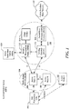
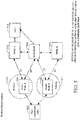
- FIG. 1 is a diagram illustrating an exemplary next generation communication network architecture, such as an evolved packet system (EPS) 100, according to some aspects/embodiments.
- the EPS 100 may include one or more user equipment (UE) 102, a Radio Access Network (RAN) 104 (e.g., Evolved Universal Mobile Telecommunication System (UMTS) Terrestrial Radio Access Network (E-UTRAN)), an Evolved Packet Core (EPC) 110, a Home Subscriber Server (HSS) 120, and a Packet Switched Network 122.
- UMTS Evolved Universal Mobile Telecommunication System
- E-UTRAN Evolved Universal Mobile Telecommunication System
- EPC Evolved Packet Core
- HSS Home Subscriber Server
- Packet Switched Network 122 Packet Switched Network
- the RAN 104 may include one or more access nodes A 106 and B 108. Additionally, other access nodes C 109, coupled to other RANs and/or other MMEs may also serve to provide connectivity to the UE 102. As the UE 102 moves, its wireless connection service with the first node A 106 may be handed over to another access node B 108 and/or C 109 (e.g., within the same RAN or different RANs).
- the first access node A 106 may be connected (or communicatively coupled) to the second access node B 108 via a backhaul interface X2.
- the first access node A 106 may serve as an access point to the EPC 110 for the UE 102.
- the first access node 106 may be connected by an interface S1 to the EPC 110.
- the EPC 110 may include a Mobility Management Entity (MME) 112, other MMEs 114, a Serving Gateway (SGW) 116, and a Packet Data Network (PDN) Gateway 118.
- MME 112 may be the control node that processes signaling between the UE 102 and the EPC 110. Generally, the MME 112 provides bearer and connection management. All user IP packets may be transferred through the Serving Gateway (SGW) 116, which itself is connected to the PDN Gateway 118.
- the PDN Gateway 118 may provide the UE internet protocol (IP) address allocation as well as other functions.
- IP internet protocol
- the PDN Gateway 118 may be connected to the packet switched data network 122.
- the packet switched data network 122 may include the Internet, an intranet, an IP Multimedia Subsystem (IMS), and a PS Streaming Service (PSS).
- IMS IP Multimedia Subsystem
- PSS PS
- the access nodes A 106 and B 108 typically communicate with each other via an "X2" interface.
- the access nodes A 106 and B 108 communicate with the EPC 110 (including the MME 112 and SGW 116) via an "S1" interface.
- Non-Access Stratum (NAS) protocols form the highest stratum of the control plane between the user equipment (UE) 102 and the MME 112.
- NAS protocols support mobility of the UE 102 and the session management procedures to establish and maintain IP connectivity between the UE 102 and a PDN gateway 118.
- the EPS 100 may utilize an EPS Session Management (ESM) protocol which provides procedures for the handling of EPS bearer contexts. Together with the bearer control provided by the Access Stratum, it provides the control of user plane bearers. The transmission of ESM messages is suspended during EMM procedures except for the attach procedure.
- ESM EPS Session Management
- the EPS 100 may utilize an EPS Mobility Management (EMM) protocol which provides procedures for the control of mobility when the User Equipment (UE) uses the Evolved UMTS Terrestrial Radio Access Network (E-UTRAN). It also provides control of security for the NAS protocols.
- EMM EPS Mobility Management
- a UE In existing EPS systems, a UE is supported by a single MME at any one time.
- MME relocation of the UE is required.
- the UE may be left without a data connection. For instance, as the UE switches from a first wireless connection with a first access node (coupled to a first MME) to a second wireless connection with a second access node (coupled to a second MME), there is a period of time in which the first wireless connection is terminated but the second wireless connection is not yet established.
- next generation networks and according to some aspects/embodiments, as the MME functionality is moved closer to the access nodes, the MME relocation procedures may occur much more frequently. Consequently, loss of connectivity for UE devices may become more noticeable.
- a new procedure is disclosed to optimize handover performance by using dual active connections with different access nodes (e.g., served by different MMEs) to allow the UE to maintain a data connection during a handover.
- an MME context per link/connection is setup with an access node for each UE being served. Such MME context is setup between the MME and access node.
- An MME context may include both an EPS Mobility Management (EMM) context and one or more EPS Session Management (ESM) contexts associated with the UE.
- EMM EPS Mobility Management
- ESM EPS Session Management
- An MME context applies to one or more radio access technologies (RATs), e.g., a multi-access MME context including wireless local area network (WLAN) and LTE.
- the EMM context for a UE is authenticated for access at the network provisioning the credentials used by the UE for attachment (home or visited AAA for roaming), i.e., the access credentials.
- the access credential function serves to enable service to the UE to be established securely and there may not necessarily be a billing relationship between the access credential provider and the serving network.
- One or more ESM contexts where each ESM context is associated with one or more APNs, may be used to host the ESM (session management) functions for each service.
- Some implementations may use more than one MME context simultaneously on a single connection to an access node.
- the access node may merge or reconcile the two MME contexts for a UE at the RAN and figure out mobility, conflicts, etc., between the two MME contexts.
- a single UE context is typically defined at the access node for the UE.
- One MME context implies only one identifier, e.g., global unique temporary identifier (GUTI), for the UE context at an access node.
- GUI global unique temporary identifier
- a UE may have multiple MME contexts active simultaneously when it has multiple links/connections active simultaneously. For example, the UE may be connected over two links to separate access nodes that are not served by the same MME.
- FIG. 1 illustrates an exemplary network in which one or more aspects and features may be implemented, these features may also be implemented on various types of networks, including subscriber networks, public data network (PDN) networks, wireless networks, etc.
- PDN public data network
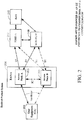
- FIG. 2 is a block diagram illustrating a first example of a handover using dual active connections within a single radio access network (RAN-A) 204 with a common mobility management entity (MME) 212 and using a common serving gateway (SGW) and PDN gateway (PGW) 208 according to some aspects/embodiments.
- RAN-A radio access network
- MME mobility management entity
- SGW serving gateway
- PGW PDN gateway
- a single authentication, authorization, and accounting (AAA) server 216 is used by the UE device 202 (i.e., one subscription is used by the UE device 202).
- the UE device 202 may include a transceiver circuit capable of receiving from two different connections, such as two separate receiver circuits or a single receiver circuit that can be shared (e.g., using multiplexing or timeslots) to receive from (and transmit to) two distinct connections.
- a handover of the UE device 202 occurs from a first connection via a first access node A 203 and to a second connection via a second access node B 205 while utilizing an X2 interface between the first access node A 203 and second access node B 205.
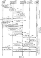
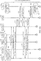
- FIG. 3 is a flow diagram illustrating one example of how a handover using the X2 interface between access nodes may be implemented using dual active connections for a UE device within the network environment of FIG. 2 according to some aspects/embodiments.
- the UE device 202 may have previously established a first connection or link (e.g., a radio bearer) with the serving first access node A 203.
- the UE device 202 may be configured for a dual active connection handover.
- the UE device 202 may provide a measurement report 304 (e.g., signal strength measurement, error packet count, etc.) to a currently serving access node A 203.
- the serving access node A 203 may make a decision 306 (e.g., based on the measurement report 304) on whether a handover is appropriate.
- a handover request 308 is sent to the second access node B 205 which decides on accepting the request (e.g., as part of admission control 310). If the second access node B 205 determines to accept the handover request 308, it may send a handover command 312 to the first access node A 203. Upon receipt of the handover command 312, the first access node A 203 may send a connection reconfiguration request 314 to the UE device 202.
- the UE device 202 may send a connection reconfiguration complete message 316 to the first access node A 203, indicating that the UE device 202 shall start the handover to the second access node B 205.
- the first access node A 203 may then send a handover complete message 318 to the second access node B 205.
- the UE device 202 may establish a second connection (with the second access node B 205) by sending a random access preamble 322 to the second access node B 205 and, in reply, receiving a random access response 328.
- the UE device 202 may have two concurrent connections, i.e., the first connection with the first access node A 203 and the second connection with the second access node B 205.
- the first access node A 203 may buffer packets to the UE device 202 and delivers in-transit packets 330 to the second access node B 205. For instance, the first access node A 203 may send an status transfer message 332 (e.g., to indicate packets for the UE device 202 are being forwarded) to the second access node B 205 and then a data forwarding message 334 including the in-transit packets intended for the UE device 202. That is, the packets arriving at the first access node A 203 for the UE device 202 during the handover procedure may be forwarded to the second access node B 205 which can then deliver them to the UE device 202.
- an status transfer message 332 e.g., to indicate packets for the UE device 202 are being forwarded
- a data forwarding message 334 including the in-transit packets intended for the UE device 202. That is, the packets arriving at the first access node A 203 for the UE device 202 during the handover procedure
- the second access node B 205 may send downlink data packets 336 to the UE device 202 while the UE device 202 may send uplink data packets 336 to the second access node B 205, which then forwards 338 them to the PGW/SGW 208.
- the forwarding of in-transit packets may be in addition to the first access node A 203 sending the packets directly to the UE device 202.
- the UE device 202 may simply discard any duplicate packets received (e.g., packet identifiers may be used to compare packets received from the first access node A 203 and the second access node B 205 and discard duplicate packets).
- the second access node B 205 may initiate a user plane switch (e.g., downlink path for the UE device 202) by sending a switch request 340 to the MME 212. This notifies the MME 212 that packets to the UE device 202 should be forwarded to the second access node B 205 instead of the first access node A 203.
- a user plane switch e.g., downlink path for the UE device 202
- the MME 212 may send a modify bearer request 342 to the PGW/SGW 208.
- This causes the PGW/SGW 208 to switch the downlink path 344 for the UE device 202 and send an end marker 346 to the first access node A 203.
- the first access node A 203 may forward this end marker 348 to the second access node B 205 to indicate that the second access node B 205 should takeover downlink communications for the UE device 202. Consequently, the second access node B 205 may transmit both uplink and downlink packet data 350 for the UE device 202.
- the PGW/SGW 208 may also send a modify bearer response 352 to indicate that the bearer for the UE device 202 has been successfully updated.
- the first access node A 203 may send a connection release message 356 to the UE device 202 to terminate the first connection. Additionally, the first access node A 203 may send a UE context release request 358 to the MME 212 and receives a UE context release complete 360 in response. Then, the second access node B 205 becomes the only serving node and the dual active handover is completed.
- the interruption can be avoided by having the first access node A 203 bi-casting cached downlink packet data to the UE device 202 and the second access node B 205.
- the second access node B 205 forwards the received packet data to the UE device 202.
- the UE device 202 due to its dual active capabilities, is able detect and dispose of duplicate packets that may be received.
- the handover can be performed via an S1 interface.
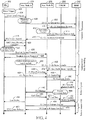
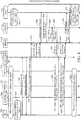
- FIG. 4 is a flow diagram illustrating one example of how a handover using an S1 interface between access nodes and an MME and SGW/PGW may be implemented using dual active connections for a UE device within the network environment of FIG. 2 according to some aspects/embodiments.
- the UE device 202 may have previously established a first connection with the serving first access node A 203.
- the UE device 202 may be configured for a dual active connection handover.
- the UE device 202 may provide a measurement report 404 (e.g., signal strength measurement, error packet count, etc.) to a currently serving access node A 203.
- the serving access node A 203 may make a decision 406 (e.g., based on the measurement report 404) on whether a handover is appropriate. If the access node A 203 decides to initiate a handover of connectivity service for the UE device 202 to a different second access node B 205, a handover required message 408 is sent to the MME 212.
- the MME 212 may then send a handover request message 410 to the second access node B 205.
- the second access node B 205 may perform admission control 412 which may result in a handover request acknowledge 414 being sent to the MME 212. If so, the MME 212 may send a handover command 416 to the first access node A 203.
- the first access node A 203 may send a connection reconfiguration request 418 to the UE device 202.
- the UE device 202 may send a connection reconfiguration complete message 420 to the first access node A 203, indicating that the UE device 202 shall start the handover to the second access node B 205.
- the UE device 202 may establish a second connection (with the second access node B 205) by sending a random access preamble 426 to the second access node B 205 and, in reply, receiving a random access response 428.
- the UE device 202 may have two concurrent connections, i.e., the first connection with the first access node A 203 and the second connection with the second access node B 205.
- the first access node A 203 may buffer packets to the UE device 202 and delivers in-transit packets 430 to the second access node B 205. For instance, the first access node A 203 may send an access node status transfer message 432 (e.g., to indicate packets for the UE device 202 are being forwarded) to the MME 212. In turn, the MME 212 may send an access node status transfer message 434 to the second access node B 205. The first access node A 203 may forward data packets 436, including the in-transit packets intended for the UE device 202, to the second access node B 205.
- an access node status transfer message 432 e.g., to indicate packets for the UE device 202 are being forwarded
- the MME 212 may send an access node status transfer message 434 to the second access node B 205.
- the first access node A 203 may forward data packets 436, including the in-transit packets intended for the UE device
- the packets arriving at the first access node A 203 for the UE device 202 during the handover procedure may be forwarded to the second access node B 205 which can then deliver them to the UE device 202. Consequently, the second access node B 205 may send downlink data packets 438 to the UE device 202 while the UE device 202 may send uplink data packets 438 to the second access node B 205, which then forwards 339 them to the PGW/SGW 208.
- the forwarding of in-transit packets may be in addition to the first access node A 203 sending the packets directly to the UE device 202.
- the UE device 202 may simply discard any duplicate packets received (e.g., packet identifiers may be used to compare packets received from the first access node A 203 and the second access node B 205 and discard duplicate packets).
- the second access node B 205 may send a handover notify message 440 to the MME 212. This may indicate to the MME 212 that packets to the UE device 202 should be forwarded to the second access node B 205 instead of the first access node A 203.
- the MME 212 may send a modify bearer request 442 to the PGW/SGW 208.
- This causes the PGW/SGW 208 to switch the downlink path 444 for the UE device 202 and send an end marker 446 to the first access node A 203.
- the first access node A 203 may forward this end marker 448 to the second access node B 205 to indicate that the second access node B 205 should takeover downlink communications for the UE device 202. Consequently, the second access node B 205 may transmit both uplink and downlink packet data 450 for the UE device 202.
- the PGW/SGW 208 may also send a modify bearer response 452 to indicate that the bearer for the UE device 202 has been successfully updated.
- the first access node A 203 may send a UE context release request 456 to the MME 212.
- the first access node 203 may receive a UE context release complete 458 from the MME 212.
- the first access node A 203 may then send a connection release message 460 to the UE device 202 to terminate the first connection.
- the second access node B 205 becomes the only serving node and the dual active handover is completed.
- FIG. 5 is a block diagram illustrating a second example of a handover using dual active connections across RAN constellations 504 and 506 with mobility management entity (MME) relocation and using a common serving gateway (SGW) and PDN gateway (PGW) 508 according to some aspects/embodiments.
- MME mobility management entity
- SGW serving gateway
- PGW PDN gateway
- a single authentication, authorization, and accounting (AAA) server 516 is used by a UE 502 (i.e., one subscription is used by the UE 502).
- the handover occurs from a first access node A 504 in a first radio access network (RAN-A) 510 to a second access node B 506 in a second radio access network (RAN-B) 511.
- RAN-A radio access network
- RAN-B radio access network
- the first RAN-A 510 may have a corresponding first MME-A 512 while the second RAN-B 511 may have a corresponding second MME-B 514.
- a common SGW/PGW gateway 508 is shared by the first RAN-A 510 and second RAN-B 511.
- the UE 502 may include a transceiver circuit capable of receiving from two different connections, such as two separate receiver circuits or a single receiver circuit that can be shared (e.g., using timeslots) to receive from (and transmit to) two distinct connections.
- a handover of the UE device 502 occurs from a first connection via the first access node 504 and to a second connection via the second access node 506.
- FIG. 6 (comprising FIGS. 6A and 6B ) is a flow diagram illustrating one example of how a handover between access nodes on different RANs with MME relocation and a common SGW/PGW may be implemented using dual active connections for a UE device within the network environment of FIG. 5 according to some aspects/embodiments.
- the UE device 502 may have previously established service 602 with the first access node A 504, first MME-A 512, and PGW/SGW 508. This may include establishing/obtaining a first connection with the serving first access node A 504 while using a first MME-A 512 and the SGW/PGW 508 while having a first UE context 606 at the AAA 516.
- a dual active connection handover may be triggered 604 autonomously by a UE device decision, or the network may indicate (e.g., in an RRC message for the UE device 502) to establish a new connection (e.g., in a CC Handover command with no context).
- the UE 502 Upon occurrence of this triggering event 604, the UE 502 establishes a second connection with the second access node B 506 by sending a random access preamble 608 to the second access node B 506 and, in reply, receiving a random access response 610. If UE device 502 does not need IP address continuity, the UE device 502 may establish a new PDN connection with the second access node B 506. The UE device 502 may send a handover attachment request 612 to the second access node B 506. The second access node B 506 sends an initial UE message 614 (including the handover attachment request 612) to the second MME-B 514 (e.g., the MME serving the second access node B 506).
- the second MME-B 514 e.g., the MME serving the second access node B 506.
- the second MME-B 514 Upon receipt of the initial UE message 614, the second MME-B 514 sends an update location request 616 to the AAA 516 and receives an update location acknowledgement 618 from the AAA 516, which includes subscription data for the UE device's second connection. The second MME-B 514 then sends an initial UE context setup 620 to the second access node B 506. The second access node B 506 then sends a connection setup command 622 to the UE device 502 and, in reply, receives a connection setup complete command 624 from the UE device 502. The second access node B 506 then sends an initial UE context setup response to the second MME-B 514.
- the second MME-B 514 then sends a notify request 628 to the AAA 516 and receives a notify response 630.
- the AAA 516 updates the UE context 632 for the UE device 502 so that it includes the second MME-B and a GUTI2. Meanwhile, the first connection with the first access node A 504 remains active and operational.
- the UE device 502 may send a handover connectivity request 636 to the second MME-B 514 to transfer its connection to the second access node B 506 via the second MME-B 514.
- the second MME-B 514 uses in the PGW stored in the subscription data retrieved by the second MME-B 514 to create a session request 640 that is sent to the PGW/SGW 508.
- the PGW-SGW sends a session response 642 to the second MME-B 514.
- the second MME-B 514 sends a modify UE context request 644 to the second access node B 506.
- the UE device 502 sends a connection reconfiguration complete message 648 to the second access node B 506 which causes the second access node B 506 to send a modify UE context accept message 650 to the second MME-B 514.
- the second MME-B 514 sends a notify request 652 to the AAA 516 and receives a notify response 654 in reply.
- the PGW 508 initiates bearer deactivation procedure to release the PDN connection.
- the PGW/SGW 508 notifies the first MME-A that the connection has moved 656. This may include sending a delete session request 658 to the first MM-A 512. If there are no remaining PDN connections to the UE device 502, the first MME-A 512 performs a detach procedure 660 with the UE 502 and releases the first connection with the first access node A 504. The first MME-A 512 then sends a delete session response message 662 to the PGW/SGW 508.
- an rRRC Connection Reconfiguration can include RAN information in the handover command, e.g., a flag indicating the handover is to a different RAN constellation.
- the UE device 502 can use a network identifier to determine that the handover is to a different RAN constellation, e.g., PLMN ID, TAC, or a new identifier such as a constellation identifier may be used to distinguish between RANs.
- FIG. 7 is a block diagram illustrating a third example of a handover using dual active connections across a plurality of RAN constellations 704 and 706 with mobility management entity (MME) relocation and using separate serving gateways (SGW) and PDN gateways (PGW) 708 and 714 according to some aspects/embodiments.
- a first authentication, authorization, and accounting (AAA) server 716 is used by a UE 702 (i.e., a first subscription is used by the UE 702) to obtain service via a first connection established with a first access node A 704 in a first RAN-A 710 using a first MME-A 712 and first SGW/PGW-A 708.
- a handover may occur to a second access node B 706 in a second RAN-B 711 using a second MME-B 718 and a second SGW/PGW-A 718.
- the first MME-A 712 may remove its context associated with the UE 702.
- the UE In the case of separate GWs 708 and 714, e.g., due to SIPTO within an operator, or inter-operator multi-connectivity and offload, the UE establishes a new IP address at the target RAN constellation.
- the UE 70 may use separate subscriptions on each operator or it may be roaming.
- FIG. 8 is a flow diagram illustrating one example of how a handover between access nodes on different RANs with MME relocation and separate SGW/PGWs may be implemented using dual active connections for a UE within the network environment of FIG. 7 according to some aspects/embodiments.
- the UE device 702 may have previously established service 802 with the first access node A 704, first MME-A 712, and PGW/SGW 708. This may include establishing/obtaining a first connection with the serving first access node A 704 while using a first MME-A 712 and the SGW/PGW 708 and having a first UE context 806 at the AAA 716.
- a dual active connection handover may be triggered 804 autonomously by a UE device decision, or the network may indicate (e.g., in an RRC message for the UE device 502) to establish a new connection (e.g., in a CC Handover command with no context).
- the UE device 702 Upon occurrence of this triggering event 804, the UE device 702 establishes a second connection with the second access node B 706 by sending a random access preamble 808 to the second access node B 706 and, in reply, receiving a random access response 810. If UE device 702 does not need IP address continuity, the UE device 702 may establish a new PDN connection with the second access node B 706. The UE device 702 may send a handover connection request 812 to the second MME-B 718. The second access node B 706 also sends an initial UE message 814 (including the handover attachment request 812) to the second MME-B 818 (e.g., the MME serving the second access node B 706).
- the second MME-B 818 e.g., the MME serving the second access node B 706
- the second MME-B 514 Upon receipt of the initial UE message 814, the second MME-B 514 sends an update location request 816 to the AAA 716 and receives an update location acknowledgement 818 from the AAA 516, which includes subscription data for the UE device's second connection.
- the second MME-B 718 then sends a create session request 820 to the second PGW/SGW 714 and receives, in reply, a create session response 822.
- the second MME-B 718 then sends an initial UE context setup message 824 to the second access node B 706.
- the second access node B 706 sends a connection setup command 826 to the UE device 702.
- the UE device 702 sends a connection setup complete message 828 to the second access node B 706.
- the second access node B 706 may then send an initial UE context setup response 830 to the second MME-B 718.
- the second MME-B 718 then sends a notify request 832 to the AAA 716 and receives a notify response 834.
- the AAA 716 updates the UE context 836 for the UE device 702 so that it includes the second MME-B and a GUTI2.
- the first connection with the first access node A 704 remains active and operational up to this point.
- the network may release the first connection 838 from the first access node 704, e.g., the UE device 702 may deactivate the PDN connections with first MME-A 712, or the network may release the first connection due to lack of activity.
- the UE device 702 may perform the procedure illustrated in FIG. 6B .
- UE User Equipment
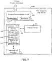
- FIG. 9 illustrates a functional block diagram of at least one embodiment of a user equipment (UE) device 900 with dual active connection capabilities.
- the UE device 900 may generally include a processing circuit 902 (e.g., processor, processing module, etc.) coupled to a memory device 904 (e.g., memory module, memory, etc.), one or more subscriber identity (ID) module(s) 918, and/or and a wireless communication circuit 906 according to some aspects/embodiments.
- a processing circuit 902 e.g., processor, processing module, etc.
- memory device 904 e.g., memory module, memory, etc.
- ID subscriber identity
- the processing circuit 902 may be configured to establish a wireless connection via the wireless communication circuit 906 to send and/or receive information from a network (e.g., from an access node).
- the processing circuit 902 may be coupled to the memory circuit 904 such that the processing circuit 902 can read information from, and write information to, the memory device 904.
- the processing circuit 902 may also include a network connection module/circuit 908 for establishing a network connection (via the wireless communication circuit 906) with one or more access nodes.
- the processing circuit 902 may also include a device authentication module/circuit 910 for performing the various steps of authenticating the user equipment 900 with a network.
- the processing circuit 902 may also include a dual active handover module/circuit 912 for performing a handover from a first access node to a second access node while maintaining two simultaneous active connections during the handover process.
- the UE device 900 may also include one or more subscriber (or user) identity module(s) 918 coupled to the processing circuit 902.
- the subscriber identity module(s) 918 may comprise any subscriber identity module, such as a Subscriber Identification Module (SIM), a Universal Subscriber Identity Module (USIM), a CDMA Subscriber Identification Module (CSIM) or a Removable User Identification Modules (RUIM).
- SIM Subscriber Identification Module
- USIM Universal Subscriber Identity Module
- CCM CDMA Subscriber Identification Module
- RUIM Removable User Identification Modules
- the subscriber identity module may comprise cryptographic subscriber information contained therein, and adapted for use in subscriber authentication procedures.
- the wireless communication circuit 906 may include one or more transmitters 914 and one or more receivers 916.
- the one or more receiver(s) 916 may be configured to allow the user equipment device 900 to maintain two or more active connections with different access nodes during a handover from a first access node to a second access node.
- the processing circuit 902 may be configured to perform any or all of the processes, functions, steps and/or routines related to the various UE devices described FIGS. 1-8 (e.g., UE device 102, 202, 502, 702).
- the term "configured" in relation to the processing circuit 902 may refer to the processing circuit 902 being one or more of adapted, employed, implemented, or programmed to perform a particular process, function, step and/or routine according to various features described herein.
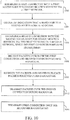
- FIG. 10 is a flow diagram illustrating an example of a method operational in a UE device to facilitate a handover from a first access node to a second access node while maintaining dual active connections according to some aspects/embodiments.
- the UE device may establish a first connection with a first access node for communication services (e.g., data services) via a first network 1002.
- the UE device may then ascertain or receive an indication that a handover to a second access node is to occur 1004.
- the UE device may establish a second connection with a second access node for communication services (e.g., data services), via the first network or a second network, while the first connection remains established 1006.
- the UE device may perform authentication with an entity of the first network.
- both the first connection and second connection are concurrently available, established, and/or active.
- the UE device may receive packets over both the first connection and second connection during handover 1008.
- the UE device may reorder the packets received and delete duplicate packets received during handover 1010. For example, a packet identifier may be used to reorder and/or delete duplicates.
- the UE device may transmit packets over the second connection 1012.
- the UE device may subsequently terminate the first connection once the handover is completed 1014.
- the user equipment device may ascertain or determine to terminate the first connection, e.g., once the second connection becomes fully active.
- the UE device may receive an indication from the first network to terminate the first connection.
- determining when the handover is completed may be based on a message (or indication) received from the first or second access node.
- a handover completed indication may include an end marker (i.e., the last packet from the first node is sent with a flag indicating no more data).
- the handover completed indication may include a radio resource control (RRC) release from the first access node.
- RRC radio resource control
- obtaining an indication that the handover should occur may include receiving a message from the first access node that the handover should occur.
- obtaining an indication that the handover should occur includes making an autonomous decision to initiate the handover.
- the first connection and second connection may be wireless connections over a single radio access network or over different radio access networks.
- the first connection and second connection are established by sharing a single receiver at the user equipment device.
- the first connection is established via a first receiver at the user equipment device and the second connection is established via a second receiver at the user equipment device.
- IP internet protocol
- IP internet protocol
- FIG. 11 illustrates a functional block diagram of at least one embodiment of an access node 1100 that facilitates dual active handovers for user equipment devices.
- the access node 1100 may generally include a processing circuit 1102 (e.g., processor, processing module, etc.) coupled to a memory device 1104 (e.g., memory module, memory, etc.), a network interface circuit 1118, and/or and a wireless communication circuit 1106 according to some aspects/embodiments.
- the processing circuit 1102 may be configured to establish a wireless connection to one or more user equipment devices via the wireless communication circuit 1106.
- the access node 1100 is configured to transmit packets between a wireless network and the network interface circuit 1118 to/from a serving network.
- the processing circuit 1102 may be coupled to the memory circuit 1104 such that the processing circuit 1102 can read information from, and write information to, the memory device 1104.
- the processing circuit 1102 may also include a network connection module/circuit 1108 for establishing a network connection (via the wireless communication circuit 1106) with one or more user equipment devices (UEs).
- the processing circuit 1102 may also include a device authentication module/circuit 1110 for performing the various steps of authenticating the user equipment devices with the serving network.
- the processing circuit 1102 may also include a dual active handover module/circuit 1112 for performing a handover of communication services for a user equipment device to another access node. For instance, if the access node 1100 maintains a first connection with a first user equipment device and decides to handover communication services for the first user equipment device to another access node, it may do so while maintaining first connection active or established until a second connection with the other access node is fully established.
- the wireless communication circuit 1106 may include one or more transmitters 1114 and one or more receivers 1116.
- the processing circuit 1102 may be configured to perform any or all of the processes, functions, steps and/or routines related to the various access node described and/or illustrated in FIGS. 1-8 (e.g., UE device 106, 108, 203, 205, 505, 506, 704, 706).
- the term "configured" in relation to the processing circuit 1102 may refer to the processing circuit 1102 being one or more of adapted, employed, implemented, or programmed to perform a particular process, function, step and/or routine according to various features described herein.
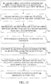
- FIG. 12 illustrates a method operational at a first access node for handing-off wireless services of a user equipment (UE) device to another access node using dual active connections according to some aspects/embodiments.
- a first connection is established between the first access node and a UE device for communication services via a first network 1202.
- the first access node may receive/obtain information from the UE device related to a quality of the first connection 1204.
- the first access node may decide (or alternatively is instructed to) handover the communication services for the UE device to a second access node on a second network 1206.
- a handover request may then be sent by the first access node to initiate the handover 1208. For instance, the handover request may be sent to the second access node (as illustrated in FIG.
- the first access node may continue to receive packets intended for the UE device even after the handover has started 1210.
- the first access node may bicast (e.g., transmitted concurrently, simultaneously, or serially) the packets to both the UE device and the second access node during the handover 1212.
- the first access node may forward the packets to either the UE device or the second access node.
- the first connection may be terminated once the handover is completed 1214.
- FIGS. 1 , 2 , 3 , 4 , 5 , 6 , 7 , 8 , 9 , 10 , 11 and/or 12 may be rearranged and/or combined into a single component, step, feature or function or embodied in several components, steps, or functions. Additional elements, components, steps, and/or functions may also be added without departing from the present disclosure.
- a process is terminated when its operations are completed.
- a process may correspond to a method, a function, a procedure, a subroutine, a subprogram, etc.
- a process corresponds to a function
- its termination corresponds to a return of the function to the calling function or the main function.
- embodiments may be implemented by hardware, software, firmware, middleware, microcode, or any combination thereof.
- the program code or code segments to perform the necessary tasks may be stored in a machine-readable medium such as a storage medium or other storage(s).
- a processor may perform the necessary tasks.
- a code segment may represent a procedure, a function, a subprogram, a program, a routine, a subroutine, a module, a software package, a class, or any combination of instructions, data structures, or program statements.
- a code segment may be coupled to another code segment or a hardware circuit by passing and/or receiving information, data, arguments, parameters, or memory contents. Information, arguments, parameters, data, etc. may be passed, forwarded, or transmitted via any suitable means including memory sharing, message passing, token passing, network transmission, etc.
- a processing circuit may comprise circuitry configured to implement desired programming provided by appropriate media in at least one embodiment.
- a processing circuit may be implemented as one or more of a processor, a controller, a plurality of processors and/or other structure configured to execute executable instructions including, for example, software and/or firmware instructions, and/or hardware circuitry.
- Embodiments of a processing circuit may include a general purpose processor, a digital signal processor (DSP), an application specific integrated circuit (ASIC), a field programmable gate array (FPGA) or other programmable logic component, discrete gate or transistor logic, discrete hardware components, or any combination thereof designed to perform the functions described herein.
- DSP digital signal processor
- ASIC application specific integrated circuit
- FPGA field programmable gate array
- a general purpose processor may be a microprocessor but, in the alternative, the processor may be any conventional processor, controller, microcontroller, or state machine.
- a processor may also be implemented as a combination of computing components, such as a combination of a DSP and a microprocessor, a number of microprocessors, one or more microprocessors in conjunction with a DSP core, or any other such configuration. These examples of the processing circuit are for illustration and other suitable configurations within the scope of the present disclosure are also contemplated.
- memory circuit such as memory device 904 may represent one or more devices for storing programming and/or data, such as processor executable code or instructions (e.g., software, firmware), electronic data, databases, or other digital information.
- a memory circuit may be any available media that can be accessed by a general purpose or special purpose processor.
- memory circuit may include read-only memory (e.g., read-only memory ROM, erasable programmable ROM (EPROM), electrically erasable programmable ROM (EEPROM)), random access memory (RAM), magnetic disk storage mediums, optical storage mediums, flash memory devices, and/or other non-transitory computer-readable mediums for storing information.
- machine-readable medium may include, but are not limited to portable or fixed storage devices, optical storage devices, and various other non-transitory mediums capable of storing, containing or carrying instruction(s) and/or data.
- machine-readable medium may include, but are not limited to portable or fixed storage devices, optical storage devices, and various other non-transitory mediums capable of storing, containing or carrying instruction(s) and/or data.
- various methods described herein may be partially or fully implemented by instructions and/or data that may be stored in a “machine-readable medium”, “computer-readable medium”, and/or “processor-readable medium” and executed by one or more processors, machines and/or devices.
- a software module may reside in RAM memory, flash memory, ROM memory, EPROM memory, EEPROM memory, registers, hard disk, a removable disk, a CD-ROM, or any other form of non-transitory storage medium known in the art.
- a storage medium may be coupled to the processor such that the processor can read information from, and write information to, the storage medium. In the alternative, the storage medium may be integral to the processor.
Description
- Various features disclosed herein relate generally to cellular/wireless communication systems, and at least some features pertain more particularly to methods and devices for facilitating handovers of wireless services (e.g., cellular services) for mobile devices from one access point to another access point. Improvement of handoff procedures can enable and provide efficient use of power resources and aims to improve user experience.
- Mobile devices, such as mobile phones, wireless modems, tablets, or any other device with a processor that communicates with other devices through wireless signals are becoming increasingly popular and are used more frequently. Subscribers using such mobile devices in a cellular/wireless communication network are typically authenticated by the wireless communication network before being granted access to initiate and/or receive calls and transmit and/or receive data.
- During use, mobile devices often move relative to access points such that handing off connections between access points is generally useful to maintain active network connection, as for example described in
EP 2 787 763 A1US 2013/0322347 A1 ,WO 2014/175665 A2 ,EP 2 595 446 A1US 2004/0088641 A1 . Handovers typically involve disconnecting from a first access point prior to connecting to a second access point. During a handover time period, mobile devices cannot send data either over the first wireless connection (because the first wireless connection is terminated) nor over the second wireless connection (because the second wireless connection has not yet been established). - The invention is defined in the appended set of claims.
- The following summarizes some aspects of the present disclosure to provide a basic understanding of the discussed technology. This summary is not an extensive overview of all contemplated features of the disclosure, and is intended neither to identify key or critical elements of all aspects of the disclosure nor to delineate the scope of any or all aspects of the disclosure. Its sole purpose is to present some concepts of one or more aspects of the disclosure in summary form as a prelude to the more detailed description that is presented later.
- Various features facilitate a handover of a communication connection while minimizing service interruptions by using dual active connections at a user equipment device.
- A first aspect provides a method operational on a user equipment device for facilitating a dual active handover. A first connection may be established with a first access node for communication services via a first network. An indication may be obtained that a handover to a second access node is to occur.
- Obtaining an indication that the handover is to occur may include at least one of: (a) receiving a message or indicator from the first access node that the handover is to occur, and/or (b) obtaining an indication that the handover is to occur includes making an autonomous decision by the user equipment device to initiate the handover.
- A second connection may then be established with a second access node for communication services, via the first network or a second network, while the first connection remains established. In various examples, the first connection and second connection may be wireless connections over a single radio access network or over different radio access networks. In another example, the first connection and second connection may be concurrently active during the handover. In yet another example, the first connection and second connection may be established by sharing a single receiver at the user equipment device. In an alternative implementation, the first connection may be established via a first receiver at the user equipment device and the second connection is established via a second receiver at the user equipment device.
- When establishing the second connection, a new internet protocol (IP) address may be created for the user equipment device. Alternatively, a previous internet protocol (IP) address, used by the first connection, may be reused for the user equipment device for the second connection.
- The first connection is terminated once the handover is completed. During handover, packets may be received over both the first connection and second connection. The user equipment may reorder the packets received and deletes duplicate packets received during handover. Also during handover and prior to terminating the first connection, the user equipment may transmitting packets over the second connection.
- Prior to terminating the first connection, the user equipment device may receive handover completed indication from the first access node or second access node. In various examples, the handover completed indication may include at least one of: (a) an end marker indicating no more data to be transmitted; and/or (b) a radio resource control release from the first access node.
- A second aspect provides a user equipment device, comprising: a wireless communication circuit coupled to a processing circuit. The wireless communication circuit may be configured to communicate with a first network. The processing circuit may be configured to: (a) establish a first connection with a first access node for communication services via a first network; (b) obtain an indication that a handover to a second access node is to occur; (c) establish a second connection with a second access node for communication services, via the first network or a second network, while the first connection remains established; and/or (d) terminate the first connection once the handover is completed.
- A third aspect provides a method operational at a first access node for handing over communication services. A first connection may be established between the first access node and a user equipment device for communication services via a first network. A determination is then made to handover the communication services for the user equipment device to a second access node on a second network. The handover determination may be based, at least partially, on information obtained from the user equipment device related to a quality of the first connection. In another example, the handover determination may include receiving an indication that the handover is to occur from the user equipment device.
- A handover request may be sent to initiate the handover. The first access node continues to receive packets intended for the user equipment device even after the handover has started. Those packets may be bicasted from the first access node to both the user equipment device and the second access node during the handover.
- The first connection may be terminated once the handover is completed.
- In one implementation, the first network and the second network may share a common serving gateway (SGW) and Packet Data Network (PDN) gateway (PGW). In another implementation, first network and the second network may each have a different serving gateway (SGW) and Packet Data Network (PDN) gateway (PGW).
- Other aspects, features, and embodiments of the present described herein will become apparent to those of ordinary skill in the art, upon reviewing the following description of specific, exemplary embodiments of the present invention in conjunction with the accompanying figures. While features of the described herein may be discussed relative to certain embodiments and figures below, all embodiments may include one or more of the advantageous features discussed herein. In other words, while one or more embodiments may be discussed as having certain advantageous features, one or more of such features may also be used in accordance with the various embodiments of the invention discussed herein. In similar fashion, while exemplary embodiments may be discussed below as device, system, or method embodiments it should be understood that such exemplary embodiments can be implemented in various devices, systems, and methods.
-
-
FIG. 1 is a diagram illustrating an exemplary next generation communication network architecture, such as an evolved packet system (EPS), according to some aspects/embodiments. -
FIG. 2 is a block diagram illustrating a first example of a handover using dual active connections within a single radio access network with a common mobility management entity (MME) and using a common serving gateway (SGW) and PDN gateway (PGW) according to some aspects/embodiments. -
FIG. 3 is a flow diagram illustrating one example of how a handover using the X2 interface between access nodes may be implemented using dual active connections for a UE within the network environment ofFIG. 2 according to some aspects/embodiments. -
FIG. 4 is a flow diagram illustrating one example of how a handover using the S1 interface between access nodes and the MME and SGW/PGW may be implemented using dual active connections for a UE within the network environment ofFIG. 2 according to some aspects/embodiments. -
FIG. 5 is a block diagram illustrating a second example of a handover using dual active connections across RAN constellations with mobility management entity (MME) relocation and using a common serving gateway (SGW) and PDN gateway (PGW) according to some aspects/embodiments. -
FIG. 6 (comprisingFIGS. 6A and6B ) is a flow diagram illustrating one example of how a handover between access nodes on different RANs with MME relocation and a common SGW/PGW may be implemented using dual active connections for a UE within the network environment ofFIG. 5 according to some aspects/embodiments. -
FIG. 7 is a block diagram illustrating a third example of a handover using dual active connections across RAN constellations with mobility management entity (MME) relocation and using a separate serving gateways (SGW) and PDN gateways (PGW) according to some aspects/embodiments. -
FIG. 8 is a flow diagram illustrating one example of how a handover between access nodes on different RANs with MME relocation and separate SGW/PGWs may be implemented using dual active connections for a UE within the network environment ofFIG. 7 according to some aspects/embodiments. -
FIG. 9 illustrates a functional block diagram of at least one embodiment of a user equipment (UE) device with dual active connection capabilities according to some aspects/embodiments. -
FIG. 10 is a flow diagram illustrating an example of a method operational in a UE device to facilitate a handover from a first access node to a second access node while maintaining dual active connections according to some aspects/embodiments. -
FIG. 11 illustrates a functional block diagram of at least one embodiment of an access node that facilitates dual active handovers for user equipment devices. -
FIG. 12 illustrates a method operational at an access node for handing-off wireless services of a user equipment (UE) device to another access node using dual active connections according to some aspects/embodiments. - In the following description, specific details are given to provide a thorough understanding of the described implementations. However, it will be understood by one of ordinary skill in the art that the implementations may be practiced without these specific details. For example, circuits may be shown in block diagrams in order not to obscure the implementations in unnecessary detail. In other instances, well-known circuits, structures and techniques may be shown in detail in order not to obscure the implementations.
- The word "exemplary" is used herein to mean "serving as an example, instance, or illustration." Any implementation or embodiment described herein as "exemplary" is not necessarily to be construed as preferred or advantageous over other embodiments or implementations. Likewise, the term "embodiments" does not require that all embodiments include the discussed feature, advantage or mode of operation. The term "user equipment" (UE) as used herein is meant to be interpreted broadly. For example, a "user equipment" or "UE" may include a mobile phone, a cellular phone, a smart phone, a session initiation protocol (SIP) phone, a pager, a wireless modem, a personal digital assistant, a personal information manager (PIMs), personal media players, client devices, subscriber devices, tablet computers, laptop computers, a satellite radio, a global positioning system, a multimedia device, a video device, a digital audio player (e.g., MP3 player), a camera, a game console, a tablet, , an entertainment device, a medical device, industrial equipment, actuator/sensor component, automotive component, metering equipment, IoE/IoT devices, and/or other mobile communication/computing devices which communicate, at least partially, through a wireless or cellular network. The term "access node" is also meant to be interpreted broadly, and includes, for example, an evolved Node B (ENB), a base station, a base transceiver station, a radio base station, a radio transceiver, a basic service set (BSS), an extended service set (ESS), a network access point, and/or a network connectivity node that may be part of a radio access network and provides wireless network connectivity to one or more UEs.
- There is a need for methods, apparatus, and/or systems that improve the handover procedure to reduce, minimize or eliminate the lack of data access by a mobile device (e.g., UE) during the handover period.
- A technique is disclosed to minimize service interruption of a wireless user equipment device during a handover from one access node to another access node by maintaining dual active connections during the handover. Upon initiating the handover, an initial/first connection with a first access node is maintained while establishing a second connection with a second access node. The user equipment device can receive data over the first connection and second connection during the handover. The first connection may be terminated (by the user equipment device or by timing out due to inactivity) after the handover is completed.
-
FIG. 1 is a diagram illustrating an exemplary next generation communication network architecture, such as an evolved packet system (EPS) 100, according to some aspects/embodiments. TheEPS 100 may include one or more user equipment (UE) 102, a Radio Access Network (RAN) 104 (e.g., Evolved Universal Mobile Telecommunication System (UMTS) Terrestrial Radio Access Network (E-UTRAN)), an Evolved Packet Core (EPC) 110, a Home Subscriber Server (HSS) 120, and a Packet SwitchedNetwork 122. As shown, theEPS 100 provides packet-switched services, however, as those skilled in the art will readily appreciate, the various concepts presented throughout this disclosure may be extended to networks providing circuit-switched services. - The
RAN 104 may include one or more access nodes A 106 andB 108. Additionally, otheraccess nodes C 109, coupled to other RANs and/or other MMEs may also serve to provide connectivity to theUE 102. As theUE 102 moves, its wireless connection service with thefirst node A 106 may be handed over to anotheraccess node B 108 and/or C 109 (e.g., within the same RAN or different RANs). - In one example, the first
access node A 106 may be connected (or communicatively coupled) to the secondaccess node B 108 via a backhaul interface X2. The firstaccess node A 106 may serve as an access point to theEPC 110 for theUE 102. - The
first access node 106 may be connected by an interface S1 to theEPC 110. TheEPC 110 may include a Mobility Management Entity (MME) 112,other MMEs 114, a Serving Gateway (SGW) 116, and a Packet Data Network (PDN)Gateway 118. TheMME 112 may be the control node that processes signaling between theUE 102 and theEPC 110. Generally, theMME 112 provides bearer and connection management. All user IP packets may be transferred through the Serving Gateway (SGW) 116, which itself is connected to thePDN Gateway 118. ThePDN Gateway 118 may provide the UE internet protocol (IP) address allocation as well as other functions. ThePDN Gateway 118 may be connected to the packet switcheddata network 122. The packet switcheddata network 122 may include the Internet, an intranet, an IP Multimedia Subsystem (IMS), and a PS Streaming Service (PSS). - The access nodes A 106 and
B 108 typically communicate with each other via an "X2" interface. The access nodes A 106 andB 108 communicate with the EPC 110 (including theMME 112 and SGW 116) via an "S1" interface. - In existing wireless communication networks, such as a 4G network or Long Term Evolution (LTE) network, Non-Access Stratum (NAS) protocols form the highest stratum of the control plane between the user equipment (UE) 102 and the
MME 112. NAS protocols support mobility of theUE 102 and the session management procedures to establish and maintain IP connectivity between theUE 102 and aPDN gateway 118. - In one example, the
EPS 100 may utilize an EPS Session Management (ESM) protocol which provides procedures for the handling of EPS bearer contexts. Together with the bearer control provided by the Access Stratum, it provides the control of user plane bearers. The transmission of ESM messages is suspended during EMM procedures except for the attach procedure. - In one example, the
EPS 100 may utilize an EPS Mobility Management (EMM) protocol which provides procedures for the control of mobility when the User Equipment (UE) uses the Evolved UMTS Terrestrial Radio Access Network (E-UTRAN). It also provides control of security for the NAS protocols. - In existing EPS systems, a UE is supported by a single MME at any one time. When a handover occurs across MME boundaries (i.e., from a first MME to a second MME), MME relocation of the UE is required. During this handover, the UE may be left without a data connection. For instance, as the UE switches from a first wireless connection with a first access node (coupled to a first MME) to a second wireless connection with a second access node (coupled to a second MME), there is a period of time in which the first wireless connection is terminated but the second wireless connection is not yet established.
- In next generation networks and according to some aspects/embodiments, as the MME functionality is moved closer to the access nodes, the MME relocation procedures may occur much more frequently. Consequently, loss of connectivity for UE devices may become more noticeable. As described herein, a new procedure is disclosed to optimize handover performance by using dual active connections with different access nodes (e.g., served by different MMEs) to allow the UE to maintain a data connection during a handover.
- As part of providing service to a UE, an MME context per link/connection is setup with an access node for each UE being served. Such MME context is setup between the MME and access node. An MME context may include both an EPS Mobility Management (EMM) context and one or more EPS Session Management (ESM) contexts associated with the UE. An MME context applies to one or more radio access technologies (RATs), e.g., a multi-access MME context including wireless local area network (WLAN) and LTE. The EMM context for a UE is authenticated for access at the network provisioning the credentials used by the UE for attachment (home or visited AAA for roaming), i.e., the access credentials. The access credential function serves to enable service to the UE to be established securely and there may not necessarily be a billing relationship between the access credential provider and the serving network. One or more ESM contexts, where each ESM context is associated with one or more APNs, may be used to host the ESM (session management) functions for each service.
- Some implementations may use more than one MME context simultaneously on a single connection to an access node. The access node may merge or reconcile the two MME contexts for a UE at the RAN and figure out mobility, conflicts, etc., between the two MME contexts. As part of establishing a connection between a UE and access node, a single UE context is typically defined at the access node for the UE. One MME context implies only one identifier, e.g., global unique temporary identifier (GUTI), for the UE context at an access node.
- A UE may have multiple MME contexts active simultaneously when it has multiple links/connections active simultaneously. For example, the UE may be connected over two links to separate access nodes that are not served by the same MME.
- While
FIG. 1 illustrates an exemplary network in which one or more aspects and features may be implemented, these features may also be implemented on various types of networks, including subscriber networks, public data network (PDN) networks, wireless networks, etc. -
FIG. 2 is a block diagram illustrating a first example of a handover using dual active connections within a single radio access network (RAN-A) 204 with a common mobility management entity (MME) 212 and using a common serving gateway (SGW) and PDN gateway (PGW) 208 according to some aspects/embodiments. In this example, a single authentication, authorization, and accounting (AAA)server 216 is used by the UE device 202 (i.e., one subscription is used by the UE device 202). TheUE device 202 may include a transceiver circuit capable of receiving from two different connections, such as two separate receiver circuits or a single receiver circuit that can be shared (e.g., using multiplexing or timeslots) to receive from (and transmit to) two distinct connections. In this example, a handover of theUE device 202 occurs from a first connection via a firstaccess node A 203 and to a second connection via a secondaccess node B 205 while utilizing an X2 interface between the firstaccess node A 203 and secondaccess node B 205. -
FIG. 3 is a flow diagram illustrating one example of how a handover using the X2 interface between access nodes may be implemented using dual active connections for a UE device within the network environment ofFIG. 2 according to some aspects/embodiments. TheUE device 202 may have previously established a first connection or link (e.g., a radio bearer) with the serving firstaccess node A 203. TheUE device 202 may be configured for a dual active connection handover. Upon the occurrence of a triggering event 302 (e.g., receipt of other access node pilot/advertisement, periodic scanning for new access nodes, request from currently serving access node, etc.), theUE device 202 may provide a measurement report 304 (e.g., signal strength measurement, error packet count, etc.) to a currently servingaccess node A 203. The servingaccess node A 203 may make a decision 306 (e.g., based on the measurement report 304) on whether a handover is appropriate. If theaccess node A 203 decides to initiate a handover of connectivity service for theUE device 202 to a different secondaccess node B 205, ahandover request 308 is sent to the secondaccess node B 205 which decides on accepting the request (e.g., as part of admission control 310). If the secondaccess node B 205 determines to accept thehandover request 308, it may send ahandover command 312 to the firstaccess node A 203. Upon receipt of thehandover command 312, the firstaccess node A 203 may send aconnection reconfiguration request 314 to theUE device 202. In response, theUE device 202 may send a connection reconfigurationcomplete message 316 to the firstaccess node A 203, indicating that theUE device 202 shall start the handover to the secondaccess node B 205. The firstaccess node A 203 may then send a handovercomplete message 318 to the secondaccess node B 205. - Upon performing a synchronization with the new cell 320 (e.g., the cell for the second access node B 205) the
UE device 202 may establish a second connection (with the second access node B 205) by sending arandom access preamble 322 to the secondaccess node B 205 and, in reply, receiving arandom access response 328. At this point, theUE device 202 may have two concurrent connections, i.e., the first connection with the firstaccess node A 203 and the second connection with the secondaccess node B 205. - During this handover stage, the first
access node A 203 may buffer packets to theUE device 202 and delivers in-transit packets 330 to the secondaccess node B 205. For instance, the firstaccess node A 203 may send an status transfer message 332 (e.g., to indicate packets for theUE device 202 are being forwarded) to the secondaccess node B 205 and then adata forwarding message 334 including the in-transit packets intended for theUE device 202. That is, the packets arriving at the firstaccess node A 203 for theUE device 202 during the handover procedure may be forwarded to the secondaccess node B 205 which can then deliver them to theUE device 202. Consequently, the secondaccess node B 205 may senddownlink data packets 336 to theUE device 202 while theUE device 202 may senduplink data packets 336 to the secondaccess node B 205, which then forwards 338 them to the PGW/SGW 208. - Note that during this handover, the forwarding of in-transit packets may be in addition to the first
access node A 203 sending the packets directly to theUE device 202. TheUE device 202 may simply discard any duplicate packets received (e.g., packet identifiers may be used to compare packets received from the firstaccess node A 203 and the secondaccess node B 205 and discard duplicate packets). - The second
access node B 205 may initiate a user plane switch (e.g., downlink path for the UE device 202) by sending aswitch request 340 to theMME 212. This notifies theMME 212 that packets to theUE device 202 should be forwarded to the secondaccess node B 205 instead of the firstaccess node A 203. - In turn, the
MME 212 may send a modifybearer request 342 to the PGW/SGW 208. This causes the PGW/SGW 208 to switch thedownlink path 344 for theUE device 202 and send anend marker 346 to the firstaccess node A 203. The firstaccess node A 203 may forward thisend marker 348 to the secondaccess node B 205 to indicate that the secondaccess node B 205 should takeover downlink communications for theUE device 202. Consequently, the secondaccess node B 205 may transmit both uplink anddownlink packet data 350 for theUE device 202. The PGW/SGW 208 may also send a modifybearer response 352 to indicate that the bearer for theUE device 202 has been successfully updated. - After the last buffered
packet 354 has been forwarded by the firstaccess node A 203 to theUE device 202, the firstaccess node A 203 may send aconnection release message 356 to theUE device 202 to terminate the first connection. Additionally, the firstaccess node A 203 may send a UEcontext release request 358 to theMME 212 and receives a UE context release complete 360 in response. Then, the secondaccess node B 205 becomes the only serving node and the dual active handover is completed. - In traditional single active handover, the user plane is disconnected between the connection reconfiguration
complete message 316 and thepacket data messaging 336. However, in dual active handover, the interruption can be avoided by having the firstaccess node A 203 bi-casting cached downlink packet data to theUE device 202 and the secondaccess node B 205. The secondaccess node B 205 forwards the received packet data to theUE device 202. TheUE device 202, due to its dual active capabilities, is able detect and dispose of duplicate packets that may be received. - If an X2 interface is not available between the first
access node A 203 and the secondaccess node B 205, the handover can be performed via an S1 interface. -
FIG. 4 is a flow diagram illustrating one example of how a handover using an S1 interface between access nodes and an MME and SGW/PGW may be implemented using dual active connections for a UE device within the network environment ofFIG. 2 according to some aspects/embodiments. TheUE device 202 may have previously established a first connection with the serving firstaccess node A 203. TheUE device 202 may be configured for a dual active connection handover. Upon the occurrence of a triggering event 402 (e.g., receipt of other access node pilot/advertisement, periodic scanning for new access nodes, request from currently serving access node, etc.), theUE device 202 may provide a measurement report 404 (e.g., signal strength measurement, error packet count, etc.) to a currently servingaccess node A 203. The servingaccess node A 203 may make a decision 406 (e.g., based on the measurement report 404) on whether a handover is appropriate. If theaccess node A 203 decides to initiate a handover of connectivity service for theUE device 202 to a different secondaccess node B 205, a handover requiredmessage 408 is sent to theMME 212. TheMME 212 may then send ahandover request message 410 to the secondaccess node B 205. Upon receipt of thehandover request 410, the secondaccess node B 205 may performadmission control 412 which may result in a handover request acknowledge 414 being sent to theMME 212. If so, theMME 212 may send ahandover command 416 to the firstaccess node A 203. - Upon receipt of the
handover command 416, the firstaccess node A 203 may send aconnection reconfiguration request 418 to theUE device 202. In response, theUE device 202 may send a connection reconfigurationcomplete message 420 to the firstaccess node A 203, indicating that theUE device 202 shall start the handover to the secondaccess node B 205. - Upon performing a synchronization with the new cell 424 (e.g., the cell for the second access node B 205) the
UE device 202 may establish a second connection (with the second access node B 205) by sending arandom access preamble 426 to the secondaccess node B 205 and, in reply, receiving a random access response 428. At this point, theUE device 202 may have two concurrent connections, i.e., the first connection with the firstaccess node A 203 and the second connection with the secondaccess node B 205. - During this handover stage, the first
access node A 203 may buffer packets to theUE device 202 and delivers in-transit packets 430 to the secondaccess node B 205. For instance, the firstaccess node A 203 may send an access node status transfer message 432 (e.g., to indicate packets for theUE device 202 are being forwarded) to theMME 212. In turn, theMME 212 may send an access node status transfer message 434 to the secondaccess node B 205. The firstaccess node A 203 may forwarddata packets 436, including the in-transit packets intended for theUE device 202, to the secondaccess node B 205. That is, the packets arriving at the firstaccess node A 203 for theUE device 202 during the handover procedure may be forwarded to the secondaccess node B 205 which can then deliver them to theUE device 202. Consequently, the secondaccess node B 205 may senddownlink data packets 438 to theUE device 202 while theUE device 202 may senduplink data packets 438 to the secondaccess node B 205, which then forwards 339 them to the PGW/SGW 208. - Note that during this handover, the forwarding of in-transit packets may be in addition to the first
access node A 203 sending the packets directly to theUE device 202. TheUE device 202 may simply discard any duplicate packets received (e.g., packet identifiers may be used to compare packets received from the firstaccess node A 203 and the secondaccess node B 205 and discard duplicate packets). - The second
access node B 205 may send a handover notifymessage 440 to theMME 212. This may indicate to theMME 212 that packets to theUE device 202 should be forwarded to the secondaccess node B 205 instead of the firstaccess node A 203. - In turn, the
MME 212 may send a modify bearer request 442 to the PGW/SGW 208. This causes the PGW/SGW 208 to switch thedownlink path 444 for theUE device 202 and send anend marker 446 to the firstaccess node A 203. The firstaccess node A 203 may forward thisend marker 448 to the secondaccess node B 205 to indicate that the secondaccess node B 205 should takeover downlink communications for theUE device 202. Consequently, the secondaccess node B 205 may transmit both uplink anddownlink packet data 450 for theUE device 202. The PGW/SGW 208 may also send a modifybearer response 452 to indicate that the bearer for theUE device 202 has been successfully updated. - After the last buffered
packet 454 has been forwarded by the firstaccess node A 203 to theUE device 202, the firstaccess node A 203 may send a UEcontext release request 456 to theMME 212. In response, thefirst access node 203 may receive a UE context release complete 458 from theMME 212. The firstaccess node A 203 may then send aconnection release message 460 to theUE device 202 to terminate the first connection. Then, the secondaccess node B 205 becomes the only serving node and the dual active handover is completed. -
FIG. 5 is a block diagram illustrating a second example of a handover using dual active connections acrossRAN constellations server 516 is used by a UE 502 (i.e., one subscription is used by the UE 502). However, the handover occurs from a firstaccess node A 504 in a first radio access network (RAN-A) 510 to a secondaccess node B 506 in a second radio access network (RAN-B) 511. The first RAN-A 510 may have a corresponding first MME-A 512 while the second RAN-B 511 may have a corresponding second MME-B 514. A common SGW/PGW gateway 508 is shared by the first RAN-A 510 and second RAN-B 511. TheUE 502 may include a transceiver circuit capable of receiving from two different connections, such as two separate receiver circuits or a single receiver circuit that can be shared (e.g., using timeslots) to receive from (and transmit to) two distinct connections. In this example, a handover of theUE device 502 occurs from a first connection via thefirst access node 504 and to a second connection via thesecond access node 506. -
FIG. 6 (comprisingFIGS. 6A and6B ) is a flow diagram illustrating one example of how a handover between access nodes on different RANs with MME relocation and a common SGW/PGW may be implemented using dual active connections for a UE device within the network environment ofFIG. 5 according to some aspects/embodiments. TheUE device 502 may have previously establishedservice 602 with the firstaccess node A 504, first MME-A 512, and PGW/SGW 508. This may include establishing/obtaining a first connection with the serving firstaccess node A 504 while using a first MME-A 512 and the SGW/PGW 508 while having afirst UE context 606 at theAAA 516. A dual active connection handover may be triggered 604 autonomously by a UE device decision, or the network may indicate (e.g., in an RRC message for the UE device 502) to establish a new connection (e.g., in a CC Handover command with no context). - Upon occurrence of this triggering
event 604, theUE 502 establishes a second connection with the secondaccess node B 506 by sending arandom access preamble 608 to the secondaccess node B 506 and, in reply, receiving arandom access response 610. IfUE device 502 does not need IP address continuity, theUE device 502 may establish a new PDN connection with the secondaccess node B 506. TheUE device 502 may send ahandover attachment request 612 to the secondaccess node B 506. The secondaccess node B 506 sends an initial UE message 614 (including the handover attachment request 612) to the second MME-B 514 (e.g., the MME serving the second access node B 506). Upon receipt of theinitial UE message 614, the second MME-B 514 sends anupdate location request 616 to theAAA 516 and receives anupdate location acknowledgement 618 from theAAA 516, which includes subscription data for the UE device's second connection. The second MME-B 514 then sends an initialUE context setup 620 to the secondaccess node B 506. The secondaccess node B 506 then sends aconnection setup command 622 to theUE device 502 and, in reply, receives a connection setupcomplete command 624 from theUE device 502. The secondaccess node B 506 then sends an initial UE context setup response to the second MME-B 514. The second MME-B 514 then sends a notifyrequest 628 to theAAA 516 and receives a notifyresponse 630. At this point theAAA 516 updates theUE context 632 for theUE device 502 so that it includes the second MME-B and a GUTI2. Meanwhile, the first connection with the firstaccess node A 504 remains active and operational. - If the
UE device 502 decides to move 634 its connection to the secondaccess node B 506 without PGW/SGW relocation (e.g., it needs IP address continuity), theUE device 502 may send ahandover connectivity request 636 to the second MME-B 514 to transfer its connection to the secondaccess node B 506 via the second MME-B 514. The second MME-B 514 uses in the PGW stored in the subscription data retrieved by the second MME-B 514 to create asession request 640 that is sent to the PGW/SGW 508. The PGW-SGW sends asession response 642 to the second MME-B 514. In turn, the second MME-B 514 sends a modify UE context request 644 to the secondaccess node B 506. This causes the secondaccess node B 506 to send a connection reconfiguration message 646 (which includes or acts as a connection response) to theUE device 502. TheUE device 502 sends a connection reconfigurationcomplete message 648 to the secondaccess node B 506 which causes the secondaccess node B 506 to send a modify UE context acceptmessage 650 to the second MME-B 514. The second MME-B 514 sends a notifyrequest 652 to theAAA 516 and receives a notifyresponse 654 in reply. - For the first connection with the first
access node A 504, thePGW 508 initiates bearer deactivation procedure to release the PDN connection. The PGW/SGW 508 notifies the first MME-A that the connection has moved 656. This may include sending adelete session request 658 to the first MM-A 512. If there are no remaining PDN connections to theUE device 502, the first MME-A 512 performs a detachprocedure 660 with theUE 502 and releases the first connection with the firstaccess node A 504. The first MME-A 512 then sends a delete session response message 662 to the PGW/SGW 508. - To perform the correct handover procedure, the
UE device 502 needs to know whether thesecond access node 506 belongs to a different RAN constellation than the firstaccess node A 504. Where network triggered dual active handover is implemented, an rRRC Connection Reconfiguration can include RAN information in the handover command, e.g., a flag indicating the handover is to a different RAN constellation. Where a UE triggered dual active handover is implemented, theUE device 502 can use a network identifier to determine that the handover is to a different RAN constellation, e.g., PLMN ID, TAC, or a new identifier such as a constellation identifier may be used to distinguish between RANs. -
FIG. 7 is a block diagram illustrating a third example of a handover using dual active connections across a plurality ofRAN constellations server 716 is used by a UE 702 (i.e., a first subscription is used by the UE 702) to obtain service via a first connection established with a firstaccess node A 704 in a first RAN-A 710 using a first MME-A 712 and first SGW/PGW-A 708. A handover may occur to a secondaccess node B 706 in a second RAN-B 711 using a second MME-B 718 and a second SGW/PGW-A 718. - As the
UE 702 moves between the twoRAN constellations 710 and 711 (either for handover or due to multi-connectivity), a new context is established in the second MME-B 718. In the case of handover, after the handover is completed, the first MME-A 712 may remove its context associated with theUE 702. - In the case of
separate GWs - In the case of inter-operator multi-connectivity, the UE 70 may use separate subscriptions on each operator or it may be roaming.
-
FIG. 8 is a flow diagram illustrating one example of how a handover between access nodes on different RANs with MME relocation and separate SGW/PGWs may be implemented using dual active connections for a UE within the network environment ofFIG. 7 according to some aspects/embodiments. TheUE device 702 may have previously establishedservice 802 with the firstaccess node A 704, first MME-A 712, and PGW/SGW 708. This may include establishing/obtaining a first connection with the serving firstaccess node A 704 while using a first MME-A 712 and the SGW/PGW 708 and having afirst UE context 806 at theAAA 716. A dual active connection handover may be triggered 804 autonomously by a UE device decision, or the network may indicate (e.g., in an RRC message for the UE device 502) to establish a new connection (e.g., in a CC Handover command with no context). - Upon occurrence of this triggering
event 804, theUE device 702 establishes a second connection with the secondaccess node B 706 by sending arandom access preamble 808 to the secondaccess node B 706 and, in reply, receiving arandom access response 810. IfUE device 702 does not need IP address continuity, theUE device 702 may establish a new PDN connection with the secondaccess node B 706. TheUE device 702 may send ahandover connection request 812 to the second MME-B 718. The secondaccess node B 706 also sends an initial UE message 814 (including the handover attachment request 812) to the second MME-B 818 (e.g., the MME serving the second access node B 706). Upon receipt of theinitial UE message 814, the second MME-B 514 sends anupdate location request 816 to theAAA 716 and receives anupdate location acknowledgement 818 from theAAA 516, which includes subscription data for the UE device's second connection. The second MME-B 718 then sends a createsession request 820 to the second PGW/SGW 714 and receives, in reply, a createsession response 822. The second MME-B 718 then sends an initial UEcontext setup message 824 to the secondaccess node B 706. The secondaccess node B 706 sends aconnection setup command 826 to theUE device 702. In response, theUE device 702 sends a connection setupcomplete message 828 to the secondaccess node B 706. The secondaccess node B 706 may then send an initial UEcontext setup response 830 to the second MME-B 718. - The second MME-
B 718 then sends a notifyrequest 832 to theAAA 716 and receives a notifyresponse 834. At this point theAAA 716 updates theUE context 836 for theUE device 702 so that it includes the second MME-B and a GUTI2. Meanwhile, the first connection with the firstaccess node A 704 remains active and operational up to this point. The network may release thefirst connection 838 from thefirst access node 704, e.g., theUE device 702 may deactivate the PDN connections with first MME-A 712, or the network may release the first connection due to lack of activity. - Note that, if the
UE device 702 needs IP address continuity, theUE device 702 may perform the procedure illustrated inFIG. 6B . -
FIG. 9 illustrates a functional block diagram of at least one embodiment of a user equipment (UE)device 900 with dual active connection capabilities. TheUE device 900 may generally include a processing circuit 902 (e.g., processor, processing module, etc.) coupled to a memory device 904 (e.g., memory module, memory, etc.), one or more subscriber identity (ID) module(s) 918, and/or and awireless communication circuit 906 according to some aspects/embodiments. - The
processing circuit 902 may be configured to establish a wireless connection via thewireless communication circuit 906 to send and/or receive information from a network (e.g., from an access node). Theprocessing circuit 902 may be coupled to thememory circuit 904 such that theprocessing circuit 902 can read information from, and write information to, thememory device 904. Theprocessing circuit 902 may also include a network connection module/circuit 908 for establishing a network connection (via the wireless communication circuit 906) with one or more access nodes. Theprocessing circuit 902 may also include a device authentication module/circuit 910 for performing the various steps of authenticating theuser equipment 900 with a network. Theprocessing circuit 902 may also include a dual active handover module/circuit 912 for performing a handover from a first access node to a second access node while maintaining two simultaneous active connections during the handover process. - The
UE device 900 may also include one or more subscriber (or user) identity module(s) 918 coupled to theprocessing circuit 902. The subscriber identity module(s) 918 may comprise any subscriber identity module, such as a Subscriber Identification Module (SIM), a Universal Subscriber Identity Module (USIM), a CDMA Subscriber Identification Module (CSIM) or a Removable User Identification Modules (RUIM). The subscriber identity module may comprise cryptographic subscriber information contained therein, and adapted for use in subscriber authentication procedures. - The
wireless communication circuit 906 may include one ormore transmitters 914 and one ormore receivers 916. The one or more receiver(s) 916 may be configured to allow theuser equipment device 900 to maintain two or more active connections with different access nodes during a handover from a first access node to a second access node. - According to one or more features, the
processing circuit 902 may be configured to perform any or all of the processes, functions, steps and/or routines related to the various UE devices describedFIGS. 1-8 (e.g.,UE device processing circuit 902 may refer to theprocessing circuit 902 being one or more of adapted, employed, implemented, or programmed to perform a particular process, function, step and/or routine according to various features described herein. -
FIG. 10 is a flow diagram illustrating an example of a method operational in a UE device to facilitate a handover from a first access node to a second access node while maintaining dual active connections according to some aspects/embodiments. The UE device may establish a first connection with a first access node for communication services (e.g., data services) via afirst network 1002. The UE device may then ascertain or receive an indication that a handover to a second access node is to occur 1004. The UE device may establish a second connection with a second access node for communication services (e.g., data services), via the first network or a second network, while the first connection remains established 1006. As part of this process, the UE device may perform authentication with an entity of the first network. During this handover, both the first connection and second connection are concurrently available, established, and/or active. - The UE device may receive packets over both the first connection and second connection during
handover 1008. The UE device may reorder the packets received and delete duplicate packets received duringhandover 1010. For example, a packet identifier may be used to reorder and/or delete duplicates. During the handover and prior to terminating the first connection, the UE device may transmit packets over thesecond connection 1012. - The UE device may subsequently terminate the first connection once the handover is completed 1014. In one example, the user equipment device may ascertain or determine to terminate the first connection, e.g., once the second connection becomes fully active. In another example, the UE device may receive an indication from the first network to terminate the first connection. In some examples, determining when the handover is completed may be based on a message (or indication) received from the first or second access node. For instance, a handover completed indication may include an end marker (i.e., the last packet from the first node is sent with a flag indicating no more data). In another example, the handover completed indication may include a radio resource control (RRC) release from the first access node.
- In one example, obtaining an indication that the handover should occur may include receiving a message from the first access node that the handover should occur. In another example, obtaining an indication that the handover should occur includes making an autonomous decision to initiate the handover.
- In various examples, the first connection and second connection may be wireless connections over a single radio access network or over different radio access networks.
- In one example, the first connection and second connection are established by sharing a single receiver at the user equipment device.
- In another example, the first connection is established via a first receiver at the user equipment device and the second connection is established via a second receiver at the user equipment device.
- When establishing the second connection, a new internet protocol (IP) address may be created for the user equipment device. Alternatively, when establishing the second connection, a previous internet protocol (IP) address used by the first connect for the user equipment device may be reused.
-
FIG. 11 illustrates a functional block diagram of at least one embodiment of anaccess node 1100 that facilitates dual active handovers for user equipment devices. Theaccess node 1100 may generally include a processing circuit 1102 (e.g., processor, processing module, etc.) coupled to a memory device 1104 (e.g., memory module, memory, etc.), anetwork interface circuit 1118, and/or and awireless communication circuit 1106 according to some aspects/embodiments. - The
processing circuit 1102 may be configured to establish a wireless connection to one or more user equipment devices via thewireless communication circuit 1106. Theaccess node 1100 is configured to transmit packets between a wireless network and thenetwork interface circuit 1118 to/from a serving network. Theprocessing circuit 1102 may be coupled to thememory circuit 1104 such that theprocessing circuit 1102 can read information from, and write information to, thememory device 1104. Theprocessing circuit 1102 may also include a network connection module/circuit 1108 for establishing a network connection (via the wireless communication circuit 1106) with one or more user equipment devices (UEs). Theprocessing circuit 1102 may also include a device authentication module/circuit 1110 for performing the various steps of authenticating the user equipment devices with the serving network. Theprocessing circuit 1102 may also include a dual active handover module/circuit 1112 for performing a handover of communication services for a user equipment device to another access node. For instance, if theaccess node 1100 maintains a first connection with a first user equipment device and decides to handover communication services for the first user equipment device to another access node, it may do so while maintaining first connection active or established until a second connection with the other access node is fully established. - The
wireless communication circuit 1106 may include one ormore transmitters 1114 and one ormore receivers 1116. - According to one or more features, the
processing circuit 1102 may be configured to perform any or all of the processes, functions, steps and/or routines related to the various access node described and/or illustrated inFIGS. 1-8 (e.g.,UE device processing circuit 1102 may refer to theprocessing circuit 1102 being one or more of adapted, employed, implemented, or programmed to perform a particular process, function, step and/or routine according to various features described herein. -
FIG. 12 illustrates a method operational at a first access node for handing-off wireless services of a user equipment (UE) device to another access node using dual active connections according to some aspects/embodiments. A first connection is established between the first access node and a UE device for communication services via afirst network 1202. The first access node may receive/obtain information from the UE device related to a quality of thefirst connection 1204. The first access node may decide (or alternatively is instructed to) handover the communication services for the UE device to a second access node on asecond network 1206. A handover request may then be sent by the first access node to initiate thehandover 1208. For instance, the handover request may be sent to the second access node (as illustrated inFIG. 3 ) or to another network node (as illustrated inFIG. 4 , MME 212). The first access node may continue to receive packets intended for the UE device even after the handover has started 1210. The first access node may bicast (e.g., transmitted concurrently, simultaneously, or serially) the packets to both the UE device and the second access node during thehandover 1212. In an alternative implementation, rather than bicasting the packets, the first access node may forward the packets to either the UE device or the second access node. The first connection may be terminated once the handover is completed 1214. - One or more of the components, steps, features and/or functions illustrated in
FIGS. 1 ,2 ,3 ,4 ,5 ,6 ,7 ,8 ,9 ,10 ,11 and/or 12 may be rearranged and/or combined into a single component, step, feature or function or embodied in several components, steps, or functions. Additional elements, components, steps, and/or functions may also be added without departing from the present disclosure. - Also, it is noted that at least some implementations have been described as a process that is depicted as a flowchart, a flow diagram, a structure diagram, or a block diagram. Although a flowchart may describe the operations as a sequential process, many of the operations can be performed in parallel or concurrently. In addition, the order of the operations may be re-arranged. A process is terminated when its operations are completed. A process may correspond to a method, a function, a procedure, a subroutine, a subprogram, etc. When a process corresponds to a function, its termination corresponds to a return of the function to the calling function or the main function.
- Moreover, embodiments may be implemented by hardware, software, firmware, middleware, microcode, or any combination thereof. When implemented in software, firmware, middleware or microcode, the program code or code segments to perform the necessary tasks may be stored in a machine-readable medium such as a storage medium or other storage(s). A processor may perform the necessary tasks. A code segment may represent a procedure, a function, a subprogram, a program, a routine, a subroutine, a module, a software package, a class, or any combination of instructions, data structures, or program statements. A code segment may be coupled to another code segment or a hardware circuit by passing and/or receiving information, data, arguments, parameters, or memory contents. Information, arguments, parameters, data, etc. may be passed, forwarded, or transmitted via any suitable means including memory sharing, message passing, token passing, network transmission, etc.
- A processing circuit, as described herein (e.g., the
processing circuit 902 and/or 1102), may comprise circuitry configured to implement desired programming provided by appropriate media in at least one embodiment. For example, a processing circuit may be implemented as one or more of a processor, a controller, a plurality of processors and/or other structure configured to execute executable instructions including, for example, software and/or firmware instructions, and/or hardware circuitry. Embodiments of a processing circuit may include a general purpose processor, a digital signal processor (DSP), an application specific integrated circuit (ASIC), a field programmable gate array (FPGA) or other programmable logic component, discrete gate or transistor logic, discrete hardware components, or any combination thereof designed to perform the functions described herein. A general purpose processor may be a microprocessor but, in the alternative, the processor may be any conventional processor, controller, microcontroller, or state machine. A processor may also be implemented as a combination of computing components, such as a combination of a DSP and a microprocessor, a number of microprocessors, one or more microprocessors in conjunction with a DSP core, or any other such configuration. These examples of the processing circuit are for illustration and other suitable configurations within the scope of the present disclosure are also contemplated. - As described herein above, memory circuit, such as
memory device 904 may represent one or more devices for storing programming and/or data, such as processor executable code or instructions (e.g., software, firmware), electronic data, databases, or other digital information. A memory circuit may be any available media that can be accessed by a general purpose or special purpose processor. By way of example and not limitation, memory circuit may include read-only memory (e.g., read-only memory ROM, erasable programmable ROM (EPROM), electrically erasable programmable ROM (EEPROM)), random access memory (RAM), magnetic disk storage mediums, optical storage mediums, flash memory devices, and/or other non-transitory computer-readable mediums for storing information. - The terms "machine-readable medium", "computer-readable medium", and/or "processor-readable medium" may include, but are not limited to portable or fixed storage devices, optical storage devices, and various other non-transitory mediums capable of storing, containing or carrying instruction(s) and/or data. Thus, the various methods described herein may be partially or fully implemented by instructions and/or data that may be stored in a "machine-readable medium", "computer-readable medium", and/or "processor-readable medium" and executed by one or more processors, machines and/or devices.
- The methods or algorithms described in connection with the examples disclosed herein may be embodied directly in hardware, in a software module executable by a processor, or in a combination of both, in the form of processing unit, programming instructions, or other directions, and may be contained in a single device or distributed across multiple devices. A software module may reside in RAM memory, flash memory, ROM memory, EPROM memory, EEPROM memory, registers, hard disk, a removable disk, a CD-ROM, or any other form of non-transitory storage medium known in the art. A storage medium may be coupled to the processor such that the processor can read information from, and write information to, the storage medium. In the alternative, the storage medium may be integral to the processor.
- Those of skill in the art would further appreciate that the various illustrative logical blocks, modules, circuits, and algorithm steps described in connection with the embodiments disclosed herein may be implemented as electronic hardware, computer software, or combinations of both. To clearly illustrate this interchangeability of hardware and software, various illustrative components, blocks, modules, circuits, and steps have been described above generally in terms of their functionality. Whether such functionality is implemented as hardware or software depends upon the particular application and design constraints imposed on the overall system.
- The various features of the disclosure described herein can be implemented in different systems without departing from the disclosure. It should be noted that the foregoing embodiments are merely examples and are not to be construed as limiting the disclosure. The description of the embodiments is intended to be illustrative, and not to limit the scope of the disclosure. As such, the present teachings can be readily applied to other types of apparatuses and many alternatives, modifications, and variations will be apparent to those skilled in the art.
Claims (10)
- A method operational in a system for facilitating a dual active handover, comprising:establishing (1002, 1202) a first connection between a user equipment device and a first access node for communication services via a first network;determining (1206), by the first access node, to handover the communication services for the user equipment device to a second access node;obtaining (1004), at the user equipment device, an indication from the first access node that a handover to the second access node is to occur;establishing (1006) a concurrent second connection between the user equipment device and the second access node for communication services, via the first network or a second network, while the first connection remains established;continuing (1210) to receive, at the first access node, packets intended for the user equipment device even after the handover has started;bicasting (1212) packets from the first access node to both the user equipment device and the second access node during the handover, while the user equipment is concurrently also receiving packets from the second access node over the second connection;receiving (1008), at the user equipment device, packets over both the first connection and the second connection during handover;reordering (1010), at the user equipment device, the packets and delete duplicate packets received during handover;receiving, at the user equipment device, a handover completed indication from the first access node, wherein the handover completed indication includes a radio resource control release;and terminating (1014), by the user equipment device, the first connection once the handover is completed.
- The method of claim 1, wherein obtaining (1004), at the user equipment device, an indication that the handover is to occur includes receiving a message or indicator from the first access node that the handover is to occur.
- The method of claim 1, wherein obtaining (1004), at the user equipment device, an indication that the handover is to occur includes making an autonomous decision by the user equipment device to initiate the handover.
- The method of claim 1, wherein the first connection and second connection are wireless connections over a single radio access network or over different radio access networks.
- The method of claim 1, wherein the second connection is established without packet data network gateway / serving gateway reallocation.
- The method of claim 1, further comprising:obtaining information, at the first access node, from the user equipment device related to a quality of the first connection; and wherein the handover determination is based at least partially on the obtained information.
- A system for facilitating a dual active handover, the system comprising:a user equipment device;a first access node; anda second access node;wherein the user equipment device comprises:a wireless communication circuit configured to communicate with a first and/or second network; anda processing circuit coupled to the wireless communication circuit and configured to:establish a first connection with the first access node for communication services via a first network;obtain an indication that a handover to the second access node is to occur;establish a concurrent second connection with the second access node for communication services, via the first network or a second network, while the first connection remains established;receive packets over both the first connection and the second connection during handover;reorder the packets and delete duplicate packets received during handover;receiving a handover completed indication from the first access node, wherein the handover completed indication includes a radio resource control release;andterminate the first connection once the handover is completed;wherein the first access node comprises:a wireless communication circuit configured to communicate over a first network; anda processing circuit coupled to the wireless communication circuit and configured to:establishing the first connection between the first access node and the user equipment device for communication services via the first network;determining to handover the communication services for the user equipment device to the second access node on the second network;sending the handover request to initiate the handover;continuing to receive packets intended for the user equipment device even after the handover has started;bicasting packets from the first access node to both the user equipment device and the second access node during the handover, while the user equipment is concurrently also receiving packets from the second access node over a second connection;andtransmitting a handover completed indication from the first access node, wherein the handover completed indication includes a radio resource control release.
- The system of claim 7, wherein the first connection and second connection are wireless connections over a single radio access network or over different radio access networks.
- The system of claim 7, wherein the first connection and second connection are concurrently active during the handover.
- The system of claim 7, wherein the processing circuit of the user equipment device is further configured to:
transmit packets over the second connection during the handover.
Priority Applications (1)
| Application Number | Priority Date | Filing Date | Title |
|---|---|---|---|
| EP20181638.6A EP3735035A1 (en) | 2014-12-17 | 2015-09-28 | Handover using dual active connections |
Applications Claiming Priority (2)
| Application Number | Priority Date | Filing Date | Title |
|---|---|---|---|
| PCT/CN2014/094029 WO2016095115A1 (en) | 2014-12-17 | 2014-12-17 | Handover using dual active connections |
| PCT/CN2015/090906 WO2016095584A1 (en) | 2014-12-17 | 2015-09-28 | Handover using dual active connections |
Related Child Applications (2)
| Application Number | Title | Priority Date | Filing Date |
|---|---|---|---|
| EP20181638.6A Division EP3735035A1 (en) | 2014-12-17 | 2015-09-28 | Handover using dual active connections |
| EP20181638.6A Division-Into EP3735035A1 (en) | 2014-12-17 | 2015-09-28 | Handover using dual active connections |
Publications (3)
| Publication Number | Publication Date |
|---|---|
| EP3235292A1 EP3235292A1 (en) | 2017-10-25 |
| EP3235292A4 EP3235292A4 (en) | 2018-05-30 |
| EP3235292B1 true EP3235292B1 (en) | 2020-08-26 |
Family
ID=56125579
Family Applications (2)
| Application Number | Title | Priority Date | Filing Date |
|---|---|---|---|
| EP15869095.8A Active EP3235292B1 (en) | 2014-12-17 | 2015-09-28 | Handover using dual active connections |
| EP20181638.6A Pending EP3735035A1 (en) | 2014-12-17 | 2015-09-28 | Handover using dual active connections |
Family Applications After (1)
| Application Number | Title | Priority Date | Filing Date |
|---|---|---|---|
| EP20181638.6A Pending EP3735035A1 (en) | 2014-12-17 | 2015-09-28 | Handover using dual active connections |
Country Status (7)
| Country | Link |
|---|---|
| US (2) | US10356679B2 (en) |
| EP (2) | EP3235292B1 (en) |
| JP (3) | JP2018503303A (en) |
| KR (2) | KR102223586B1 (en) |
| CN (2) | CN113329462B (en) |
| ES (1) | ES2833411T3 (en) |
| WO (2) | WO2016095115A1 (en) |
Families Citing this family (29)
| Publication number | Priority date | Publication date | Assignee | Title |
|---|---|---|---|---|
| CN109479231B (en) * | 2016-07-22 | 2021-07-02 | 谷歌有限责任公司 | Mobility in multi-network wireless systems |
| CN108024269B (en) * | 2016-11-04 | 2021-05-07 | 中国移动通信有限公司研究院 | Method and device for sending and receiving cell measurement configuration information |
| WO2018126461A1 (en) * | 2017-01-06 | 2018-07-12 | 华为技术有限公司 | Network switching method and related equipment |
| CN110326316B (en) * | 2017-03-24 | 2022-03-08 | 英国电讯有限公司 | Method for operating a network node, network node and readable data carrier |
| US10512004B2 (en) | 2017-04-26 | 2019-12-17 | Motorola Mobility Llc | Indicating status of forwarded data |
| WO2018198963A1 (en) * | 2017-04-27 | 2018-11-01 | 三菱電機株式会社 | Communication system |
| EP3622750B1 (en) | 2017-05-10 | 2022-03-09 | Telefonaktiebolaget LM Ericsson (PUBL) | Methods and apparatus for handover control in a wireless communication network |
| EP3410816A1 (en) * | 2017-05-31 | 2018-12-05 | HTC Corporation | Device and method for handling measurement configuration and signaling radio bearer |
| JP6702916B2 (en) * | 2017-07-04 | 2020-06-03 | キヤノン株式会社 | Communication device, external device, communication device control method, external device control method, and program |
| EP3652986B1 (en) * | 2017-07-13 | 2023-06-14 | Telefonaktiebolaget LM Ericsson (PUBL) | Methods and apparatus for handover control of affiliated communication modules in a wireless communication network |
| CN108882334B (en) * | 2017-08-11 | 2019-11-05 | 华为技术有限公司 | A kind of data transmission method, core network user face equipment and source base station |
| WO2019141687A1 (en) * | 2018-01-19 | 2019-07-25 | Sony Corporation | Method and apparatus for handoff of multiple bearers with differing quality of service levels in a wireless communication system |
| KR102418565B1 (en) * | 2018-03-13 | 2022-07-07 | 삼성전자주식회사 | Method for performing communication and device thereof |
| US11337262B2 (en) | 2018-03-28 | 2022-05-17 | British Telecommunications Public Limited Company | Predictive bearers in a wireless communication network |
| CN111903180B (en) | 2018-03-28 | 2021-08-06 | 英国电讯有限公司 | Method and apparatus for establishing bearer for device in wireless communication network |
| CN111869248B (en) | 2018-03-28 | 2023-06-27 | 英国电讯有限公司 | Method for managing traffic flows through an IPX network, network routing node |
| US10701608B2 (en) * | 2018-03-29 | 2020-06-30 | Charter Communications Operating, Llc | Use of dynamic connection priority information to control network connectivity |
| EP3777461A1 (en) | 2018-03-29 | 2021-02-17 | British Telecommunications public limited company | Dedicated bearer management |
| CN112425203A (en) * | 2018-05-14 | 2021-02-26 | 诺基亚技术有限公司 | Handover control over different connections of a hybrid access user terminal |
| US10542466B1 (en) * | 2018-05-25 | 2020-01-21 | Sprint Communications Company L.P. | Mobile phone authentication in WiFi coverage |
| CN110839267B (en) | 2018-08-17 | 2022-01-28 | 维沃移动通信有限公司 | Service node updating method, terminal equipment and network side equipment |
| CN110839300B (en) * | 2018-08-17 | 2022-02-01 | 维沃移动通信有限公司 | Connection processing method and device |
| CN112586035B (en) | 2018-08-21 | 2023-05-16 | 上海诺基亚贝尔股份有限公司 | Dual connectivity handover |
| EP3772227B1 (en) | 2019-07-29 | 2022-07-13 | British Telecommunications public limited company | Cellular telecommunications network |
| EP3970417B1 (en) | 2019-07-29 | 2022-11-30 | British Telecommunications public limited company | Initiation of transfer of user equipment to base station according to visual data |
| US10659978B1 (en) * | 2019-08-23 | 2020-05-19 | Sprint Spectrum L.P. | Use of UE type as basis to control whether to use blind addition or rather threshold-based addition when configuring dual connectivity |
| US11265943B1 (en) | 2020-10-13 | 2022-03-01 | Sprint Spectrum L.P. | Use of fading as basis to control whether to use blind addition or rather threshold-based addition when configuring dual connectivity |
| WO2022104715A1 (en) * | 2020-11-20 | 2022-05-27 | Nec Corporation | Method, device and computer storage medium of communication |
| EP4256849A1 (en) * | 2021-04-30 | 2023-10-11 | ZTE Corporation | Method, device and computer program product for wireless communication |
Citations (1)
| Publication number | Priority date | Publication date | Assignee | Title |
|---|---|---|---|---|
| US20040088641A1 (en) * | 2000-12-09 | 2004-05-06 | Johan Torsner | Transmission control method in a radio access network implementing an automatic repetition request (aqr) protocol at the base station (aqr) |
Family Cites Families (41)
| Publication number | Priority date | Publication date | Assignee | Title |
|---|---|---|---|---|
| US20040125795A1 (en) * | 2000-02-18 | 2004-07-01 | Corson Mathew S | Telecommunications routing |
| US6999434B1 (en) * | 2000-11-28 | 2006-02-14 | Telcordia Technologies, Inc. | Method, system and circuitry for soft handoff in internet protocol-based code division multiple access networks |
| CN1154377C (en) * | 2001-06-13 | 2004-06-16 | 华为技术有限公司 | Seamless talking switching system and method for global radio mobile communication system |
| JP4036627B2 (en) * | 2001-09-27 | 2008-01-23 | 株式会社エヌ・ティ・ティ・ドコモ | Mobile communication system, mobile communication method, base station, and mobile station |
| JP2004228754A (en) * | 2003-01-21 | 2004-08-12 | Matsushita Electric Ind Co Ltd | Mobile management method and mobile communication system |
| US7843882B2 (en) * | 2004-08-23 | 2010-11-30 | Alcatel-Lucent Usa Inc. | Soft vertical handovers in wireless networks |
| CN100387097C (en) * | 2004-12-30 | 2008-05-07 | 华为技术有限公司 | Soft switching method |
| JP4584319B2 (en) | 2005-01-04 | 2010-11-17 | エスケーテレコム株式会社 | Handover method in a mobile communication network with both asynchronous and synchronous networks |
| JP2006238158A (en) * | 2005-02-25 | 2006-09-07 | Nec Corp | Radio communications system, base station control apparatus, radio terminal, and radio communications method |
| US7826846B2 (en) * | 2005-04-19 | 2010-11-02 | Sk Telecom Co., Ltd. | Hand over method for dual band/dual mode mobile communication terminal |
| CN101204026B (en) * | 2005-04-19 | 2011-11-16 | Sk电信有限公司 | Combining mobile communication system with asynchronous communication network and synchronous communication network having mobile communication terminal switch function and method of switching |
| CN1949918A (en) * | 2005-10-11 | 2007-04-18 | 华为技术有限公司 | Double playing switching method and apparatus under two-layer node network architecture |
| US20070225013A1 (en) * | 2006-03-27 | 2007-09-27 | Motorola, Inc. | Method and apparatus for managing an active set |
| US8599797B2 (en) | 2006-06-16 | 2013-12-03 | Nokia Corporation | Apparatus and method for transferring PDP context information for a terminal in the case of intersystem handover |
| CN100542325C (en) * | 2006-06-22 | 2009-09-16 | 华为技术有限公司 | Method for handover control |
| US7899495B2 (en) | 2006-07-14 | 2011-03-01 | Qualcomm Incorporated | Methods and apparatus for supporting multiple connections |
| JP5011962B2 (en) * | 2006-11-06 | 2012-08-29 | 日本電気株式会社 | Communication service continuation system, communication service continuation method, and program thereof |
| EP2028814A1 (en) * | 2007-08-20 | 2009-02-25 | Alcatel Lucent | Method of performing a handover and corresponding network units |
| EP2040492A1 (en) * | 2007-09-18 | 2009-03-25 | Thomson Licensing | Access network handover for a mobile television system |
| KR101370909B1 (en) * | 2007-10-01 | 2014-03-19 | 엘지전자 주식회사 | Method of Fast Uplink Data Transmission for handover |
| US20090109926A1 (en) * | 2007-10-31 | 2009-04-30 | Qualcomm Incorporated | Methods and systems for in-order delivery during handoff using a timer in mobile communications |
| JP5104260B2 (en) * | 2007-12-04 | 2012-12-19 | 富士通株式会社 | Mobile communication system |
| US20100027503A1 (en) * | 2008-07-31 | 2010-02-04 | Qualcomm Incorporated | Method and apparatus for reducing data loss during handover in a wireless communication system |
| KR101562224B1 (en) * | 2009-04-23 | 2015-10-22 | 삼성전자주식회사 | Apparatus and method for forwarding data for reducing handover interrupt time in wireless communication system |
| US8693367B2 (en) * | 2009-09-26 | 2014-04-08 | Cisco Technology, Inc. | Providing offloads in a communication network |
| US8615241B2 (en) * | 2010-04-09 | 2013-12-24 | Qualcomm Incorporated | Methods and apparatus for facilitating robust forward handover in long term evolution (LTE) communication systems |
| CN101841880B (en) * | 2010-05-14 | 2012-07-04 | 华中科技大学 | LTE and WLAN interconnecting system and switching method |
| US8989087B2 (en) * | 2010-06-15 | 2015-03-24 | Telefonaktiebolaget L M Ericsson (Publ) | Methods and devices for managing radio access in a communication system |
| US8737354B2 (en) * | 2011-01-10 | 2014-05-27 | Alcatel Lucent | Method of data path switching during inter-radio access technology handover |
| JP5796832B2 (en) * | 2011-01-31 | 2015-10-21 | ソフトバンク株式会社 | COMMUNICATION SYSTEM, BASE STATION, AND COMMUNICATION CONTROL METHOD |
| US20120230293A1 (en) * | 2011-03-08 | 2012-09-13 | Edward Grinshpun | Method of performing an inter-technology handoff in a loosely coupled architecture |
| US9949189B2 (en) * | 2011-07-11 | 2018-04-17 | Interdigital Patent Holdings, Inc. | Systems and methods for establishing and maintaining multiple cellular connections and/or interfaces |
| US8706118B2 (en) * | 2011-09-07 | 2014-04-22 | Telefonaktiebolaget L M Ericsson (Publ) | 3G LTE intra-EUTRAN handover control using empty GRE packets |
| US9439214B2 (en) * | 2012-05-31 | 2016-09-06 | Cisco Technology, Inc. | Leveraging multiple access technologies simultaneously |
| US9031511B2 (en) * | 2012-06-13 | 2015-05-12 | All Purpose Networks LLC | Operational constraints in LTE FDD systems using RF agile beam forming techniques |
| WO2014116265A1 (en) * | 2013-01-28 | 2014-07-31 | Blackberry Limited | Handover mechanism in cellular networks |
| CN110087272B (en) * | 2013-02-22 | 2021-10-08 | 三星电子株式会社 | Method and system for providing simultaneous connections between multiple E-node bs and user equipment |
| JP5956065B2 (en) * | 2013-04-05 | 2016-07-20 | 京セラ株式会社 | Base station, user terminal, and processor |
| EP2989849B1 (en) * | 2013-04-23 | 2019-06-05 | LG Electronics Inc. | Method and apparatus for transmitting inactivity indication in wireless communication system |
| CN103944796A (en) * | 2013-11-08 | 2014-07-23 | 北京邮电大学 | Interconnection system and switching method for long term evolution (LTE) and visible light communication (VLC) |
| EP4029508A1 (en) * | 2014-10-10 | 2022-07-20 | Idera Pharmaceuticals, Inc. | Treatment of cancer using tlr9 agonists and checkpoint inhibitors |
-
2014
- 2014-12-17 WO PCT/CN2014/094029 patent/WO2016095115A1/en active Application Filing
-
2015
- 2015-09-28 KR KR1020177016232A patent/KR102223586B1/en active IP Right Grant
- 2015-09-28 CN CN202110647104.1A patent/CN113329462B/en active Active
- 2015-09-28 US US15/524,141 patent/US10356679B2/en active Active
- 2015-09-28 KR KR1020217005626A patent/KR20210025693A/en active Application Filing
- 2015-09-28 EP EP15869095.8A patent/EP3235292B1/en active Active
- 2015-09-28 WO PCT/CN2015/090906 patent/WO2016095584A1/en active Application Filing
- 2015-09-28 ES ES15869095T patent/ES2833411T3/en active Active
- 2015-09-28 EP EP20181638.6A patent/EP3735035A1/en active Pending
- 2015-09-28 JP JP2017531664A patent/JP2018503303A/en active Pending
- 2015-09-28 CN CN201580068518.1A patent/CN107113677B/en active Active
-
2019
- 2019-06-28 US US16/456,563 patent/US20190327659A1/en active Pending
- 2019-12-27 JP JP2019239043A patent/JP2020054009A/en active Pending
-
2021
- 2021-05-17 JP JP2021083063A patent/JP7395539B2/en active Active
Patent Citations (1)
| Publication number | Priority date | Publication date | Assignee | Title |
|---|---|---|---|---|
| US20040088641A1 (en) * | 2000-12-09 | 2004-05-06 | Johan Torsner | Transmission control method in a radio access network implementing an automatic repetition request (aqr) protocol at the base station (aqr) |
Non-Patent Citations (1)
| Title |
|---|
| "UMTS Signaling : UMTS Interfaces, Protocols, Message Flows and Procedures Analyzed and Explained", 1 January 2007, JOHN WILEY & SONS, INCORPORATED, ISBN: 978-1-118-40859-9, article KREHER ET AL: "UMTS Signaling : UMTS Interfaces, Protocols, Message Flows and Procedures Analyzed and Explained", pages: 288 - 300, XP055604612 * |
Also Published As
| Publication number | Publication date |
|---|---|
| JP2020054009A (en) | 2020-04-02 |
| CN107113677B (en) | 2021-06-01 |
| EP3235292A4 (en) | 2018-05-30 |
| WO2016095115A1 (en) | 2016-06-23 |
| ES2833411T3 (en) | 2021-06-15 |
| US20170332301A1 (en) | 2017-11-16 |
| EP3235292A1 (en) | 2017-10-25 |
| EP3735035A1 (en) | 2020-11-04 |
| CN107113677A (en) | 2017-08-29 |
| KR102223586B1 (en) | 2021-03-04 |
| JP7395539B2 (en) | 2023-12-11 |
| US20190327659A1 (en) | 2019-10-24 |
| CN113329462B (en) | 2024-02-02 |
| KR20170098826A (en) | 2017-08-30 |
| JP2018503303A (en) | 2018-02-01 |
| US10356679B2 (en) | 2019-07-16 |
| CN113329462A (en) | 2021-08-31 |
| JP2021119721A (en) | 2021-08-12 |
| WO2016095584A1 (en) | 2016-06-23 |
| KR20210025693A (en) | 2021-03-09 |
Similar Documents
| Publication | Publication Date | Title |
|---|---|---|
| JP7395539B2 (en) | Handover using dual active connections | |
| US11197216B2 (en) | Handling of collision between SR procedure and PDU session establishment procedure for PDU session handover | |
| EP3713370A1 (en) | Wireless communications for communication setup/response | |
| US10368275B2 (en) | Method and apparatus for UE mobility in a small cell system | |
| EP3826422B1 (en) | Resume request followed by release and redirect | |
| EP3479623B1 (en) | Methods for supporting session continuity on per-session basis | |
| US10129802B2 (en) | Layered connectivity in wireless systems | |
| US9723647B2 (en) | Handling a radio link failure in communications | |
| IL259463A (en) | Light-weight radio-resource control (rrc) connection setup in multi-radio access technology (rat) network | |
| KR20150131902A (en) | Method and apparatus for improving voice service quality in mobile wireless communication systems | |
| US9888515B2 (en) | Device, system and method for synchronizing network states during handover between VoLTE and WiFi | |
| KR101843221B1 (en) | Handling call transfer from a cs access network to a ps access network | |
| TW202044874A (en) | Enhancement of feature support after interworking | |
| US11950199B2 (en) | Network node and method performed therein for controlling transmission | |
| GB2511540A (en) | Wireless communication system and method | |
| EP4298825A1 (en) | Managing radio resources and downlink transmission during handover |
Legal Events
| Date | Code | Title | Description |
|---|---|---|---|
| STAA | Information on the status of an ep patent application or granted ep patent |
Free format text: STATUS: THE INTERNATIONAL PUBLICATION HAS BEEN MADE |
|
| PUAI | Public reference made under article 153(3) epc to a published international application that has entered the european phase |
Free format text: ORIGINAL CODE: 0009012 |
|
| STAA | Information on the status of an ep patent application or granted ep patent |
Free format text: STATUS: REQUEST FOR EXAMINATION WAS MADE |
|
| 17P | Request for examination filed |
Effective date: 20170705 |
|
| AK | Designated contracting states |
Kind code of ref document: A1 Designated state(s): AL AT BE BG CH CY CZ DE DK EE ES FI FR GB GR HR HU IE IS IT LI LT LU LV MC MK MT NL NO PL PT RO RS SE SI SK SM TR |
|
| AX | Request for extension of the european patent |
Extension state: BA ME |
|
| DAV | Request for validation of the european patent (deleted) | ||
| DAX | Request for extension of the european patent (deleted) | ||
| A4 | Supplementary search report drawn up and despatched |
Effective date: 20180504 |
|
| RIC1 | Information provided on ipc code assigned before grant |
Ipc: H04W 36/14 20090101AFI20180426BHEP |
|
| STAA | Information on the status of an ep patent application or granted ep patent |
Free format text: STATUS: EXAMINATION IS IN PROGRESS |
|
| 17Q | First examination report despatched |
Effective date: 20190722 |
|
| GRAP | Despatch of communication of intention to grant a patent |
Free format text: ORIGINAL CODE: EPIDOSNIGR1 |
|
| STAA | Information on the status of an ep patent application or granted ep patent |
Free format text: STATUS: GRANT OF PATENT IS INTENDED |
|
| INTG | Intention to grant announced |
Effective date: 20200331 |
|
| GRAS | Grant fee paid |
Free format text: ORIGINAL CODE: EPIDOSNIGR3 |
|
| GRAA | (expected) grant |
Free format text: ORIGINAL CODE: 0009210 |
|
| STAA | Information on the status of an ep patent application or granted ep patent |
Free format text: STATUS: THE PATENT HAS BEEN GRANTED |
|
| AK | Designated contracting states |
Kind code of ref document: B1 Designated state(s): AL AT BE BG CH CY CZ DE DK EE ES FI FR GB GR HR HU IE IS IT LI LT LU LV MC MK MT NL NO PL PT RO RS SE SI SK SM TR |
|
| REG | Reference to a national code |
Ref country code: GB Ref legal event code: FG4D |
|
| REG | Reference to a national code |
Ref country code: CH Ref legal event code: EP |
|
| REG | Reference to a national code |
Ref country code: AT Ref legal event code: REF Ref document number: 1307616 Country of ref document: AT Kind code of ref document: T Effective date: 20200915 Ref country code: CH Ref legal event code: NV Representative=s name: MAUCHER JENKINS PATENTANWAELTE AND RECHTSANWAE, DE |
|
| REG | Reference to a national code |
Ref country code: IE Ref legal event code: FG4D |
|
| REG | Reference to a national code |
Ref country code: DE Ref legal event code: R096 Ref document number: 602015058160 Country of ref document: DE |
|
| REG | Reference to a national code |
Ref country code: SE Ref legal event code: TRGR |
|
| REG | Reference to a national code |
Ref country code: NL Ref legal event code: FP |
|
| REG | Reference to a national code |
Ref country code: LT Ref legal event code: MG4D |
|
| PG25 | Lapsed in a contracting state [announced via postgrant information from national office to epo] |
Ref country code: FI Free format text: LAPSE BECAUSE OF FAILURE TO SUBMIT A TRANSLATION OF THE DESCRIPTION OR TO PAY THE FEE WITHIN THE PRESCRIBED TIME-LIMIT Effective date: 20200826 Ref country code: GR Free format text: LAPSE BECAUSE OF FAILURE TO SUBMIT A TRANSLATION OF THE DESCRIPTION OR TO PAY THE FEE WITHIN THE PRESCRIBED TIME-LIMIT Effective date: 20201127 Ref country code: PT Free format text: LAPSE BECAUSE OF FAILURE TO SUBMIT A TRANSLATION OF THE DESCRIPTION OR TO PAY THE FEE WITHIN THE PRESCRIBED TIME-LIMIT Effective date: 20201228 Ref country code: NO Free format text: LAPSE BECAUSE OF FAILURE TO SUBMIT A TRANSLATION OF THE DESCRIPTION OR TO PAY THE FEE WITHIN THE PRESCRIBED TIME-LIMIT Effective date: 20201126 Ref country code: LT Free format text: LAPSE BECAUSE OF FAILURE TO SUBMIT A TRANSLATION OF THE DESCRIPTION OR TO PAY THE FEE WITHIN THE PRESCRIBED TIME-LIMIT Effective date: 20200826 Ref country code: BG Free format text: LAPSE BECAUSE OF FAILURE TO SUBMIT A TRANSLATION OF THE DESCRIPTION OR TO PAY THE FEE WITHIN THE PRESCRIBED TIME-LIMIT Effective date: 20201126 Ref country code: HR Free format text: LAPSE BECAUSE OF FAILURE TO SUBMIT A TRANSLATION OF THE DESCRIPTION OR TO PAY THE FEE WITHIN THE PRESCRIBED TIME-LIMIT Effective date: 20200826 |
|
| REG | Reference to a national code |
Ref country code: AT Ref legal event code: MK05 Ref document number: 1307616 Country of ref document: AT Kind code of ref document: T Effective date: 20200826 |
|
| PG25 | Lapsed in a contracting state [announced via postgrant information from national office to epo] |
Ref country code: IS Free format text: LAPSE BECAUSE OF FAILURE TO SUBMIT A TRANSLATION OF THE DESCRIPTION OR TO PAY THE FEE WITHIN THE PRESCRIBED TIME-LIMIT Effective date: 20201226 Ref country code: RS Free format text: LAPSE BECAUSE OF FAILURE TO SUBMIT A TRANSLATION OF THE DESCRIPTION OR TO PAY THE FEE WITHIN THE PRESCRIBED TIME-LIMIT Effective date: 20200826 Ref country code: LV Free format text: LAPSE BECAUSE OF FAILURE TO SUBMIT A TRANSLATION OF THE DESCRIPTION OR TO PAY THE FEE WITHIN THE PRESCRIBED TIME-LIMIT Effective date: 20200826 Ref country code: PL Free format text: LAPSE BECAUSE OF FAILURE TO SUBMIT A TRANSLATION OF THE DESCRIPTION OR TO PAY THE FEE WITHIN THE PRESCRIBED TIME-LIMIT Effective date: 20200826 |
|
| PG25 | Lapsed in a contracting state [announced via postgrant information from national office to epo] |
Ref country code: CZ Free format text: LAPSE BECAUSE OF FAILURE TO SUBMIT A TRANSLATION OF THE DESCRIPTION OR TO PAY THE FEE WITHIN THE PRESCRIBED TIME-LIMIT Effective date: 20200826 Ref country code: DK Free format text: LAPSE BECAUSE OF FAILURE TO SUBMIT A TRANSLATION OF THE DESCRIPTION OR TO PAY THE FEE WITHIN THE PRESCRIBED TIME-LIMIT Effective date: 20200826 Ref country code: SM Free format text: LAPSE BECAUSE OF FAILURE TO SUBMIT A TRANSLATION OF THE DESCRIPTION OR TO PAY THE FEE WITHIN THE PRESCRIBED TIME-LIMIT Effective date: 20200826 Ref country code: RO Free format text: LAPSE BECAUSE OF FAILURE TO SUBMIT A TRANSLATION OF THE DESCRIPTION OR TO PAY THE FEE WITHIN THE PRESCRIBED TIME-LIMIT Effective date: 20200826 Ref country code: EE Free format text: LAPSE BECAUSE OF FAILURE TO SUBMIT A TRANSLATION OF THE DESCRIPTION OR TO PAY THE FEE WITHIN THE PRESCRIBED TIME-LIMIT Effective date: 20200826 |
|
| REG | Reference to a national code |
Ref country code: DE Ref legal event code: R097 Ref document number: 602015058160 Country of ref document: DE |
|
| PG25 | Lapsed in a contracting state [announced via postgrant information from national office to epo] |
Ref country code: MC Free format text: LAPSE BECAUSE OF FAILURE TO SUBMIT A TRANSLATION OF THE DESCRIPTION OR TO PAY THE FEE WITHIN THE PRESCRIBED TIME-LIMIT Effective date: 20200826 Ref country code: AL Free format text: LAPSE BECAUSE OF FAILURE TO SUBMIT A TRANSLATION OF THE DESCRIPTION OR TO PAY THE FEE WITHIN THE PRESCRIBED TIME-LIMIT Effective date: 20200826 Ref country code: AT Free format text: LAPSE BECAUSE OF FAILURE TO SUBMIT A TRANSLATION OF THE DESCRIPTION OR TO PAY THE FEE WITHIN THE PRESCRIBED TIME-LIMIT Effective date: 20200826 |
|
| REG | Reference to a national code |
Ref country code: ES Ref legal event code: FG2A Ref document number: 2833411 Country of ref document: ES Kind code of ref document: T3 Effective date: 20210615 |
|
| REG | Reference to a national code |
Ref country code: BE Ref legal event code: MM Effective date: 20200930 |
|
| PG25 | Lapsed in a contracting state [announced via postgrant information from national office to epo] |
Ref country code: SK Free format text: LAPSE BECAUSE OF FAILURE TO SUBMIT A TRANSLATION OF THE DESCRIPTION OR TO PAY THE FEE WITHIN THE PRESCRIBED TIME-LIMIT Effective date: 20200826 Ref country code: LU Free format text: LAPSE BECAUSE OF NON-PAYMENT OF DUE FEES Effective date: 20200928 |
|
| PLBE | No opposition filed within time limit |
Free format text: ORIGINAL CODE: 0009261 |
|
| STAA | Information on the status of an ep patent application or granted ep patent |
Free format text: STATUS: NO OPPOSITION FILED WITHIN TIME LIMIT |
|
| 26N | No opposition filed |
Effective date: 20210527 |
|
| PG25 | Lapsed in a contracting state [announced via postgrant information from national office to epo] |
Ref country code: BE Free format text: LAPSE BECAUSE OF NON-PAYMENT OF DUE FEES Effective date: 20200930 Ref country code: SI Free format text: LAPSE BECAUSE OF FAILURE TO SUBMIT A TRANSLATION OF THE DESCRIPTION OR TO PAY THE FEE WITHIN THE PRESCRIBED TIME-LIMIT Effective date: 20200826 Ref country code: IE Free format text: LAPSE BECAUSE OF NON-PAYMENT OF DUE FEES Effective date: 20200928 |
|
| PG25 | Lapsed in a contracting state [announced via postgrant information from national office to epo] |
Ref country code: TR Free format text: LAPSE BECAUSE OF FAILURE TO SUBMIT A TRANSLATION OF THE DESCRIPTION OR TO PAY THE FEE WITHIN THE PRESCRIBED TIME-LIMIT Effective date: 20200826 Ref country code: MT Free format text: LAPSE BECAUSE OF FAILURE TO SUBMIT A TRANSLATION OF THE DESCRIPTION OR TO PAY THE FEE WITHIN THE PRESCRIBED TIME-LIMIT Effective date: 20200826 Ref country code: CY Free format text: LAPSE BECAUSE OF FAILURE TO SUBMIT A TRANSLATION OF THE DESCRIPTION OR TO PAY THE FEE WITHIN THE PRESCRIBED TIME-LIMIT Effective date: 20200826 |
|
| PG25 | Lapsed in a contracting state [announced via postgrant information from national office to epo] |
Ref country code: MK Free format text: LAPSE BECAUSE OF FAILURE TO SUBMIT A TRANSLATION OF THE DESCRIPTION OR TO PAY THE FEE WITHIN THE PRESCRIBED TIME-LIMIT Effective date: 20200826 |
|
| PGFP | Annual fee paid to national office [announced via postgrant information from national office to epo] |
Ref country code: NL Payment date: 20230810 Year of fee payment: 9 |
|
| PGFP | Annual fee paid to national office [announced via postgrant information from national office to epo] |
Ref country code: IT Payment date: 20230914 Year of fee payment: 9 Ref country code: GB Payment date: 20230810 Year of fee payment: 9 |
|
| PGFP | Annual fee paid to national office [announced via postgrant information from national office to epo] |
Ref country code: SE Payment date: 20230908 Year of fee payment: 9 Ref country code: FR Payment date: 20230807 Year of fee payment: 9 Ref country code: DE Payment date: 20230425 Year of fee payment: 9 |
|
| PGFP | Annual fee paid to national office [announced via postgrant information from national office to epo] |
Ref country code: ES Payment date: 20231011 Year of fee payment: 9 |
|
| PGFP | Annual fee paid to national office [announced via postgrant information from national office to epo] |
Ref country code: CH Payment date: 20231001 Year of fee payment: 9 |