EP3235038B1 - Brennstoffzellenvorrichtung - Google Patents
Brennstoffzellenvorrichtung Download PDFInfo
- Publication number
- EP3235038B1 EP3235038B1 EP15781913.7A EP15781913A EP3235038B1 EP 3235038 B1 EP3235038 B1 EP 3235038B1 EP 15781913 A EP15781913 A EP 15781913A EP 3235038 B1 EP3235038 B1 EP 3235038B1
- Authority
- EP
- European Patent Office
- Prior art keywords
- unit
- functional unit
- fuel cell
- functional
- operating temperature
- Prior art date
- Legal status (The legal status is an assumption and is not a legal conclusion. Google has not performed a legal analysis and makes no representation as to the accuracy of the status listed.)
- Active
Links
Images




Classifications
-
- H—ELECTRICITY
- H01—ELECTRIC ELEMENTS
- H01M—PROCESSES OR MEANS, e.g. BATTERIES, FOR THE DIRECT CONVERSION OF CHEMICAL ENERGY INTO ELECTRICAL ENERGY
- H01M8/00—Fuel cells; Manufacture thereof
- H01M8/06—Combination of fuel cells with means for production of reactants or for treatment of residues
- H01M8/0606—Combination of fuel cells with means for production of reactants or for treatment of residues with means for production of gaseous reactants
- H01M8/0612—Combination of fuel cells with means for production of reactants or for treatment of residues with means for production of gaseous reactants from carbon-containing material
- H01M8/0625—Combination of fuel cells with means for production of reactants or for treatment of residues with means for production of gaseous reactants from carbon-containing material in a modular combined reactor/fuel cell structure
-
- H—ELECTRICITY
- H01—ELECTRIC ELEMENTS
- H01M—PROCESSES OR MEANS, e.g. BATTERIES, FOR THE DIRECT CONVERSION OF CHEMICAL ENERGY INTO ELECTRICAL ENERGY
- H01M8/00—Fuel cells; Manufacture thereof
- H01M8/04—Auxiliary arrangements, e.g. for control of pressure or for circulation of fluids
- H01M8/04007—Auxiliary arrangements, e.g. for control of pressure or for circulation of fluids related to heat exchange
- H01M8/04014—Heat exchange using gaseous fluids; Heat exchange by combustion of reactants
- H01M8/04022—Heating by combustion
-
- H—ELECTRICITY
- H01—ELECTRIC ELEMENTS
- H01M—PROCESSES OR MEANS, e.g. BATTERIES, FOR THE DIRECT CONVERSION OF CHEMICAL ENERGY INTO ELECTRICAL ENERGY
- H01M8/00—Fuel cells; Manufacture thereof
- H01M8/10—Fuel cells with solid electrolytes
- H01M8/12—Fuel cells with solid electrolytes operating at high temperature, e.g. with stabilised ZrO2 electrolyte
- H01M2008/1293—Fuel cells with solid oxide electrolytes
-
- H—ELECTRICITY
- H01—ELECTRIC ELEMENTS
- H01M—PROCESSES OR MEANS, e.g. BATTERIES, FOR THE DIRECT CONVERSION OF CHEMICAL ENERGY INTO ELECTRICAL ENERGY
- H01M8/00—Fuel cells; Manufacture thereof
- H01M8/04—Auxiliary arrangements, e.g. for control of pressure or for circulation of fluids
- H01M8/04007—Auxiliary arrangements, e.g. for control of pressure or for circulation of fluids related to heat exchange
- H01M8/04052—Storage of heat in the fuel cell system
-
- H—ELECTRICITY
- H01—ELECTRIC ELEMENTS
- H01M—PROCESSES OR MEANS, e.g. BATTERIES, FOR THE DIRECT CONVERSION OF CHEMICAL ENERGY INTO ELECTRICAL ENERGY
- H01M8/00—Fuel cells; Manufacture thereof
- H01M8/04—Auxiliary arrangements, e.g. for control of pressure or for circulation of fluids
- H01M8/04007—Auxiliary arrangements, e.g. for control of pressure or for circulation of fluids related to heat exchange
- H01M8/04067—Heat exchange or temperature measuring elements, thermal insulation, e.g. heat pipes, heat pumps, fins
-
- Y—GENERAL TAGGING OF NEW TECHNOLOGICAL DEVELOPMENTS; GENERAL TAGGING OF CROSS-SECTIONAL TECHNOLOGIES SPANNING OVER SEVERAL SECTIONS OF THE IPC; TECHNICAL SUBJECTS COVERED BY FORMER USPC CROSS-REFERENCE ART COLLECTIONS [XRACs] AND DIGESTS
- Y02—TECHNOLOGIES OR APPLICATIONS FOR MITIGATION OR ADAPTATION AGAINST CLIMATE CHANGE
- Y02E—REDUCTION OF GREENHOUSE GAS [GHG] EMISSIONS, RELATED TO ENERGY GENERATION, TRANSMISSION OR DISTRIBUTION
- Y02E60/00—Enabling technologies; Technologies with a potential or indirect contribution to GHG emissions mitigation
- Y02E60/30—Hydrogen technology
- Y02E60/50—Fuel cells
Definitions
- the invention relates to a fuel cell device according to the preamble of patent claim 1.
- a fuel cell device with an integrated gas processor unit which comprises a plurality of functional units.
- US 2014 242485 discloses a fuel cell device with an integrated gas processor unit in which five functional units are coaxially arranged.
- US 2008 081233 also discloses coaxially arranged components of a fuel cell system.
- the invention is based on a fuel cell device with an integrated gas processor unit which has at least one first functional unit with a first rated operating temperature, at least one second functional unit with a second nominal operating temperature, at least one third functional unit with a third nominal operating temperature, at least one fourth functional unit with a fourth rated operating temperature and at least a fifth functional unit having a fifth rated operating temperature.
- the functional units are arranged ordered along at least one direction according to their respective nominal operating temperature.
- a “fuel cell device” should in particular be understood to mean a device which, in particular, forms a component, in particular a functional component, in particular a design and / or functional component, of a fuel cell system or the entire fuel cell system.
- a "gas processor unit” is to be understood as meaning, in particular, a unit which is intended to supply a particularly gaseous fluid upstream of a supply line to an anode and / or to a cathode of a fuel cell unit to prepare and / or recycle a use within a reaction taking place in the fuel cell unit and / or at least one exhaust gas of the reaction taking place in the fuel cell unit.
- a “fuel cell unit” in this context is to be understood in particular as a unit having at least one fuel cell which is provided with at least one chemical energy of at least one, in particular continuously supplied, fuel gas, in particular hydrogen and / or carbon monoxide, and at least one oxidant, in particular To convert oxygen, especially into electrical energy.
- the at least one fuel cell can be designed, in particular, as a solid oxide fuel cell (solid oxide fuel cell, abbreviated to SOFC).
- the at least one fuel cell unit comprises a plurality of fuel cells, which are arranged in particular in a fuel cell stack.
- provided is intended to be understood in particular specially programmed, designed and / or equipped.
- the fact that an object is intended for a specific function should in particular mean that the object fulfills and / or executes this specific function in at least one application and / or operating state.
- a "functional unit” is to be understood in this context, in particular a subunit of the gas processor unit, which is in particular provided to at least contribute to a preparation and / or preparation of the particular gaseous fluid and / or the at least one exhaust gas.
- the gas processor unit comprises in particular a plurality, in particular at least three, in particular different from each other and / or identical to each other trained, functional units.
- the functional units of the gas processor unit are integrated in a common housing of the gas processor unit.
- the functional units can each be designed in particular as a reformer unit, as a post-combustion unit or as a heat exchanger.
- a "reformer unit” should in particular be a chemical-technical unit for at least one, in particular partial or complete, treatment of the natural gas, in particular by steam reforming and / or partial oxidation and / or autothermal reforming, in particular for obtaining at least one Fuel gas and / or a fuel gas-containing gas mixture, to be understood.
- a "afterburning unit” is to be understood as meaning, in particular, a unit which is provided for at least substantially afterburning at least one combustible component of an exhaust gas.
- the afterburning unit is provided, in particular at least substantially oxidize fuel gas contained within an anode exhaust gas of a fuel cell unit.
- the afterburner unit may comprise a catalytic afterburner and / or a diffusion burner and / or a recuperative burner and / or a partially and / or fully premixing burner and / or a pore burner.
- a "heat exchanger” is to be understood as meaning, in particular, a unit which is intended to transfer heat in the direction of a temperature gradient between at least two, in particular fluid streams, in particular in a crossflow mode and / or preferably in a counterflow principle.
- Functional units embodied as heat exchangers are in particular provided for transferring heat from at least one fluid stream, in particular an exhaust gas, preferably an anode exhaust gas of a fuel cell unit, in particular to a natural gas and / or a fuel gas and / or a gas mixture containing fuel gas, which in at least one operating state of an anode
- Fuel cell unit is supplied to transfer and / or heat from at least one fluid stream, in particular an exhaust gas and / or an exhaust gas mixture of the fuel cell unit, to an ambient air, which is supplied in at least one operating state of a cathode of the fuel cell unit.
- the units designed as heat exchangers are each designed as coaxial heat exchangers.
- the anode processor comprises at least one functional unit designed as a reformer unit and at least one functional unit designed as a heat exchanger.
- the anode gas processor comprises two functional units each designed as a heat exchanger.
- An "anode gas processor" is to be understood in particular as meaning a unit which is intended in particular to heat a natural gas and / or a fuel gas and / or a gas mixture containing gas to a reaction temperature and / or the natural gas into a fuel gas and / or a fuel gas mixture convict.
- the anode gas processor may be provided to heat at least a portion of ambient air to a reaction temperature prior to delivery to a cathode of a fuel cell unit.
- a "natural gas” is to be understood as meaning in particular a gas and / or a gas mixture, in particular a natural gas mixture, which comprises at least one alkane, in particular methane, ethane, propane and / or butane.
- the natural gas may have further constituents, such as in particular carbon dioxide and / or Nitrogen and / or oxygen and / or sulfur compounds.
- a further part of the functional units is designed as a cathode gas processor.
- a cathode gas processor is to be understood in particular as meaning a unit which is intended in particular to heat ambient air before being supplied to a cathode of a fuel cell unit to a reaction temperature and / or to postprocess an anode exhaust gas of the fuel cell unit.
- the cathode gas processor may be provided to heat at least a portion of a natural gas and / or a fuel gas and / or a fuel gas-containing gas mixture to a reaction temperature.
- the cathode gas processor comprises at least one functional unit designed as a post-combustion unit and at least one functional unit designed as a heat exchanger.
- a "nominal operating temperature of a functional unit” is to be understood as meaning, in particular, a particularly average process temperature which the respective functional unit has during a particularly steady-state operation.
- the functional units are arranged "arranged along at least one direction according to their respective nominal operating temperature" is to be understood in this context that, in particular starting from a functional unit with a highest nominal temperature or with a lowest nominal temperature along one direction considered the other functional units rising nominal operating temperature or falling nominal operating temperature are arranged.
- the embodiment according to the invention makes it possible to provide a generic fuel cell device with advantageous operating characteristics.
- heat losses, in particular within the gas processor unit can advantageously be minimized.
- thermo-mechanical stresses can advantageously be reduced within the functional units, as a result of which a service life can advantageously be increased.
- an advantageously high integration density of components in the gas processor unit can be achieved, whereby in particular a space can be advantageously reduced.
- the functional unit with the highest nominal operating temperature is arranged centrally within the gas processor unit.
- the functional unit with the highest rated operating temperature "is arranged centrally within the gas processor unit” should be understood in particular that a central axis of the gas processor unit at least substantially corresponds to a central axis of the functional unit with the highest rated operating temperature.
- the functional unit with the highest rated operating temperature is designed as a post-combustion unit. As a result, heat losses can advantageously be further reduced.
- the functional units are arranged at least in sections, in the form of a shell around the functional unit with the highest rated operating temperature.
- the at least one part of the functional units is arranged around the functional unit with the highest rated operating temperature such that the nominal operating temperatures of the functional units are arranged in a shell-like manner around the functional unit with the highest rated operating temperature the functional unit with the highest nominal operating temperature surrounding functional units with increasing in particular radial distance from which decrease the functional unit with the highest rated operating temperature.
- At least a part of the functional units is arranged axially next to one another.
- the at least one part of the functional units has at least substantially the same radial distance to a central axis of the functional unit with the highest nominal operating temperature and at least one of them substantially Parallel to the central axis extending straight lines are arranged offset from one another.
- functional units can advantageously be arranged with respect to a temperature distribution within the functional unit having the highest rated operating temperature.
- the fuel cell device comprises at least one fuel cell unit which is at least partially integrated into the gas processor unit.
- the fuel cell unit is at least partially and preferably completely integrated in a housing of the gas processor unit.
- the fuel cell unit is integrated into the gas processor unit such that a center axis of the fuel cell unit corresponds at least substantially to a central axis of the gas processor unit and / or the functional unit with the highest nominal operating temperature.
- at least some of the functional units at least partially surround the fuel cell unit.
- the fuel cell unit can advantageously be integrated in particular thermally into the gas processor unit.
- the gas processor unit is at least essentially cylindrical, an advantageously symmetrical temperature propagation within the gas processor unit can be achieved.
- the gas processor unit has an at least substantially circular base area.
- the gas processor unit has a base surface deviating from a circular shape.
- the gas processor unit may have a simple regular polygonal base.
- the fuel cell device according to the invention should not be limited to the application and embodiment described above.
- the fuel cell device according to the invention may have a different number from a number of individual elements, components and units mentioned herein for fulfilling a mode of operation described herein.
- the fuel cell device 34 comprises a gas processor unit 10 with five functional units 12, 14, 16, 18, 20, wherein a part of the functional units 12, 14 forms a cathode gas processor 36 and another part of the functional units 16 , 18, 20 forms an anode gas processor 38.
- the functional units 12, 14, 16, 18, 20 each have a specific nominal operating temperature.
- the cathode gas processor 36 comprises a first functional unit 12 designed as a afterburning unit 24 and a second functional unit 14 designed as a heat exchanger 26.
- the anode gas processor 38 comprises a third functional unit 16 and a fifth functional unit 20, which are each designed as a heat exchanger 28, 30.
- the anode gas processor 38 comprises a fourth functional unit 18 designed as a reformer unit 22, which is connected between the third functional unit 16 and the fifth functional unit 20.
- the first functional unit 12 designed as a afterburning unit 24 has the highest nominal operating temperature compared with the remaining functional unit 14, 16, 18, 20.
- the fuel cell device 34 has a fuel cell unit 32.
- the fuel cell unit 32 is shown here in simplified form as a fuel cell 40 for generating electrical and thermal energy.
- the electrical energy can be tapped via two DC lines 42, 44.
- a design of a fuel cell unit as a fuel cell stack with a plurality of fuel cells is conceivable.
- the fuel cell 40 is preferably designed as a solid oxide fuel cell.
- the fuel cell 40 has an anode 46 and a cathode 48.
- a fresh gas is supplied to the fuel cell device 34 via a process connection 50.
- the fresh gas consists of fresh natural gas and a recirculate, which is discharged via a further process connection 52 from the fuel cell device 34.
- the natural gas and the recirculate are combined outside the fuel cell device 34 and compressed by means of a compressor 54.
- the fresh gas is preheated in the third functional unit 16 by an anode exhaust gas of the fuel cell unit 32.
- the third functional unit 16 may be preceded by a desulfurization unit, not shown here, in particular a hot desulfurization unit. It is then passed through the fourth functional unit 18 into the fifth functional unit 20, where it is heated to a reaction temperature between 650 ° C and 850 ° C.
- the fourth functional unit 18 serves for an endothermic steam reforming of the long-chain alkanes present in natural gas (C x H 2 (x + 1) , where x> 1): C x H 2 (x + 1) + x * H 2 O ⁇ x * CO + (2x + 1) * H 2
- the fuel gas-containing reformate obtained by the fourth functional unit 18 is supplied to the anode 46 of the fuel cell unit 32, where it is converted by an electrochemical reaction to generate electrical and thermal energy.
- a hot anode exhaust gas of the fuel cell unit 32 is directed to the fifth functional unit 20 to heat the fresh gas to the reaction temperature. Since the fresh gas is not completely convertible in the anode 46 of the fuel cell unit 32, a part of the anode exhaust gas, as already described, the fresh natural gas is supplied as a recirculate. The remainder of the anode exhaust gas is fed directly to the first functional unit 12. In the first functional unit 12 combustible constituents of the anode exhaust gas are post-combusted. The resulting in the first functional unit 12 Heat is used to heat one of the fuel cell device 34 supplied via a process connection 56 ambient air for the cathode 48 and, for example, heating heating water to another process connection 58 (not shown here).
- the ambient air in the second functional unit 14 is heated to the reaction temperature.
- a cathode exhaust gas is passed directly into the first functional unit 12.
- natural gas may be supplied to the first functional unit 12 via a conduit 60. This may be necessary, above all, during a heating process of the fuel cell device 34.
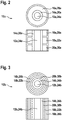
- FIG. 2 shows in a highly simplified schematic diagram an arrangement of the functional units 12a, 14a, 16a, 18a, 20a within the gas processor unit 10a in a side view and in a plan view.
- the gas processor unit 10a is cylindrical. Alternatively, a gas processor unit may also have an outer contour deviating from a cylindrical shape.
- the functional units 12a, 14a, 16a, 18a, 20a are arranged within the gas processor unit 10a according to their respective nominal operating temperature.
- the first functional unit 12a with the highest rated operating temperature, designed as a post-combustion unit 24a, is arranged centrally within the gas processor unit 10a.
- the first functional unit 12a is completely enclosed in the circumferential direction by the second functional unit 14a.
- the third functional unit 16a, the fourth functional unit 18a and the fifth functional unit 20a respectively surround the first functional unit 12a and the second functional unit 14a in the circumferential direction.
- the third functional unit 16a, the fourth functional unit 18a and the fifth functional unit 20a are arranged axially next to one another.
- hot gas flows within the first functional unit 12a from bottom to top.
- a gas temperature within the first functional unit 12a decreases with increasing altitude.
- a rotationally symmetrical temperature distribution within the first functional unit 12a and the second functional unit 14a is established.
- a temperature level of an outer wall of the second functional unit 14a decreases with increasing height. Since the nominal operating temperatures of the third functional unit 16a, the fourth functional unit 18a and the fifth functional unit 20a increase in series, these are mutually about the second functional unit 14a arranged.
- the fifth functional unit 20a has the highest rated operating temperature with respect to the third functional unit 16a and the fourth functional unit 18a and is accordingly arranged at the bottom.
- the third functional unit 16a has the lowest rated operating temperature compared with the fourth functional unit 18a and the fifth functional unit 20a and is accordingly arranged at the top.
- the fourth functional unit 18a is arranged between the third functional unit 16a and the fifth functional unit 20a.
- FIGS. 3 to 10 eight further non-inventive embodiments are shown.
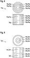
- FIG. 3 shows in a highly simplified schematic diagram an alternative arrangement of functional units 12b, 14b, 16b, 18b, 20b within a gas processor unit 10b in a side view and in a plan view.
- the gas processor unit 10b is cylindrical. Alternatively, a gas processor unit may also have an outer contour deviating from a cylindrical shape.
- the functional units 12b, 14b, 16b, 18b, 20b are disposed within the gas processor unit according to their respective nominal operating temperature.
- the first functional unit 12b with the highest rated operating temperature, designed as a post-combustion unit 24b, is arranged centrally within the gas processor unit 10b.
- the further functional units 14b, 16b, 18b, 20b are arranged in a cup shape with decreasing nominal operating temperature from the inside to the outside around the first functional unit 12b.
- FIG. 4 shows in a highly simplified schematic diagram, another alternative arrangement of functional units 12c, 14c, 16c, 18c, 20c within a gas processing unit 10c in a side view and in a plan view.
- the gas processor unit 10c is cylindrical. Alternatively, a gas processor unit may also have an outer contour deviating from a cylindrical shape.
- the functional units 12c, 14c, 16c, 18c, 20c are within the gas processor unit 10c according to their respective ones Rated operating temperature arranged.
- the first functional unit 12c with the highest rated operating temperature which is designed as a post-combustion unit 24c, is arranged centrally within the gas processor unit 10c.
- the first functional unit 12c is completely enclosed in the circumferential direction by the second functional unit 14c.
- the third functional unit 16c and the fifth functional unit 20c surround the first functional unit 12c and the second functional unit 14c in the form of a shell.
- the fourth functional unit 18c is arranged axially next to the third functional unit 16c and the fifth
- FIG. 5 shows in a highly simplified schematic diagram, a further alternative arrangement of functional units 12d, 14d, 16d, 18d, 20d within a gas processor unit 10d in a side view and in a plan view.
- the gas processor unit 10d is cylindrical. Alternatively, a gas processor unit may also have an outer contour deviating from a cylindrical shape.
- the functional units 12d, 14d, 16d, 18d, 20d are disposed within the gas processor unit 10d according to their respective rated operating temperature.
- the first functional unit 12d with the highest nominal operating temperature, designed as the afterburning unit 24d, is arranged centrally within the gas processor unit 10d.
- the second functional unit 14d and the fourth functional unit 18d are arranged around the first functional unit 12d.
- the third functional unit 16d and the fifth functional unit 20d are arranged axially next to one another and in each case partially surround the first functional unit 12d and the second functional unit 14d.
- FIG. 6 shows in a highly simplified schematic diagram of a gas processing unit 10e in which in addition to functional units 12e, 14e, 16e, 18e, 20e further a fuel cell unit 32e is integrated into the gas processor unit 10e.
- the arrangement of the functional units 12e, 14e, 16e, 18e, 20e corresponds to that in the FIG. 2 shown arrangement.
- the fuel cell unit 32e is arranged centrally below the first functional unit 12e.
- the fuel cell unit 32e is completely enclosed in the circumferential direction by the fifth functional unit 20e.
- FIG. 7 shows in a highly simplified schematic diagram of an alternative gas processor unit 10f in which, in addition to functional units 12f, 14f, 16f, 18f, 20f, a fuel cell unit 32f is integrated into the gas processor unit 10f.
- the arrangement of the functional units 12f, 14f, 16f, 18f, 20f corresponds to that in FIG FIG. 2 shown arrangement.
- the fuel cell unit 32f is centrally below the first functional unit 12f arranged.
- the fuel cell unit 32f is completely enclosed in the circumferential direction by the second functional unit 14f.
- FIG. 8 shows in a highly simplified schematic diagram of another alternative gas processor unit 10g in which in addition to functional units 12g, 14g, 16g, 18g, 20g further a fuel cell unit 32g is integrated into the gas processor unit 10g.
- the arrangement of the functional units 12g, 14g, 16g, 18g, 20g corresponds to that in the FIG. 3 shown arrangement.
- the fuel cell unit 32g is arranged centrally below the first functional unit 12g.
- the further functional units 14g, 16g, 18g, 20g are arranged shell-shaped with decreasing nominal operating temperature from the inside to the outside around the first functional unit 12g and the fuel cell unit 32g.
- FIG. 9 shows in a highly simplified schematic diagram of another alternative gas processor unit 10h in which in addition to functional units 12h, 14h, 16h, 18h, 20h further a fuel cell unit 32h is integrated into the gas processor unit 10h.
- the arrangement of the functional units 12 h, 14 h, 16 h, 18 h, 20 h corresponds to that in the FIG. 4 shown arrangement.
- the fuel cell unit 32h is arranged centrally below the first functional unit 12h.
- the fuel cell unit 32h is completely enclosed in the circumferential direction by the second functional unit 14h.
- FIG. 10 shows in a highly simplified schematic diagram of another alternative gas processor unit 10i in which in addition to functional units 12i, 14i, 16i, 18i, 20i further includes a fuel cell unit 32i is integrated into the gas processor unit 10i.
- the arrangement of the functional units 12i, 14i, 16i, 18i, 20i corresponds to that in the FIG. 5 shown arrangement.
- the fuel cell unit 32i is arranged centrally below the first functional unit 12i.
- the fuel cell unit 32i is completely enclosed in the circumferential direction by the second functional unit 14i.
Landscapes
- Engineering & Computer Science (AREA)
- Chemical & Material Sciences (AREA)
- Life Sciences & Earth Sciences (AREA)
- Manufacturing & Machinery (AREA)
- Sustainable Development (AREA)
- Sustainable Energy (AREA)
- Chemical Kinetics & Catalysis (AREA)
- Electrochemistry (AREA)
- General Chemical & Material Sciences (AREA)
- Combustion & Propulsion (AREA)
- Fuel Cell (AREA)
Description
- Die Erfindung betrifft eine Brennstoffzellenvorrichtung nach dem Oberbegriff des Patentanspruchs 1.
- Es ist bereits eine Brennstoffzellenvorrichtung mit einer integrierten Gasprozessoreinheit bekannt, welche eine Mehrzahl von Funktionseinheiten umfasst.
-
US 2014 242485 offenbart eine Brennstoffzellenvorrichtung mit einer integrierten Gasprozessoreinheit bei der fünf Funktionseinheiten koaxial angeordnet sind. -
US 2008 081233 offenbart ebenfalls koaxial angeordnete Komponenten eines Brennstoffzellensystems. - Die Erfindung geht aus von einer Brennstoffzellenvorrichtung mit einer integrierten Gasprozessoreinheit, welche zumindest eine erste Funktionseinheit mit einer ersten Nennbetriebstemperatur, zumindest eine zweite Funktionseinheit mit einer zweiten Nennbetriebstemperatur, zumindest eine dritte Funktionseinheit mit einer dritten Nennbetriebstemperatur, zumindest eine vierte Funktionseinheit mit einer vierten Nennbetriebstemperatur und zumindest eine fünfte Funktionseinheit mit einer fünften Nennbetriebstemperatur aufweist.
- Es wird vorgeschlagen, dass die Funktionseinheiten entlang zumindest einer Richtung betrachtet gemäß ihrer jeweiligen Nennbetriebstemperatur geordnet angeordnet sind.
- Unter einer "Brennstoffzellenvorrichtung" soll insbesondere eine Vorrichtung verstanden werden, welche insbesondere einen, insbesondere funktionstüchtiger, Bestandteil, insbesondere eine Konstruktions- und/oder Funktionskomponente, eines Brennstoffzellensystems oder das gesamte Brennstoffzellensystem ausbildet. Unter einer "Gasprozessoreinheit" soll in diesem Zusammenhang insbesondere eine Einheit verstanden werden, welche dazu vorgesehen ist, ein insbesondere gasförmiges Fluid vor einer Zuleitung zu einer Anode und/oder zu einer Kathode einer Brennstoffzelleneinheit für eine Verwendung innerhalb einer in der Brennstoffzelleneinheit ablaufenden Reaktion und/oder zumindest ein Abgas der in der Brennstoffzelleneinheit ablaufenden Reaktion aufzubereiten und/oder nachzubereiten. Unter einer "Brennstoffzelleneinheit" soll in diesem Zusammenhang insbesondere eine Einheit mit zumindest einer Brennstoffzelle verstanden werden, welche dazu vorgesehen ist, zumindest eine chemische Energie zumindest eines, insbesondere kontinuierlich zugeführten, Brenngases, insbesondere Wasserstoff und/oder Kohlenstoffmonoxid, und zumindest eines Oxidationsmittels, insbesondere Sauerstoff, insbesondere in elektrische Energie umzuwandeln. Die zumindest eine Brennstoffzelle kann insbesondere als Festoxid-Brennstoffzelle (engl. Solid Oxide Fuel Cell, abgek. SOFC) ausgebildet sein. Vorzugsweise umfasst die zumindest eine Brennstoffzelleneinheit eine Vielzahl von Brennstoffzellen, welche insbesondere in einem Brennstoffzellenstack angeordnet sind. Unter "vorgesehen" soll insbesondere speziell programmiert, ausgelegt und/oder ausgestattet verstanden werden. Darunter, dass ein Objekt zu einer bestimmten Funktion vorgesehen ist, soll insbesondere verstanden werden, dass das Objekt diese bestimmte Funktion in zumindest einem Anwendungs- und/oder Betriebszustand erfüllt und/oder ausführt.
- Unter einer "Funktionseinheit" soll in diesem Zusammenhang insbesondere eine Teileinheit der Gasprozessoreinheit verstanden werden, welche insbesondere dazu vorgesehen ist, zumindest einen Beitrag zu einer Aufbereitung und/oder Vorbereitung des insbesondere gasförmigen Fluids und/oder des zumindest einen Abgases zu leisten. Die Gasprozessoreinheit umfasst insbesondere eine Mehrzahl, insbesondere zumindest drei, insbesondere verschieden voneinander und/oder identisch zueinander ausgebildeter, Funktionseinheiten. Insbesondere sind die Funktionseinheiten der Gasprozessoreinheit in ein gemeinsames Gehäuse der Gasprozessoreinheit integriert. Die Funktionseinheiten können jeweils insbesondere als eine Reformereinheit, als eine Nachbrenneinheit oder als ein Wärmeübertrager ausgebildet sein. Unter einer "Reformereinheit" soll in diesem Zusammenhang insbesondere eine chemischtechnische Einheit zu zumindest einer, insbesondere teilweisen oder vollständigen, Aufbereitung des Erdgases, insbesondere durch eine Dampfreformierung und/oder durch eine partielle Oxidation und/oder durch eine autotherme Reformierung, insbesondere zur Gewinnung zumindest eines Brenngases und/oder eines brenngashaltigen Gasgemischs, verstanden werden. Unter einer "Nachbrenneinheit" soll in diesem Zusammenhang insbesondere eine Einheit verstanden werden, welche dazu vorgesehen ist, zumindest einen brennbaren Bestandteil eines Abgases zumindest weitgehend nachzuverbrennen. Vorzugsweise ist die Nachbrenneinheit dazu vorgesehen, insbesondere innerhalb eines Anodenabgases einer Brennstoffzelleneinheit enthaltenes Brenngas zumindest weitgehend zu oxidieren. Insbesondere kann die Nachbrenneinheit einen katalytischen Nachbrenner und/oder einen Diffusionsbrenner und/oder einen Rekuperatorbrenner und/oder einen teil- und/oder vollvormischenden Brenner und/oder einen Porenbrenner umfassen. Unter einem "Wärmeübertrager" soll in diesem Zusammenhang insbesondere eine Einheit verstanden werden, welche dazu vorgesehen ist, Wärme in Richtung eines Temperaturgefälles zwischen zumindest zwei insbesondere fluiden Stoffströmen zu übertragen, insbesondere in einem Kreuzstrombetrieb und/oder vorzugsweise in einem Gegenstromprinzip. Als Wärmeübertrager ausgebildete Funktionseinheiten sind insbesondere dazu vorgesehen, Wärme von zumindest einem fluiden Stoffstrom, insbesondere einem Abgas, vorzugsweise einem Anodenabgas einer Brennstoffzelleneinheit, insbesondere auf ein Erdgas und/oder ein Brenngas und/oder ein brenngashaltiges Gasgemisch, welches in zumindest einem Betriebszustand einer Anode der Brennstoffzelleneinheit zugeführt wird, zu übertragen und/oder eine Wärme von zumindest einem fluiden Stoffstrom, insbesondere einem Abgas und/oder einem Abgasgemisch der Brennstoffzelleneinheit, auf eine Umgebungsluft, welche in zumindest einem Betriebszustand einer Kathode der Brennstoffzelleneinheit zugeführt ist, zu übertragen. Vorzugsweise sind die als Wärmeübertrager ausgebildeten Einheiten jeweils als Koaxialwärmeübertrager ausgebildet.
- Insbesondere ist zumindest ein Teil der Funktionseinheiten Teil eines Anodengasprozessors. Insbesondere umfasst der Anodenprozessor zumindest eine als eine Reformereinheit ausgebildete Funktionseinheit und zumindest eine als eine Wärmeübertrager ausgebildete Funktionseinheit. Vorzugsweise umfasst der Anodengasprozessor zwei jeweils als ein Wärmeübertrager ausgebildete Funktionseinheiten. Unter einem "Anodengasprozessor" soll insbesondere eine Einheit verstanden werden, welche dazu vorgesehen ist, insbesondere ein Erdgas und/oder ein Brenngas und/oder ein brenngashaltiges Gasgemisch auf eine Reaktionstemperatur zu erwärmen und/oder das Erdgas in ein Brenngas und/oder ein Brenngasgemisch zu überführen. Alternativ oder zusätzlich kann der Anodengasprozessor dazu vorgesehen sein, zumindest einen Teil einer Umgebungsluft vor einer Zuführung an eine Kathode einer Brennstoffzelleneinheit auf eine Reaktionstemperatur zu erwärmen. Unter einem "Erdgas" soll in diesem Zusammenhang insbesondere ein Gas und/oder ein Gasgemisch, insbesondere ein Naturgasgemisch, verstanden werden, welches zumindest ein Alkan, insbesondere Methan, Ethan, Propan und/oder Butan, umfasst. Ferner kann das Erdgas weitere Bestandteile aufweisen, wie insbesondere Kohlenstoffdioxid und/oder Stickstoff und/oder Sauerstoff und/oder Schwefelverbindungen. Insbesondere ist ein weiterer Teil der Funktionseinheiten als ein Kathodengasprozessor ausgebildet. Insbesondere ist zumindest ein weiterer Teil der Funktionseinheiten Teil eines Kathodengasprozessors. Unter einem "Kathodengasprozessor" soll insbesondere eine Einheit verstanden werden, welche dazu vorgesehen ist, insbesondere eine Umgebungsluft vor einer Zuführung an eine Kathode einer Brennstoffzelleneinheit auf eine Reaktionstemperatur zu erwärmen und/oder ein Anodenabgas der Brennstoffzelleneinheit nachzubereiten. Alternativ oder zusätzlich kann der Kathodengasprozessor dazu vorgesehen sein, zumindest einen Teil eines Erdgases und/oder eines Brenngases und/oder eines brenngashaltiges Gasgemischs auf eine Reaktionstemperatur zu erwärmen. Insbesondere umfasst der Kathodengasprozessor zumindest eine als eine Nachbrenneinheit ausgebildete Funktionseinheit und zumindest eine als ein Wärmeübertrager ausgebildete Funktionseinheit. Unter einer "Nennbetriebstemperatur einer Funktionseinheit" soll in diesem Zusammenhang insbesondere eine insbesondere durchschnittliche Prozesstemperatur verstanden werden, welche die jeweilige Funktionseinheit während eines insbesondere eingeschwungenen Betriebs aufweist.
- Darunter, dass die Funktionseinheiten "entlang zumindest einer Richtung betrachtet gemäß ihrer jeweiligen Nennbetriebstemperatur geordnet angeordnet sind" soll in diesem Zusammenhang insbesondere verstanden werden, dass insbesondere ausgehend von einer Funktionseinheit mit einer höchsten Nenntemperatur oder mit einer niedrigsten Nenntemperatur entlang einer Richtung betrachtet die weitere Funktionseinheiten mit steigender Nennbetriebstemperatur oder fallender Nennbetriebstemperatur angeordnet sind.
- Durch die erfindungsgemäße Ausgestaltung kann eine gattungsgemäße Brennstoffzellenvorrichtung mit vorteilhaften Betriebseigenschaften bereitgestellt werden. Insbesondere können Wärmeverluste, insbesondere innerhalb der Gasprozessoreinheit, vorteilhaft minimiert werden. Des Weiteren können insbesondere thermo-mechanische Spannungen innerhalb der Funktionseinheiten vorteilhaft verringert werden, wodurch eine Lebensdauer vorteilhaft erhöht werden kann. Ferner kann eine vorteilhaft hohe Integrationsdichte von Komponenten in der Gasprozessoreinheit erreicht werden, wodurch insbesondere ein Bauraum vorteilhaft reduziert werden kann.
- Des Weiteren wird vorgeschlagen, dass die Funktionseinheit mit der höchsten Nennbetriebstemperatur zentral innerhalb der Gasprozessoreinheit angeordnet ist. Darunter, dass die Funktionseinheit mit der höchsten Nennbetriebstemperatur "zentral innerhalb der Gasprozessoreinheit angeordnet ist" soll insbesondere verstanden werden, dass eine Mittelachse der Gasprozessoreinheit zumindest im Wesentlichen einer Mittelachse der Funktionseinheit mit der höchsten Nennbetriebstemperatur entspricht. Unter "zumindest im Wesentlichen" soll in diesem Zusammenhang insbesondere verstanden werden, dass eine Abweichung von einem vorgegebenen Wert insbesondere weniger als 10%, vorzugsweise weniger als 5% und besonders bevorzugt weniger als 2,5% des vorgegebenen Werts abweicht. Vorzugsweise ist die Funktionseinheit mit der höchsten Nennbetriebstemperatur als eine Nachbrenneinheit ausgebildet. Hierdurch können Wärmeverluste vorteilhaft weiter reduziert werden.
- In einer Ausgestaltung der Erfindung wird vorgeschlagen, dass zumindest ein Teil der Funktionseinheiten zumindest abschnittsweise, schalenförmig um die Funktionseinheit mit der höchsten Nennbetriebstemperatur angeordnet ist. Darunter, dass zumindest ein Teil der Funktionseinheiten "schalenförmig um die Funktionseinheit mit der höchsten Nennbetriebstemperatur angeordnet ist" soll in diesem Zusammenhang insbesondere verstanden werden, dass der zumindest eine Teil der Funktionseinheiten derart um die Funktionseinheit mit der höchsten Nennbetriebstemperatur angeordnet ist, dass die Nennbetriebstemperaturen der die Funktionseinheit mit der höchsten Nennbetriebstemperatur umgebenden Funktionseinheiten mit zunehmendem insbesondere radialen Abstand von der die Funktionseinheit mit der höchsten Nennbetriebstemperatur abnehmen. Hierdurch kann eine Integrationsdichte der Gasprozessoreinheit vorteilhaft weiter gesteigert werden und ein Bauraum vorteilhaft weiter reduziert werden.
- In einer weiteren Ausgestaltung der Erfindung wird vorgeschlagen, dass zumindest ein Teil der Funktionseinheiten axial nebeneinander angeordnet ist. Darunter, dass zumindest ein Teil der Funktionseinheiten "axial nebeneinander angeordnet" ist, soll insbesondere verstanden werden, dass der zumindest eine Teil der Funktionseinheiten insbesondere zumindest im Wesentlichen den gleichen radialen Abstand zu einer Mittelachse der Funktionseinheit mit der höchsten Nennbetriebstemperatur aufweisen undentlang einer zumindest im Wesentlichen parallel zu der Mittelachse verlaufenden Geraden versetzt zueinander angeordnet sind. Hierdurch können Funktionseinheiten vorteilhaft bezüglich einer Temperaturverteilung innerhalb der Funktionseinheit mit der höchsten Nennbetriebstemperatur angeordnet werden.
- Ferner wird vorgeschlagen, dass die Brennstoffzellenvorrichtung zumindest eine Brennstoffzelleneinheit umfasst, welche zumindest teilweise in die Gasprozessoreinheit integriert ist. Insbesondere ist die Brennstoffzelleneinheit zumindest teilweise und vorzugsweise vollständig in ein Gehäuse der Gasprozessoreinheit integriert. Insbesondere ist die Brennstoffzelleneinheit derart in die Gasprozessoreinheit intergiert, dass eine Mittelachse der Brennstoffzelleneinheit zumindest im Wesentlichen einer Mittelachse der Gasprozessoreinheit und/oder der Funktionseinheit mit der höchsten Nennbetriebstemperatur entspricht. Vorzugsweise umschließt zumindest ein Teil der Funktionseinheiten zumindest abschnittsweise die Brennstoffzelleneinheit. Hierdurch kann eine vorteilhaft kompakte Bauweise der Brennstoffzellenvorrichtung erreicht werden. Ferner kann die Brennstoffzelleneinheit vorteilhaft insbesondere thermisch in die Gasprozessoreinheit eingebunden werden.
- Ist die Gasprozessoreinheit zumindest im Wesentlichen zylinderförmig ausgebildet, kann eine vorteilhaft symmetrische Temperaturausbreitung innerhalb der Gasprozessoreinheit erreicht werden. Vorzugsweise weist die Gasprozessoreinheit eine zumindest im Wesentlichen kreisförmige Grundfläche auf. Alternativ ist es jedoch ebenso denkbar, dass die Gasprozessoreinheit eine von einer kreisform abweichende Grundfläche aufweist. Insbesondere kann die Gasprozessoreinheit eine einfache regelmäßig polygonale Grundfläche aufweisen.
- Die erfindungsgemäße Brennstoffzellenvorrichtung soll hierbei nicht auf die oben beschriebene Anwendung und Ausführungsform beschränkt sein. Insbesondere kann die erfindungsgemäße Brennstoffzellenvorrichtung zu einer Erfüllung einer hierin beschriebenen Funktionsweise eine von einer hierin genannten Anzahl von einzelnen Elementen, Bauteilen und Einheiten abweichende Anzahl aufweisen.
- Weitere Vorteile ergeben sich aus der folgenden Zeichnungsbeschreibung. In den Zeichnungen sind zwei Ausführungsbeispiele der Erfindung dargestellt. Die Zeichnungen, die Beschreibung und die Ansprüche enthalten zahlreiche Merkmale in Kombination. Der Fachmann wird die Merkmale zweckmäßigerweise auch einzeln betrachten und zu sinnvollen weiteren Kombinationen zusammenfassen.
- Es zeigen:
- Fig. 1
- eine vereinfachte Prinzipskizze einer Brennstoffzellenvorrichtung mit einer Gasprozessoreinheit, welche fünf Funktionseinheiten umfasst,
- Fig. 2
- eine vereinfachte Prinzipskizze einer Anordnung der Funktionseinheiten innerhalb der Gasprozessoreinheit in einer seitlichen Ansicht und in einer Draufsicht,
- Fig. 3 - 5
- vereinfachte Prinzipskizzen alternativer, nicht erfindungsgemässer Anordnungen von Funktionseinheiten innerhalb von Gasprozessoreinheiten jeweils in einer seitlichen Ansicht und in einer Draufsicht und
- Fig. 6 - 10
- vereinfachte Prinzipskizzen alternativer, nicht erfindungsgemässer Anordnungen von Funktionseinheiten innerhalb von Gasprozessoreinheiten mit integrierter Brennstoffzelleneinheit jeweils in einer seitlichen Ansicht und in einer Draufsicht.
-
Figur 1 zeigt in einer vereinfachten Prinzipskizze ein Flussdiagramm einer Brennstoffzellenvorrichtung 34. Die Brennstoffzellenvorrichtung 34 umfasst eine Gasprozessoreinheit 10 mit fünf Funktionseinheiten 12, 14, 16, 18, 20, wobei ein Teil der Funktionseinheiten 12, 14 einen Kathodengasprozessor 36 ausbildet und ein weiterer Teil der Funktionseinheiten 16, 18, 20 einen Anodengasprozessor 38 ausbildet. Die Funktionseinheiten 12, 14, 16, 18, 20 weisen jeweils eine spezifische Nennbetriebstemperatur auf. - Der Kathodengasprozessor 36 umfasst eine als Nachbrenneinheit 24 ausgebildete erste Funktionseinheit 12 und einen als Wärmeübertrager 26 ausgebildete zweite Funktionseinheit 14. Der Anodengasprozessor 38 umfasst eine dritte Funktionseinheit 16 und eine fünfte Funktionseinheit 20, welche jeweils als ein Wärmeübertrager 28, 30 ausgebildet sind. Ferner umfasst der Anodengasprozessor 38 eine als Reformereinheit 22 ausgebildete vierte Funktionseinheit 18, welche zwischen die dritte Funktionseinheit 16 und die fünfte Funktionseinheit 20 geschaltet ist. Die als Nachbrenneinheit 24 ausgebildete erste Funktionseinheit 12 weist gegenüber den übrigen Funktionseinheit 14, 16, 18, 20 die höchste Nennbetriebstemperatur auf.
- Ferner weist die Brennstoffzellenvorrichtung 34 eine Brennstoffzelleneinheit 32 auf. Die Brennstoffzelleneinheit 32 ist hier vereinfacht als eine Brennstoffzelle 40 zur Erzeugung elektrischer und thermischer Energie dargestellt. Die elektrische Energie ist über zwei Gleichstromleitungen 42, 44 abgreifbar. Alternativ ist jedoch auch eine Ausbildung einer Brennstoffzelleneinheit als ein Brennstoffzellenstack mit einer Vielzahl von Brennstoffzellen denkbar. Die Brennstoffzelle 40 ist vorzugsweise als Festoxid-Brennstoffzelle ausgeführt. Die Brennstoffzelle 40 weist eine Anode 46 und eine Kathode 48 auf.
- Über einen Prozessanschluss 50 wird der Brennstoffzellenvorrichtung 34 ein Frischgas zugeführt. Das Frischgas besteht aus frischem Erdgas und einem Rezirkulat, welches über einen weiteren Prozessanschluss 52 aus der Brennstoffzellenvorrichtung 34 abgeführt wird. Das Erdgas und das Rezirkulat werden außerhalb der Brennstoffzellenvorrichtung 34 zusammengeführt und mittels eines Verdichters 54 verdichtet.
- Das Frischgas wird in der dritten Funktionseinheit 16 durch ein Anodenabgas der Brennstoffzelleneinheit 32 vorgewärmt. Zu einer Entschwefelung des Erdgases kann der dritten Funktionseinheit 16 eine hier nicht dargestellte Entschwefelungseinheit, insbesondere eine Heißentschwefelungseinheit, vorgeschaltet sein. Im Anschluss wird es durch die vierte Funktionseinheit 18 hindurch in die fünfte Funktionseinheit 20 geleitet, in dem es auf eine Reaktionstemperatur zwischen 650 °C und 850 °C erhitzt wird. Die vierte Funktionseinheit 18 dient zu einer endothermen Dampf-Reformierung der im Erdgas vorhandenen langkettigen Alkane (CxH2(x+1), mit x > 1):
CxH2(x+1) + x ∗ H2O → x ∗ CO + (2x+1) ∗ H2
- Das durch vierte Funktionseinheit 18 gewonnene brenngashaltige Reformat wird der Anode 46 der Brennstoffzelleneinheit 32 zugeführt, wo es durch eine elektrochemische Reaktion unter Erzeugung von elektrischer und thermischer Energie umgesetzt wird. Ein heißes Anodenabgas der Brennstoffzelleneinheit 32 wird in die fünfte Funktionseinheit 20 geleitet, um das Frischgas auf die Reaktionstemperatur zu erhitzen. Da das Frischgas nicht vollständig in der Anode 46 der Brennstoffzelleneinheit 32 umsetzbar ist, wird ein Teil des Anodenabgases, wie bereits beschrieben, dem frischen Erdgas als Rezirkulat zugeführt. Der Rest des Anodenabgases wird direkt der ersten Funktionseinheit 12 zugeführt. In der ersten Funktionseinheit 12 werden brennbare Bestandteile des Anodenabgases nachverbrannt. Die in der ersten Funktionseinheit 12 entstehende Wärme wird verwendet, um eine der Brennstoffzellenvorrichtung 34 über einen Prozessanschluss 56 zugeführte Umgebungsluft für die Kathode 48 zu erhitzen und um beispielsweise Heizungswasser nach einem weiteren Prozessanschluss 58 zu erwärmen (hier nicht dargestellt).
- Für die elektrochemische Reaktion in der Kathode 48 wird die Umgebungsluft in der zweiten Funktionseinheit 14 auf die Reaktionstemperatur erhitzt. Nach dem Austritt aus der Brennstoffzelleneinheit 32 wird ein Kathodenabgas direkt in die erste Funktionseinheit 12 geleitet. Zusätzlich zu einem Teil des Anodenabgases kann der ersten Funktionseinheit 12 Erdgas über eine Rohrleitung 60 zugeführt werden. Dies kann vor allem bei einem Aufheizvorgang der Brennstoffzellenvorrichtung 34 notwendig sein.
-
Figur 2 zeigt in einer stark vereinfachten Prinzipskizze eine Anordnung der Funktionseinheiten 12a, 14a, 16a, 18a, 20a innerhalb der Gasprozessoreinheit 10a in einer seitlichen Ansicht und in einer Draufsicht. Die Gasprozessoreinheit 10a ist zylinderförmig ausgebildet. Alternativ kann eine Gasprozessoreinheit auch eine von einer Zylinderform abweichende Außenkontur aufweisen. Die Funktionseinheiten 12a, 14a, 16a, 18a, 20a sind innerhalb der Gasprozessoreinheit 10a gemäß ihrer jeweiligen Nennbetriebstemperatur angeordnet. Die als Nachbrenneinheit 24a ausgebildete erste Funktionseinheit 12a mit der höchsten Nennbetriebstemperatur ist zentral innerhalb der Gasprozessoreinheit 10a angeordnet. Die erste Funktionseinheit 12a ist in Umfangsrichtung vollständig von der zweiten Funktionseinheit 14a umschlossen. Die dritte Funktionseinheit 16a, die vierte Funktionseinheit 18a und die fünfte Funktionseinheit 20a umschließen jeweils die erste Funktionseinheit 12a und die zweite Funktionseinheit 14a in Umfangsrichtung. Dabei sind die dritte Funktionseinheit 16a, die vierte Funktionseinheit 18a und die fünfte Funktionseinheit 20a axial nebeneinander angeordnet. - Bei der dargestellten Anordnung der Funktionseinheiten 12a, 14a, 16a, 18a, 20a strömt heißes Gas innerhalb der ersten Funktionseinheit 12a von unten nach oben. Dabei nimmt eine Gastemperatur innerhalb der ersten Funktionseinheit 12a mit zunehmender Höhe ab. In einem horizontalen Querschnitt stellt sich eine rotationssymmetrische Temperaturverteilung innerhalb der ersten Funktionseinheit 12a und der zweiten Funktionseinheit 14a ein. Ein Temperaturniveau einer Außenwand der zweiten Funktionseinheit 14a sinkt mit zunehmender Höhe. Da die Nennbetriebstemperaturen der dritten Funktionseinheit 16a, der vierten Funktionseinheit 18a und er fünften Funktionseinheit 20a der Reihe nach steigen, sind diese um die zweite Funktionseinheit 14a untereinander angeordnet. Die fünfte Funktionseinheit 20a weist gegenüber der dritten Funktionseinheit 16a und der vierten Funktionseinheit 18a die höchste Nennbetriebstemperatur auf und ist dementsprechend unten angeordnet. Die dritte Funktionseinheit 16a weist gegenüber der vierten Funktionseinheit 18a und der fünften Funktionseinheit 20a die niedrigste Nennbetriebstemperatur auf und ist dementsprechend oben angeordnet. Die vierte Funktionseinheit 18a ist zwischen der dritten Funktionseinheit 16a und der fünften Funktionseinheit 20a angeordnet.
- In den
Figuren 3 bis 10 sind acht weitere nicht erfindungsgemässe Ausführungsbeispiele gezeigt. - Die nachfolgenden Beschreibungen und die Zeichnungen beschränken sich im Wesentlichen auf die Unterschiede zwischen den Ausführungsbeispielen, wobei bezüglich gleich bezeichneter Bauteile, insbesondere in Bezug auf Bauteile mit gleichen Bezugszeichen, grundsätzlich auch auf die Zeichnungen und/oder die Beschreibung des anderen Ausführungsbeispiels, insbesondere der
Figur 2 , verwiesen werden kann. Zur Unterscheidung der Ausführungsbeispiele ist der Buchstabe a den Bezugszeichen des Ausführungsbeispiels in derFigur 2 nachgestellt. In den Ausführungsbeispielen derFiguren 3 bis 10 ist der Buchstabe a durch die Buchstaben b bis i ersetzt. -
Figur 3 zeigt in einer stark vereinfachten Prinzipskizze eine alternative Anordnung von Funktionseinheiten 12b, 14b, 16b, 18b, 20b innerhalb einer Gasprozessoreinheit 10b in einer seitlichen Ansicht und in einer Draufsicht. Die Gasprozessoreinheit 10b ist zylinderförmig ausgebildet. Alternativ kann eine Gasprozessoreinheit auch eine von einer Zylinderform abweichende Außenkontur aufweisen. Die Funktionseinheiten 12b, 14b, 16b, 18b, 20b sind innerhalb der Gasprozessoreinheit gemäß ihrer jeweiligen Nennbetriebstemperatur angeordnet. Die als Nachbrenneinheit 24b ausgebildete erste Funktionseinheit 12b mit der höchsten Nennbetriebstemperatur ist zentral innerhalb der Gasprozessoreinheit 10b angeordnet. Die weiteren Funktionseinheiten 14b, 16b, 18b, 20b sind schalenförmig mit abnehmender Nennbetriebstemperatur von innen nach außen um die erste Funktionseinheit 12b angeordnet. -
Figur 4 zeigt in einer stark vereinfachten Prinzipskizze eine weitere alternative Anordnung von Funktionseinheiten 12c, 14c, 16c, 18c, 20c innerhalb einer Gasprozessoreinheit 10c in einer seitlichen Ansicht und in einer Draufsicht. Die Gasprozessoreinheit 10c ist zylinderförmig ausgebildet. Alternativ kann eine Gasprozessoreinheit auch eine von einer Zylinderform abweichende Außenkontur aufweisen. Die Funktionseinheiten 12c, 14c, 16c, 18c, 20c sind innerhalb der Gasprozessoreinheit 10c gemäß ihrer jeweiligen Nennbetriebstemperatur angeordnet. Die als Nachbrenneinheit 24c ausgebildete erste Funktionseinheit 12c mit der höchsten Nennbetriebstemperatur ist zentral innerhalb der Gasprozessoreinheit 10c angeordnet. Die erste Funktionseinheit 12c ist in Umfangsrichtung vollständig von der zweiten Funktionseinheit 14c umschlossen. Die dritte Funktionseinheit 16c und die fünfte Funktionseinheit 20c umschließen die erste Funktionseinheit 12c und die zweite Funktionseinheit 14c schalenförmig. Die vierte Funktionseinheit 18c ist axial neben der dritten Funktionseinheit 16c und der fünften Funktionseinheit 20c angeordnet. -
Figur 5 zeigt in einer stark vereinfachten Prinzipskizze eine weitere alternative Anordnung von Funktionseinheiten 12d, 14d, 16d, 18d, 20d innerhalb einer Gasprozessoreinheit 10d in einer seitlichen Ansicht und in einer Draufsicht. Die Gasprozessoreinheit 10d ist zylinderförmig ausgebildet. Alternativ kann eine Gasprozessoreinheit auch eine von einer Zylinderform abweichende Außenkontur aufweisen. Die Funktionseinheiten 12d, 14d, 16d, 18d, 20d sind innerhalb der Gasprozessoreinheit 10d gemäß ihrer jeweiligen Nennbetriebstemperatur angeordnet. Die als Nachbrenneinheit 24d ausgebildete erste Funktionseinheit 12d mit der höchsten Nennbetriebstemperatur ist zentral innerhalb der Gasprozessoreinheit 10d angeordnet. Die zweite Funktionseinheit 14d und die vierte Funktionseinheit 18d ist um die erste Funktionseinheit 12d angeordnet. Die dritte Funktionseinheit 16d und die fünfte Funktionseinheit 20d sind axial nebeneinander angeordnet und umschließen jeweils abschnittsweise die erste Funktionseinheit 12d und die zweite Funktionseinheit 14d. -
Figur 6 zeigt in einer stark vereinfachten Prinzipskizze einer Gasprozessoreinheit 10e in welche neben Funktionseinheiten 12e, 14e, 16e, 18e, 20e ferner eine Brennstoffzelleneinheit 32e in die Gasprozessoreinheit 10e integriert ist. Die Anordnung der Funktionseinheiten 12e, 14e, 16e, 18e, 20e entspricht der in derFigur 2 gezeigten Anordnung. Die Brennstoffzelleneinheit 32e ist zentral unterhalb der ersten Funktionseinheit 12e angeordnet. Die Brennstoffzelleneinheit 32e ist in Umfangsrichtung vollständig von der fünften Funktionseinheit 20e umschlossen. -
Figur 7 zeigt in einer stark vereinfachten Prinzipskizze einer alternative Gasprozessoreinheit 10f in welche neben Funktionseinheiten 12f, 14f, 16f, 18f, 20f ferner eine Brennstoffzelleneinheit 32f in die Gasprozessoreinheit 10f integriert ist. Die Anordnung der Funktionseinheiten 12f, 14f, 16f, 18f, 20f entspricht der in derFigur 2 gezeigten Anordnung. Die Brennstoffzelleneinheit 32f ist zentral unterhalb der ersten Funktionseinheit 12f angeordnet. Die Brennstoffzelleneinheit 32f ist in Umfangsrichtung vollständig von der zweiten Funktionseinheit 14f umschlossen. -
Figur 8 zeigt in einer stark vereinfachten Prinzipskizze einer weiteren alternativen Gasprozessoreinheit 10g in welche neben Funktionseinheiten 12g, 14g, 16g, 18g, 20g ferner eine Brennstoffzelleneinheit 32g in die Gasprozessoreinheit 10g integriert ist. Die Anordnung der Funktionseinheiten 12g, 14g, 16g, 18g, 20g entspricht der in derFigur 3 gezeigten Anordnung. Die Brennstoffzelleneinheit 32g ist zentral unterhalb der ersten Funktionseinheit 12g angeordnet. Die weiteren Funktionseinheiten 14g, 16g, 18g, 20g sind schalenförmig mit abnehmender Nennbetriebstemperatur von innen nach außen um die erste Funktionseinheit 12g und die Brennstoffzelleneinheit 32g angeordnet. -
Figur 9 zeigt in einer stark vereinfachten Prinzipskizze einer weiteren alternativen Gasprozessoreinheit 10h in welche neben Funktionseinheiten 12h, 14h, 16h, 18h, 20h ferner eine Brennstoffzelleneinheit 32h in die Gasprozessoreinheit 10h integriert ist. Die Anordnung der Funktionseinheiten 12h, 14h, 16h, 18h, 20h entspricht der in derFigur 4 gezeigten Anordnung. Die Brennstoffzelleneinheit 32h ist zentral unterhalb der ersten Funktionseinheit 12h angeordnet. Die Brennstoffzelleneinheit 32h ist in Umfangsrichtung vollständig von der zweiten Funktionseinheit 14h umschlossen. -
Figur 10 zeigt in einer stark vereinfachten Prinzipskizze einer weiteren alternativen Gasprozessoreinheit 10i in welche neben Funktionseinheiten 12i, 14i, 16i, 18i, 20i ferner eine Brennstoffzelleneinheit 32i in die Gasprozessoreinheit 10i integriert ist. Die Anordnung der Funktionseinheiten 12i, 14i, 16i, 18i, 20i entspricht der in derFigur 5 gezeigten Anordnung. Die Brennstoffzelleneinheit 32i ist zentral unterhalb der ersten Funktionseinheit 12i angeordnet. Die Brennstoffzelleneinheit 32i ist in Umfangsrichtung vollständig von der zweiten Funktionseinheit 14i umschlossen.
Claims (7)
- Brennstoffzellenvorrichtung mit einer integrierten Gasprozessoreinheit (10a; 10e; 10f), welche zumindest eine erste Funktionseinheit (12a; 12e; 12f) mit einer ersten Nennbetriebstemperatur, zumindest eine zweite Funktionseinheit (14a; 14e; 14f) mit einer zweiten Nennbetriebstemperatur, zumindest eine dritte Funktionseinheit (16a; 16e; 16f) mit einer dritten Nennbetriebstemperatur, zumindest eine vierte Funktionseinheit (18a; 18e; 18f), welche eine vierte Nennbetriebstemperatur aufweist und zumindest eine fünfte Funktionseinheit (20a; 20e; 20f), welche eine fünfte Nennbetriebstemperatur aufweist, aufweist, wobei die Funktionseinheiten (12a, 14a, 16a, 18a, 20a; 12e, 14e, 16e, 18e, 20e; 12f, 14f, 16f, 18f, 20f) jeweils als eine Reformereinheit (22a; 22e; 22f), als eine Nachbrenneinheit (24a; 24e; 24f) oder als ein Wärmeübertrager (26a, 28a, 30a; 26e, 28e, 30e; 26f, 28f, 30f) ausgebildet sind und entlang zumindest einer Richtung betrachtet gemäß ihrer jeweiligen Nennbetriebstemperatur geordnet angeordnet sind, wobei die als Nachbrenneinheit (24a; 24e; 24f) ausgebildete erste Funktionseinheit (12a; 12e; 12f) mit der höchsten Nennbetriebstemperatur zentral innerhalb der Gasprozessoreinheit (10a; 10e; 10f) angeordnet ist und die erste Funktionseinheit (12a; 12e; 12f) in Umfangsrichtung vollständig von der zweiten Funktionseinheit (14a; 14e; 14f) umschlossen ist, dadurch gekennzeichnet, dass die dritte Funktionseinheit (16a; 16e; 16f) die vierte Funktionseinheit (18a; 18e; 18f) und die fünfte Funktionseinheit (20a; 20e; 20f) jeweils die erste Funktionseinheit (12a; 12e; 12f) und die zweite Funktionseinheit (14a; 14e; 14f) in Umfangsrichtung umschließen, wobei die dritte Funktionseinheit (16a; 16e; 16f), die vierte Funktionseinheit (18a; 18e; 18f) und die fünfte Funktionseinheit (20a; 20e; 20f) axial nebeneinander angeordnet sind.
- Brennstoffzellenvorrichtung nach einem der vorhergehenden Ansprüche, dadurch gekennzeichnet, dass die Funktionseinheit (12a-i) mit der höchsten Nennbetriebstemperatur zentral innerhalb der Gasprozessoreinheit (10a-i) angeordnet ist.
- Brennstoffzellenvorrichtung nach Anspruch 1, dadurch gekennzeichnet, dass die Funktionseinheit (12a-i) mit der höchsten Nennbetriebstemperatur als eine Nachbrenneinheit (24a-i) ausgebildet ist.
- Brennstoffzellenvorrichtung nach einem der vorhergehenden Ansprüche, dadurch gekennzeichnet, dass zumindest ein Teil der Funktionseinheiten (14b-d, 16b-d, 18b-d; 20b-d; 14g-h, 16g-h, 16-h, 16g-h) zumindest abschnittsweise schalenförmig um die Funktionseinheit (12b-d; 12g-h) mit der höchsten Nennbetriebstemperatur angeordnet ist.
- Brennstoffzellenvorrichtung nach einem der vorhergehenden Ansprüche, gekennzeichnet durch zumindest eine Brennstoffzelleneinheit (32e-i), welche zumindest teilweise in die Gasprozessoreinheit (10e-i) integriert ist.
- Brennstoffzellenvorrichtung nach Anspruch 1, dadurch gekennzeichnet, dass zumindest ein Teil der Funktionseinheiten (14e-i, 16e-i, 18e-i, 20e-i) zumindest abschnittsweise schalenförmig um die Brennstoffzelleneinheit (32e-i) angeordnet sind.
- Brennstoffzellenvorrichtung nach einem der vorhergehenden Ansprüche, dadurch gekennzeichnet, dass die Gasprozessoreinheit (10e-i) zumindest im Wesentlichen zylinderförmig ausgebildet ist.
Applications Claiming Priority (2)
| Application Number | Priority Date | Filing Date | Title |
|---|---|---|---|
| DE102014226082.5A DE102014226082A1 (de) | 2014-12-16 | 2014-12-16 | Brennstoffzellenvorrichtung |
| PCT/EP2015/074122 WO2016096197A1 (de) | 2014-12-16 | 2015-10-19 | Brennstoffzellenvorrichtung |
Publications (2)
| Publication Number | Publication Date |
|---|---|
| EP3235038A1 EP3235038A1 (de) | 2017-10-25 |
| EP3235038B1 true EP3235038B1 (de) | 2019-09-04 |
Family
ID=54337266
Family Applications (1)
| Application Number | Title | Priority Date | Filing Date |
|---|---|---|---|
| EP15781913.7A Active EP3235038B1 (de) | 2014-12-16 | 2015-10-19 | Brennstoffzellenvorrichtung |
Country Status (3)
| Country | Link |
|---|---|
| EP (1) | EP3235038B1 (de) |
| DE (1) | DE102014226082A1 (de) |
| WO (1) | WO2016096197A1 (de) |
Families Citing this family (2)
| Publication number | Priority date | Publication date | Assignee | Title |
|---|---|---|---|---|
| DE102016215453A1 (de) | 2016-08-18 | 2018-02-22 | Robert Bosch Gmbh | Gasprozessoreinheit, sowie Brennstoffzellenvorrichtung mit einer solchen Gasprozessoreinheit |
| DE102016220371A1 (de) * | 2016-10-18 | 2018-04-19 | Robert Bosch Gmbh | Brennstoffzellenvorrichtung und Verfahren zur Herstellung einer Brennstoffzellenvorrichtung |
Family Cites Families (5)
| Publication number | Priority date | Publication date | Assignee | Title |
|---|---|---|---|---|
| KR20010076243A (ko) * | 2000-01-25 | 2001-08-11 | 요트 루나우 | 액체 연료용 연료 전지 |
| US7700210B2 (en) * | 2005-05-10 | 2010-04-20 | Bloom Energy Corporation | Increasing thermal dissipation of fuel cell stacks under partial electrical load |
| AT502131B1 (de) * | 2006-10-03 | 2008-02-15 | Avl List Gmbh | Energieerzeugungseinheit mit zumindest einer hochtemperaturbrennstoffzelle |
| WO2010066460A1 (en) * | 2008-12-12 | 2010-06-17 | Ezelleron Gmbh | Fuel cell system with reformer |
| JP5851863B2 (ja) * | 2012-01-30 | 2016-02-03 | 本田技研工業株式会社 | 燃料電池モジュール |
-
2014
- 2014-12-16 DE DE102014226082.5A patent/DE102014226082A1/de active Pending
-
2015
- 2015-10-19 WO PCT/EP2015/074122 patent/WO2016096197A1/de not_active Ceased
- 2015-10-19 EP EP15781913.7A patent/EP3235038B1/de active Active
Non-Patent Citations (1)
| Title |
|---|
| None * |
Also Published As
| Publication number | Publication date |
|---|---|
| EP3235038A1 (de) | 2017-10-25 |
| DE102014226082A1 (de) | 2016-06-16 |
| WO2016096197A1 (de) | 2016-06-23 |
Similar Documents
| Publication | Publication Date | Title |
|---|---|---|
| EP0991586B1 (de) | Vorrichtung zur reformierung von kohlenwasserstoffe enthaltenden edukten | |
| EP1378488B1 (de) | Vorrichtung zur Erzeugung von Wasserstoff | |
| DE10338240B4 (de) | Kompakter Partialoxidations-/Wasserdampfreaktor mit integriertem Luftvorheizer und Brennstoff- und Wasserstoffverdampfer | |
| EP1105931B1 (de) | Brennstoffzellensystem | |
| DE10306234B4 (de) | Verfahren zur Luftversorgung einer Brennstoffzelle und Vorrichtung zur Durchführung des Verfahrens | |
| EP0911897A1 (de) | Anlage zur Wasserdampfreformierung eines Kohlenwasserstoffs,insbesondere von Methanol, und zur Kohlenmonoxid-Reduktion, und Betriebsverfahren hierfür | |
| EP1425244B1 (de) | Kompakte reformereinheit zur wasserstofferzeugung aus gasformigen kohlenwasserstoffen im kleinen leistungsbereich | |
| DE102017001564B4 (de) | Verfahren zum Starten einer Brennstoffzellenanordnung und Brennstoffzellenanordnung | |
| WO2010020358A2 (de) | Mehrstufige reaktorkaskade zur russfreien herstellung von synthesegas | |
| WO2016096197A1 (de) | Brennstoffzellenvorrichtung | |
| WO2023041190A1 (de) | Reaktor sowie vorrichtung und verfahren zur spaltung von ammoniak | |
| DE102014213102A1 (de) | Brennstoffzellenvorrichtung | |
| EP1571123A1 (de) | Reformer und Verfahren zum Umsetzen von Brennstoff und Oxidationsmittel zu Reformat | |
| DE19539648C2 (de) | Reaktor zur selektiven CO-Oxidation in H¶2¶-reichem Gas | |
| EP3132484B1 (de) | Brennstoffzellenvorrichtung | |
| DE112013006536B4 (de) | Brennstoffzellenmodul | |
| DE112013002758B4 (de) | Brennstoff-Verarbeitungsvorrichtung mit einem schwebenden Katalysator | |
| DE102007033864B4 (de) | Verfahren zum Betreiben einer Festoxidbrennstoffzellenanlage, Wärmetauscher für eine Festoxidbrennstoffzellenanlage und Festoxidbrennstoffzellenanlage | |
| DE102016220371A1 (de) | Brennstoffzellenvorrichtung und Verfahren zur Herstellung einer Brennstoffzellenvorrichtung | |
| DE102019206701A1 (de) | Brennstoffzellenvorrichtung, sowie Verfahren zum Betreiben einer solchen Brennstoffzellenvorrichtung | |
| EP3501052A1 (de) | Gasprozessoreinheit, sowie brennstoffzellenvorrichtung mit einer solchen gasprozessoreinheit | |
| DE102011013026A1 (de) | Verfahren und Anordnung zur Dampfreformierung kohlenwasserstoffhaltiger Gase | |
| DE102008037028B4 (de) | Brennstoffzellensystem für gasförmige Kohlenwassserstoffe und dazugehöriges Betriebsverfahren | |
| DE102014205718A1 (de) | Brennstoffzellenvorrichtung | |
| DE10239111B4 (de) | System zur Erzeugung eines wasserstoffhaltigen Gases zum Betreiben einer Brennstoffzelle |
Legal Events
| Date | Code | Title | Description |
|---|---|---|---|
| STAA | Information on the status of an ep patent application or granted ep patent |
Free format text: STATUS: THE INTERNATIONAL PUBLICATION HAS BEEN MADE |
|
| PUAI | Public reference made under article 153(3) epc to a published international application that has entered the european phase |
Free format text: ORIGINAL CODE: 0009012 |
|
| STAA | Information on the status of an ep patent application or granted ep patent |
Free format text: STATUS: REQUEST FOR EXAMINATION WAS MADE |
|
| 17P | Request for examination filed |
Effective date: 20170717 |
|
| AK | Designated contracting states |
Kind code of ref document: A1 Designated state(s): AL AT BE BG CH CY CZ DE DK EE ES FI FR GB GR HR HU IE IS IT LI LT LU LV MC MK MT NL NO PL PT RO RS SE SI SK SM TR |
|
| AX | Request for extension of the european patent |
Extension state: BA ME |
|
| DAV | Request for validation of the european patent (deleted) | ||
| DAX | Request for extension of the european patent (deleted) | ||
| STAA | Information on the status of an ep patent application or granted ep patent |
Free format text: STATUS: EXAMINATION IS IN PROGRESS |
|
| 17Q | First examination report despatched |
Effective date: 20180606 |
|
| GRAP | Despatch of communication of intention to grant a patent |
Free format text: ORIGINAL CODE: EPIDOSNIGR1 |
|
| STAA | Information on the status of an ep patent application or granted ep patent |
Free format text: STATUS: GRANT OF PATENT IS INTENDED |
|
| INTG | Intention to grant announced |
Effective date: 20190418 |
|
| GRAS | Grant fee paid |
Free format text: ORIGINAL CODE: EPIDOSNIGR3 |
|
| GRAA | (expected) grant |
Free format text: ORIGINAL CODE: 0009210 |
|
| STAA | Information on the status of an ep patent application or granted ep patent |
Free format text: STATUS: THE PATENT HAS BEEN GRANTED |
|
| AK | Designated contracting states |
Kind code of ref document: B1 Designated state(s): AL AT BE BG CH CY CZ DE DK EE ES FI FR GB GR HR HU IE IS IT LI LT LU LV MC MK MT NL NO PL PT RO RS SE SI SK SM TR |
|
| REG | Reference to a national code |
Ref country code: GB Ref legal event code: FG4D Free format text: NOT ENGLISH |
|
| REG | Reference to a national code |
Ref country code: CH Ref legal event code: EP |
|
| REG | Reference to a national code |
Ref country code: AT Ref legal event code: REF Ref document number: 1176654 Country of ref document: AT Kind code of ref document: T Effective date: 20190915 |
|
| REG | Reference to a national code |
Ref country code: DE Ref legal event code: R096 Ref document number: 502015010268 Country of ref document: DE Ref country code: IE Ref legal event code: FG4D Free format text: LANGUAGE OF EP DOCUMENT: GERMAN |
|
| REG | Reference to a national code |
Ref country code: NL Ref legal event code: MP Effective date: 20190904 |
|
| REG | Reference to a national code |
Ref country code: LT Ref legal event code: MG4D |
|
| PG25 | Lapsed in a contracting state [announced via postgrant information from national office to epo] |
Ref country code: FI Free format text: LAPSE BECAUSE OF FAILURE TO SUBMIT A TRANSLATION OF THE DESCRIPTION OR TO PAY THE FEE WITHIN THE PRESCRIBED TIME-LIMIT Effective date: 20190904 Ref country code: NO Free format text: LAPSE BECAUSE OF FAILURE TO SUBMIT A TRANSLATION OF THE DESCRIPTION OR TO PAY THE FEE WITHIN THE PRESCRIBED TIME-LIMIT Effective date: 20191204 Ref country code: SE Free format text: LAPSE BECAUSE OF FAILURE TO SUBMIT A TRANSLATION OF THE DESCRIPTION OR TO PAY THE FEE WITHIN THE PRESCRIBED TIME-LIMIT Effective date: 20190904 Ref country code: BG Free format text: LAPSE BECAUSE OF FAILURE TO SUBMIT A TRANSLATION OF THE DESCRIPTION OR TO PAY THE FEE WITHIN THE PRESCRIBED TIME-LIMIT Effective date: 20191204 Ref country code: LT Free format text: LAPSE BECAUSE OF FAILURE TO SUBMIT A TRANSLATION OF THE DESCRIPTION OR TO PAY THE FEE WITHIN THE PRESCRIBED TIME-LIMIT Effective date: 20190904 Ref country code: HR Free format text: LAPSE BECAUSE OF FAILURE TO SUBMIT A TRANSLATION OF THE DESCRIPTION OR TO PAY THE FEE WITHIN THE PRESCRIBED TIME-LIMIT Effective date: 20190904 |
|
| PG25 | Lapsed in a contracting state [announced via postgrant information from national office to epo] |
Ref country code: AL Free format text: LAPSE BECAUSE OF FAILURE TO SUBMIT A TRANSLATION OF THE DESCRIPTION OR TO PAY THE FEE WITHIN THE PRESCRIBED TIME-LIMIT Effective date: 20190904 Ref country code: RS Free format text: LAPSE BECAUSE OF FAILURE TO SUBMIT A TRANSLATION OF THE DESCRIPTION OR TO PAY THE FEE WITHIN THE PRESCRIBED TIME-LIMIT Effective date: 20190904 Ref country code: GR Free format text: LAPSE BECAUSE OF FAILURE TO SUBMIT A TRANSLATION OF THE DESCRIPTION OR TO PAY THE FEE WITHIN THE PRESCRIBED TIME-LIMIT Effective date: 20191205 Ref country code: LV Free format text: LAPSE BECAUSE OF FAILURE TO SUBMIT A TRANSLATION OF THE DESCRIPTION OR TO PAY THE FEE WITHIN THE PRESCRIBED TIME-LIMIT Effective date: 20190904 Ref country code: ES Free format text: LAPSE BECAUSE OF FAILURE TO SUBMIT A TRANSLATION OF THE DESCRIPTION OR TO PAY THE FEE WITHIN THE PRESCRIBED TIME-LIMIT Effective date: 20190904 |
|
| RAP2 | Party data changed (patent owner data changed or rights of a patent transferred) |
Owner name: ROBERT BOSCH GMBH |
|
| PG25 | Lapsed in a contracting state [announced via postgrant information from national office to epo] |
Ref country code: PT Free format text: LAPSE BECAUSE OF FAILURE TO SUBMIT A TRANSLATION OF THE DESCRIPTION OR TO PAY THE FEE WITHIN THE PRESCRIBED TIME-LIMIT Effective date: 20200106 Ref country code: NL Free format text: LAPSE BECAUSE OF FAILURE TO SUBMIT A TRANSLATION OF THE DESCRIPTION OR TO PAY THE FEE WITHIN THE PRESCRIBED TIME-LIMIT Effective date: 20190904 Ref country code: RO Free format text: LAPSE BECAUSE OF FAILURE TO SUBMIT A TRANSLATION OF THE DESCRIPTION OR TO PAY THE FEE WITHIN THE PRESCRIBED TIME-LIMIT Effective date: 20190904 Ref country code: IT Free format text: LAPSE BECAUSE OF FAILURE TO SUBMIT A TRANSLATION OF THE DESCRIPTION OR TO PAY THE FEE WITHIN THE PRESCRIBED TIME-LIMIT Effective date: 20190904 Ref country code: EE Free format text: LAPSE BECAUSE OF FAILURE TO SUBMIT A TRANSLATION OF THE DESCRIPTION OR TO PAY THE FEE WITHIN THE PRESCRIBED TIME-LIMIT Effective date: 20190904 Ref country code: PL Free format text: LAPSE BECAUSE OF FAILURE TO SUBMIT A TRANSLATION OF THE DESCRIPTION OR TO PAY THE FEE WITHIN THE PRESCRIBED TIME-LIMIT Effective date: 20190904 |
|
| PG25 | Lapsed in a contracting state [announced via postgrant information from national office to epo] |
Ref country code: CZ Free format text: LAPSE BECAUSE OF FAILURE TO SUBMIT A TRANSLATION OF THE DESCRIPTION OR TO PAY THE FEE WITHIN THE PRESCRIBED TIME-LIMIT Effective date: 20190904 Ref country code: SK Free format text: LAPSE BECAUSE OF FAILURE TO SUBMIT A TRANSLATION OF THE DESCRIPTION OR TO PAY THE FEE WITHIN THE PRESCRIBED TIME-LIMIT Effective date: 20190904 Ref country code: IS Free format text: LAPSE BECAUSE OF FAILURE TO SUBMIT A TRANSLATION OF THE DESCRIPTION OR TO PAY THE FEE WITHIN THE PRESCRIBED TIME-LIMIT Effective date: 20200224 Ref country code: SM Free format text: LAPSE BECAUSE OF FAILURE TO SUBMIT A TRANSLATION OF THE DESCRIPTION OR TO PAY THE FEE WITHIN THE PRESCRIBED TIME-LIMIT Effective date: 20190904 |
|
| REG | Reference to a national code |
Ref country code: CH Ref legal event code: PL |
|
| REG | Reference to a national code |
Ref country code: DE Ref legal event code: R097 Ref document number: 502015010268 Country of ref document: DE |
|
| PLBE | No opposition filed within time limit |
Free format text: ORIGINAL CODE: 0009261 |
|
| STAA | Information on the status of an ep patent application or granted ep patent |
Free format text: STATUS: NO OPPOSITION FILED WITHIN TIME LIMIT |
|
| PG2D | Information on lapse in contracting state deleted |
Ref country code: IS |
|
| PG25 | Lapsed in a contracting state [announced via postgrant information from national office to epo] |
Ref country code: DK Free format text: LAPSE BECAUSE OF FAILURE TO SUBMIT A TRANSLATION OF THE DESCRIPTION OR TO PAY THE FEE WITHIN THE PRESCRIBED TIME-LIMIT Effective date: 20190904 Ref country code: CH Free format text: LAPSE BECAUSE OF NON-PAYMENT OF DUE FEES Effective date: 20191031 Ref country code: LU Free format text: LAPSE BECAUSE OF NON-PAYMENT OF DUE FEES Effective date: 20191019 Ref country code: LI Free format text: LAPSE BECAUSE OF NON-PAYMENT OF DUE FEES Effective date: 20191031 Ref country code: IS Free format text: LAPSE BECAUSE OF FAILURE TO SUBMIT A TRANSLATION OF THE DESCRIPTION OR TO PAY THE FEE WITHIN THE PRESCRIBED TIME-LIMIT Effective date: 20200105 |
|
| 26N | No opposition filed |
Effective date: 20200605 |
|
| REG | Reference to a national code |
Ref country code: BE Ref legal event code: MM Effective date: 20191031 |
|
| PG25 | Lapsed in a contracting state [announced via postgrant information from national office to epo] |
Ref country code: MC Free format text: LAPSE BECAUSE OF FAILURE TO SUBMIT A TRANSLATION OF THE DESCRIPTION OR TO PAY THE FEE WITHIN THE PRESCRIBED TIME-LIMIT Effective date: 20190904 Ref country code: SI Free format text: LAPSE BECAUSE OF FAILURE TO SUBMIT A TRANSLATION OF THE DESCRIPTION OR TO PAY THE FEE WITHIN THE PRESCRIBED TIME-LIMIT Effective date: 20190904 Ref country code: BE Free format text: LAPSE BECAUSE OF NON-PAYMENT OF DUE FEES Effective date: 20191031 |
|
| PG25 | Lapsed in a contracting state [announced via postgrant information from national office to epo] |
Ref country code: IE Free format text: LAPSE BECAUSE OF NON-PAYMENT OF DUE FEES Effective date: 20191019 |
|
| PG25 | Lapsed in a contracting state [announced via postgrant information from national office to epo] |
Ref country code: CY Free format text: LAPSE BECAUSE OF FAILURE TO SUBMIT A TRANSLATION OF THE DESCRIPTION OR TO PAY THE FEE WITHIN THE PRESCRIBED TIME-LIMIT Effective date: 20190904 |
|
| PG25 | Lapsed in a contracting state [announced via postgrant information from national office to epo] |
Ref country code: HU Free format text: LAPSE BECAUSE OF FAILURE TO SUBMIT A TRANSLATION OF THE DESCRIPTION OR TO PAY THE FEE WITHIN THE PRESCRIBED TIME-LIMIT; INVALID AB INITIO Effective date: 20151019 Ref country code: MT Free format text: LAPSE BECAUSE OF FAILURE TO SUBMIT A TRANSLATION OF THE DESCRIPTION OR TO PAY THE FEE WITHIN THE PRESCRIBED TIME-LIMIT Effective date: 20190904 |
|
| REG | Reference to a national code |
Ref country code: AT Ref legal event code: MM01 Ref document number: 1176654 Country of ref document: AT Kind code of ref document: T Effective date: 20201019 |
|
| PG25 | Lapsed in a contracting state [announced via postgrant information from national office to epo] |
Ref country code: AT Free format text: LAPSE BECAUSE OF NON-PAYMENT OF DUE FEES Effective date: 20201019 |
|
| PG25 | Lapsed in a contracting state [announced via postgrant information from national office to epo] |
Ref country code: TR Free format text: LAPSE BECAUSE OF FAILURE TO SUBMIT A TRANSLATION OF THE DESCRIPTION OR TO PAY THE FEE WITHIN THE PRESCRIBED TIME-LIMIT Effective date: 20190904 |
|
| PG25 | Lapsed in a contracting state [announced via postgrant information from national office to epo] |
Ref country code: MK Free format text: LAPSE BECAUSE OF FAILURE TO SUBMIT A TRANSLATION OF THE DESCRIPTION OR TO PAY THE FEE WITHIN THE PRESCRIBED TIME-LIMIT Effective date: 20190904 |
|
| PGFP | Annual fee paid to national office [announced via postgrant information from national office to epo] |
Ref country code: DE Payment date: 20251209 Year of fee payment: 11 |
|
| PGFP | Annual fee paid to national office [announced via postgrant information from national office to epo] |
Ref country code: GB Payment date: 20251024 Year of fee payment: 11 |
|
| PGFP | Annual fee paid to national office [announced via postgrant information from national office to epo] |
Ref country code: FR Payment date: 20251027 Year of fee payment: 11 |