EP3234476B1 - Solar collector - Google Patents
Solar collector Download PDFInfo
- Publication number
- EP3234476B1 EP3234476B1 EP14833266.1A EP14833266A EP3234476B1 EP 3234476 B1 EP3234476 B1 EP 3234476B1 EP 14833266 A EP14833266 A EP 14833266A EP 3234476 B1 EP3234476 B1 EP 3234476B1
- Authority
- EP
- European Patent Office
- Prior art keywords
- core
- solar collector
- radiation
- accordance
- radiation conductor
- Prior art date
- Legal status (The legal status is an assumption and is not a legal conclusion. Google has not performed a legal analysis and makes no representation as to the accuracy of the status listed.)
- Active
Links
- 230000005855 radiation Effects 0.000 claims description 64
- 239000004020 conductor Substances 0.000 claims description 32
- 239000000835 fiber Substances 0.000 claims description 19
- 239000010453 quartz Substances 0.000 claims description 17
- VYPSYNLAJGMNEJ-UHFFFAOYSA-N silicon dioxide Inorganic materials O=[Si]=O VYPSYNLAJGMNEJ-UHFFFAOYSA-N 0.000 claims description 17
- 239000003365 glass fiber Substances 0.000 claims description 14
- 229910010293 ceramic material Inorganic materials 0.000 claims description 13
- 229910000831 Steel Inorganic materials 0.000 claims description 5
- 239000004411 aluminium Substances 0.000 claims description 5
- 229910052782 aluminium Inorganic materials 0.000 claims description 5
- XAGFODPZIPBFFR-UHFFFAOYSA-N aluminium Chemical compound [Al] XAGFODPZIPBFFR-UHFFFAOYSA-N 0.000 claims description 5
- 239000010959 steel Substances 0.000 claims description 5
- 239000007788 liquid Substances 0.000 claims description 4
- 239000007787 solid Substances 0.000 claims description 4
- 229910052751 metal Inorganic materials 0.000 claims description 2
- 239000002184 metal Substances 0.000 claims description 2
- 230000009970 fire resistant effect Effects 0.000 claims 1
- 238000009413 insulation Methods 0.000 description 10
- 239000011248 coating agent Substances 0.000 description 2
- 238000000576 coating method Methods 0.000 description 2
- 239000012141 concentrate Substances 0.000 description 2
- 238000010438 heat treatment Methods 0.000 description 2
- 230000008018 melting Effects 0.000 description 2
- 238000002844 melting Methods 0.000 description 2
- 239000011148 porous material Substances 0.000 description 2
- 238000004519 manufacturing process Methods 0.000 description 1
- 238000000465 moulding Methods 0.000 description 1
- 239000002245 particle Substances 0.000 description 1
- 239000011819 refractory material Substances 0.000 description 1
- 239000000126 substance Substances 0.000 description 1
Images
Classifications
-
- F—MECHANICAL ENGINEERING; LIGHTING; HEATING; WEAPONS; BLASTING
- F24—HEATING; RANGES; VENTILATING
- F24S—SOLAR HEAT COLLECTORS; SOLAR HEAT SYSTEMS
- F24S23/00—Arrangements for concentrating solar-rays for solar heat collectors
- F24S23/12—Light guides
-
- F—MECHANICAL ENGINEERING; LIGHTING; HEATING; WEAPONS; BLASTING
- F24—HEATING; RANGES; VENTILATING
- F24S—SOLAR HEAT COLLECTORS; SOLAR HEAT SYSTEMS
- F24S10/00—Solar heat collectors using working fluids
- F24S10/40—Solar heat collectors using working fluids in absorbing elements surrounded by transparent enclosures, e.g. evacuated solar collectors
-
- F—MECHANICAL ENGINEERING; LIGHTING; HEATING; WEAPONS; BLASTING
- F24—HEATING; RANGES; VENTILATING
- F24S—SOLAR HEAT COLLECTORS; SOLAR HEAT SYSTEMS
- F24S23/00—Arrangements for concentrating solar-rays for solar heat collectors
- F24S23/30—Arrangements for concentrating solar-rays for solar heat collectors with lenses
-
- F—MECHANICAL ENGINEERING; LIGHTING; HEATING; WEAPONS; BLASTING
- F24—HEATING; RANGES; VENTILATING
- F24S—SOLAR HEAT COLLECTORS; SOLAR HEAT SYSTEMS
- F24S30/00—Arrangements for moving or orienting solar heat collector modules
- F24S30/40—Arrangements for moving or orienting solar heat collector modules for rotary movement
- F24S30/45—Arrangements for moving or orienting solar heat collector modules for rotary movement with two rotation axes
- F24S30/452—Vertical primary axis
-
- F—MECHANICAL ENGINEERING; LIGHTING; HEATING; WEAPONS; BLASTING
- F24—HEATING; RANGES; VENTILATING
- F24S—SOLAR HEAT COLLECTORS; SOLAR HEAT SYSTEMS
- F24S60/00—Arrangements for storing heat collected by solar heat collectors
-
- F—MECHANICAL ENGINEERING; LIGHTING; HEATING; WEAPONS; BLASTING
- F24—HEATING; RANGES; VENTILATING
- F24S—SOLAR HEAT COLLECTORS; SOLAR HEAT SYSTEMS
- F24S80/00—Details, accessories or component parts of solar heat collectors not provided for in groups F24S10/00-F24S70/00
- F24S80/60—Thermal insulation
- F24S80/65—Thermal insulation characterised by the material
-
- F—MECHANICAL ENGINEERING; LIGHTING; HEATING; WEAPONS; BLASTING
- F24—HEATING; RANGES; VENTILATING
- F24S—SOLAR HEAT COLLECTORS; SOLAR HEAT SYSTEMS
- F24S50/00—Arrangements for controlling solar heat collectors
- F24S50/20—Arrangements for controlling solar heat collectors for tracking
-
- F—MECHANICAL ENGINEERING; LIGHTING; HEATING; WEAPONS; BLASTING
- F24—HEATING; RANGES; VENTILATING
- F24S—SOLAR HEAT COLLECTORS; SOLAR HEAT SYSTEMS
- F24S60/00—Arrangements for storing heat collected by solar heat collectors
- F24S60/30—Arrangements for storing heat collected by solar heat collectors storing heat in liquids
-
- Y—GENERAL TAGGING OF NEW TECHNOLOGICAL DEVELOPMENTS; GENERAL TAGGING OF CROSS-SECTIONAL TECHNOLOGIES SPANNING OVER SEVERAL SECTIONS OF THE IPC; TECHNICAL SUBJECTS COVERED BY FORMER USPC CROSS-REFERENCE ART COLLECTIONS [XRACs] AND DIGESTS
- Y02—TECHNOLOGIES OR APPLICATIONS FOR MITIGATION OR ADAPTATION AGAINST CLIMATE CHANGE
- Y02E—REDUCTION OF GREENHOUSE GAS [GHG] EMISSIONS, RELATED TO ENERGY GENERATION, TRANSMISSION OR DISTRIBUTION
- Y02E10/00—Energy generation through renewable energy sources
- Y02E10/40—Solar thermal energy, e.g. solar towers
- Y02E10/44—Heat exchange systems
-
- Y—GENERAL TAGGING OF NEW TECHNOLOGICAL DEVELOPMENTS; GENERAL TAGGING OF CROSS-SECTIONAL TECHNOLOGIES SPANNING OVER SEVERAL SECTIONS OF THE IPC; TECHNICAL SUBJECTS COVERED BY FORMER USPC CROSS-REFERENCE ART COLLECTIONS [XRACs] AND DIGESTS
- Y02—TECHNOLOGIES OR APPLICATIONS FOR MITIGATION OR ADAPTATION AGAINST CLIMATE CHANGE
- Y02E—REDUCTION OF GREENHOUSE GAS [GHG] EMISSIONS, RELATED TO ENERGY GENERATION, TRANSMISSION OR DISTRIBUTION
- Y02E10/00—Energy generation through renewable energy sources
- Y02E10/40—Solar thermal energy, e.g. solar towers
- Y02E10/47—Mountings or tracking
Definitions
- the present invention relates to a solar collector for the temporary storage of heat from solar radiation according to the preamble of claim 1.
- Such a solar collector is known from the international patent application WO 2009/002168 of the applicant.
- This known solar collector comprises a thermally-conducting core which can heat up from solar radiation and is capable of retaining this heat over a certain period.
- this known solar collector makes it possible to generate usable energy even during periods in which the quantity of solar radiation received is relatively low, such as during the night.
- the thermally conducted core can, in fact, store a relatively large quantity of heat and is thus used as an energy buffer during such periods of low solar radiation.
- the purpose of the present invention is thus to create a further improved solar collector of the type mentioned above.
- a solar collector is defined by the features of claim 1.
- the core is provided with an insulated casing virtually entirely enveloping the core, which insulated casing comprises a layer of porous ceramic material.
- the invention is based on the understanding that, in spite of the inherent insulation problem, a core with as high as possible a thermal capacity leads to the best results. Due to the high temperatures which can be achieved with a core with a high thermal capacity, it is highly significant that the insulation used is resistant to such temperatures.
- a layer of porous ceramic material is particularly well-suited as insulation to provide no or hardly any heat loss even at the highest temperatures. To counteract a leakage of heat as much as possible, the layer is provided in an insulated casing that virtually completely envelops the core anyway.
- the solar collector in accordance with the invention in a preferential embodiment is characterised by the layer of ceramic material being virtually seamless.
- the layer of ceramic material can be moulded around the core in accordance with a further preferential embodiment of the solar collector in accordance with the present invention.
- Such moulding of the layer of ceramic material leads to a virtually uninterrupted integral body without seams, that has a virtually uniform insulation value over the entire surface. This prevents weak spots in the insulation as far as possible.
- the layer of ceramic material is porous.
- this can be done by taking a porous material or, for example, by adding a supplementary substance to the ceramic material that is burnt away from the layer when heating to leave behind a desired network of pores in the layer.
- the solar collector in accordance with the invention is characterised in that the layer of ceramic material comprises a light flame-resistant masonry product.
- a masonry product such as refractory materials, is to be applied simply in a desired form in a layer around the core, is resistant to very high temperatures and has outstanding insulation values.
- the solar collector in accordance with the invention is characterised in that around one of the side of the insulated casing away from the core is provided with at least one reflector body with a radiation-reflecting side pointing towards the core.
- the reflector body shall only reflect the infrared radiation escaping through the insulated casing back to the core, which results in a further improvement of the insulation value of the whole.
- a further preferred embodiment of the solar collector in accordance with the invention is characterised in that the core and insulated casing are accommodated in a virtually air-tight closed housing and that means are provided for creating a virtual vacuum within the housing around the core and insulated casing.
- the solar collector in accordance with the present invention is characterised in that the core comprises a heat-resistant, conductive material with a relatively high thermal capacity.
- a further particular embodiment of the solar collector in accordance with the present invention has the characteristic that the core comprises a solid block of steel. Steel has a suitable thermal capacity for use in the solar collector, and has a high melting point so that it can be used as a solid block in spite of the high temperature accumulating in the core. By using such a steel core, it is possible to heat the core to a temperature of 1500 degrees Celsius.
- the solar collector in accordance with the present invention thus has a further particular embodiment, however, as a characteristic that the core stores a temperature up to a maximum of 1200 degrees Celsius. Such a temperature of the core provides a sufficiently long energy buffer to bridge periods of less or no solar radiation, while all the components of the solar collector such as the radiation conductor appear to be resistant to this temperature.
- a further particular embodiment of the solar collector in accordance with the present invention has the characteristic that the core comprises a liquid mass of aluminium.
- Aluminium has an excellent thermal capacity, is relatively lightweight and is also very conductive, so that the heat can be extracted from it very quickly to generate energy from it. Due to the relatively low melting point of aluminium, a liquid mass of aluminium is necessary to achieve efficient temperatures in the core.
- the light conductor partly comprises quartz fibre.
- quartz fibre is particularly suitable for conducting solar radiation over the length of the fibre without any significant loss of light.
- the quartz fibre is good at withstanding high temperatures achieved in the core of the solar collector, up to 1200 degrees Celsius. In this way, the quartz fibre is suitable for use close to the core of the solar collector.
- the use of glass fibre also provides advantages. Glass fibre is clearly less expensive compared with quartz fibre and, furthermore, is much more flexible. As a result, glass fibre is better suited for use in a radiation conductor with bends and curves. However, at higher temperatures, such as those which may occur in the core of the solar collector, the glass fibre is affected so that the radiation conduction is no longer optimum as a result.
- the quartz fibre comprises the second extremity of the radiation conductor and extends to outside the insulated casing.
- the radiation conductor comprises a glass fibre. The glass fibre is bonded with the quartz fibre and comprises the first extremity of the radiation conductor.
- a further preferential embodiment of the solar collector in accordance with the invention is characterised in that the radiation conductor is fastened with the second extremity to an outer side of the core at the location of a recess in the core and under the inclusion of a space in the recess to allow solar radiation emitting from the radiation conductor being converted into energy to come into contact with the surface of the core.
- the recess in the core creates a larger core area within the recess, by which the solar radiation being emitted from the radiation conductor is incident to remove the radiation energy in the form of heat to the core.
- the solar collector in accordance with the present invention is characterised in that an anti-reflection coating against the core is applied into the recess.
- the anti-reflection coating absorbs the solar radiation emitted from the radiation conductor and emits this as heat to the core. In this way, the solar radiation being able to be reflected back into the radiation conductor, which would mean a loss of energy, is counteracted.
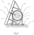
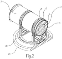
- the solar collector 1 shown in Figure 1 for the temporary storage of heat from solar radiation comprises a thermally-conducting core 2 within a cylindrical metal housing 3, as better shown in Figure 2 .
- the core 2 in this illustrative example is a solid block of steel that, in accordance with the present invention, can be heated to 1200 degrees Celsius.
- an insulated casing 4 is provided completely enveloping the core.
- the insulated casing 4 comprises a layer of ceramic material with a high insulation value.
- a first reflector body 5 which has one side reflecting radiation towards the core, to reflect back radiation escaping from the insulated casing back towards the core.
- the housing furthermore comprises means (not shown) of being able to create a vacuum within the housing, so that in spaces between the reflector bodies 5, 6 and the insulated casing 4 a virtually complete vacuum prevails. This virtually excludes a heat loss by convention or conduction.
- the outer side of the housing remains at a temperature when using the solar collector which virtually corresponds to that of an ambient temperature at a temperature of the core of 1200 degrees Celsius. So there is a negligent quantity of heat loss to the outside environment.
- the solar collector in accordance with the present invention thus provides a particularly thorough return, and is capable not only of providing energy during hours of sunshine, but also of creating an energy buffer from which, during periods of less solar radiation, continuous energy can be extracted.
- a screen 7 is placed in which lens means are provided to concentrate solar radiation.
- the lens means comprise a system of lenses placed at an equal distance apart and directed towards the sun, where in each case the solar radiation incident on the lens concentrates on its own focus. However, at the focus, behind each lens a first extremity of a radiation conductor in the form of a glass fibre is placed, so that the concentrated solar radiation is collected in the fibre. Through the glass fibres of each lens, the solar radiation is conducted towards the housing 3. For a maximum collection of solar radiation, tracking means are provided to be able to follow the passage of the sun over the day.
- the housing 3 is situated on a rotating first frame 20 that can be turned completely within a horizontal base 21 on which the solar collector is supported, while the screen with lenses is fastened to a rotating second frame 30 that rotates over a distance around the housing 3.
- a continuous adjustment of the lenses from one position to the next is realised by automatic driving of the rotating frames in response to a signal of the tracking means.
- the tracking means may comprise a sensor which continuously records the position of the sun and passes on to processing means such as a processor, for example, which processing means then sends an output signal to duly provided driving means which achieve a necessary adjustment of one of either frames 20, 30.
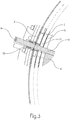
- an extremity of the glass fibre 8 is fastened by means of fastening means 10 to an outer side of the housing 3.
- the extremity of the glass fibre is thus received fitting onto an extremity of a quartz fibre 9, so that the solar radiation from the glass fibre transfers into the quartz fibre without loss of radiation.
- the quartz fibre 9 is fastened by means of further fastening means 11 to the inner side of the housing 3.
- Flexible adjustable means in the form of O-rings are provided in the leadthrough of the housing through which the radiation conductor extends to seal off the entirety.
- the quartz fibre 9 is guided from the inner side of the housing 3 to virtually up to the core 2 where the quartz fibre 9 forms the second extremity of the radiation conductor.
- the second extremity of the radiation conductor is fastened by means of fixing means 12 against the core 2 at the place of a recess in the core 2. Radiation particles released from the radiation conductor thus come into the space in the recess, so that the radiation can be incident at a greater core area and loss by reflection of radiation back to the radiation conductor is minimised.
Description
- The present invention relates to a solar collector for the temporary storage of heat from solar radiation according to the preamble of claim 1.
- Such a solar collector is known from the international patent application
WO 2009/002168 of the applicant. This known solar collector comprises a thermally-conducting core which can heat up from solar radiation and is capable of retaining this heat over a certain period. Unlike conventional solar collectors which heat a liquid by means of lens means to make use of it directly, this known solar collector makes it possible to generate usable energy even during periods in which the quantity of solar radiation received is relatively low, such as during the night. The thermally conducted core can, in fact, store a relatively large quantity of heat and is thus used as an energy buffer during such periods of low solar radiation. - Although the known solar collector can already be used effectively to generate energy continuously for longer periods, it is apparent that improvements can be made, in other words on the return, particularly by counteracting heat loss.
- The purpose of the present invention is thus to create a further improved solar collector of the type mentioned above.
- In order to achieve the intended aim, a solar collector is defined by the features of claim 1. The core is provided with an insulated casing virtually entirely enveloping the core, which insulated casing comprises a layer of porous ceramic material. The invention is based on the understanding that, in spite of the inherent insulation problem, a core with as high as possible a thermal capacity leads to the best results. Due to the high temperatures which can be achieved with a core with a high thermal capacity, it is highly significant that the insulation used is resistant to such temperatures. A layer of porous ceramic material is particularly well-suited as insulation to provide no or hardly any heat loss even at the highest temperatures. To counteract a leakage of heat as much as possible, the layer is provided in an insulated casing that virtually completely envelops the core anyway. Although such an insulated casing with ceramic material is not particularly lightweight, it is apparent that in particular with regard to the scale of relatively large solar collectors it is less inconvenient than expected. The energy loss by controlling the solar collector with increased weight does not affect the return by such a good insulation of a core with high thermal capacity.
- Given that every gap or weak point in the insulation layer increases the risk of a heat leakage, the solar collector in accordance with the invention in a preferential embodiment is characterised by the layer of ceramic material being virtually seamless. In this way, the layer of ceramic material can be moulded around the core in accordance with a further preferential embodiment of the solar collector in accordance with the present invention. Such moulding of the layer of ceramic material leads to a virtually uninterrupted integral body without seams, that has a virtually uniform insulation value over the entire surface. This prevents weak spots in the insulation as far as possible.
- To capture thermal radiation well, the layer of ceramic material is porous. For example, this can be done by taking a porous material or, for example, by adding a supplementary substance to the ceramic material that is burnt away from the layer when heating to leave behind a desired network of pores in the layer.
- In a further preferential embodiment, the solar collector in accordance with the invention is characterised in that the layer of ceramic material comprises a light flame-resistant masonry product. Such a masonry product, such as refractory materials, is to be applied simply in a desired form in a layer around the core, is resistant to very high temperatures and has outstanding insulation values.
- In a particular embodiment, the solar collector in accordance with the invention is characterised in that around one of the side of the insulated casing away from the core is provided with at least one reflector body with a radiation-reflecting side pointing towards the core. The reflector body shall only reflect the infrared radiation escaping through the insulated casing back to the core, which results in a further improvement of the insulation value of the whole.
- A further preferred embodiment of the solar collector in accordance with the invention is characterised in that the core and insulated casing are accommodated in a virtually air-tight closed housing and that means are provided for creating a virtual vacuum within the housing around the core and insulated casing. By creating a vacuum in the solar collector in all the spaces between the parts, a possible release of heat by conduction or convection heat transfer is limited as much as possible. In so doing, the thermal loss is virtually exclusively possible via radiation, which, however, due to the measures described above in accordance with the invention, is counteracted as much as possible.
- In a further preferred embodiment, the solar collector in accordance with the present invention is characterised in that the core comprises a heat-resistant, conductive material with a relatively high thermal capacity. A further particular embodiment of the solar collector in accordance with the present invention has the characteristic that the core comprises a solid block of steel. Steel has a suitable thermal capacity for use in the solar collector, and has a high melting point so that it can be used as a solid block in spite of the high temperature accumulating in the core. By using such a steel core, it is possible to heat the core to a temperature of 1500 degrees Celsius. The solar collector in accordance with the present invention thus has a further particular embodiment, however, as a characteristic that the core stores a temperature up to a maximum of 1200 degrees Celsius. Such a temperature of the core provides a sufficiently long energy buffer to bridge periods of less or no solar radiation, while all the components of the solar collector such as the radiation conductor appear to be resistant to this temperature.
- A further particular embodiment of the solar collector in accordance with the present invention has the characteristic that the core comprises a liquid mass of aluminium. Aluminium has an excellent thermal capacity, is relatively lightweight and is also very conductive, so that the heat can be extracted from it very quickly to generate energy from it. Due to the relatively low melting point of aluminium, a liquid mass of aluminium is necessary to achieve efficient temperatures in the core.
- According to the invention, the light conductor partly comprises quartz fibre. Such a quartz fibre is particularly suitable for conducting solar radiation over the length of the fibre without any significant loss of light. In particular, the quartz fibre is good at withstanding high temperatures achieved in the core of the solar collector, up to 1200 degrees Celsius. In this way, the quartz fibre is suitable for use close to the core of the solar collector.
- Although it is possible to manufacture a radiation conductor completely from quartz fibre, the use of glass fibre also provides advantages. Glass fibre is clearly less expensive compared with quartz fibre and, furthermore, is much more flexible. As a result, glass fibre is better suited for use in a radiation conductor with bends and curves. However, at higher temperatures, such as those which may occur in the core of the solar collector, the glass fibre is affected so that the radiation conduction is no longer optimum as a result. For this reason, according to the invention, the quartz fibre comprises the second extremity of the radiation conductor and extends to outside the insulated casing. Furthermore, the radiation conductor comprises a glass fibre. The glass fibre is bonded with the quartz fibre and comprises the first extremity of the radiation conductor. Only that part of the radiation conductor that must withstand the highest temperatures, in particular the part between the core and the insulated casing, is manufactured from heat-resistant quartz fibre, while the other part of the radiation conductor from the insulated casing until close to a focus of the lens means is made of more flexible glass fibre.
- A further preferential embodiment of the solar collector in accordance with the invention is characterised in that the radiation conductor is fastened with the second extremity to an outer side of the core at the location of a recess in the core and under the inclusion of a space in the recess to allow solar radiation emitting from the radiation conductor being converted into energy to come into contact with the surface of the core. The recess in the core creates a larger core area within the recess, by which the solar radiation being emitted from the radiation conductor is incident to remove the radiation energy in the form of heat to the core. In a further preferred embodiment, the solar collector in accordance with the present invention is characterised in that an anti-reflection coating against the core is applied into the recess. The anti-reflection coating absorbs the solar radiation emitted from the radiation conductor and emits this as heat to the core. In this way, the solar radiation being able to be reflected back into the radiation conductor, which would mean a loss of energy, is counteracted.
- The invention will now be explained in more detail using an illustrative example and associated drawing. In the drawing:
- Figure 1
- shows an illustrative example of a solar collector in accordance with the invention in a side elevation of a cross section;
- Figure 2
- shows a perspective view of the core in a housing of the illustrative example of a solar collector in accordance with the invention as shown in
Figure 1 ; - Figure 3
- shows a cross-section detailed view of the core in a housing in accordance with the region B as shown in
Figure 1 . - Incidentally, the figures are purely schematic and not drawn to scale. In fact, some of the dimensions are shown exaggerated for the sake of clarity.
- Corresponding parts are indicated with the same reference number in the figures where at all possible.
- The solar collector 1 shown in
Figure 1 for the temporary storage of heat from solar radiation comprises a thermally-conductingcore 2 within acylindrical metal housing 3, as better shown inFigure 2 . Thecore 2 in this illustrative example is a solid block of steel that, in accordance with the present invention, can be heated to 1200 degrees Celsius. To retain this heat for longer periods, around thecore 2 aninsulated casing 4 is provided completely enveloping the core. Theinsulated casing 4 comprises a layer of ceramic material with a high insulation value. At a distance from theinsulated casing 4 is provided afirst reflector body 5 which has one side reflecting radiation towards the core, to reflect back radiation escaping from the insulated casing back towards the core. At a distance from thefirst reflector body 5 is provided asecond reflector body 6 for a further reflection of radiation back to the core. The housing furthermore comprises means (not shown) of being able to create a vacuum within the housing, so that in spaces between thereflector bodies - The outer side of the housing remains at a temperature when using the solar collector which virtually corresponds to that of an ambient temperature at a temperature of the core of 1200 degrees Celsius. So there is a negligent quantity of heat loss to the outside environment. The solar collector in accordance with the present invention, thus provides a particularly thorough return, and is capable not only of providing energy during hours of sunshine, but also of creating an energy buffer from which, during periods of less solar radiation, continuous energy can be extracted.
- For heating of the
core 2, in front of the housing 3 a screen 7 is placed in which lens means are provided to concentrate solar radiation. The lens means comprise a system of lenses placed at an equal distance apart and directed towards the sun, where in each case the solar radiation incident on the lens concentrates on its own focus. However, at the focus, behind each lens a first extremity of a radiation conductor in the form of a glass fibre is placed, so that the concentrated solar radiation is collected in the fibre. Through the glass fibres of each lens, the solar radiation is conducted towards thehousing 3. For a maximum collection of solar radiation, tracking means are provided to be able to follow the passage of the sun over the day. For this purpose, thehousing 3 is situated on a rotatingfirst frame 20 that can be turned completely within ahorizontal base 21 on which the solar collector is supported, while the screen with lenses is fastened to a rotatingsecond frame 30 that rotates over a distance around thehousing 3. A continuous adjustment of the lenses from one position to the next is realised by automatic driving of the rotating frames in response to a signal of the tracking means. It will be apparent to a person skilled in the art that the tracking means, for example, may comprise a sensor which continuously records the position of the sun and passes on to processing means such as a processor, for example, which processing means then sends an output signal to duly provided driving means which achieve a necessary adjustment of one of eitherframes - As shown in
Figure 3 in more detail, an extremity of theglass fibre 8 is fastened by means of fastening means 10 to an outer side of thehousing 3. The extremity of the glass fibre is thus received fitting onto an extremity of aquartz fibre 9, so that the solar radiation from the glass fibre transfers into the quartz fibre without loss of radiation. Thequartz fibre 9 is fastened by means of further fastening means 11 to the inner side of thehousing 3. Flexible adjustable means in the form of O-rings are provided in the leadthrough of the housing through which the radiation conductor extends to seal off the entirety. Thequartz fibre 9 is guided from the inner side of thehousing 3 to virtually up to thecore 2 where thequartz fibre 9 forms the second extremity of the radiation conductor. The second extremity of the radiation conductor is fastened by means of fixing means 12 against thecore 2 at the place of a recess in thecore 2. Radiation particles released from the radiation conductor thus come into the space in the recess, so that the radiation can be incident at a greater core area and loss by reflection of radiation back to the radiation conductor is minimised. - Although the invention is further explained by means of merely a single illustrative example, it may be clear that the invention is no way restricted to it. On the contrary, many more variations and embodiments are possible to an average person skilled in the art within the framework of the invention.
Claims (10)
- Solar collector (1) for the temporary storage of heat from solar radiation comprising a radiation conductor for conducting solar radiation, lens means for concentrating solar radiation onto a first extremity of the radiation conductor, and comprising a thermally conducting core (2) on an opposite second extremity of the radiation conductor which core (2) is heated by the solar radiation emitted from the radiation conductor and is in a position to store the heat temporarily, wherein the core (2) is provided within an insulated casing (4) virtually completely enveloping the core (2), characterised in that the insulated casing (4) comprises a layer of porous ceramic material, wherein the radiation conductor comprises partly a quartz fibre (9), and wherein the quartz fibre (9) comprises the second extremity of the radiation conductor and extends to outside the insulated casing (4) wherein the radiation conductor further comprises a glass fibre, wherein the glass fibre (8) is connected to the quartz fibre (9) and comprises the first extremity of the radiation conductor.
- Solar collector in accordance with Claim 1, characterised in that the layer of ceramic material comprises a light fire-resistant layer of masonry.
- Solar collector in accordance with any one of Claims 1 to 2, characterised in that the layer of ceramic material is virtually seamless, in particular is moulded around the core (2).
- Solar collector in accordance with any one or more of the preceding claims, characterised in that around the insulated casing (4) on the side away from the core (2), at least one reflector body (5) is provided with a reflective side pointing towards the core (2).
- Solar collector in accordance with any one or more of the preceding claims, characterised in that the core (2) and insulated casing (4) are accommodated in a housing (3) enclosed virtually air-tight and that means are provided for virtually creating a vacuum within the housing (3) around the core (2) and insulated casing (4).
- Solar collector in accordance with one or more of the preceding claims, characterised in that the core (2) comprises a heat-resistant, conductive material, particularly a metal.
- Solar collector in accordance with Claim 6, characterised that the core (2) comprises a solid block of steel.
- Solar collector in accordance with Claim 6, characterised in that the core (2) comprises a liquid mass of aluminium.
- Solar collector in accordance with any one or more of the preceding claims, characterised in that the core (2) stores a temperature up to maximum 1200 degrees Celsius.
- Solar collector in accordance with any one or more of the preceding claims, characterised in that the radiation conductor is fastened with the second extremity to an outside side of the core (2) at the location of a recess in the core (2) and under the inclusion of a space in the recess to allow the solar radiation from the radiation conductor changing into energy to come into contact with a surface of the core (2).
Priority Applications (6)
| Application Number | Priority Date | Filing Date | Title |
|---|---|---|---|
| SI201431502T SI3234476T1 (en) | 2013-12-23 | 2014-12-19 | Solar collector |
| RS20200179A RS60046B1 (en) | 2013-12-23 | 2014-12-19 | Solar collector |
| PL14833266T PL3234476T3 (en) | 2013-12-23 | 2014-12-19 | Solar collector |
| PT148332661T PT3234476T (en) | 2013-12-23 | 2014-12-19 | Solar collector |
| HUE14833266A HUE048425T2 (en) | 2013-12-23 | 2014-12-19 | Solar collector |
| HRP20200277TT HRP20200277T1 (en) | 2013-12-23 | 2020-02-18 | Solar collector |
Applications Claiming Priority (2)
| Application Number | Priority Date | Filing Date | Title |
|---|---|---|---|
| NL2012014A NL2012014C2 (en) | 2013-12-23 | 2013-12-23 | SUN COLLECTOR. |
| PCT/IB2014/067159 WO2015097629A1 (en) | 2013-12-23 | 2014-12-19 | Solar collector |
Publications (2)
| Publication Number | Publication Date |
|---|---|
| EP3234476A1 EP3234476A1 (en) | 2017-10-25 |
| EP3234476B1 true EP3234476B1 (en) | 2019-11-20 |
Family
ID=52434899
Family Applications (1)
| Application Number | Title | Priority Date | Filing Date |
|---|---|---|---|
| EP14833266.1A Active EP3234476B1 (en) | 2013-12-23 | 2014-12-19 | Solar collector |
Country Status (22)
| Country | Link |
|---|---|
| US (1) | US10408498B2 (en) |
| EP (1) | EP3234476B1 (en) |
| JP (1) | JP6648154B2 (en) |
| CN (2) | CN107003032A (en) |
| AU (1) | AU2014372174B2 (en) |
| BR (1) | BR112017012070B8 (en) |
| CA (1) | CA2969497C (en) |
| CY (1) | CY1122752T1 (en) |
| DK (1) | DK3234476T3 (en) |
| ES (1) | ES2773267T3 (en) |
| HR (1) | HRP20200277T1 (en) |
| HU (1) | HUE048425T2 (en) |
| LT (1) | LT3234476T (en) |
| MA (1) | MA40654B1 (en) |
| MX (1) | MX2017007526A (en) |
| NL (1) | NL2012014C2 (en) |
| PL (1) | PL3234476T3 (en) |
| PT (1) | PT3234476T (en) |
| RS (1) | RS60046B1 (en) |
| RU (1) | RU2670638C9 (en) |
| SI (1) | SI3234476T1 (en) |
| WO (1) | WO2015097629A1 (en) |
Families Citing this family (12)
| Publication number | Priority date | Publication date | Assignee | Title |
|---|---|---|---|---|
| USD783521S1 (en) * | 2014-12-19 | 2017-04-11 | Jln Solar, Inc. | Solar panel mount |
| CN106108647A (en) * | 2016-06-07 | 2016-11-16 | 宁波高新区世代能源科技有限公司 | Solar energy water-boiling water dispenser |
| NO346227B1 (en) * | 2019-11-07 | 2022-05-02 | Andric Milos | Concentrated solar power system |
| NL2024827B1 (en) | 2020-02-04 | 2021-09-13 | Jacobus Maria Schilder Johannes | Energy transfer apparatus and associated methods |
| NL2024830B1 (en) | 2020-02-04 | 2021-09-13 | Jacobus Maria Schilder Johannes | Energy transfer apparatus and associated methods |
| NL2024831B1 (en) | 2020-02-04 | 2021-09-13 | Jacobus Maria Schilder Johannes | Energy transfer apparatus and associated methods |
| NL2024832B1 (en) | 2020-02-04 | 2021-09-13 | Jacobus Maria Schilder Johannes | Energy transfer apparatus and associated methods |
| NL2024829B1 (en) | 2020-02-04 | 2021-09-13 | Jacobus Maria Schilder Johannes | Energy transfer apparatus and associated methods |
| NL2024833B1 (en) | 2020-02-04 | 2021-09-13 | Jacobus Maria Schilder Johannes | Energy transfer apparatus and associated methods |
| BR112022013518A2 (en) | 2020-02-04 | 2022-09-13 | Jacobus Maria Schilder Johannes | ENERGY TRANSFER APPARATUS AND ASSOCIATED METHODS |
| CN112833566A (en) * | 2021-01-22 | 2021-05-25 | 赣州能创智能科技有限公司 | High-efficiency vacuum heat pipe collector |
| CN112833565A (en) * | 2021-01-22 | 2021-05-25 | 赣州能创智能科技有限公司 | Efficient heat collection method of vacuum heat pipe |
Family Cites Families (29)
| Publication number | Priority date | Publication date | Assignee | Title |
|---|---|---|---|---|
| DE2517898A1 (en) * | 1975-04-23 | 1976-11-04 | Eduard Prof Dr Techn Justi | LOW-LOSS SOLAR HEAT COLLECTORS |
| US4018212A (en) * | 1976-02-13 | 1977-04-19 | Hein Leopold A | Solar heating and cooking apparatus |
| US4316048A (en) * | 1980-06-20 | 1982-02-16 | International Business Machines Corporation | Energy conversion |
| JPS5716758A (en) * | 1980-07-03 | 1982-01-28 | Matsushita Electric Ind Co Ltd | Accumulating device for solar energy |
| DE3139104A1 (en) * | 1981-08-21 | 1983-03-10 | M.A.N. Maschinenfabrik Augsburg-Nürnberg AG, 8000 München | Method of producing a high-temperature insulation |
| US4511755A (en) * | 1982-05-17 | 1985-04-16 | Kei Mori | Solar ray collection apparatus |
| SU1247631A1 (en) * | 1983-07-13 | 1986-07-30 | Polyakovskij Lev Yu | Solar heat unit |
| JPH0727425A (en) * | 1991-02-25 | 1995-01-27 | Showa Device Plant Kk | Solar concentrator and thermal storage apparatus |
| SU1815527A1 (en) * | 1991-03-13 | 1993-05-15 | Dagestanskij Inzh Ts Sp Str Ob | High-temperature solar collector |
| US5191875A (en) | 1991-09-27 | 1993-03-09 | Edling Jack V | High efficiency solar boiler |
| US5761356A (en) * | 1996-08-19 | 1998-06-02 | Cogent Light Technologies, Inc. | Apparatus and method for coupling high intensity light into low temperature optical fiber |
| DE19713598C2 (en) * | 1997-04-02 | 2000-05-25 | Deutsch Zentr Luft & Raumfahrt | Insulation system |
| CH690079A5 (en) * | 1998-09-17 | 2000-04-14 | Alois Zeder | Heat storage. |
| RU2191328C1 (en) * | 2001-02-27 | 2002-10-20 | Орловский государственный технический университет | Solar heating panel for buildings |
| JP2004332672A (en) * | 2003-05-12 | 2004-11-25 | Taiyoko Kenkyusho:Kk | Stirling engine power-generating device using solar light and heat |
| DE10335425B3 (en) * | 2003-08-01 | 2004-08-26 | Öko-Insel Energietechnik GmbH | Heat storage unit, for storing heat, comprises base body made from ceramic materials for storing heat and having heat-conducting insert surrounded by protective layer |
| CN2699191Y (en) * | 2004-03-01 | 2005-05-11 | 谭显教 | Solar energy collecting, transmitting and storage device |
| US20070221208A1 (en) * | 2006-03-07 | 2007-09-27 | Goldman Arnold J | High-temperature pipeline |
| NL1034015C2 (en) | 2007-06-22 | 2008-12-23 | Schilder Johannes Jacobus Mari | Solar collector with lens means. |
| KR100920796B1 (en) * | 2007-08-30 | 2009-10-08 | 조극래 | Thermal storage unit using electron wave of solar radiation |
| CN102165269B (en) * | 2008-09-25 | 2014-03-12 | 索尔法斯特私人有限公司 | Solar collector |
| CN101592309B (en) * | 2009-03-31 | 2011-07-13 | 上海友度科贸有限公司 | Sunlight lead-in daylighting device |
| SI2302308T1 (en) * | 2009-06-10 | 2016-10-28 | Knauf Insulation | Colored mineral wool |
| EP2278249A1 (en) * | 2009-07-24 | 2011-01-26 | JB Group ApS | Heat storage system |
| GB2486210A (en) * | 2010-12-06 | 2012-06-13 | Alstom Technology Ltd | Solar receiver comprising an aperture admitting radiation into a cylindrical cavity |
| JP2013119969A (en) * | 2011-12-06 | 2013-06-17 | Mitsubishi Heavy Ind Ltd | Solar thermal receiver and solar thermal electric generation system |
| DE102012000209A1 (en) * | 2012-01-03 | 2013-07-04 | Schubs GmbH | METHOD AND DEVICE FOR EFFICIENT STORAGE OF SOLAR ENERGY |
| CN102861907A (en) * | 2012-09-05 | 2013-01-09 | 广州立中锦山合金有限公司 | Heat accumulation type molten aluminum or aluminum alloy liquid storage and transportation device |
| CN103231869B (en) * | 2013-05-14 | 2015-04-08 | 常州循天节能科技有限公司 | Thermal insulation structure of thermal medium storage tank and thermal medium pipe of solar photo-thermal power generation system |
-
2013
- 2013-12-23 NL NL2012014A patent/NL2012014C2/en active
-
2014
- 2014-12-19 CN CN201480084010.6A patent/CN107003032A/en active Pending
- 2014-12-19 RU RU2017120212A patent/RU2670638C9/en active
- 2014-12-19 SI SI201431502T patent/SI3234476T1/en unknown
- 2014-12-19 MX MX2017007526A patent/MX2017007526A/en unknown
- 2014-12-19 MA MA40654A patent/MA40654B1/en unknown
- 2014-12-19 PT PT148332661T patent/PT3234476T/en unknown
- 2014-12-19 CA CA2969497A patent/CA2969497C/en active Active
- 2014-12-19 CN CN202111396353.4A patent/CN114294842A/en active Pending
- 2014-12-19 JP JP2017549859A patent/JP6648154B2/en active Active
- 2014-12-19 HU HUE14833266A patent/HUE048425T2/en unknown
- 2014-12-19 BR BR112017012070A patent/BR112017012070B8/en active IP Right Grant
- 2014-12-19 AU AU2014372174A patent/AU2014372174B2/en active Active
- 2014-12-19 RS RS20200179A patent/RS60046B1/en unknown
- 2014-12-19 ES ES14833266T patent/ES2773267T3/en active Active
- 2014-12-19 WO PCT/IB2014/067159 patent/WO2015097629A1/en active Application Filing
- 2014-12-19 LT LTEP14833266.1T patent/LT3234476T/en unknown
- 2014-12-19 DK DK14833266.1T patent/DK3234476T3/en active
- 2014-12-19 PL PL14833266T patent/PL3234476T3/en unknown
- 2014-12-19 US US15/534,430 patent/US10408498B2/en active Active
- 2014-12-19 EP EP14833266.1A patent/EP3234476B1/en active Active
-
2020
- 2020-02-18 HR HRP20200277TT patent/HRP20200277T1/en unknown
- 2020-02-19 CY CY20201100152T patent/CY1122752T1/en unknown
Non-Patent Citations (1)
| Title |
|---|
| None * |
Also Published As
| Publication number | Publication date |
|---|---|
| HUE048425T2 (en) | 2020-07-28 |
| BR112017012070A2 (en) | 2017-12-26 |
| AU2014372174B2 (en) | 2019-11-21 |
| WO2015097629A1 (en) | 2015-07-02 |
| RU2670638C1 (en) | 2018-10-24 |
| NL2012014C2 (en) | 2015-06-26 |
| CN114294842A (en) | 2022-04-08 |
| CA2969497A1 (en) | 2015-07-02 |
| MX2017007526A (en) | 2018-08-15 |
| BR112017012070B8 (en) | 2022-09-06 |
| BR112017012070B1 (en) | 2021-12-14 |
| RU2670638C9 (en) | 2018-12-04 |
| MA40654B1 (en) | 2019-06-28 |
| PT3234476T (en) | 2020-02-28 |
| CY1122752T1 (en) | 2021-03-12 |
| JP6648154B2 (en) | 2020-02-14 |
| CA2969497C (en) | 2020-03-10 |
| JP2018503056A (en) | 2018-02-01 |
| SI3234476T1 (en) | 2020-04-30 |
| US10408498B2 (en) | 2019-09-10 |
| DK3234476T3 (en) | 2020-03-02 |
| EP3234476A1 (en) | 2017-10-25 |
| RS60046B1 (en) | 2020-04-30 |
| HRP20200277T1 (en) | 2020-09-04 |
| PL3234476T3 (en) | 2020-05-18 |
| MA40654A1 (en) | 2018-03-30 |
| NZ732365A (en) | 2021-09-24 |
| US20170343242A1 (en) | 2017-11-30 |
| CN107003032A (en) | 2017-08-01 |
| ES2773267T3 (en) | 2020-07-10 |
| LT3234476T (en) | 2020-03-10 |
| AU2014372174A1 (en) | 2017-06-22 |
Similar Documents
| Publication | Publication Date | Title |
|---|---|---|
| EP3234476B1 (en) | Solar collector | |
| US8430093B1 (en) | Solar collector using subreflector | |
| US2888007A (en) | Windows for admitting solar radiation | |
| EP2491599A2 (en) | Window | |
| WO2013151601A2 (en) | Cavity receivers for parabolic solar troughs | |
| EP2192360A1 (en) | A reflector and a solar tank-type heat collector applying it | |
| EP3111146A1 (en) | Advanced cavity receivers for parabolic solar troughs | |
| WO2012073664A1 (en) | Solar thermal collector tube | |
| EP2908069B1 (en) | Solar thermal absorber element | |
| Zhao et al. | A spectrally selective surface structure for combined photothermic conversion and radiative sky cooling | |
| NZ733534A (en) | System for controlling a service station related to a vehicle | |
| NZ733534B2 (en) | Antenna for identification tag and identification tag with antenna | |
| EP2923157B1 (en) | Solar receiver for fresnel concentrated solar power plant including a frame made of an insulating material and method for manufacturing same | |
| KR20140118451A (en) | Solar energy collecting vacuum panel and solar energy collecting module using the same | |
| CN101377356A (en) | Cavity absorption type solar glass vacuum thermal-collecting tube | |
| RU90884U1 (en) | SOLAR COLLECTOR | |
| JP5705517B2 (en) | Solar collector tube | |
| CN102834580A (en) | Solar collector | |
| JPS6030948A (en) | Solar heat collecting device | |
| EP2802826A1 (en) | Radiation based overheat prevention mechanism for solar thermal collectors | |
| IT201900019996A1 (en) | Solar receiver for heating fluids directly | |
| ITMI20070753A1 (en) | SOLAR CONCENTRATOR |
Legal Events
| Date | Code | Title | Description |
|---|---|---|---|
| PUAI | Public reference made under article 153(3) epc to a published international application that has entered the european phase |
Free format text: ORIGINAL CODE: 0009012 |
|
| 17P | Request for examination filed |
Effective date: 20170609 |
|
| AK | Designated contracting states |
Kind code of ref document: A1 Designated state(s): AL AT BE BG CH CY CZ DE DK EE ES FI FR GB GR HR HU IE IS IT LI LT LU LV MC MK MT NL NO PL PT RO RS SE SI SK SM TR |
|
| AX | Request for extension of the european patent |
Extension state: BA ME |
|
| DAX | Request for extension of the european patent (deleted) | ||
| REG | Reference to a national code |
Ref country code: DE Ref legal event code: R079 Ref document number: 602014057237 Country of ref document: DE Free format text: PREVIOUS MAIN CLASS: F24J0002060000 Ipc: F24S0023000000 |
|
| GRAP | Despatch of communication of intention to grant a patent |
Free format text: ORIGINAL CODE: EPIDOSNIGR1 |
|
| RIC1 | Information provided on ipc code assigned before grant |
Ipc: F24S 23/00 20180101AFI20190606BHEP Ipc: F24S 30/452 20180101ALI20190606BHEP Ipc: F24S 60/00 20180101ALI20190606BHEP Ipc: F24S 80/60 20180101ALI20190606BHEP Ipc: F24S 23/30 20180101ALI20190606BHEP Ipc: F24S 80/65 20180101ALI20190606BHEP |
|
| INTG | Intention to grant announced |
Effective date: 20190626 |
|
| GRAS | Grant fee paid |
Free format text: ORIGINAL CODE: EPIDOSNIGR3 |
|
| GRAA | (expected) grant |
Free format text: ORIGINAL CODE: 0009210 |
|
| AK | Designated contracting states |
Kind code of ref document: B1 Designated state(s): AL AT BE BG CH CY CZ DE DK EE ES FI FR GB GR HR HU IE IS IT LI LT LU LV MC MK MT NL NO PL PT RO RS SE SI SK SM TR |
|
| REG | Reference to a national code |
Ref country code: GB Ref legal event code: FG4D |
|
| REG | Reference to a national code |
Ref country code: CH Ref legal event code: EP |
|
| REG | Reference to a national code |
Ref country code: IE Ref legal event code: FG4D |
|
| REG | Reference to a national code |
Ref country code: AT Ref legal event code: REF Ref document number: 1204634 Country of ref document: AT Kind code of ref document: T Effective date: 20191215 |
|
| REG | Reference to a national code |
Ref country code: DE Ref legal event code: R096 Ref document number: 602014057237 Country of ref document: DE |
|
| REG | Reference to a national code |
Ref country code: HR Ref legal event code: TUEP Ref document number: P20200277T Country of ref document: HR |
|
| REG | Reference to a national code |
Ref country code: RO Ref legal event code: EPE |
|
| REG | Reference to a national code |
Ref country code: FI Ref legal event code: FGE |
|
| REG | Reference to a national code |
Ref country code: PT Ref legal event code: SC4A Ref document number: 3234476 Country of ref document: PT Date of ref document: 20200228 Kind code of ref document: T Free format text: AVAILABILITY OF NATIONAL TRANSLATION Effective date: 20200218 Ref country code: CH Ref legal event code: NV Representative=s name: TR-IP CONSULTING LLC, CH |
|
| REG | Reference to a national code |
Ref country code: DK Ref legal event code: T3 Effective date: 20200225 |
|
| REG | Reference to a national code |
Ref country code: SE Ref legal event code: TRGR |
|
| REG | Reference to a national code |
Ref country code: NL Ref legal event code: FP |
|
| REG | Reference to a national code |
Ref country code: NO Ref legal event code: T2 Effective date: 20191120 |
|
| PGFP | Annual fee paid to national office [announced via postgrant information from national office to epo] |
Ref country code: LV Payment date: 20200218 Year of fee payment: 6 Ref country code: LT Payment date: 20200219 Year of fee payment: 6 Ref country code: MC Payment date: 20200218 Year of fee payment: 6 |
|
| REG | Reference to a national code |
Ref country code: SK Ref legal event code: T3 Ref document number: E 33554 Country of ref document: SK |
|
| REG | Reference to a national code |
Ref country code: HR Ref legal event code: ODRP Ref document number: P20200277T Country of ref document: HR Payment date: 20200221 Year of fee payment: 6 Ref country code: EE Ref legal event code: FG4A Ref document number: E018844 Country of ref document: EE Effective date: 20200218 |
|
| REG | Reference to a national code |
Ref country code: GR Ref legal event code: EP Ref document number: 20200400451 Country of ref document: GR Effective date: 20200511 |
|
| PGFP | Annual fee paid to national office [announced via postgrant information from national office to epo] |
Ref country code: RS Payment date: 20200218 Year of fee payment: 6 Ref country code: IS Payment date: 20200219 Year of fee payment: 6 Ref country code: LU Payment date: 20200217 Year of fee payment: 6 Ref country code: SM Payment date: 20200220 Year of fee payment: 6 Ref country code: SI Payment date: 20200217 Year of fee payment: 6 |
|
| PG25 | Lapsed in a contracting state [announced via postgrant information from national office to epo] |
Ref country code: AL Free format text: LAPSE BECAUSE OF FAILURE TO SUBMIT A TRANSLATION OF THE DESCRIPTION OR TO PAY THE FEE WITHIN THE PRESCRIBED TIME-LIMIT Effective date: 20191120 |
|
| PGFP | Annual fee paid to national office [announced via postgrant information from national office to epo] |
Ref country code: MT Payment date: 20200217 Year of fee payment: 6 |
|
| REG | Reference to a national code |
Ref country code: ES Ref legal event code: FG2A Ref document number: 2773267 Country of ref document: ES Kind code of ref document: T3 Effective date: 20200710 |
|
| REG | Reference to a national code |
Ref country code: HU Ref legal event code: AG4A Ref document number: E048425 Country of ref document: HU |
|
| PGFP | Annual fee paid to national office [announced via postgrant information from national office to epo] |
Ref country code: CY Payment date: 20200226 Year of fee payment: 6 Ref country code: EE Payment date: 20200218 Year of fee payment: 6 |
|
| REG | Reference to a national code |
Ref country code: DE Ref legal event code: R097 Ref document number: 602014057237 Country of ref document: DE |
|
| PGFP | Annual fee paid to national office [announced via postgrant information from national office to epo] |
Ref country code: SK Payment date: 20200217 Year of fee payment: 6 |
|
| REG | Reference to a national code |
Ref country code: HR Ref legal event code: T1PR Ref document number: P20200277 Country of ref document: HR |
|
| PLBE | No opposition filed within time limit |
Free format text: ORIGINAL CODE: 0009261 |
|
| STAA | Information on the status of an ep patent application or granted ep patent |
Free format text: STATUS: NO OPPOSITION FILED WITHIN TIME LIMIT |
|
| 26N | No opposition filed |
Effective date: 20200821 |
|
| REG | Reference to a national code |
Ref country code: HR Ref legal event code: ODRP Ref document number: P20200277 Country of ref document: HR Payment date: 20201216 Year of fee payment: 7 |
|
| REG | Reference to a national code |
Ref country code: EE Ref legal event code: MM4A Ref document number: E018844 Country of ref document: EE Effective date: 20201231 |
|
| PG25 | Lapsed in a contracting state [announced via postgrant information from national office to epo] |
Ref country code: CY Free format text: LAPSE BECAUSE OF NON-PAYMENT OF DUE FEES Effective date: 20201219 |
|
| REG | Reference to a national code |
Ref country code: SK Ref legal event code: MM4A Ref document number: E 33554 Country of ref document: SK Effective date: 20201219 |
|
| PG25 | Lapsed in a contracting state [announced via postgrant information from national office to epo] |
Ref country code: MC Free format text: LAPSE BECAUSE OF NON-PAYMENT OF DUE FEES Effective date: 20210104 |
|
| PG25 | Lapsed in a contracting state [announced via postgrant information from national office to epo] |
Ref country code: RS Free format text: LAPSE BECAUSE OF NON-PAYMENT OF DUE FEES Effective date: 20201219 |
|
| REG | Reference to a national code |
Ref country code: LT Ref legal event code: MM4D Effective date: 20201219 |
|
| PG25 | Lapsed in a contracting state [announced via postgrant information from national office to epo] |
Ref country code: EE Free format text: LAPSE BECAUSE OF NON-PAYMENT OF DUE FEES Effective date: 20201231 Ref country code: LU Free format text: LAPSE BECAUSE OF NON-PAYMENT OF DUE FEES Effective date: 20201219 Ref country code: SM Free format text: LAPSE BECAUSE OF NON-PAYMENT OF DUE FEES Effective date: 20210707 |
|
| PG25 | Lapsed in a contracting state [announced via postgrant information from national office to epo] |
Ref country code: SK Free format text: LAPSE BECAUSE OF NON-PAYMENT OF DUE FEES Effective date: 20201219 |
|
| REG | Reference to a national code |
Ref country code: HR Ref legal event code: ODRP Ref document number: P20200277 Country of ref document: HR Payment date: 20211119 Year of fee payment: 8 |
|
| REG | Reference to a national code |
Ref country code: AT Ref legal event code: UEP Ref document number: 1204634 Country of ref document: AT Kind code of ref document: T Effective date: 20191120 |
|
| PG25 | Lapsed in a contracting state [announced via postgrant information from national office to epo] |
Ref country code: LT Free format text: LAPSE BECAUSE OF NON-PAYMENT OF DUE FEES Effective date: 20201219 |
|
| REG | Reference to a national code |
Ref country code: SI Ref legal event code: KO00 Effective date: 20211129 |
|
| PG25 | Lapsed in a contracting state [announced via postgrant information from national office to epo] |
Ref country code: SI Free format text: LAPSE BECAUSE OF NON-PAYMENT OF DUE FEES Effective date: 20201220 |
|
| PG25 | Lapsed in a contracting state [announced via postgrant information from national office to epo] |
Ref country code: MT Free format text: LAPSE BECAUSE OF NON-PAYMENT OF DUE FEES Effective date: 20201219 |
|
| PG25 | Lapsed in a contracting state [announced via postgrant information from national office to epo] |
Ref country code: LV Free format text: LAPSE BECAUSE OF NON-PAYMENT OF DUE FEES Effective date: 20201219 |
|
| REG | Reference to a national code |
Ref country code: HR Ref legal event code: ODRP Ref document number: P20200277 Country of ref document: HR Payment date: 20221208 Year of fee payment: 9 |
|
| PGFP | Annual fee paid to national office [announced via postgrant information from national office to epo] |
Ref country code: PL Payment date: 20221208 Year of fee payment: 9 Ref country code: HR Payment date: 20221208 Year of fee payment: 9 Ref country code: BE Payment date: 20221215 Year of fee payment: 9 |
|
| PGFP | Annual fee paid to national office [announced via postgrant information from national office to epo] |
Ref country code: ES Payment date: 20230111 Year of fee payment: 9 Ref country code: CH Payment date: 20230104 Year of fee payment: 9 |
|
| PG25 | Lapsed in a contracting state [announced via postgrant information from national office to epo] |
Ref country code: AL Free format text: LAPSE BECAUSE OF NON-PAYMENT OF DUE FEES Effective date: 20201219 |
|
| PGFP | Annual fee paid to national office [announced via postgrant information from national office to epo] |
Ref country code: GR Payment date: 20231204 Year of fee payment: 10 Ref country code: GB Payment date: 20231115 Year of fee payment: 10 |
|
| PGFP | Annual fee paid to national office [announced via postgrant information from national office to epo] |
Ref country code: TR Payment date: 20231120 Year of fee payment: 10 Ref country code: SE Payment date: 20231208 Year of fee payment: 10 Ref country code: RO Payment date: 20231121 Year of fee payment: 10 Ref country code: PT Payment date: 20231120 Year of fee payment: 10 Ref country code: NO Payment date: 20231211 Year of fee payment: 10 Ref country code: NL Payment date: 20231205 Year of fee payment: 10 Ref country code: IT Payment date: 20231204 Year of fee payment: 10 Ref country code: IE Payment date: 20231213 Year of fee payment: 10 Ref country code: HU Payment date: 20231123 Year of fee payment: 10 Ref country code: FR Payment date: 20231204 Year of fee payment: 10 Ref country code: FI Payment date: 20231201 Year of fee payment: 10 Ref country code: DK Payment date: 20231211 Year of fee payment: 10 Ref country code: DE Payment date: 20231208 Year of fee payment: 10 Ref country code: CZ Payment date: 20231120 Year of fee payment: 10 Ref country code: BG Payment date: 20231205 Year of fee payment: 10 Ref country code: AT Payment date: 20231204 Year of fee payment: 10 |
|
| PGFP | Annual fee paid to national office [announced via postgrant information from national office to epo] |
Ref country code: PL Payment date: 20231120 Year of fee payment: 10 Ref country code: BE Payment date: 20231212 Year of fee payment: 10 |
|
| PGFP | Annual fee paid to national office [announced via postgrant information from national office to epo] |
Ref country code: ES Payment date: 20240110 Year of fee payment: 10 |