EP3234436B1 - Systeme zum abdichten von kanalrohren mit einem gelmolch - Google Patents
Systeme zum abdichten von kanalrohren mit einem gelmolch Download PDFInfo
- Publication number
- EP3234436B1 EP3234436B1 EP15869459.6A EP15869459A EP3234436B1 EP 3234436 B1 EP3234436 B1 EP 3234436B1 EP 15869459 A EP15869459 A EP 15869459A EP 3234436 B1 EP3234436 B1 EP 3234436B1
- Authority
- EP
- European Patent Office
- Prior art keywords
- pig
- gel
- pipeline
- sealant composition
- train
- Prior art date
- Legal status (The legal status is an assumption and is not a legal conclusion. Google has not performed a legal analysis and makes no representation as to the accuracy of the status listed.)
- Active
Links
- 238000007789 sealing Methods 0.000 title description 26
- 239000000203 mixture Substances 0.000 claims description 105
- 239000000565 sealant Substances 0.000 claims description 52
- 239000012530 fluid Substances 0.000 claims description 38
- 241000282887 Suidae Species 0.000 claims description 34
- 239000004094 surface-active agent Substances 0.000 claims description 14
- 239000007788 liquid Substances 0.000 claims description 13
- WNROFYMDJYEPJX-UHFFFAOYSA-K aluminium hydroxide Chemical group [OH-].[OH-].[OH-].[Al+3] WNROFYMDJYEPJX-UHFFFAOYSA-K 0.000 claims description 9
- 239000002563 ionic surfactant Substances 0.000 claims description 7
- 230000002209 hydrophobic effect Effects 0.000 claims description 4
- 229910052500 inorganic mineral Inorganic materials 0.000 claims description 4
- 239000011707 mineral Substances 0.000 claims description 4
- ILRRQNADMUWWFW-UHFFFAOYSA-K aluminium phosphate Chemical compound O1[Al]2OP1(=O)O2 ILRRQNADMUWWFW-UHFFFAOYSA-K 0.000 claims description 3
- 239000001506 calcium phosphate Substances 0.000 claims description 3
- 229910000389 calcium phosphate Inorganic materials 0.000 claims description 3
- 235000011010 calcium phosphates Nutrition 0.000 claims description 3
- 239000002736 nonionic surfactant Substances 0.000 claims description 3
- QORWJWZARLRLPR-UHFFFAOYSA-H tricalcium bis(phosphate) Chemical compound [Ca+2].[Ca+2].[Ca+2].[O-]P([O-])([O-])=O.[O-]P([O-])([O-])=O QORWJWZARLRLPR-UHFFFAOYSA-H 0.000 claims description 3
- 239000000499 gel Substances 0.000 description 88
- XLYOFNOQVPJJNP-UHFFFAOYSA-N water Substances O XLYOFNOQVPJJNP-UHFFFAOYSA-N 0.000 description 27
- 238000000034 method Methods 0.000 description 21
- 239000003921 oil Substances 0.000 description 17
- 235000019198 oils Nutrition 0.000 description 16
- VYPSYNLAJGMNEJ-UHFFFAOYSA-N Silicium dioxide Chemical compound O=[Si]=O VYPSYNLAJGMNEJ-UHFFFAOYSA-N 0.000 description 14
- 239000000839 emulsion Substances 0.000 description 11
- 229920000642 polymer Polymers 0.000 description 10
- 238000004891 communication Methods 0.000 description 9
- VTYYLEPIZMXCLO-UHFFFAOYSA-L Calcium carbonate Chemical compound [Ca+2].[O-]C([O-])=O VTYYLEPIZMXCLO-UHFFFAOYSA-L 0.000 description 8
- 239000000463 material Substances 0.000 description 8
- 239000000945 filler Substances 0.000 description 7
- 239000000377 silicon dioxide Substances 0.000 description 7
- 229920000663 Hydroxyethyl cellulose Polymers 0.000 description 6
- 239000004354 Hydroxyethyl cellulose Substances 0.000 description 6
- OKKJLVBELUTLKV-UHFFFAOYSA-N Methanol Chemical compound OC OKKJLVBELUTLKV-UHFFFAOYSA-N 0.000 description 6
- 239000003795 chemical substances by application Substances 0.000 description 6
- 235000019447 hydroxyethyl cellulose Nutrition 0.000 description 6
- 229920001817 Agar Polymers 0.000 description 5
- OKTJSMMVPCPJKN-UHFFFAOYSA-N Carbon Chemical compound [C] OKTJSMMVPCPJKN-UHFFFAOYSA-N 0.000 description 5
- 239000004215 Carbon black (E152) Substances 0.000 description 5
- 229920002153 Hydroxypropyl cellulose Polymers 0.000 description 5
- 235000010419 agar Nutrition 0.000 description 5
- 230000015572 biosynthetic process Effects 0.000 description 5
- AXCZMVOFGPJBDE-UHFFFAOYSA-L calcium dihydroxide Chemical compound [OH-].[OH-].[Ca+2] AXCZMVOFGPJBDE-UHFFFAOYSA-L 0.000 description 5
- 239000000920 calcium hydroxide Substances 0.000 description 5
- 229910001861 calcium hydroxide Inorganic materials 0.000 description 5
- 235000010418 carrageenan Nutrition 0.000 description 5
- 239000000679 carrageenan Substances 0.000 description 5
- 229920001525 carrageenan Polymers 0.000 description 5
- 229940113118 carrageenan Drugs 0.000 description 5
- 229930195733 hydrocarbon Natural products 0.000 description 5
- 239000001863 hydroxypropyl cellulose Substances 0.000 description 5
- 235000010977 hydroxypropyl cellulose Nutrition 0.000 description 5
- VTHJTEIRLNZDEV-UHFFFAOYSA-L magnesium dihydroxide Chemical compound [OH-].[OH-].[Mg+2] VTHJTEIRLNZDEV-UHFFFAOYSA-L 0.000 description 5
- 239000000347 magnesium hydroxide Substances 0.000 description 5
- 229910001862 magnesium hydroxide Inorganic materials 0.000 description 5
- 239000003566 sealing material Substances 0.000 description 5
- 239000007787 solid Substances 0.000 description 5
- UHVMMEOXYDMDKI-JKYCWFKZSA-L zinc;1-(5-cyanopyridin-2-yl)-3-[(1s,2s)-2-(6-fluoro-2-hydroxy-3-propanoylphenyl)cyclopropyl]urea;diacetate Chemical compound [Zn+2].CC([O-])=O.CC([O-])=O.CCC(=O)C1=CC=C(F)C([C@H]2[C@H](C2)NC(=O)NC=2N=CC(=CC=2)C#N)=C1O UHVMMEOXYDMDKI-JKYCWFKZSA-L 0.000 description 5
- 241000206672 Gelidium Species 0.000 description 4
- 239000003945 anionic surfactant Substances 0.000 description 4
- 239000002585 base Substances 0.000 description 4
- 229910000019 calcium carbonate Inorganic materials 0.000 description 4
- 229910052799 carbon Inorganic materials 0.000 description 4
- 229920002678 cellulose Polymers 0.000 description 4
- 235000010980 cellulose Nutrition 0.000 description 4
- 238000004140 cleaning Methods 0.000 description 4
- 239000003086 colorant Substances 0.000 description 4
- 238000010276 construction Methods 0.000 description 4
- 239000003599 detergent Substances 0.000 description 4
- 239000012153 distilled water Substances 0.000 description 4
- 239000008157 edible vegetable oil Substances 0.000 description 4
- 239000003349 gelling agent Substances 0.000 description 4
- 239000011256 inorganic filler Substances 0.000 description 4
- 229910003475 inorganic filler Inorganic materials 0.000 description 4
- ZLNQQNXFFQJAID-UHFFFAOYSA-L magnesium carbonate Chemical compound [Mg+2].[O-]C([O-])=O ZLNQQNXFFQJAID-UHFFFAOYSA-L 0.000 description 4
- 239000001095 magnesium carbonate Substances 0.000 description 4
- 229910000021 magnesium carbonate Inorganic materials 0.000 description 4
- 229910044991 metal oxide Inorganic materials 0.000 description 4
- 150000004706 metal oxides Chemical class 0.000 description 4
- 239000012766 organic filler Substances 0.000 description 4
- 239000003973 paint Substances 0.000 description 4
- 230000000704 physical effect Effects 0.000 description 4
- 239000013535 sea water Substances 0.000 description 4
- 239000000126 substance Substances 0.000 description 4
- 239000008399 tap water Substances 0.000 description 4
- 235000020679 tap water Nutrition 0.000 description 4
- LLZRNZOLAXHGLL-UHFFFAOYSA-J titanic acid Chemical compound O[Ti](O)(O)O LLZRNZOLAXHGLL-UHFFFAOYSA-J 0.000 description 4
- KWYUFKZDYYNOTN-UHFFFAOYSA-M Potassium hydroxide Chemical compound [OH-].[K+] KWYUFKZDYYNOTN-UHFFFAOYSA-M 0.000 description 3
- HEMHJVSKTPXQMS-UHFFFAOYSA-M Sodium hydroxide Chemical group [OH-].[Na+] HEMHJVSKTPXQMS-UHFFFAOYSA-M 0.000 description 3
- 229920002472 Starch Polymers 0.000 description 3
- 239000001913 cellulose Substances 0.000 description 3
- 150000004676 glycans Chemical class 0.000 description 3
- 229920000578 graft copolymer Polymers 0.000 description 3
- 229920000591 gum Polymers 0.000 description 3
- 125000001183 hydrocarbyl group Chemical group 0.000 description 3
- 239000002480 mineral oil Substances 0.000 description 3
- 235000010446 mineral oil Nutrition 0.000 description 3
- 229920003023 plastic Polymers 0.000 description 3
- 239000004033 plastic Substances 0.000 description 3
- 229920001282 polysaccharide Polymers 0.000 description 3
- 239000005017 polysaccharide Substances 0.000 description 3
- 230000008569 process Effects 0.000 description 3
- 239000003380 propellant Substances 0.000 description 3
- 229910021647 smectite Inorganic materials 0.000 description 3
- 239000000243 solution Substances 0.000 description 3
- 239000008107 starch Substances 0.000 description 3
- 235000019698 starch Nutrition 0.000 description 3
- 238000011144 upstream manufacturing Methods 0.000 description 3
- 229920001285 xanthan gum Polymers 0.000 description 3
- 235000010493 xanthan gum Nutrition 0.000 description 3
- 239000000230 xanthan gum Substances 0.000 description 3
- 229940082509 xanthan gum Drugs 0.000 description 3
- IXPNQXFRVYWDDI-UHFFFAOYSA-N 1-methyl-2,4-dioxo-1,3-diazinane-5-carboximidamide Chemical compound CN1CC(C(N)=N)C(=O)NC1=O IXPNQXFRVYWDDI-UHFFFAOYSA-N 0.000 description 2
- 108010010803 Gelatin Proteins 0.000 description 2
- 229920002907 Guar gum Polymers 0.000 description 2
- 239000002879 Lewis base Substances 0.000 description 2
- 229920002125 Sokalan® Polymers 0.000 description 2
- 150000007528 brønsted-lowry bases Chemical class 0.000 description 2
- 239000000828 canola oil Substances 0.000 description 2
- 235000019519 canola oil Nutrition 0.000 description 2
- 125000004432 carbon atom Chemical group C* 0.000 description 2
- 125000002091 cationic group Chemical group 0.000 description 2
- 239000003245 coal Substances 0.000 description 2
- 239000000470 constituent Substances 0.000 description 2
- 239000000356 contaminant Substances 0.000 description 2
- 239000003431 cross linking reagent Substances 0.000 description 2
- 229920000159 gelatin Polymers 0.000 description 2
- 239000008273 gelatin Substances 0.000 description 2
- 235000019322 gelatine Nutrition 0.000 description 2
- 235000011852 gelatine desserts Nutrition 0.000 description 2
- 235000010417 guar gum Nutrition 0.000 description 2
- 239000000665 guar gum Substances 0.000 description 2
- 229960002154 guar gum Drugs 0.000 description 2
- 150000002430 hydrocarbons Chemical class 0.000 description 2
- 229920013818 hydroxypropyl guar gum Polymers 0.000 description 2
- 229920003088 hydroxypropyl methyl cellulose Polymers 0.000 description 2
- 238000011065 in-situ storage Methods 0.000 description 2
- 150000007527 lewis bases Chemical class 0.000 description 2
- 229920000609 methyl cellulose Polymers 0.000 description 2
- 239000001923 methylcellulose Substances 0.000 description 2
- 235000010981 methylcellulose Nutrition 0.000 description 2
- 230000035699 permeability Effects 0.000 description 2
- 235000010413 sodium alginate Nutrition 0.000 description 2
- 239000000661 sodium alginate Substances 0.000 description 2
- 229940005550 sodium alginate Drugs 0.000 description 2
- 230000032258 transport Effects 0.000 description 2
- FPJHWYCPAOPVIV-VOZMEZHOSA-N (2R,3S,4R,5R,6R)-6-[(2R,3R,4R,5R,6R)-5-acetamido-2-(hydroxymethyl)-6-methoxy-3-sulfooxyoxan-4-yl]oxy-4,5-dihydroxy-3-methoxyoxane-2-carboxylic acid Chemical compound CO[C@@H]1O[C@H](CO)[C@H](OS(O)(=O)=O)[C@H](O[C@@H]2O[C@H]([C@@H](OC)[C@H](O)[C@H]2O)C(O)=O)[C@H]1NC(C)=O FPJHWYCPAOPVIV-VOZMEZHOSA-N 0.000 description 1
- LNAZSHAWQACDHT-XIYTZBAFSA-N (2r,3r,4s,5r,6s)-4,5-dimethoxy-2-(methoxymethyl)-3-[(2s,3r,4s,5r,6r)-3,4,5-trimethoxy-6-(methoxymethyl)oxan-2-yl]oxy-6-[(2r,3r,4s,5r,6r)-4,5,6-trimethoxy-2-(methoxymethyl)oxan-3-yl]oxyoxane Chemical compound CO[C@@H]1[C@@H](OC)[C@H](OC)[C@@H](COC)O[C@H]1O[C@H]1[C@H](OC)[C@@H](OC)[C@H](O[C@H]2[C@@H]([C@@H](OC)[C@H](OC)O[C@@H]2COC)OC)O[C@@H]1COC LNAZSHAWQACDHT-XIYTZBAFSA-N 0.000 description 1
- 229920000945 Amylopectin Polymers 0.000 description 1
- 229920000856 Amylose Polymers 0.000 description 1
- BTBUEUYNUDRHOZ-UHFFFAOYSA-N Borate Chemical compound [O-]B([O-])[O-] BTBUEUYNUDRHOZ-UHFFFAOYSA-N 0.000 description 1
- 229920002134 Carboxymethyl cellulose Polymers 0.000 description 1
- 102000011632 Caseins Human genes 0.000 description 1
- 108010076119 Caseins Proteins 0.000 description 1
- 229920002101 Chitin Polymers 0.000 description 1
- 229920001287 Chondroitin sulfate Polymers 0.000 description 1
- 241000252203 Clupea harengus Species 0.000 description 1
- 244000303965 Cyamopsis psoralioides Species 0.000 description 1
- 229920000045 Dermatan sulfate Polymers 0.000 description 1
- 229920001353 Dextrin Polymers 0.000 description 1
- 239000004375 Dextrin Substances 0.000 description 1
- 229920002527 Glycogen Polymers 0.000 description 1
- 229920002683 Glycosaminoglycan Polymers 0.000 description 1
- 229920002971 Heparan sulfate Polymers 0.000 description 1
- HTTJABKRGRZYRN-UHFFFAOYSA-N Heparin Chemical compound OC1C(NC(=O)C)C(O)OC(COS(O)(=O)=O)C1OC1C(OS(O)(=O)=O)C(O)C(OC2C(C(OS(O)(=O)=O)C(OC3C(C(O)C(O)C(O3)C(O)=O)OS(O)(=O)=O)C(CO)O2)NS(O)(=O)=O)C(C(O)=O)O1 HTTJABKRGRZYRN-UHFFFAOYSA-N 0.000 description 1
- 229920000288 Keratan sulfate Polymers 0.000 description 1
- 229920000161 Locust bean gum Polymers 0.000 description 1
- 241001465754 Metazoa Species 0.000 description 1
- 229920000881 Modified starch Polymers 0.000 description 1
- 108010058846 Ovalbumin Proteins 0.000 description 1
- ABLZXFCXXLZCGV-UHFFFAOYSA-N Phosphorous acid Chemical group OP(O)=O ABLZXFCXXLZCGV-UHFFFAOYSA-N 0.000 description 1
- 229920002845 Poly(methacrylic acid) Polymers 0.000 description 1
- 239000004372 Polyvinyl alcohol Substances 0.000 description 1
- 229920001328 Polyvinylidene chloride Polymers 0.000 description 1
- 235000019486 Sunflower oil Nutrition 0.000 description 1
- 229920001615 Tragacanth Polymers 0.000 description 1
- 229910021536 Zeolite Inorganic materials 0.000 description 1
- DPXJVFZANSGRMM-UHFFFAOYSA-N acetic acid;2,3,4,5,6-pentahydroxyhexanal;sodium Chemical compound [Na].CC(O)=O.OCC(O)C(O)C(O)C(O)C=O DPXJVFZANSGRMM-UHFFFAOYSA-N 0.000 description 1
- 239000000654 additive Substances 0.000 description 1
- 230000000996 additive effect Effects 0.000 description 1
- 239000000853 adhesive Substances 0.000 description 1
- 230000001070 adhesive effect Effects 0.000 description 1
- 239000008272 agar Substances 0.000 description 1
- 229910001860 alkaline earth metal hydroxide Inorganic materials 0.000 description 1
- 239000007864 aqueous solution Substances 0.000 description 1
- 239000000305 astragalus gummifer gum Substances 0.000 description 1
- 239000000440 bentonite Substances 0.000 description 1
- 229910000278 bentonite Inorganic materials 0.000 description 1
- SVPXDRXYRYOSEX-UHFFFAOYSA-N bentoquatam Chemical compound O.O=[Si]=O.O=[Al]O[Al]=O SVPXDRXYRYOSEX-UHFFFAOYSA-N 0.000 description 1
- 235000021324 borage oil Nutrition 0.000 description 1
- 239000010474 borage seed oil Substances 0.000 description 1
- 239000012267 brine Substances 0.000 description 1
- 235000010948 carboxy methyl cellulose Nutrition 0.000 description 1
- 239000001768 carboxy methyl cellulose Substances 0.000 description 1
- 150000007942 carboxylates Chemical class 0.000 description 1
- 229920003090 carboxymethyl hydroxyethyl cellulose Polymers 0.000 description 1
- 239000008112 carboxymethyl-cellulose Substances 0.000 description 1
- 229920003086 cellulose ether Polymers 0.000 description 1
- 230000008859 change Effects 0.000 description 1
- 239000002738 chelating agent Substances 0.000 description 1
- 239000003638 chemical reducing agent Substances 0.000 description 1
- 239000003240 coconut oil Substances 0.000 description 1
- 235000019864 coconut oil Nutrition 0.000 description 1
- 235000012716 cod liver oil Nutrition 0.000 description 1
- 239000003026 cod liver oil Substances 0.000 description 1
- 150000001875 compounds Chemical class 0.000 description 1
- 230000001276 controlling effect Effects 0.000 description 1
- 235000005687 corn oil Nutrition 0.000 description 1
- 239000002285 corn oil Substances 0.000 description 1
- 235000012343 cottonseed oil Nutrition 0.000 description 1
- 239000002385 cottonseed oil Substances 0.000 description 1
- 238000004132 cross linking Methods 0.000 description 1
- 239000000412 dendrimer Substances 0.000 description 1
- 229920000736 dendritic polymer Polymers 0.000 description 1
- 235000019425 dextrin Nutrition 0.000 description 1
- 238000010790 dilution Methods 0.000 description 1
- 239000012895 dilution Substances 0.000 description 1
- HNPSIPDUKPIQMN-UHFFFAOYSA-N dioxosilane;oxo(oxoalumanyloxy)alumane Chemical compound O=[Si]=O.O=[Al]O[Al]=O HNPSIPDUKPIQMN-UHFFFAOYSA-N 0.000 description 1
- 238000005553 drilling Methods 0.000 description 1
- 239000003995 emulsifying agent Substances 0.000 description 1
- 239000010475 evening primrose oil Substances 0.000 description 1
- 239000007789 gas Substances 0.000 description 1
- 229940096919 glycogen Drugs 0.000 description 1
- 239000010439 graphite Substances 0.000 description 1
- 229910002804 graphite Inorganic materials 0.000 description 1
- 239000010460 hemp oil Substances 0.000 description 1
- 229920000669 heparin Polymers 0.000 description 1
- 229960002897 heparin Drugs 0.000 description 1
- 235000019514 herring Nutrition 0.000 description 1
- 125000000623 heterocyclic group Chemical group 0.000 description 1
- 229920002674 hyaluronan Polymers 0.000 description 1
- KIUKXJAPPMFGSW-MNSSHETKSA-N hyaluronan Chemical compound CC(=O)N[C@H]1[C@H](O)O[C@H](CO)[C@@H](O)C1O[C@H]1[C@H](O)[C@@H](O)[C@H](O[C@H]2[C@@H](C(O[C@H]3[C@@H]([C@@H](O)[C@H](O)[C@H](O3)C(O)=O)O)[C@H](O)[C@@H](CO)O2)NC(C)=O)[C@@H](C(O)=O)O1 KIUKXJAPPMFGSW-MNSSHETKSA-N 0.000 description 1
- 229940099552 hyaluronan Drugs 0.000 description 1
- 230000000887 hydrating effect Effects 0.000 description 1
- XLYOFNOQVPJJNP-UHFFFAOYSA-M hydroxide Chemical compound [OH-] XLYOFNOQVPJJNP-UHFFFAOYSA-M 0.000 description 1
- 229920013821 hydroxy alkyl cellulose Polymers 0.000 description 1
- 239000001866 hydroxypropyl methyl cellulose Substances 0.000 description 1
- 235000010979 hydroxypropyl methyl cellulose Nutrition 0.000 description 1
- UFVKGYZPFZQRLF-UHFFFAOYSA-N hydroxypropyl methyl cellulose Chemical compound OC1C(O)C(OC)OC(CO)C1OC1C(O)C(O)C(OC2C(C(O)C(OC3C(C(O)C(O)C(CO)O3)O)C(CO)O2)O)C(CO)O1 UFVKGYZPFZQRLF-UHFFFAOYSA-N 0.000 description 1
- 239000003230 hygroscopic agent Substances 0.000 description 1
- 150000002500 ions Chemical class 0.000 description 1
- KXCLCNHUUKTANI-RBIYJLQWSA-N keratan Chemical compound CC(=O)N[C@@H]1[C@@H](O)C[C@@H](COS(O)(=O)=O)O[C@H]1O[C@@H]1[C@@H](O)[C@H](O[C@@H]2[C@H](O[C@@H](O[C@H]3[C@H]([C@@H](COS(O)(=O)=O)O[C@@H](O)[C@@H]3O)O)[C@H](NC(C)=O)[C@H]2O)COS(O)(=O)=O)O[C@H](COS(O)(=O)=O)[C@@H]1O KXCLCNHUUKTANI-RBIYJLQWSA-N 0.000 description 1
- 239000000944 linseed oil Substances 0.000 description 1
- 235000021388 linseed oil Nutrition 0.000 description 1
- 239000002502 liposome Substances 0.000 description 1
- 235000010420 locust bean gum Nutrition 0.000 description 1
- 239000000711 locust bean gum Substances 0.000 description 1
- 239000011159 matrix material Substances 0.000 description 1
- 229910052751 metal Inorganic materials 0.000 description 1
- 239000002184 metal Substances 0.000 description 1
- 229910021645 metal ion Inorganic materials 0.000 description 1
- 238000012986 modification Methods 0.000 description 1
- 230000004048 modification Effects 0.000 description 1
- 235000019426 modified starch Nutrition 0.000 description 1
- 229910052755 nonmetal Inorganic materials 0.000 description 1
- 239000004006 olive oil Substances 0.000 description 1
- 235000008390 olive oil Nutrition 0.000 description 1
- 229920002635 polyurethane Polymers 0.000 description 1
- 239000004814 polyurethane Substances 0.000 description 1
- 229920002689 polyvinyl acetate Polymers 0.000 description 1
- 239000011118 polyvinyl acetate Substances 0.000 description 1
- 229920002451 polyvinyl alcohol Polymers 0.000 description 1
- 229920000915 polyvinyl chloride Polymers 0.000 description 1
- 239000004800 polyvinyl chloride Substances 0.000 description 1
- 239000005033 polyvinylidene chloride Substances 0.000 description 1
- 229920000036 polyvinylpyrrolidone Polymers 0.000 description 1
- 235000013855 polyvinylpyrrolidone Nutrition 0.000 description 1
- 239000001267 polyvinylpyrrolidone Substances 0.000 description 1
- 238000005086 pumping Methods 0.000 description 1
- 239000001651 pyrus cydonia seed extract Substances 0.000 description 1
- 238000006479 redox reaction Methods 0.000 description 1
- 230000001105 regulatory effect Effects 0.000 description 1
- -1 salmon oil Substances 0.000 description 1
- 229940119224 salmon oil Drugs 0.000 description 1
- 229920006395 saturated elastomer Polymers 0.000 description 1
- 238000000926 separation method Methods 0.000 description 1
- 239000008159 sesame oil Substances 0.000 description 1
- 235000011803 sesame oil Nutrition 0.000 description 1
- 229940080237 sodium caseinate Drugs 0.000 description 1
- HPALAKNZSZLMCH-UHFFFAOYSA-M sodium;chloride;hydrate Chemical compound O.[Na+].[Cl-] HPALAKNZSZLMCH-UHFFFAOYSA-M 0.000 description 1
- 239000002904 solvent Substances 0.000 description 1
- 239000003549 soybean oil Substances 0.000 description 1
- 235000012424 soybean oil Nutrition 0.000 description 1
- 239000002600 sunflower oil Substances 0.000 description 1
- 230000009974 thixotropic effect Effects 0.000 description 1
- 235000013311 vegetables Nutrition 0.000 description 1
- ZTWTYVWXUKTLCP-UHFFFAOYSA-N vinylphosphonic acid Chemical compound OP(O)(=O)C=C ZTWTYVWXUKTLCP-UHFFFAOYSA-N 0.000 description 1
- 229920003169 water-soluble polymer Polymers 0.000 description 1
- 239000010497 wheat germ oil Substances 0.000 description 1
- 239000010457 zeolite Substances 0.000 description 1
Images


Classifications
-
- F—MECHANICAL ENGINEERING; LIGHTING; HEATING; WEAPONS; BLASTING
- F16—ENGINEERING ELEMENTS AND UNITS; GENERAL MEASURES FOR PRODUCING AND MAINTAINING EFFECTIVE FUNCTIONING OF MACHINES OR INSTALLATIONS; THERMAL INSULATION IN GENERAL
- F16L—PIPES; JOINTS OR FITTINGS FOR PIPES; SUPPORTS FOR PIPES, CABLES OR PROTECTIVE TUBING; MEANS FOR THERMAL INSULATION IN GENERAL
- F16L55/00—Devices or appurtenances for use in, or in connection with, pipes or pipe systems
- F16L55/26—Pigs or moles, i.e. devices movable in a pipe or conduit with or without self-contained propulsion means
- F16L55/28—Constructional aspects
- F16L55/40—Constructional aspects of the body
- F16L55/42—Constructional aspects of the body gelled or degradable
-
- C—CHEMISTRY; METALLURGY
- C08—ORGANIC MACROMOLECULAR COMPOUNDS; THEIR PREPARATION OR CHEMICAL WORKING-UP; COMPOSITIONS BASED THEREON
- C08K—Use of inorganic or non-macromolecular organic substances as compounding ingredients
- C08K3/00—Use of inorganic substances as compounding ingredients
- C08K3/18—Oxygen-containing compounds, e.g. metal carbonyls
- C08K3/20—Oxides; Hydroxides
- C08K3/22—Oxides; Hydroxides of metals
-
- C—CHEMISTRY; METALLURGY
- C08—ORGANIC MACROMOLECULAR COMPOUNDS; THEIR PREPARATION OR CHEMICAL WORKING-UP; COMPOSITIONS BASED THEREON
- C08K—Use of inorganic or non-macromolecular organic substances as compounding ingredients
- C08K3/00—Use of inorganic substances as compounding ingredients
- C08K3/34—Silicon-containing compounds
- C08K3/36—Silica
-
- C—CHEMISTRY; METALLURGY
- C08—ORGANIC MACROMOLECULAR COMPOUNDS; THEIR PREPARATION OR CHEMICAL WORKING-UP; COMPOSITIONS BASED THEREON
- C08K—Use of inorganic or non-macromolecular organic substances as compounding ingredients
- C08K5/00—Use of organic ingredients
- C08K5/01—Hydrocarbons
-
- C—CHEMISTRY; METALLURGY
- C09—DYES; PAINTS; POLISHES; NATURAL RESINS; ADHESIVES; COMPOSITIONS NOT OTHERWISE PROVIDED FOR; APPLICATIONS OF MATERIALS NOT OTHERWISE PROVIDED FOR
- C09K—MATERIALS FOR MISCELLANEOUS APPLICATIONS, NOT PROVIDED FOR ELSEWHERE
- C09K3/00—Materials not provided for elsewhere
- C09K3/12—Materials for stopping leaks, e.g. in radiators, in tanks
-
- F—MECHANICAL ENGINEERING; LIGHTING; HEATING; WEAPONS; BLASTING
- F16—ENGINEERING ELEMENTS AND UNITS; GENERAL MEASURES FOR PRODUCING AND MAINTAINING EFFECTIVE FUNCTIONING OF MACHINES OR INSTALLATIONS; THERMAL INSULATION IN GENERAL
- F16L—PIPES; JOINTS OR FITTINGS FOR PIPES; SUPPORTS FOR PIPES, CABLES OR PROTECTIVE TUBING; MEANS FOR THERMAL INSULATION IN GENERAL
- F16L55/00—Devices or appurtenances for use in, or in connection with, pipes or pipe systems
- F16L55/10—Means for stopping flow from or in pipes or hoses
- F16L55/1003—Means for stopping flow from or in pipes or hoses by introduction of paste, powder, particles, or the like
-
- F—MECHANICAL ENGINEERING; LIGHTING; HEATING; WEAPONS; BLASTING
- F16—ENGINEERING ELEMENTS AND UNITS; GENERAL MEASURES FOR PRODUCING AND MAINTAINING EFFECTIVE FUNCTIONING OF MACHINES OR INSTALLATIONS; THERMAL INSULATION IN GENERAL
- F16L—PIPES; JOINTS OR FITTINGS FOR PIPES; SUPPORTS FOR PIPES, CABLES OR PROTECTIVE TUBING; MEANS FOR THERMAL INSULATION IN GENERAL
- F16L55/00—Devices or appurtenances for use in, or in connection with, pipes or pipe systems
- F16L55/10—Means for stopping flow from or in pipes or hoses
- F16L55/11—Plugs
-
- F—MECHANICAL ENGINEERING; LIGHTING; HEATING; WEAPONS; BLASTING
- F16—ENGINEERING ELEMENTS AND UNITS; GENERAL MEASURES FOR PRODUCING AND MAINTAINING EFFECTIVE FUNCTIONING OF MACHINES OR INSTALLATIONS; THERMAL INSULATION IN GENERAL
- F16L—PIPES; JOINTS OR FITTINGS FOR PIPES; SUPPORTS FOR PIPES, CABLES OR PROTECTIVE TUBING; MEANS FOR THERMAL INSULATION IN GENERAL
- F16L55/00—Devices or appurtenances for use in, or in connection with, pipes or pipe systems
- F16L55/10—Means for stopping flow from or in pipes or hoses
- F16L55/12—Means for stopping flow from or in pipes or hoses by introducing into the pipe a member expandable in situ
- F16L55/128—Means for stopping flow from or in pipes or hoses by introducing into the pipe a member expandable in situ introduced axially into the pipe or hose
-
- F—MECHANICAL ENGINEERING; LIGHTING; HEATING; WEAPONS; BLASTING
- F16—ENGINEERING ELEMENTS AND UNITS; GENERAL MEASURES FOR PRODUCING AND MAINTAINING EFFECTIVE FUNCTIONING OF MACHINES OR INSTALLATIONS; THERMAL INSULATION IN GENERAL
- F16L—PIPES; JOINTS OR FITTINGS FOR PIPES; SUPPORTS FOR PIPES, CABLES OR PROTECTIVE TUBING; MEANS FOR THERMAL INSULATION IN GENERAL
- F16L55/00—Devices or appurtenances for use in, or in connection with, pipes or pipe systems
- F16L55/16—Devices for covering leaks in pipes or hoses, e.g. hose-menders
- F16L55/1612—Devices for covering leaks in pipes or hoses, e.g. hose-menders by means of a plug
-
- F—MECHANICAL ENGINEERING; LIGHTING; HEATING; WEAPONS; BLASTING
- F16—ENGINEERING ELEMENTS AND UNITS; GENERAL MEASURES FOR PRODUCING AND MAINTAINING EFFECTIVE FUNCTIONING OF MACHINES OR INSTALLATIONS; THERMAL INSULATION IN GENERAL
- F16L—PIPES; JOINTS OR FITTINGS FOR PIPES; SUPPORTS FOR PIPES, CABLES OR PROTECTIVE TUBING; MEANS FOR THERMAL INSULATION IN GENERAL
- F16L55/00—Devices or appurtenances for use in, or in connection with, pipes or pipe systems
- F16L55/16—Devices for covering leaks in pipes or hoses, e.g. hose-menders
- F16L55/162—Devices for covering leaks in pipes or hoses, e.g. hose-menders from inside the pipe
- F16L55/164—Devices for covering leaks in pipes or hoses, e.g. hose-menders from inside the pipe a sealing fluid being introduced in the pipe
-
- F—MECHANICAL ENGINEERING; LIGHTING; HEATING; WEAPONS; BLASTING
- F16—ENGINEERING ELEMENTS AND UNITS; GENERAL MEASURES FOR PRODUCING AND MAINTAINING EFFECTIVE FUNCTIONING OF MACHINES OR INSTALLATIONS; THERMAL INSULATION IN GENERAL
- F16L—PIPES; JOINTS OR FITTINGS FOR PIPES; SUPPORTS FOR PIPES, CABLES OR PROTECTIVE TUBING; MEANS FOR THERMAL INSULATION IN GENERAL
- F16L55/00—Devices or appurtenances for use in, or in connection with, pipes or pipe systems
- F16L55/16—Devices for covering leaks in pipes or hoses, e.g. hose-menders
- F16L55/162—Devices for covering leaks in pipes or hoses, e.g. hose-menders from inside the pipe
- F16L55/1645—Devices for covering leaks in pipes or hoses, e.g. hose-menders from inside the pipe a sealing material being introduced inside the pipe by means of a tool moving in the pipe
- F16L55/16455—Devices for covering leaks in pipes or hoses, e.g. hose-menders from inside the pipe a sealing material being introduced inside the pipe by means of a tool moving in the pipe a part of the tool defining, together with the inner wall of the pipe, an enclosed space into which sealing material is injected
-
- F—MECHANICAL ENGINEERING; LIGHTING; HEATING; WEAPONS; BLASTING
- F16—ENGINEERING ELEMENTS AND UNITS; GENERAL MEASURES FOR PRODUCING AND MAINTAINING EFFECTIVE FUNCTIONING OF MACHINES OR INSTALLATIONS; THERMAL INSULATION IN GENERAL
- F16L—PIPES; JOINTS OR FITTINGS FOR PIPES; SUPPORTS FOR PIPES, CABLES OR PROTECTIVE TUBING; MEANS FOR THERMAL INSULATION IN GENERAL
- F16L55/00—Devices or appurtenances for use in, or in connection with, pipes or pipe systems
- F16L55/18—Appliances for use in repairing pipes
-
- F—MECHANICAL ENGINEERING; LIGHTING; HEATING; WEAPONS; BLASTING
- F16—ENGINEERING ELEMENTS AND UNITS; GENERAL MEASURES FOR PRODUCING AND MAINTAINING EFFECTIVE FUNCTIONING OF MACHINES OR INSTALLATIONS; THERMAL INSULATION IN GENERAL
- F16L—PIPES; JOINTS OR FITTINGS FOR PIPES; SUPPORTS FOR PIPES, CABLES OR PROTECTIVE TUBING; MEANS FOR THERMAL INSULATION IN GENERAL
- F16L55/00—Devices or appurtenances for use in, or in connection with, pipes or pipe systems
- F16L55/26—Pigs or moles, i.e. devices movable in a pipe or conduit with or without self-contained propulsion means
- F16L55/28—Constructional aspects
- F16L55/30—Constructional aspects of the propulsion means, e.g. towed by cables
- F16L55/38—Constructional aspects of the propulsion means, e.g. towed by cables driven by fluid pressure
-
- C—CHEMISTRY; METALLURGY
- C08—ORGANIC MACROMOLECULAR COMPOUNDS; THEIR PREPARATION OR CHEMICAL WORKING-UP; COMPOSITIONS BASED THEREON
- C08K—Use of inorganic or non-macromolecular organic substances as compounding ingredients
- C08K3/00—Use of inorganic substances as compounding ingredients
- C08K3/18—Oxygen-containing compounds, e.g. metal carbonyls
- C08K3/20—Oxides; Hydroxides
- C08K3/22—Oxides; Hydroxides of metals
- C08K2003/2227—Oxides; Hydroxides of metals of aluminium
Definitions
- the present invention relates generally to gel pigs for use in pipelines and methods for producing them, and more specifically to methods and apparatus for use in water pipelines.
- US4216026 describes a method for removing fluid and/or particulate debris from a pipeline, a Bingham plastic fluid plug is passed through a pipeline and the fluid and/or debris are collected by the plug. The plug is pushed through the pipeline with a scraper which in turn is pushed by liquid or gas pressure.
- the Bingham plastic fluid plug employed preferably is a composition of water and a xanthan gum, and the gum is cross-linked with a multivalent metal.
- the Bingham plastic fluid plug employed preferably is a composition of a mineral oil and an organo-modified smectite, and also includes a particulate filler such as powdered coal.
- US4252465A describes a gel plug, which is employed during construction of an offshore pipeline to separate a gas-filled portion of the pipeline from a water-flooded portion, and to facilitate control and movement of the gas/gel plug/water interface as desired to assist in construction operations.
- US4254559A relates to an interior surface of a pipeline being dried by sequentially passing through the pipeline (a) an aqueous cross-linked gelled pig, (b) a fluid mobility buffer comprising a non-cross-linked gelled ankanol of from one to three carbon atoms, (c) a dessicating amount of a liquid alkanol from one to three carbon atoms.
- a pipeline was dried by sequentially passing through it (a) a borate cross-linked hydroxypropyl guar gum pig, (b) a fluid mobility buffer comprising methanol thickened with hydroxypropyl cellulose, and (c) methanol.
- US4379722 discloses a gel plug of mineral oil, organo-modified smectite, and a particulate filler such as powdered coal, or a gel plug of mineral oil and organo-modified smectite is employed during construction of an off-shore pipeline to separate a gas-filled portion of the pipeline from a water-flooded portion, and to facilitate control and movement of a gas/gel plug/water interface as desired to assist in construction operations.
- US4416703 describes a method to remove particulate debris from a pipeline, a plug train including at least one gel plug having debris entraining characteristics and at least one pseudoplastic plug is passed through a pipeline and the debris is collected by the gel plug. The gel plug is pushed through the pipeline with a scraper which in turn is pushed by liquid or gas pressure.
- US4321968A discloses gelled compositions comprising carboxymethylhydroxyethyl cellulose in aqueous brine solutions, which are gelled by the addition of an alkaline earth metal hydroxide such as calcium hydroxide.
- the gelled compositions have utility as water diversion agents, pusher fluids, fracturing fluids, drilling muds, work-over fluids, and completion fluids.
- US5346339A provides a method of cleaning a pipeline using a gel pig of a graft copolymer of a hydroxyalkyl cellulose prepared by a redox reaction with vinyl phosphonic acid.
- the gel pig is formed by hydrating the graft copolymer in an aqueous liquid.
- the gel pig is crosslinked by the addition of a Lewis base or Bronsted-Lowry base, to the gel in an amount sufficient to initiate crosslinking of the graft copolymer.
- Contaminants entrained in the crosslinked gel pig during the cleaning process is separated by the addition of a pH reducing agent to the pig whereby the viscosity of the gel is caused to decrease.
- the gel is used for further cleaning after contaminant separation by addition of an additional quantity of the Lewis base or Bronsted-Lowry base.
- US2003109385A provides a process for treating a hydrocarbon-bearing formation having at least one hydrocarbon bearing zone and at least one water bearing zone wherein the ratio of the permeability of the hydrocarbon bearing zone(s) to the permeability of the water bearing zone(s) is in the range of from 1:20 to 3:1 comprising: a) sequentially injecting into the formation: (i) an aqueous polymer solution comprising 0.01 to 0.5 weight percent of a water-soluble polymer having from 0.01 to 7.5 mole percent of crosslinkable carboxylate and/or phosphonate groups and a molecular weight in the range of 250,000 to 12,000,000; and (ii) an aqueous solution of a crosslinking agent; and b) back-producing the aqueous polymer solution over the crosslinking agent so that the polymer crosslinks within the formation to form a gel which is collapsible to allow hydrocarbon flow.
- US2008277112A discloses a method for treating a portion of a subterranean formation or a propellant pack.
- the method comprises the steps of: (A) forming or providing a treatment fluid comprising: (i) water; (ii) a chelating agent capable of forming a heterocyclic ring that contains a metal ion attached to at least two nonmetal ions; and (iii) a viscosity-increasing agent; and (B) introducing the treatment fluid into the wellbore under sufficient pressure to force the treatment fluid into the matrix of the formation or the propellant pack.
- WO2008081441 describes a method of repairing leakage in pipelines comprising the steps of forming a first and second openings in the pipeline upstream and downstream, respectively, of the leakage location, inserting through the first opening a first body, filling the space arrear of the first body (C1) with a first viscous sealing material (M1), inserting through the first opening a second body (C2) arrear of the first viscous sealing material (M1) compressing the first sealing material by applying a pressure against the first and the second bodies (CI, C2) in opposite directions, causing the first and second bodies (C1, C2) and the compressed first sealing material (M1) to move in unison in the direction of the second opening, and retrieving the first and second bodies (CI, C2).
- the method is performed using three bodies (C1, C2, C3) and two sealing materials (M1, M2).
- US 2012/067447 A1 discloses a method of delivering a concentrated quantity of sealing elements to a leak site in a vessel, comprising the steps of deploying a flexible body of material and at least one sealing element into fluid, flowing within the vessel upstream of the leak site, whereby the body of material transports the sealing elements through the vessel to the leak site, where the body of material is drawn to the leak by fluid flow created by a pressure differential at the leak site, and wherein the sealing element(s) are constrained by the body of material at the leak site such that the sealing element(s) become(s) entrained within the leak.
- the present invention provides system for curing a leakage in a pipeline, the system including at least one gel pig and at least one sealant composition; wherein the at least one gel pig and the at least one sealant composition form a pig train, adapted to move along the pipeline to a region of the leakage and to seal the leakage.
- a system for curing at least one leakage site in a pipeline including:
- the at least one gel pig includes one gel pig and the at least one sealant composition includes one sealant composition.
- the at least one gel pig includes two gel pigs and the at least one sealant composition includes one sealant composition.
- the at least one gel pig includes three gel pigs and the at least one sealant composition includes two sealant compositions.
- the pig train is adapted to move along the pipeline at a speed of 0.01 to 10 m/s.
- the at least one gel pig includes one rear pig.
- the at least one of the two pigs has an average diameter of at least 5% less than an internal diameter of the pipeline.
- At least one of the two pigs has an average diameter of preferably at least 10% less than an internal diameter of the pipeline.
- the base is aluminum hydroxide or selected from minerals such as aluminum phosphate and calcium phosphate or mixtures thereof.
- the surfactant is selected from an ionic surfactant, a non- ionic surfactant, a hydrophobic surfactant or mixtures thereof.
- the at least one gel pig includes;
- the at least one gel pig further includes;
- the at least one gel pig further includes an oil.
- the at least one gel pig includes a rear pig and a front pig of different compositions.
- the pig train is adapted to conform to an inner profile of the pipeline.
- the inner profile of the pipeline is reduced in diameter in at least one section by at least 20%.
- the inner profile of the pipeline is reduced in diameter in at least one section by at least 50%.
- the inner profile of the pipeline is reduced in diameter in at least one section by at least 75%.
- the inner profile of the pipeline is further increased in the diameter in at least one section by at least 20%.
- the inner profile of the pipeline is increased in the diameter in at least one section by at least 50%.
- the inner profile of the pipeline is increased in the diameter in at least one section by at least 75%.
- the system further includes a pressurized fluid for propelling the system from a first end thereof along the pipeline.
- the pressurized fluid is selected from a gas, a liquid, and a tri-phase fluid.
- the pressurized fluid includes a gas.
- the pressurized fluid includes a tri-phase composition.
- the pressurized fluid is preferably at a pressure of 1-150 bar.
- the pig train is adapted to prevent a bypass of a propelling product by of more than 30%.
- the pig train is preferably adapted to be extracted from the pipeline via a conduit of less than 50,8 mm (2 inches) diameter at a pressure of less than 3 bar.
- the system preferably further includes a counter pressurized fluid for counter-pressurizing the pig train from a second end thereof.
- the counter pressurized fluid is for controlling velocity of movement of the pig train along the pipeline.
- the pig train can be launched from a pipe of a diameter of less than 75% of the pipeline.
- the pig train can be launched from a pipe of a diameter of less than 50% of the pipeline.
- the pig train can be launched from a pipe of a diameter of less than 75% of the pipeline.
- the pig train can be launched from a pipe at an angle of greater than 30° to the pipeline.
- the pig train can be launched from a pipe at an angle of greater than 60° to the pipeline.
- the pig train can be launched from a pipe at an angle of greater than 80° to the pipeline.
- the pig train can be launched from a pipe at a pressure in the range of 2-15 bar.
- the pig train can be launched from a pipe at a pressure of 2-4 bar.
- the pig train is adapted to travel through an obstruction in the pipeline and to be operative thereafter.
- the obstruction selected from the group consisting of tuberculation, encrustation, a butterfly valve, a wedge, a nail, a screw, an obstructing element, an in-pipe meter, a service pipe ferrule, a baffle, a broomstick seal and combinations thereof.
- FIG. 1A is a simplified pictorial illustration showing a system 100 for sealing a pipeline, in accordance with an embodiment of the present invention.
- System 100 is constructed and configured to seal a pipeline 106 comprising at least one leakage site 108, such as a crack or hole.
- System 100 comprises a sealant composition 102 and a gel pig 104.
- System 100 is adapted to travel along the pipeline using a first pressure force 110 to the rear of the gel pig and a counter force 112 upstream (lesser than force 110).
- Some non-limiting examples of the gel pig compositions appear in the examples hereinbelow.
- Some non-limiting examples of the sealant compositions are disclosed in Israel Patent No. 180474 .
- composition 104 is:
- Fig. 1B shows a simplified pictorial illustration showing another system 120 for sealing a pipeline, in accordance with an embodiment of the present invention.
- System 120 comprises two gel pigs 104, 106. These gel pigs are of identical or different compositions. These are termed herein a rear gel pig 104 and a front gel pig 106. Dispersed between the two gel pigs is sealant composition 102. Some non-limiting examples of the gel pig compositions appear in the examples hereinbelow. Some non-limiting examples of the sealant compositions are disclosed in Israel Patent No. 180474 .
- FIG. 1C a simplified pictorial illustration showing another system 140 for sealing a pipeline, in accordance with an embodiment of the present invention.
- System 140 comprises three gel pigs 104, 114, 118 and two sealant compositions 102, 116. These gel pigs are of identical or different compositions. Likewise, sealant compositions 102, 116 are identical or different. Some non-limiting examples of the gel pig compositions appear in the examples hereinbelow. Some non-limiting examples of the sealant compositions are disclosed in Israel Patent No. 180474 .
- composition 114 is:
- composition 118 is:
- Fig. 1D is a simplified pictorial illustration showing another system 160 for sealing a pipeline, in accordance with an embodiment of the present invention.
- System 160 comprises two gel pigs 114, 170 and a sealant composition 102 or 116 disposed therebetween.
- the front gel pig 114 is identical to those described herein.
- the rear gel pig 170 comprises at least two or three different compositions 122, 124, 126, for introduction into a pipeline sequentially (first 122, then 124 and thereafter 126).
- composition 122 or composition 124 or composition 126 is:
- the rear gel pig comprises four compositions, five compositions, six compositions, seven compositions, eight compositions or another multiplicity of compositions.
- a fourth composition 128 (not shown), a fifth composition 130 (not shown), a sixth composition 132 (not shown).
- the first composition serves as a separator between the sealing composition and the second composition. It has a density of 1.0-1.5 g/cm 3 .
- the second composition together with the third composition, forms a two (horizontal) layer sealant body preventing the bypass of the liquid propellant.
- the second composition has a density of 0.9-1.5 g/cm 3 and the third composition has a density of 0.8-1.2 g/cm 3 .
- the fourth and fifth compositions isolate the third composition from the propelling liquid. Respective densities are 1.0-1.8 g/cm 3 and 0.8-1.2 g/cm 3 .
- the sixth composition is a gel sealant, whose purpose is to temporarily seal the pig train from the rear upon launch. It has a density of 0.8-1.2 g/cm 3 .
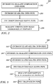
- FIG. 2 is a simplified flow chart of a method 200 for sealing a pipeline, with reference to Fig. 1A .
- a sealant composition such as sealant composition 102 is introduced to pipeline 106 in a sealant composition introducing step 202. This is performed from one end of the pipe or from a manhole or vertical.
- gel pig 104 is introduced from the same end of the pipe as the sealant composition or from a manhole or vertical, in a gel pig composition introducing step 202.
- the combination of the sealant composition 102 and gel pig 104 is termed herein a "pig train".
- the pig train travels along the pipe in a travelling step 206 to site 108 of the leakage.
- the sealant composition is operative to seal the leakage in a sealing step 208. It typically takes a few minutes to several hours until the seal is fully cured.
- gel pig 104 is of approximately the same diameter as the inner diameter of the pipe and is typically 0.5 -10 diameters in length.
- the physical properties of the gel pig appear in Table 4.
- FIG. 3 is a simplified flow chart of another method 300 for sealing a pipeline, with reference to Fig. 1 .
- a first gel pig 114 is introduced to the pipe in an introducing pig step 302.
- the gel pig is introduced from a fire hydrant, from a manhole, vertical, lateral pipe, communication pipe or from a branch pipe.
- a sealant composition, such as sealant composition 102 is introduced to pipeline 106, from a fire hydrant, from a manhole, vertical, lateral pipe, communication pipe or from a branch pipe, in a sealant composition introducing step 304. This is performed from one end of the pipe or from a manhole or vertical.
- a second gel pig 104 is introduced from the same end of the pipe, from a fire hydrant, from a manhole, vertical, lateral pipe, communication pipe or from a branch pipe, as the sealant composition, in a second gel pig composition introducing step 306.
- the combination of the sealants composition 102 and gel pigs 114, 104 is termed herein a "pig train".
- the pig train travels along the pipe in a travelling step 308 to site 108 of the leakage.
- the sealant composition is operative to seal the leakage in a sealing step 310. It typically takes a few minutes to several hours until the seal is fully cured.
- gel pigs 104, 114 are of approximately the same diameter as the inner diameter of the pipe and is typically 0.5 -10 diameters in length.
- the physical properties of the front gel pig 114 appear in Table 5.
- the pig train is typically recovered from the pipeline in an exit pipe step 312.
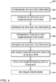
- Fig. 4 is a simplified flow chart of another method 400 for sealing a pipeline, with reference to Fig. 1C .
- a first gel pig 118 is introduced to the pipe in a first introducing pig step 402.
- the gel pig is introduced from a fire hydrant, from a manhole, vertical, lateral pipe, communication pipe or from a branch pipe.
- a sealant composition, such as sealant composition 116 is introduced to pipeline 106 in a first sealant composition introducing step 404. This is performed from one end of the pipe or from a manhole from a fire hydrant, lateral pipe, communication pipe or from a branch pipe or vertical.
- a second gel pig 114 is introduced from the same end of the pipe as the first sealant composition or from a fire hydrant, from a manhole, vertical, lateral pipe, communication pipe or from a branch pipe, in a second gel pig composition introducing step 406.
- a second sealant composition such as sealant composition 102 is introduced to pipeline 106 from a fire hydrant, from a manhole, vertical, lateral pipe, communication pipe or from a branch pipe in a second sealant composition introducing step 408. This is performed from one end of the pipe or from a manhole or vertical.
- a third gel pig 104 is introduced from the same end of the pipe as the first and second sealant composition from a fire hydrant, from a manhole, vertical, lateral pipe, communication pipe or from a branch pipe., in a third gel pig composition introducing step 410.
- the combination of the sealants compositions 102, 116 and gel pigs 118, 114 and 104 is termed herein a "pig train".
- the pig train travels along the pipe in a travelling step 412 to site 108 of the leakage.
- the sealant composition(s) is/are operative to seal the leakage in a sealing step 414. It typically takes a few minutes to several hours until the seal is fully cured.
- gel pigs 104, 114, 118 are of approximately the same diameter as the inner diameter of the pipe and is typically 0.5 -10 diameters in length.
- the physical properties of the front/middle gel pig 118/114 appear in Table 5.
- the pig train is typically recovered from the pipeline in an exit pipe step 416.
- one or more of the gel pigs are replaced with a polymer pig, such as polyurethane.
- FIG. 5 is a simplified pictorial illustration showing a system 500 for sealing a pipeline, in accordance with an embodiment of the present invention.
- System 500 comprises a front gel pig 114 and a real gel pig 104.
- a sealant composition 102 is disposed between pigs 114 and 104, forming a pig train 120.
- a fluid 502 is inserted into a pipeline 501, from a fire hydrant, from a manhole, vertical, lateral pipe, communication pipe or from a branch pipe, and a first pressure P 1 506 is applied to fluid 502. Additionally, a second counter-pressure P 2 , 508 is applied to a second fluid 504. Typically, P 1 is much greater than P 2 .
- the average velocity of pig train 120 is determined by the fluid properties and a pressure difference (P 1 -P 2 ).
- Pressure P1 is introduced by a pump 512, pressure from an existing network or any other suitable pressure introducing means, known in the art.
- the pressure P1 is typically regulated by control means, as are known in the art.
- Pressure P2 is introduced by any suitable passive means, such as a pressure relief valve 514, a discharge valve, a pressure regulator or the like.
- a gel pig is formed according to the following method.
- the physical properties of the gel pigs appear as in tables 2 and/or 3.
- hydrophobic solvents are liquid oils originating from vegetable, marine or animal sources.
- the canola oil exemplified is replaced by any suitable liquid oil including saturated, unsaturated or polyunsaturated oils.
- the unsaturated oil is olive oil, corn oil, soybean oil, cottonseed oil, coconut oil, sesame oil, sunflower oil, borage seed oil, syzigium aromaticum oil, hempseed oil, herring oil, cod-liver oil, salmon oil, flaxseed oil, wheat germ oil, canola oil, evening primrose oils or mixtures thereof, in any proportion.
- the silica exemplified is replaced by a) microsponges, b) silica, c) mineral bodies like zeolite, bentonite, (iii) graphite, including polymers, dendrimers and liposomes, or mixtures thereof, in any proportion.
- the aluminum hydroxide exemplified is replaced by minerals such as aluminum phosphate and calcium phosphate or mixtures thereof, in any proportion.
- the hydroxyethyl cellulose exemplified is replaced by any at least one polymeric additive selected from the group consisting of polysaccharides, natural polysaccharides, derivatives thereof, modified poysacharides, derivatives thereof, starch, dextrin, glycogen, cellulose and chitin, glycosaminoglycans (GAG's), chondroitin sulphate, dermatan sulphate, keratan sulphate, heparan sulphate, heparin, and hyaluronan, amylose and amylopectine, cellulose derivatives, xanthan gum, sodium CMC, methylcellulose, and hydroxyl propyl methyl cellulose or mixtures thereof, in any proportion.
- polymeric additive selected from the group consisting of polysaccharides, natural polysaccharides, derivatives thereof, modified poysacharides, derivatives thereof, starch, dextrin, glycogen, cellulose and chitin, glycos
- surfactants are an ionic surfactant, a nonionic surfactant, a hydrophobic surfactant or mixtures thereof, in any proportion.
- Exemplary hygroscopic agents that can be used in accordance with one or more embodiments include, for example, naturally-occurring polymeric materials, such as locust bean gum, sodium alginate, sodium caseinate, egg albumin, gelatin agar, carrageenan gum, sodium alginate, xanthan gum, quince seed extract, tragacanth gum, guar gum, starch, chemically modified starches and the like, semi-synthetic polymeric materials such as cellulose ethers (e.g.
- hydroxyethyl cellulose methyl cellulose, carboxymethyl cellulose, hydroxy propylmethyl cellulose
- guar gum hydroxypropyl guar gum
- soluble starch cationic celluloses, cationic guars, and the like
- synthetic polymeric materials such as carboxyvinyl polymers, polyvinylpyrrolidone, polyvinyl alcohol, polyacrylic acid polymers, polymethacrylic acid polymers, polyvinyl acetate polymers, polyvinyl chloride polymers, polyvinylidene chloride polymers and the like. Mixtures of the above compounds are contemplated.
- a base is selected from sodium hydroxide, magnesium hydroxide, aluminum hydroxide, potassium hydroxide and combinations thereof.
- Table 2 Physical and Chemical properties of rear gel pig minimum maximum Viscosity cPs 5 10000 Density g/cm 3 0.8 1.2
- Table 3 Physical and Chemical properties of front gel pig minimum maximum Viscosity cPs 5 10000 Density g/cm 3 0.8 1.5
Claims (14)
- System (100) zum Aushärten wenistens einer Undichtigkeitsstelle (108) in einer Rohrleitung (106), wobei das System (100) umfasst:a) wenigstens ein nicht-abschleifender, vollkommen spülbarer Gel-Molch (104), umfassend:i. eine feuchtigkeitsbindende Komponente in einer Konzentration von 1-10 Gewichtsprozent;ii. ein Tensid in einer Konzentration von 0-8 Gewichtsprozent;iii. ein Trägerfluid in einer Konzentration von 70-95 Gewichtsprozent;iv. eine Base in einer Konzentration von 0-20 Gewichtsprozent;v. ein partikuläres Material in einer Konzentration von 0-2 Gewichtsprozent;wobei sich die Komponenten i. bis v. auf insgesamt 100 Gewichtsprozent belaufen;b) wenigstens eine Dichtmittelzusammensetzung (102);
wobei der wenigstens eine Gel-Molch (104) und die wenigstens eine Dichtmittelzusammensetzung (102) einen Molch- (104) -Zug bilden, der angepasst ist, um sich entlang der Rohrleitung (106) zu einem Bereich der wenigstens einen Undichtigkeit (108) zu bewegen und um die wenigstens eine Undichtigkeit (108) abzudichten. - System (100) nach Anspruch 1, wobei der wenigstens eine Gel-Molch (104) einen Gel-Molch (104) umfasst und die wenigstens eine Dichtmittelzusammensetzung (102) eine Dichtmittelzusammensetzung (102) umfasst.
- System (120) nach Anspruch 1, wobei der wenigstens eine Gel-Molch (104) zwei Gel-Molche (104, 114) umfasst und die wenigstens eine Dichtmittelzusammensetzung (102) eine Dichtmittelzusammensetzung (102) umfasst.
- System (100) nach Anspruch 1, wobei der wenigstens eine Gel-Molch (104) drei Gel-Molche (104, 114, 118) umfasst und die wenigstens eine Dichtmittelzusammensetzung (102) zwei Dichtmittelzusammensetzungen (102, 116) umfasst.
- System (100) nach Anspruch 1, wobei der Molch-Zug angepasst ist, sich mit einer Geschwindigkeit von 0,01 bis 10 m/s entlang der Rohrleitung (106) zu bewegen.
- System (100) nach Anspruch 2, wobei der wenigstens eine Gel-Molch (104) einen hinteren Molch (104) umfasst.
- System (120) nach Anspruch 3, wobei wenigstens einer der zwei Molche (104, 114) einen mittleren Durchmesser von wenigstens 5 %, bevorzugt 10 % weniger als ein Innendurchmesser der Rohrleitung (106) aufweist.
- System nach Anspruch 1, wobei die Basis Aluminiumhydroxid ist oder aus Mineralien wie z.B. Aluminiumphosphat und Calciumphosphat oder Mischungen davon ausgewählt ist.
- System nach Anspruch 1, wobei das Tensid ausgewählt ist aus einem ionischen Tensid, einem nichtionischen Tensid, einem hydrophoben Tensid oder Mischungen davon.
- System (100) nach Anspruch 1, wobei der wenigstens eine Gel-Molch (104) einen hinteren Molch (104) und einen vorderen Molch (114) mit unterschiedlichen Zusammensetzungen umfasst.
- System (100) nach Anspruch 1, wobei der Molch-Zug angepasst ist, mit einem Innenprofil der Rohrleitung (106) übereinzustimmen.
- System (100) nach Anspruch 1, wobei das System (100) ferner ein druckbeaufschlagtes Fluid zum Antreiben des Systems (100) von einem ersten Ende davon entlang der Rohrleitung (106) umfasst, wobei bevorzugt das druckbeaufschlagte Fluid bei einem Druck von 1-150 bar ist und wobei das System bevorzugt ferner ein entgegen-druckbeaufschlagtes Fluid umfasst zum entgegen-druckbeaufschlagen des Molch-Zugs von einem zweiten Ende davon.
- System (100) nach Anspruch 11, wobei das druckbeaufschlagte Fluid ausgewählt ist aus Gas, Flüssigkeit und einem dreiphasigen Fluid.
- System (100) nach Anspruch 10, wobei der Molch-Zug angepasst ist, um eine Umgehung eines Antriebsprodukts um mehr als 30 % zu verhindern, wobei der Molch-Zug bevorzugt auch angepasst ist, aus der Rohrleitung über eine Leitung mit weniger als 50,8 mm (2 Inch) Durchmesser bei einem Druck von weniger als 3 bar extrahiert zu werden.
Applications Claiming Priority (2)
| Application Number | Priority Date | Filing Date | Title |
|---|---|---|---|
| US201462093862P | 2014-12-18 | 2014-12-18 | |
| PCT/IL2015/000051 WO2016098093A1 (en) | 2014-12-18 | 2015-12-16 | Systems and method for sealing pipelines using a gel pig |
Publications (3)
| Publication Number | Publication Date |
|---|---|
| EP3234436A1 EP3234436A1 (de) | 2017-10-25 |
| EP3234436A4 EP3234436A4 (de) | 2018-12-05 |
| EP3234436B1 true EP3234436B1 (de) | 2021-11-03 |
Family
ID=56126050
Family Applications (2)
| Application Number | Title | Priority Date | Filing Date |
|---|---|---|---|
| EP15869459.6A Active EP3234436B1 (de) | 2014-12-18 | 2015-12-16 | Systeme zum abdichten von kanalrohren mit einem gelmolch |
| EP15869460.4A Active EP3234437B1 (de) | 2014-12-18 | 2015-12-16 | Verfahren zum abdichten von rohrleitungen mit einem gelmolch |
Family Applications After (1)
| Application Number | Title | Priority Date | Filing Date |
|---|---|---|---|
| EP15869460.4A Active EP3234437B1 (de) | 2014-12-18 | 2015-12-16 | Verfahren zum abdichten von rohrleitungen mit einem gelmolch |
Country Status (10)
| Country | Link |
|---|---|
| US (2) | US10302235B2 (de) |
| EP (2) | EP3234436B1 (de) |
| CN (2) | CN107614956B (de) |
| BR (2) | BR112017013006A2 (de) |
| CO (2) | CO2017007190A2 (de) |
| IL (2) | IL252785B (de) |
| MX (2) | MX367586B (de) |
| RU (2) | RU2697911C2 (de) |
| WO (2) | WO2016098093A1 (de) |
| ZA (1) | ZA201704842B (de) |
Families Citing this family (11)
| Publication number | Priority date | Publication date | Assignee | Title |
|---|---|---|---|---|
| BR102018013965B1 (pt) * | 2018-07-09 | 2022-03-29 | Petróleo Brasileiro S.A. - Petrobras | Dispositivo e método para reparo de mangueira de umbilicais |
| CA3134895A1 (en) | 2019-04-02 | 2020-10-08 | Curapipe System Ltd. | Systems and methods for sealing pipelines |
| WO2020202134A1 (en) * | 2019-04-02 | 2020-10-08 | Curapipe System Ltd. | Methods and systems for sealing a service pipe |
| GB2584653B (en) * | 2019-06-07 | 2023-04-19 | Bae Systems Plc | Improvements in and relating to ice pigging |
| AU2020288871A1 (en) * | 2019-06-07 | 2022-01-06 | Bae Systems Plc | Flowable slush of frozen particles for ice pigging |
| EP3747559A1 (de) * | 2019-06-07 | 2020-12-09 | BAE SYSTEMS plc | Fliessfähiger schlick gefrorener partikel für eismolchung |
| GB201910862D0 (en) | 2019-07-30 | 2019-09-11 | Hydrosave Uk Ltd | Adaptor device for liquid supply |
| CN110408059A (zh) * | 2019-08-05 | 2019-11-05 | 海洋石油工程股份有限公司 | 海底管道隔离封堵清管用材料及其制备方法 |
| GB2589157B (en) * | 2020-04-03 | 2022-05-25 | Origin Tech Ltd | A method of inhibiting leakage of a fluid through a defect in a wall of a pipe |
| CN112981569B (zh) * | 2021-02-03 | 2022-04-12 | 新疆金大禹环境科技有限公司 | 一种化纤生产加工用导流全包式上油辊 |
| US20240125420A1 (en) * | 2021-02-18 | 2024-04-18 | Curapipe System Ltd. | Launcher system, apparatus and method for launching gel pig trains |
Family Cites Families (30)
| Publication number | Priority date | Publication date | Assignee | Title |
|---|---|---|---|---|
| US3523826A (en) | 1967-07-17 | 1970-08-11 | Petrolite Corp | Process of cleaning piping systems |
| US4003393A (en) * | 1973-02-14 | 1977-01-18 | The Dow Chemical Company | Gel-like composition for use as a pig in a pipeline |
| US4379722A (en) | 1978-08-09 | 1983-04-12 | Shell Oil Company | Pipeline gel plug |
| US4383783A (en) * | 1978-09-18 | 1983-05-17 | Shell Oil Company | Pipeline gel plug |
| US4216026A (en) | 1979-02-05 | 1980-08-05 | Shell Oil Company | System for removing fluid and debris from pipelines |
| US4252465A (en) | 1979-02-13 | 1981-02-24 | Shell Oil Company | Pipeline gel plug |
| US4543131A (en) * | 1979-11-20 | 1985-09-24 | The Dow Chemical Company | Aqueous crosslinked gelled pigs for cleaning pipelines |
| US4254559A (en) * | 1980-02-19 | 1981-03-10 | The Dow Chemical Company | Method for drying pipelines |
| US4321968A (en) | 1980-05-22 | 1982-03-30 | Phillips Petroleum Company | Methods of using aqueous gels |
| US4416703A (en) | 1981-11-20 | 1983-11-22 | Shell Oil Company | System for removing debris from pipelines |
| US4582091A (en) * | 1982-02-02 | 1986-04-15 | The British Petroleum Company P.L.C. | Leak sealing method |
| US5067565A (en) * | 1989-03-10 | 1991-11-26 | Halliburton Company | Crosslinkable cellulose derivatives |
| US5122549A (en) * | 1989-03-10 | 1992-06-16 | Halliburton Company | Crosslinkable cellulose derivatives |
| EP0401936B1 (de) * | 1989-06-06 | 1994-10-05 | Sofitech N.V. | Verfahren und Vorrichtung zum zeitweiligen Abdichten von Rohrleitungen |
| US5215781A (en) * | 1991-04-10 | 1993-06-01 | Atlantic Richfield Company | Method for treating tubulars with a gelatin pig |
| GB9301767D0 (en) * | 1993-01-29 | 1993-03-17 | Amec Utilities Ltd | A method of lining pipe |
| US5358043A (en) * | 1993-03-22 | 1994-10-25 | Phillips Petroleum Company | Gelling compositions useful for oil field applications |
| US5346339A (en) * | 1993-06-16 | 1994-09-13 | Halliburton Company | Pipeline cleaning process |
| US7084094B2 (en) | 1999-12-29 | 2006-08-01 | Tr Oil Services Limited | Process for altering the relative permeability if a hydrocarbon-bearing formation |
| US8273693B2 (en) * | 2001-12-12 | 2012-09-25 | Clearwater International Llc | Polymeric gel system and methods for making and using same in hydrocarbon recovery |
| MXPA05011720A (es) * | 2003-05-02 | 2006-01-23 | Tdw Delaware Inc | Aparatos, sistemas y metodos para obturar una tuberia de alta temperatura. |
| RU2343999C2 (ru) * | 2004-06-18 | 2009-01-20 | Пластокор, Инк. | Система и способ покрытия труб |
| US7795185B2 (en) * | 2006-07-27 | 2010-09-14 | Halliburton Energy Services, Inc. | Magnesium peroxide difunctional components for cellulose derivatives and associated methods |
| US7748456B2 (en) * | 2006-08-11 | 2010-07-06 | Halliburton Energy Services, Inc. | Dual functional components and associated methods |
| US8008236B2 (en) * | 2006-10-27 | 2011-08-30 | Halliburton Energy Services, Inc. | Ortho ester breakers for viscoelastic surfactant gels and associated methods |
| IL180474A (en) | 2007-01-01 | 2013-12-31 | Curapipe Ltd | A process and structure for blocking "in place" of pipeline leaks |
| US20080217012A1 (en) * | 2007-03-08 | 2008-09-11 | Bj Services Company | Gelled emulsions and methods of using the same |
| US20080277112A1 (en) | 2007-05-10 | 2008-11-13 | Halliburton Energy Services, Inc. | Methods for stimulating oil or gas production using a viscosified aqueous fluid with a chelating agent to remove calcium carbonate and similar materials from the matrix of a formation or a proppant pack |
| US8065905B2 (en) * | 2007-06-22 | 2011-11-29 | Clearwater International, Llc | Composition and method for pipeline conditioning and freezing point suppression |
| GB0906541D0 (en) * | 2009-04-16 | 2009-05-20 | Brinker Technology Ltd | Delivery method and compositions |
-
2015
- 2015-12-16 MX MX2017007991A patent/MX367586B/es active IP Right Grant
- 2015-12-16 MX MX2017007992A patent/MX367585B/es active IP Right Grant
- 2015-12-16 IL IL252785A patent/IL252785B/en unknown
- 2015-12-16 WO PCT/IL2015/000051 patent/WO2016098093A1/en active Application Filing
- 2015-12-16 EP EP15869459.6A patent/EP3234436B1/de active Active
- 2015-12-16 CN CN201580076444.6A patent/CN107614956B/zh active Active
- 2015-12-16 RU RU2017123876A patent/RU2697911C2/ru active
- 2015-12-16 BR BR112017013006A patent/BR112017013006A2/pt not_active Application Discontinuation
- 2015-12-16 RU RU2017123877A patent/RU2697595C2/ru active
- 2015-12-16 BR BR112017013023A patent/BR112017013023A2/pt not_active Application Discontinuation
- 2015-12-16 WO PCT/IL2015/000052 patent/WO2016098094A1/en active Application Filing
- 2015-12-16 CN CN201580076557.6A patent/CN107614957B/zh active Active
- 2015-12-16 EP EP15869460.4A patent/EP3234437B1/de active Active
- 2015-12-16 US US15/535,753 patent/US10302235B2/en active Active
- 2015-12-18 US US15/535,991 patent/US10302236B2/en active Active
-
2017
- 2017-06-08 IL IL252784A patent/IL252784B/en unknown
- 2017-07-17 ZA ZA2017/04842A patent/ZA201704842B/en unknown
- 2017-07-18 CO CONC2017/0007190A patent/CO2017007190A2/es unknown
- 2017-07-18 CO CONC2017/0007193A patent/CO2017007193A2/es unknown
Non-Patent Citations (1)
| Title |
|---|
| None * |
Also Published As
Similar Documents
| Publication | Publication Date | Title |
|---|---|---|
| EP3234436B1 (de) | Systeme zum abdichten von kanalrohren mit einem gelmolch | |
| US11009173B2 (en) | Method for sealing pipelines using a gel pig | |
| US11009175B2 (en) | Systems and method for sealing pipelines using a gel pig | |
| CN104534167A (zh) | 触变泥浆的减阻方法 | |
| AU2015408176A1 (en) | Use of crosslinked polymer system for mitigation of annular pressure buildup | |
| EP3640517B1 (de) | Verfahren zur härtung von leckagen in rohrleitungen | |
| RU2314331C1 (ru) | Жидкость для глушения скважин без твердой фазы | |
| US11786944B2 (en) | Method and kit for removing trapped hydrocarbons | |
| US20240125420A1 (en) | Launcher system, apparatus and method for launching gel pig trains | |
| NO157744B (no) | Fremgangsmte for innvendig rengjing av rledninger. | |
| US11867337B2 (en) | Systems and methods for sealing pipelines | |
| CN116063992A (zh) | 一种利用油基钻屑的堵漏组合物及其应用方法 | |
| CN106007637A (zh) | 用于顶管管节壁后注入的塑化剂 |
Legal Events
| Date | Code | Title | Description |
|---|---|---|---|
| STAA | Information on the status of an ep patent application or granted ep patent |
Free format text: STATUS: THE INTERNATIONAL PUBLICATION HAS BEEN MADE |
|
| PUAI | Public reference made under article 153(3) epc to a published international application that has entered the european phase |
Free format text: ORIGINAL CODE: 0009012 |
|
| STAA | Information on the status of an ep patent application or granted ep patent |
Free format text: STATUS: REQUEST FOR EXAMINATION WAS MADE |
|
| 17P | Request for examination filed |
Effective date: 20170714 |
|
| AK | Designated contracting states |
Kind code of ref document: A1 Designated state(s): AL AT BE BG CH CY CZ DE DK EE ES FI FR GB GR HR HU IE IS IT LI LT LU LV MC MK MT NL NO PL PT RO RS SE SI SK SM TR |
|
| AX | Request for extension of the european patent |
Extension state: BA ME |
|
| DAV | Request for validation of the european patent (deleted) | ||
| DAX | Request for extension of the european patent (deleted) | ||
| REG | Reference to a national code |
Ref country code: DE Ref legal event code: R079 Ref document number: 602015074775 Country of ref document: DE Free format text: PREVIOUS MAIN CLASS: F16L0055128000 Ipc: F16L0055164000 |
|
| RIN1 | Information on inventor provided before grant (corrected) |
Inventor name: PAZ, PETER Inventor name: NATAPOV BORIS Inventor name: UKHANOV, REONALD Inventor name: PERSTNEV, SAMUEL Inventor name: PERSTNEV, ALEXANDER |
|
| A4 | Supplementary search report drawn up and despatched |
Effective date: 20181029 |
|
| RIC1 | Information provided on ipc code assigned before grant |
Ipc: F16L 55/42 20060101ALI20181023BHEP Ipc: F16L 55/1645 20060101ALI20181023BHEP Ipc: F16L 55/164 20060101AFI20181023BHEP Ipc: C09K 3/12 20060101ALI20181023BHEP |
|
| STAA | Information on the status of an ep patent application or granted ep patent |
Free format text: STATUS: EXAMINATION IS IN PROGRESS |
|
| 17Q | First examination report despatched |
Effective date: 20190801 |
|
| STAA | Information on the status of an ep patent application or granted ep patent |
Free format text: STATUS: EXAMINATION IS IN PROGRESS |
|
| GRAP | Despatch of communication of intention to grant a patent |
Free format text: ORIGINAL CODE: EPIDOSNIGR1 |
|
| STAA | Information on the status of an ep patent application or granted ep patent |
Free format text: STATUS: GRANT OF PATENT IS INTENDED |
|
| INTG | Intention to grant announced |
Effective date: 20210618 |
|
| GRAS | Grant fee paid |
Free format text: ORIGINAL CODE: EPIDOSNIGR3 |
|
| GRAA | (expected) grant |
Free format text: ORIGINAL CODE: 0009210 |
|
| STAA | Information on the status of an ep patent application or granted ep patent |
Free format text: STATUS: THE PATENT HAS BEEN GRANTED |
|
| AK | Designated contracting states |
Kind code of ref document: B1 Designated state(s): AL AT BE BG CH CY CZ DE DK EE ES FI FR GB GR HR HU IE IS IT LI LT LU LV MC MK MT NL NO PL PT RO RS SE SI SK SM TR |
|
| REG | Reference to a national code |
Ref country code: GB Ref legal event code: FG4D |
|
| REG | Reference to a national code |
Ref country code: AT Ref legal event code: REF Ref document number: 1444250 Country of ref document: AT Kind code of ref document: T Effective date: 20211115 Ref country code: CH Ref legal event code: EP |
|
| REG | Reference to a national code |
Ref country code: IE Ref legal event code: FG4D |
|
| REG | Reference to a national code |
Ref country code: DE Ref legal event code: R096 Ref document number: 602015074775 Country of ref document: DE |
|
| REG | Reference to a national code |
Ref country code: LT Ref legal event code: MG9D |
|
| REG | Reference to a national code |
Ref country code: NL Ref legal event code: MP Effective date: 20211103 |
|
| REG | Reference to a national code |
Ref country code: AT Ref legal event code: MK05 Ref document number: 1444250 Country of ref document: AT Kind code of ref document: T Effective date: 20211103 |
|
| PG25 | Lapsed in a contracting state [announced via postgrant information from national office to epo] |
Ref country code: RS Free format text: LAPSE BECAUSE OF FAILURE TO SUBMIT A TRANSLATION OF THE DESCRIPTION OR TO PAY THE FEE WITHIN THE PRESCRIBED TIME-LIMIT Effective date: 20211103 Ref country code: LT Free format text: LAPSE BECAUSE OF FAILURE TO SUBMIT A TRANSLATION OF THE DESCRIPTION OR TO PAY THE FEE WITHIN THE PRESCRIBED TIME-LIMIT Effective date: 20211103 Ref country code: FI Free format text: LAPSE BECAUSE OF FAILURE TO SUBMIT A TRANSLATION OF THE DESCRIPTION OR TO PAY THE FEE WITHIN THE PRESCRIBED TIME-LIMIT Effective date: 20211103 Ref country code: BG Free format text: LAPSE BECAUSE OF FAILURE TO SUBMIT A TRANSLATION OF THE DESCRIPTION OR TO PAY THE FEE WITHIN THE PRESCRIBED TIME-LIMIT Effective date: 20220203 Ref country code: AT Free format text: LAPSE BECAUSE OF FAILURE TO SUBMIT A TRANSLATION OF THE DESCRIPTION OR TO PAY THE FEE WITHIN THE PRESCRIBED TIME-LIMIT Effective date: 20211103 |
|
| PG25 | Lapsed in a contracting state [announced via postgrant information from national office to epo] |
Ref country code: IS Free format text: LAPSE BECAUSE OF FAILURE TO SUBMIT A TRANSLATION OF THE DESCRIPTION OR TO PAY THE FEE WITHIN THE PRESCRIBED TIME-LIMIT Effective date: 20220303 Ref country code: SE Free format text: LAPSE BECAUSE OF FAILURE TO SUBMIT A TRANSLATION OF THE DESCRIPTION OR TO PAY THE FEE WITHIN THE PRESCRIBED TIME-LIMIT Effective date: 20211103 Ref country code: PT Free format text: LAPSE BECAUSE OF FAILURE TO SUBMIT A TRANSLATION OF THE DESCRIPTION OR TO PAY THE FEE WITHIN THE PRESCRIBED TIME-LIMIT Effective date: 20220303 Ref country code: PL Free format text: LAPSE BECAUSE OF FAILURE TO SUBMIT A TRANSLATION OF THE DESCRIPTION OR TO PAY THE FEE WITHIN THE PRESCRIBED TIME-LIMIT Effective date: 20211103 Ref country code: NO Free format text: LAPSE BECAUSE OF FAILURE TO SUBMIT A TRANSLATION OF THE DESCRIPTION OR TO PAY THE FEE WITHIN THE PRESCRIBED TIME-LIMIT Effective date: 20220203 Ref country code: NL Free format text: LAPSE BECAUSE OF FAILURE TO SUBMIT A TRANSLATION OF THE DESCRIPTION OR TO PAY THE FEE WITHIN THE PRESCRIBED TIME-LIMIT Effective date: 20211103 Ref country code: LV Free format text: LAPSE BECAUSE OF FAILURE TO SUBMIT A TRANSLATION OF THE DESCRIPTION OR TO PAY THE FEE WITHIN THE PRESCRIBED TIME-LIMIT Effective date: 20211103 Ref country code: HR Free format text: LAPSE BECAUSE OF FAILURE TO SUBMIT A TRANSLATION OF THE DESCRIPTION OR TO PAY THE FEE WITHIN THE PRESCRIBED TIME-LIMIT Effective date: 20211103 Ref country code: GR Free format text: LAPSE BECAUSE OF FAILURE TO SUBMIT A TRANSLATION OF THE DESCRIPTION OR TO PAY THE FEE WITHIN THE PRESCRIBED TIME-LIMIT Effective date: 20220204 Ref country code: ES Free format text: LAPSE BECAUSE OF FAILURE TO SUBMIT A TRANSLATION OF THE DESCRIPTION OR TO PAY THE FEE WITHIN THE PRESCRIBED TIME-LIMIT Effective date: 20211103 |
|
| PG25 | Lapsed in a contracting state [announced via postgrant information from national office to epo] |
Ref country code: SM Free format text: LAPSE BECAUSE OF FAILURE TO SUBMIT A TRANSLATION OF THE DESCRIPTION OR TO PAY THE FEE WITHIN THE PRESCRIBED TIME-LIMIT Effective date: 20211103 Ref country code: SK Free format text: LAPSE BECAUSE OF FAILURE TO SUBMIT A TRANSLATION OF THE DESCRIPTION OR TO PAY THE FEE WITHIN THE PRESCRIBED TIME-LIMIT Effective date: 20211103 Ref country code: RO Free format text: LAPSE BECAUSE OF FAILURE TO SUBMIT A TRANSLATION OF THE DESCRIPTION OR TO PAY THE FEE WITHIN THE PRESCRIBED TIME-LIMIT Effective date: 20211103 Ref country code: EE Free format text: LAPSE BECAUSE OF FAILURE TO SUBMIT A TRANSLATION OF THE DESCRIPTION OR TO PAY THE FEE WITHIN THE PRESCRIBED TIME-LIMIT Effective date: 20211103 Ref country code: DK Free format text: LAPSE BECAUSE OF FAILURE TO SUBMIT A TRANSLATION OF THE DESCRIPTION OR TO PAY THE FEE WITHIN THE PRESCRIBED TIME-LIMIT Effective date: 20211103 Ref country code: CZ Free format text: LAPSE BECAUSE OF FAILURE TO SUBMIT A TRANSLATION OF THE DESCRIPTION OR TO PAY THE FEE WITHIN THE PRESCRIBED TIME-LIMIT Effective date: 20211103 |
|
| REG | Reference to a national code |
Ref country code: CH Ref legal event code: PL |
|
| REG | Reference to a national code |
Ref country code: DE Ref legal event code: R097 Ref document number: 602015074775 Country of ref document: DE |
|
| PG25 | Lapsed in a contracting state [announced via postgrant information from national office to epo] |
Ref country code: MC Free format text: LAPSE BECAUSE OF FAILURE TO SUBMIT A TRANSLATION OF THE DESCRIPTION OR TO PAY THE FEE WITHIN THE PRESCRIBED TIME-LIMIT Effective date: 20211103 |
|
| PLBE | No opposition filed within time limit |
Free format text: ORIGINAL CODE: 0009261 |
|
| STAA | Information on the status of an ep patent application or granted ep patent |
Free format text: STATUS: NO OPPOSITION FILED WITHIN TIME LIMIT |
|
| REG | Reference to a national code |
Ref country code: BE Ref legal event code: MM Effective date: 20211231 |
|
| 26N | No opposition filed |
Effective date: 20220804 |
|
| PG25 | Lapsed in a contracting state [announced via postgrant information from national office to epo] |
Ref country code: LU Free format text: LAPSE BECAUSE OF NON-PAYMENT OF DUE FEES Effective date: 20211216 Ref country code: AL Free format text: LAPSE BECAUSE OF FAILURE TO SUBMIT A TRANSLATION OF THE DESCRIPTION OR TO PAY THE FEE WITHIN THE PRESCRIBED TIME-LIMIT Effective date: 20211103 |
|
| PG25 | Lapsed in a contracting state [announced via postgrant information from national office to epo] |
Ref country code: SI Free format text: LAPSE BECAUSE OF FAILURE TO SUBMIT A TRANSLATION OF THE DESCRIPTION OR TO PAY THE FEE WITHIN THE PRESCRIBED TIME-LIMIT Effective date: 20211103 Ref country code: BE Free format text: LAPSE BECAUSE OF NON-PAYMENT OF DUE FEES Effective date: 20211231 |
|
| PG25 | Lapsed in a contracting state [announced via postgrant information from national office to epo] |
Ref country code: LI Free format text: LAPSE BECAUSE OF NON-PAYMENT OF DUE FEES Effective date: 20211231 Ref country code: CH Free format text: LAPSE BECAUSE OF NON-PAYMENT OF DUE FEES Effective date: 20211231 |
|
| PGFP | Annual fee paid to national office [announced via postgrant information from national office to epo] |
Ref country code: IE Payment date: 20221221 Year of fee payment: 8 |
|
| PG25 | Lapsed in a contracting state [announced via postgrant information from national office to epo] |
Ref country code: HU Free format text: LAPSE BECAUSE OF FAILURE TO SUBMIT A TRANSLATION OF THE DESCRIPTION OR TO PAY THE FEE WITHIN THE PRESCRIBED TIME-LIMIT; INVALID AB INITIO Effective date: 20151216 |
|
| PGFP | Annual fee paid to national office [announced via postgrant information from national office to epo] |
Ref country code: TR Payment date: 20230112 Year of fee payment: 8 Ref country code: IT Payment date: 20221228 Year of fee payment: 8 Ref country code: DE Payment date: 20221220 Year of fee payment: 8 |
|
| PG25 | Lapsed in a contracting state [announced via postgrant information from national office to epo] |
Ref country code: CY Free format text: LAPSE BECAUSE OF FAILURE TO SUBMIT A TRANSLATION OF THE DESCRIPTION OR TO PAY THE FEE WITHIN THE PRESCRIBED TIME-LIMIT Effective date: 20211103 |
|
| PGFP | Annual fee paid to national office [announced via postgrant information from national office to epo] |
Ref country code: GB Payment date: 20231220 Year of fee payment: 9 |
|
| PGFP | Annual fee paid to national office [announced via postgrant information from national office to epo] |
Ref country code: FR Payment date: 20231220 Year of fee payment: 9 |
|
| PG25 | Lapsed in a contracting state [announced via postgrant information from national office to epo] |
Ref country code: MK Free format text: LAPSE BECAUSE OF FAILURE TO SUBMIT A TRANSLATION OF THE DESCRIPTION OR TO PAY THE FEE WITHIN THE PRESCRIBED TIME-LIMIT Effective date: 20211103 |