EP3234332B1 - Dispositif de modulation de section d'éjection de gaz - Google Patents
Dispositif de modulation de section d'éjection de gaz Download PDFInfo
- Publication number
- EP3234332B1 EP3234332B1 EP15820230.9A EP15820230A EP3234332B1 EP 3234332 B1 EP3234332 B1 EP 3234332B1 EP 15820230 A EP15820230 A EP 15820230A EP 3234332 B1 EP3234332 B1 EP 3234332B1
- Authority
- EP
- European Patent Office
- Prior art keywords
- nozzle
- needle
- upstream end
- internal housing
- upstream
- Prior art date
- Legal status (The legal status is an assumption and is not a legal conclusion. Google has not performed a legal analysis and makes no representation as to the accuracy of the status listed.)
- Active
Links
- 238000011144 upstream manufacturing Methods 0.000 claims description 68
- 239000003380 propellant Substances 0.000 claims description 35
- 230000000694 effects Effects 0.000 claims description 10
- 239000000463 material Substances 0.000 claims description 6
- 230000007423 decrease Effects 0.000 claims 1
- 239000007789 gas Substances 0.000 description 50
- 239000000567 combustion gas Substances 0.000 description 11
- 238000002485 combustion reaction Methods 0.000 description 9
- 229910052799 carbon Inorganic materials 0.000 description 7
- 230000001133 acceleration Effects 0.000 description 6
- 239000011159 matrix material Substances 0.000 description 5
- OKTJSMMVPCPJKN-UHFFFAOYSA-N Carbon Chemical compound [C] OKTJSMMVPCPJKN-UHFFFAOYSA-N 0.000 description 4
- 239000000919 ceramic Substances 0.000 description 4
- 239000004449 solid propellant Substances 0.000 description 4
- XECAHXYUAAWDEL-UHFFFAOYSA-N acrylonitrile butadiene styrene Chemical compound C=CC=C.C=CC#N.C=CC1=CC=CC=C1 XECAHXYUAAWDEL-UHFFFAOYSA-N 0.000 description 3
- 239000004676 acrylonitrile butadiene styrene Substances 0.000 description 3
- 229920000122 acrylonitrile butadiene styrene Polymers 0.000 description 3
- 229910052782 aluminium Inorganic materials 0.000 description 3
- XAGFODPZIPBFFR-UHFFFAOYSA-N aluminium Chemical compound [Al] XAGFODPZIPBFFR-UHFFFAOYSA-N 0.000 description 3
- 238000013459 approach Methods 0.000 description 3
- 230000002301 combined effect Effects 0.000 description 3
- 239000002131 composite material Substances 0.000 description 3
- 239000007788 liquid Substances 0.000 description 3
- 230000008018 melting Effects 0.000 description 3
- 238000002844 melting Methods 0.000 description 3
- 230000003014 reinforcing effect Effects 0.000 description 3
- 230000003247 decreasing effect Effects 0.000 description 2
- 239000000835 fiber Substances 0.000 description 2
- 238000010304 firing Methods 0.000 description 2
- 230000006870 function Effects 0.000 description 2
- 239000007787 solid Substances 0.000 description 2
- 229920000049 Carbon (fiber) Polymers 0.000 description 1
- 229910000831 Steel Inorganic materials 0.000 description 1
- PPBRXRYQALVLMV-UHFFFAOYSA-N Styrene Chemical compound C=CC1=CC=CC=C1 PPBRXRYQALVLMV-UHFFFAOYSA-N 0.000 description 1
- 239000004411 aluminium Substances 0.000 description 1
- 230000005540 biological transmission Effects 0.000 description 1
- NTXGQCSETZTARF-UHFFFAOYSA-N buta-1,3-diene;prop-2-enenitrile Chemical compound C=CC=C.C=CC#N NTXGQCSETZTARF-UHFFFAOYSA-N 0.000 description 1
- 239000004917 carbon fiber Substances 0.000 description 1
- 238000006243 chemical reaction Methods 0.000 description 1
- 230000004927 fusion Effects 0.000 description 1
- 238000004519 manufacturing process Methods 0.000 description 1
- 229910001092 metal group alloy Inorganic materials 0.000 description 1
- 239000000203 mixture Substances 0.000 description 1
- 239000002296 pyrolytic carbon Substances 0.000 description 1
- 239000011347 resin Substances 0.000 description 1
- 229920005989 resin Polymers 0.000 description 1
- 229910001285 shape-memory alloy Inorganic materials 0.000 description 1
- 239000010959 steel Substances 0.000 description 1
- 230000007704 transition Effects 0.000 description 1
Images


Classifications
-
- F—MECHANICAL ENGINEERING; LIGHTING; HEATING; WEAPONS; BLASTING
- F02—COMBUSTION ENGINES; HOT-GAS OR COMBUSTION-PRODUCT ENGINE PLANTS
- F02K—JET-PROPULSION PLANTS
- F02K9/00—Rocket-engine plants, i.e. plants carrying both fuel and oxidant therefor; Control thereof
- F02K9/80—Rocket-engine plants, i.e. plants carrying both fuel and oxidant therefor; Control thereof characterised by thrust or thrust vector control
- F02K9/86—Rocket-engine plants, i.e. plants carrying both fuel and oxidant therefor; Control thereof characterised by thrust or thrust vector control using nozzle throats of adjustable cross- section
-
- F—MECHANICAL ENGINEERING; LIGHTING; HEATING; WEAPONS; BLASTING
- F02—COMBUSTION ENGINES; HOT-GAS OR COMBUSTION-PRODUCT ENGINE PLANTS
- F02K—JET-PROPULSION PLANTS
- F02K9/00—Rocket-engine plants, i.e. plants carrying both fuel and oxidant therefor; Control thereof
- F02K9/08—Rocket-engine plants, i.e. plants carrying both fuel and oxidant therefor; Control thereof using solid propellants
- F02K9/32—Constructional parts; Details not otherwise provided for
- F02K9/38—Safety devices, e.g. to prevent accidental ignition
-
- F—MECHANICAL ENGINEERING; LIGHTING; HEATING; WEAPONS; BLASTING
- F02—COMBUSTION ENGINES; HOT-GAS OR COMBUSTION-PRODUCT ENGINE PLANTS
- F02K—JET-PROPULSION PLANTS
- F02K9/00—Rocket-engine plants, i.e. plants carrying both fuel and oxidant therefor; Control thereof
- F02K9/42—Rocket-engine plants, i.e. plants carrying both fuel and oxidant therefor; Control thereof using liquid or gaseous propellants
- F02K9/44—Feeding propellants
- F02K9/56—Control
- F02K9/566—Control elements and safety devices, e.g. pressure relief valves
-
- F—MECHANICAL ENGINEERING; LIGHTING; HEATING; WEAPONS; BLASTING
- F02—COMBUSTION ENGINES; HOT-GAS OR COMBUSTION-PRODUCT ENGINE PLANTS
- F02K—JET-PROPULSION PLANTS
- F02K9/00—Rocket-engine plants, i.e. plants carrying both fuel and oxidant therefor; Control thereof
- F02K9/80—Rocket-engine plants, i.e. plants carrying both fuel and oxidant therefor; Control thereof characterised by thrust or thrust vector control
- F02K9/805—Rocket-engine plants, i.e. plants carrying both fuel and oxidant therefor; Control thereof characterised by thrust or thrust vector control servo-mechanisms or control devices therefor
-
- F—MECHANICAL ENGINEERING; LIGHTING; HEATING; WEAPONS; BLASTING
- F02—COMBUSTION ENGINES; HOT-GAS OR COMBUSTION-PRODUCT ENGINE PLANTS
- F02K—JET-PROPULSION PLANTS
- F02K9/00—Rocket-engine plants, i.e. plants carrying both fuel and oxidant therefor; Control thereof
- F02K9/80—Rocket-engine plants, i.e. plants carrying both fuel and oxidant therefor; Control thereof characterised by thrust or thrust vector control
- F02K9/84—Rocket-engine plants, i.e. plants carrying both fuel and oxidant therefor; Control thereof characterised by thrust or thrust vector control using movable nozzles
-
- F—MECHANICAL ENGINEERING; LIGHTING; HEATING; WEAPONS; BLASTING
- F02—COMBUSTION ENGINES; HOT-GAS OR COMBUSTION-PRODUCT ENGINE PLANTS
- F02K—JET-PROPULSION PLANTS
- F02K9/00—Rocket-engine plants, i.e. plants carrying both fuel and oxidant therefor; Control thereof
- F02K9/97—Rocket nozzles
- F02K9/976—Deployable nozzles
-
- F—MECHANICAL ENGINEERING; LIGHTING; HEATING; WEAPONS; BLASTING
- F02—COMBUSTION ENGINES; HOT-GAS OR COMBUSTION-PRODUCT ENGINE PLANTS
- F02K—JET-PROPULSION PLANTS
- F02K9/00—Rocket-engine plants, i.e. plants carrying both fuel and oxidant therefor; Control thereof
- F02K9/97—Rocket nozzles
- F02K9/978—Closures for nozzles; Nozzles comprising ejectable or discardable elements
-
- F—MECHANICAL ENGINEERING; LIGHTING; HEATING; WEAPONS; BLASTING
- F02—COMBUSTION ENGINES; HOT-GAS OR COMBUSTION-PRODUCT ENGINE PLANTS
- F02K—JET-PROPULSION PLANTS
- F02K9/00—Rocket-engine plants, i.e. plants carrying both fuel and oxidant therefor; Control thereof
- F02K9/08—Rocket-engine plants, i.e. plants carrying both fuel and oxidant therefor; Control thereof using solid propellants
- F02K9/10—Shape or structure of solid propellant charges
-
- F—MECHANICAL ENGINEERING; LIGHTING; HEATING; WEAPONS; BLASTING
- F02—COMBUSTION ENGINES; HOT-GAS OR COMBUSTION-PRODUCT ENGINE PLANTS
- F02K—JET-PROPULSION PLANTS
- F02K9/00—Rocket-engine plants, i.e. plants carrying both fuel and oxidant therefor; Control thereof
- F02K9/42—Rocket-engine plants, i.e. plants carrying both fuel and oxidant therefor; Control thereof using liquid or gaseous propellants
- F02K9/60—Constructional parts; Details not otherwise provided for
- F02K9/62—Combustion or thrust chambers
-
- F—MECHANICAL ENGINEERING; LIGHTING; HEATING; WEAPONS; BLASTING
- F05—INDEXING SCHEMES RELATING TO ENGINES OR PUMPS IN VARIOUS SUBCLASSES OF CLASSES F01-F04
- F05D—INDEXING SCHEME FOR ASPECTS RELATING TO NON-POSITIVE-DISPLACEMENT MACHINES OR ENGINES, GAS-TURBINES OR JET-PROPULSION PLANTS
- F05D2240/00—Components
- F05D2240/10—Stators
- F05D2240/12—Fluid guiding means, e.g. vanes
- F05D2240/128—Nozzles
- F05D2240/1281—Plug nozzles
-
- F—MECHANICAL ENGINEERING; LIGHTING; HEATING; WEAPONS; BLASTING
- F05—INDEXING SCHEMES RELATING TO ENGINES OR PUMPS IN VARIOUS SUBCLASSES OF CLASSES F01-F04
- F05D—INDEXING SCHEME FOR ASPECTS RELATING TO NON-POSITIVE-DISPLACEMENT MACHINES OR ENGINES, GAS-TURBINES OR JET-PROPULSION PLANTS
- F05D2260/00—Function
- F05D2260/30—Retaining components in desired mutual position
- F05D2260/31—Retaining bolts or nuts
- F05D2260/311—Retaining bolts or nuts of the frangible or shear type
Definitions
- the present invention relates to the general field of thrusters or rocket engines intended to deliver a thrust for the piloting of vehicles such as missiles, launchers or even satellites, using the principle of propulsion by reaction or by gas ejection. . It relates more specifically, but not exclusively, to the nozzles fitted to solid propellant propellants.
- a solid propellant propellant mainly consists of an envelope containing a propellant block, an igniter and a fixed diverging nozzle.
- the propellant block is pierced by a channel located in the axis of the propellant which serves as a combustion chamber.
- the igniter ignites the propellant at one end of the casing and the combustion of the propellant propagates from the front to the rear of the propellant.
- the propellant burns at a predefined speed producing combustion gases which are expelled through the nozzle.
- the neck section of the nozzle makes it possible to regulate the combustion of the propellant block so as to maintain the desired pressure in the combustion chamber while producing the expected thrust. Also, in the case of a thruster delivering a thrust at a single flow rate, the throat section of the nozzle is unique and predetermined as a function of the desired thrust level.
- a single neck section is not suitable for a thruster having two operating regimes, typically a high flow operation (acceleration) and a low flow operation (cruise) or a thruster intended to fly at varying altitudes.
- a known solution consists in providing the launcher with two separate thrusters: one for the acceleration phase ("boost”) and another for the cruising phase.
- boost acceleration phase
- a known solution has the disadvantage of significantly increasing the cost of the launcher.
- a needle movable in translation is housed inside the nozzle. The position of this needle in the flow of combustion gas determines the passage section of the gases leaving the nozzle and thus adjusts the gas ejection section to the operating regime of the propellant.
- the gas ejection section modulation device of the invention provides a simple, low-cost and space-saving solution enabling two operating modes to be defined for a nozzle, namely a first high-flow operating mode in which the 'partial closure member is axially set back relative to the neck of the nozzle and a second low flow mode of operation in which the partial closure member is more axially advanced relative to the neck.
- the transition from the first operating mode to the second operating mode is achieved by rupture of the retaining element or elements.
- the use of one or more fusible retaining elements in combination with a needle and a needle guide makes it possible to define an economical, simple and reliable architecture for nozzles with variation in throat section, without significantly increasing the mass and the size of the propellant.
- the device for modulating the gas ejection section of the invention makes it possible to dispense with the use of two distinct propellants (a propellant for the acceleration phase ("boost”) and another propellant for the cruising phase) and, therefore, to offer a low-cost propulsion system allowing two operating modes.
- the retaining element or elements are made of a material capable of breaking from a determined temperature.
- a subject of the invention is also a nozzle with a variable neck section comprising a nozzle neck, characterized in that it further comprises a device for modulating a gas ejection section according to the invention, said modulation device being placed in the nozzle upstream of said nozzle neck.
- the nozzle of the invention is of aerospike type, that is to say a nozzle operating without diverging, which reduces both the cost, the mass and the size of the propellant while optimizing the thrust of the machine whatever the operating altitude.
- the invention also relates to a propellant comprising a nozzle with a variable neck section according to the invention.
- the propellant of the invention comprises an envelope containing a propellant charge, the nozzle with variable neck section being connected to the rear bottom of said envelope by an extension or an articulated connection.
- the device for modulating the gas ejection section of the invention can be used with any type of nozzle, in particular with nozzles comprising a divergent or not.
- the figure 1A schematically illustrates in longitudinal section the rear part of a thruster 100 comprising an envelope 110 of revolution surrounding a combustion chamber 111 in which is housed a block of solid propellant 112.
- the chamber 111 opens through the rear bottom 110a of the envelope 110 upstream of an aerospike type nozzle 120.
- aerospike type nozzle 120 By “aerospike” nozzle is meant here a nozzle practically devoid of diverging and which comprises a needle with a convex profile which can emerge at its neck.
- the nozzle 120 is connected to the rear bottom 110a by an extension 113.
- the nozzle 120 can also be directly connected to the rear bottom of the casing of the propellant, that is to say without the extension 113.
- the nozzle can be connected to the rear bottom of the casing of the propellant by an articulated connection , such as a ball joint for example, so as to allow the orientation of the nozzle in several directions relative to the axis of the casing of the propellant.
- an articulated connection such as a ball joint for example
- a device for modulating the gas ejection section 130 is disposed inside the nozzle 120 of the neck 121 of the nozzle 120 ( figure 1B ).
- the modulation device 130 is held in position by two arms 131 and 132 fixed on the internal wall of the nozzle 120.
- the arms 131 and 132 are arranged at 180 ° one of the other, the rest of the circumferential space present around the modulation device being left free to allow the gases coming from the combustion chamber 111 to flow towards the nozzle throat 121.
- the device for modulating the ejection section of gas 130 comprises a needle 133 comprising a rod 1333 extending between an upstream end 1330 and a downstream end 1331, said downstream end 1331 having a decreasing diameter forming a partial closure member for the nozzle throat 121.
- the modulation device 130 also includes a needle guide 134 comprising a wall 1342 delimiting an internal housing 1341 in which the upstream end 1330 of the needle 133 is present.
- the needle guide 134 further comprises a passage 1343 supporting the rod 1333 of the needle and guiding its movements.
- the upstream end 1330 of the needle can slide in the internal housing 1341 of the needle guide 134 between a first position in which said upstream end 1330 of the needle 133 is present in an upstream part 1341a of the internal housing 1341 ( figure 2A ) and a second position in which the upstream end 1330 is present in a downstream part 1341b of the internal housing 1341 ( figure 2B ).
- the shape memory alloys can be used in general to produce the retaining element or elements of the device of the invention, their composition being determined as a function of the target needle release temperature.
- the gas ejection section modulation device 130 is in the configuration shown in the figure 2A , configuration in which the downstream end 1331 of the needle 133 is set back from the nozzle neck 121 in order to generate a strong thrust and adapt to the altitude level encountered in this first flight phase.
- the combustion gases circulating in the nozzle 120 will transmit heat to the pin 135.
- the rupture temperature of the pin 135 Once the rupture temperature of the pin 135 has been reached (melting or softening), it loses its mechanical integrity and no longer plays its role of retaining element of the upstream end 1330 of the needle 133 which, under the effect of suction of the pressure forces generated in the nozzle, moves (translation) in the position illustrated on the figure 2B .
- a first part 135a of the pin 135 then remains in the upstream end 1330 of the needle while a second part 135b remains in the wall 1342 of the needle guide.
- the configuration illustrated on the figure 2B corresponds to the second flight phase of the propellant, called the cruising phase, configuration in which the downstream end 1331 of the needle 133 approaches the nozzle neck 121 in order to generate a reduced thrust adapted to the system needs of this second flight phase.
- the upstream part 1341a of the internal housing 1341 is closed by a plug 1344 made of a material whose thermal conductivity makes it possible to delay the transmission of heat from the gases to the pin and, consequently, the instant at which the pin breaks.
- the plug may in particular be made of carbon / carbon composite material (C / C) comprising a reinforcing texture of carbon fibers densified by a pyrolytic carbon matrix (pyrocarbon), of composite material with low density ceramic matrix (CMC) comprising a reinforcing texture of refractory fibers (carbon or ceramic) densified by an at least partially ceramic matrix or of composite material with an organic matrix (CMO) comprising a reinforcing texture of refractory fibers (carbon or ceramic) densified by an organic matrix (resin) .
- the modulation device can also be used without closing the upstream part 1341a of the internal housing 1341.
- the Figures 3A and 3B illustrate a nozzle 220 which comprises a device for modulating the gas ejection section 230 in accordance with another embodiment of the invention.
- the modulation device 230 differs from the device 130 described above in that the pin 235 which crosses both the upstream end 2330 of the needle and the wall 2342 of the needle guide 234 no longer yields under the effect of heat but d '' a mechanical force exerted on the upstream end 2330 of the needle. More specifically, as illustrated in the figure 3A , the upstream end 2330 of the needle 233 has a shoulder 2335 in contact with the wall 2342 of the needle guide 234 defining the housing internal 2341 in which the upstream end 2330 of the needle 233 is present.
- the gas ejection section modulation device 230 further comprises a gas generator, here a pyrotechnic cartridge 240 housed in the arm 232 of the modulation device.
- the pyrotechnic cartridge 240 is capable of sending, on command, a pressurized gas into the upstream part 2341a of the internal housing 2341 between the upstream bottom 2344 of said internal housing and the shoulder 2335 so as to break the pin 235 and make the end slide. upstream 2330 of the needle 233 towards the downstream part 2341b of the internal housing 2341.
- the pyrotechnic cartridge 240 communicates with the internal housing 2341 via a conduit 241 formed in the needle guide 234 between the arm 232 and the internal housing 2341.
- the pin 235 is dimensioned so as to break under the pressure force exerted by the pyrotechnic cartridge 240.
- the spout 235 may in particular be made of aluminum or steel.
- the gas ejection section modulation device 230 is in the configuration shown in the figure 3A , configuration in which the downstream end 2331 of the needle 233 is set back from the nozzle neck 221 in order to generate a strong thrust and adapt to the level of altitude encountered in this first flight phase.
- a control signal is sent to the pyrotechnic cartridge 240 for firing.
- the pin 235 breaks, a first part 235a of the pin 235 then remains in the upstream end 2330 of the needle while a second part 235b remains in the wall 2342 of the needle guide.
- the pin 235 releases the upstream end 2330 of the needle 233 which, under the combined effect of the pressure forces exerted by the pyrotechnic cartridge and the gases circulating in the nozzle, moves (translation) in the position illustrated on the figure 3B .
- the configuration illustrated on the figure 3B corresponds to the second flight phase of the thruster, called the cruise phase, configuration in which the downstream end 2331 of the needle 233 is brings the nozzle neck 221 closer in order to generate a reduced thrust adapted to the system needs of this second flight phase.
- the device for modulating the gas ejection section 230 may further comprise a second gas generator, here a second pyrotechnic cartridge 250 which is, in the embodiment described here, housed in the other arm 231 of the device modulation 230.
- the second pyrotechnic cartridge 250 is capable of sending, on command, a pressurized gas into the downstream part 2341b of the internal housing 2341 between the downstream bottom of said internal housing comprising the passage 2343 supporting the rod 2333 of the needle 233 and the shoulder 2335
- the pyrotechnic cartridge 250 communicates with the internal housing 2341 via a conduit 251 formed in the needle guide 234 between the arm 232 and the internal housing 2341.
- the Figures 4A and 4B illustrate a nozzle 320 which comprises a device for modulating the gas ejection section 330 in accordance with another embodiment of the invention.
- the modulation device 330 differs from the device 230 described above in that it uses gas directly from the combustion gases of the propellant rather than independent gas generators to break the pin 335 which crosses both the upstream end 3330 of the needle and the wall 3342 of the needle guide 334.
- the upstream end 3330 of the needle 333 has a shoulder 3335 in contact with the wall 3341 of the needle guide 334 defining the internal housing 3342 in which the upstream end 3330 of the needle 333 is present.
- the gas ejection section modulation device 330 further comprises a valve 340 housed in the arm 332 of the modulation device.
- the valve 340 is connected to a pipe 342 which opens into a part of the propellant where a fraction of the combustion gases can be taken, for example from the combustion chamber (not shown in the Figures 4A and 4B ).
- the valve 340 is able to send on command a fraction of the combustion gases into the upstream part 3341a of the internal housing 3341 between the upstream bottom 3344 of said internal housing and the shoulder 3335 so as to break the pin 335 and to slide the upstream end 3330 of the needle 333 towards the downstream part 3341b of the internal housing 3341.
- the valve 340 communicates with the internal housing 3341 via a conduit 341 formed in the needle guide 334 between the arm 332 and the internal housing 3341.
- the pin 335 is dimensioned so as to break under the pressure force exerted by the fraction of gas introduced into the internal housing 3341 via the conduit 341.
- the gas ejection section modulation device 330 is in the configuration shown in the figure 4A , configuration in which the downstream end 3331 of the needle 333 is set back from the nozzle neck 321 in order to generate a strong thrust and adapt to the altitude level encountered in this first flight phase.
- a control signal is sent to the valve 340 to open it.
- the pin 335 breaks, a first part 335a of the pin 335 then remaining in the upstream end 3330 of the needle while a second part 335b remains in the wall 3342 of the needle guide.
- the pin 335 releases the upstream end 3330 of the needle 333 which, under the combined effect of the pressure forces exerted by the fraction of combustion gas introduced into the internal housing of the needle guide and the gases circulating in the nozzle , moves (translation) in the position illustrated on the figure 4B .
- the configuration illustrated on the figure 4B corresponds to the second flight phase of the propellant, called the cruising phase, configuration in which the downstream end 3331 of the needle 333 approaches the nozzle neck 321 in order to generate a reduced thrust adapted to the system needs of this second flight phase.
- the gas ejection section modulation device 330 can further include a second valve 350 which is in the embodiment described here housed in the second arm 332 of the modulation device 330.
- the second valve 350 is connected to a conduit 352 which opens into a part of the propellant where a fraction of the gases of combustion can be taken as for example in the combustion chamber (not shown on the Figures 4A and 4B ).
- the second valve 350 is capable of sending on command a fraction of the combustion gases into the downstream part 3341b of the internal housing 3341 between the downstream bottom of said internal housing comprising the passage 3343 supporting the rod 3333 of the needle 333 and the shoulder 3335.
- the valve 350 communicates with the internal housing 3341 via a conduit 351 formed in the needle guide 334 between the arm 332 and the internal housing 3341.
- a control signal is sent to the valve 350 for its opening while the device modulation 330 is in the configuration illustrated on the figure 4B , the needle 333 moves (translation) then in the position illustrated on the figure 4B under the effect of the pressure introduced by the cartridge 350 between the shoulder 3335 and the downstream bottom of the internal housing 3341.
- the retaining element is constituted by a pin.
- the production of the retaining element in the present invention is not limited to a pin and may have a different shape and / or structure.
- a needle 433 has on its upstream end 4330 two keys 435 and 436 forming retaining elements.
- the internal housing 4341 of the needle guide 434 of the gas ejection section modulation device 430 comprises an upstream part 4341a able to accommodate the upstream end 4330 of the needle 433 with its two keys 435 and 436 and a downstream part 4341b having reduced dimensions with respect to the upstream part 4341a so as to define a stop 4345 for the keys 435 and 436.
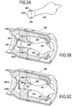
- the needle 433 is held back from the nozzle neck 421 as shown in the figure 5B in order to generate a strong thrust and adapt to the altitude level encountered in this first phase of flight.
- the keys 435 and 436 are broken, either by heat, or by a pressure force as already described above.
- the keys 435 and 436 release the upstream end 4330 of the needle 433 which then advances into the downstream part 4341b of the housing 4341 allowing the needle to be placed in the position illustrated on the figure 5C , position in which the downstream end 4331 of the needle 433 approaches the nozzle neck 421 in order to generate a reduced thrust adapted to the system needs of this second flight phase.
- FIGS. 6A and 6B illustrate another alternative embodiment of a retaining element which can be used in the gas ejection section modulation device of the invention.
- a nozzle 520 of the same type as those already described above comprises a device for modulating the gas ejection section 530 which comprises a needle 533 and a needle guide 534, the needle retaining element being here integrated into a plug 5344 closing the upstream part of the internal housing 5341 of the device 530.
- the plug 5344 comprises, on its part facing the upstream end 5330 of the needle, a rod 5345 comprising a thread 5346.
- the upstream end 5330 of the needle 533 has a recess 5335 comprising a thread 5336 capable of cooperating with the thread 5346 of the rod 5345.
- the upstream end 5330 of the needle 533 is screwed onto the rod 5345.
- the rod 5345 is made of a material capable of yielding, by softening or melting, from a determined temperature. Once this temperature is reached, the rod 5345 loses its mechanical integrity and no longer plays its role of retaining element of the upstream end 5330 of the needle 533, the thread 5346 or the rod itself breaking under the effect of temperature. Under the suction effect of the pressure forces generated in the nozzle, the needle moves (translation) then in the position illustrated on the figure 6B .
- the rod 5345 can also be dimensioned so as to break under a pressure force exerted by a pyrotechnic cartridge or by introduction of a fraction of the combustion gases as described above.
- FIGS. 7A and 7B illustrate another alternative embodiment of a retaining element which can be used in the gas ejection section modulation device of the invention.
- a nozzle 620 of the same type as those already described above comprises a device for modulating the gas ejection section 630 which comprises a needle 633 and a needle guide 634, the needle retaining element here being integrated into a plug 6344 closing the upstream part of the internal housing 6341 of the device 630. More specifically, the plug 6344 has, on its facing part from the upstream end 6330 of the needle, a rod 6345 comprising a thread 6346.
- the upstream end 6330 of the needle 633 comprises a recess 6335 comprising a thread 6336 capable of cooperating with the thread 6346 of the rod 6345. As illustrated in the figure 7A , the upstream end 6330 of the needle 633 is screwed onto the rod 6345.
- the rod 6345 has a narrowed portion 6347 which is capable of allowing the rupture of the rod 6345 under a pressure force exerted by the introduction of a fraction of the combustion gases via a valve 640 and via a conduit 641 as already described above in relation to the Figures 4A and 4B .
- the rod 6345 breaks at its narrowed part 6347.
- the rod 6347 with its narrowed part can also be made of a material capable of breaking, by softening or by fusion, from a determined temperature.
- the gas ejection section modulation device of the invention can be used in propellants, rocket motors or launchers with solid propulsion (solid propellant), liquid (liquid propellant) or hybrid (solid and liquid propellants).
Landscapes
- Engineering & Computer Science (AREA)
- Chemical & Material Sciences (AREA)
- Combustion & Propulsion (AREA)
- Mechanical Engineering (AREA)
- General Engineering & Computer Science (AREA)
- Nozzles (AREA)
Description
- La présente invention se rapporte au domaine général des propulseurs ou moteurs-fusées destinés à délivrer une poussée pour le pilotage d'engins tels que des missiles, des lanceurs ou encore des satellites, en utilisant le principe de propulsion par réaction ou par éjection de gaz. Elle vise plus précisément, mais non exclusivement, les tuyères équipant des propulseurs à propergol solide.
- Un propulseur à propergol solide est principalement constitué d'une enveloppe renfermant un bloc de propergol, d'un allumeur et d'une tuyère à divergent fixe. Le bloc de propergol est percé par un canal situé dans l'axe du propulseur qui sert de chambre de combustion. L'allumeur met le feu au propergol à une extrémité de l'enveloppe et la combustion du propergol se propage de l'avant vers l'arrière du propulseur. Le propergol brûle à une vitesse prédéfinie en produisant des gaz de combustion qui sont expulsés par la tuyère.
- La section de col de la tuyère permet de réguler la combustion du bloc de propergol de manière à maintenir la pression souhaitée dans la chambre de combustion tout en produisant la poussée attendue. Aussi, dans le cas d'un propulseur délivrant une poussée à débit unique, la section de col de la tuyère est unique et prédéterminée en fonction du niveau de poussée souhaité.
- Cependant, le recours à une section de col unique n'est pas adapté à un propulseur ayant deux régimes de fonctionnement, typiquement un fonctionnement à haut débit (accélération) et un fonctionnement à bas débit (croisière) ou à un propulseur destiné à voler à des altitudes variables.
- Pour pallier un tel inconvénient, une solution connue consiste à doter le lanceur de deux propulseurs distincts : un pour la phase d'accélération (« boost ») et un autre pour la phase de croisière. Cependant, une telle solution a comme inconvénient d'augmenter significativement le coût du lanceur.
- Il est également connu de munir une tuyère d'une section de col variable. En pratique, un pointeau mobile en translation est logé à l'intérieur de la tuyère. La position de ce pointeau dans l'écoulement des gaz de combustion permet de déterminer la section de passage des gaz qui sortent de la tuyère et ainsi d'ajuster la section d'éjection des gaz au régime de fonctionnement du propulseur.
- Cependant, les systèmes de positionnement connus associés au pointeau mobile sont des systèmes complexes, couteux et qui augmentent significativement la masse du propulseur.
- Or, il existe un besoin pour réaliser de manière économique une modulation de section d'éjection dans une tuyère de manière à optimiser le coefficient de poussée, et ce tout en minimisant l'encombrement et la masse du dispositif de modulation dans le propulseur. Le document
WO95/14163 - Ce but est atteint grâce à un dispositif de modulation de section d'éjection de gaz destiné à être placé dans une tuyère en amont du col de ladite tuyère, le dispositif de modulation comprenant :
- un pointeau s'étendant entre une extrémité amont et une extrémité aval, ladite extrémité aval ayant un diamètre décroissant formant un organe d'obturation partiel pour le col de tuyère,
- un guide de pointeau comprenant un logement interne dans lequel l'extrémité amont du pointeau est présente,
- Le dispositif de modulation de section d'éjection de gaz de l'invention propose une solution simple, à faible coût et peu encombrante permettant de définir deux modes de fonctionnement pour une tuyère, à savoir un premier mode de fonctionnement à haut débit dans lequel l'organe d'obturation partiel est en retrait axial par rapport au col de la tuyère et un second mode de fonctionnement à bas débit dans lequel l'organe d'obturation partiel est plus avancé axialement par rapport au col. Le passage du premier mode de fonctionnement au deuxième mode de fonctionnement est réalisé par rupture du ou des éléments de retenue. L'utilisation d'un ou plusieurs éléments de retenue fusibles en combinaison avec un pointeau et un guide de pointeau permet de définir une architecture économique, simple et fiable pour des tuyères à variation de section de col, et ce sans augmenter significativement la masse et l'encombrement du propulseur.
- En outre, le dispositif de modulation de section d'éjection de gaz de l'invention permet de s'affranchir de l'utilisation de deux propulseurs distincts (un propulseur pour la phase d'accélération (« boost ») et un autre propulseur pour la phase de croisière) et, par conséquent, de proposer à faible coût un système de propulsion permettant deux régimes de fonctionnement.
- Selon une première caractéristique du dispositif de modulation de section d'éjection de gaz de l'invention, le ou les éléments de retenue sont en un matériau apte à se rompre à partir d'une température déterminée.
- L'invention a également pour objet une tuyère à section de col variable comprenant un col de tuyère caractérisée en ce qu'elle comprend en outre un dispositif de modulation de section d'éjection de gaz selon l'invention, ledit dispositif de modulation étant placé dans la tuyère en amont dudit col de tuyère.
- Selon une caractéristique particulière de la tuyère de l'invention, celle-ci est de type aerospike, c'est-à-dire une tuyère fonctionnant sans divergent, ce qui diminue à la fois le coût, la masse et l'encombrement du propulseur tout en permettant d'optimiser la poussée de l'engin quelle que soit l'altitude de fonctionnement.
- L'invention a encore pour objet un propulseur comprenant une tuyère à section de col variable selon l'invention.
- Selon une caractéristique particulière du propulseur de l'invention, celui-ci comprend une enveloppe renfermant un chargement de propergol, la tuyère à section de col variable étant reliée au fond arrière de ladite enveloppe par une rallonge ou une liaison articulée.
- D'autres caractéristiques et avantages de la présente invention ressortiront de la description faite ci-dessous, en référence aux dessins annexés qui en illustrent un exemple de réalisation dépourvu de tout caractère limitatif. Sur les figures :
- les
figures 1A et 1B sont des vues schématiques en perspective et en coupe partielle d'un propulseur équipé d'une tuyère aerospike intégrant un dispositif de modulation de section d'éjection de gaz conformément à un mode de réalisation de l'invention ; - les
figures 2A et 2B sont des vues schématiques en coupe longitudinale de la tuyère desfigures 1A et 1B ; - les
figures 3A et 3B sont des vues schématiques en coupe longitudinale d'une tuyère aerospike intégrant un dispositif de modulation de section d'éjection de gaz conformément à un autre mode de réalisation de l'invention ; - les
figures 4A et 4B sont des vues schématiques en coupe longitudinale d'une tuyère aerospike intégrant un dispositif de modulation de section d'éjection de gaz conformément à un autre mode de réalisation de l'invention ; - la
figure 5A est une vue schématique en perspective montrant un pointeau utilisé dans le dispositif de modulation de section d'éjection de gaz représenté sur lesfigures 5B et 5C ; - les
figures 5B et 5C sont des vues schématiques en coupe longitudinale d'une tuyère aerospike intégrant un dispositif de modulation de section d'éjection de gaz conformément à un autre mode de réalisation de l'invention ; - les
figures 6A et 6B sont des vues schématiques en coupe longitudinale partielle d'une tuyère aerospike intégrant un dispositif de modulation de section d'éjection de gaz conformément à un autre mode de réalisation de l'invention ; - les
figures 7A et 7B sont des vues schématiques en coupe longitudinale partielle d'une tuyère aerospike intégrant un dispositif de modulation de section d'éjection de gaz conformément à un autre mode de réalisation de l'invention. - Le dispositif de modulation de section d'éjection de gaz de l'invention peut être utilisé avec tout type de tuyère, en particulier avec des tuyères comportant un divergent ou non.
- La
figure 1A illustre schématiquement en coupe longitudinale la partie arrière d'un propulseur 100 comprenant une enveloppe 110 de révolution entourant une chambre de combustion 111 dans laquelle est logé un bloc de propergol solide 112. La chambre 111 s'ouvre à travers le fond arrière 110a de l'enveloppe 110 en amont d'une tuyère 120 de type « aerospike ». Par tuyère « aerospike », on entend ici une tuyère pratiquement dépourvue de divergent et qui comprend un pointeau à profil convexe pouvant émerger au niveau de son col. Dans le mode de réalisation décrit ici, la tuyère 120 est reliée au fond arrière 110a par une rallonge 113. Toutefois, selon une variante de réalisation d'un propulseur selon l'invention, la tuyère 120 peut être également directement connectée au fond arrière de l'enveloppe du propulseur, c'est-à-dire sans la rallonge 113. Selon encore une autre variante de réalisation du propulseur selon l'invention, la tuyère peut être reliée au fond arrière de l'enveloppe du propulseur par une liaison articulée, telle qu'une rotule par exemple, de manière à permettre l'orientation de la tuyère dans plusieurs directions par rapport à l'axe de l'enveloppe du propulseur. - Conformément à l'invention, un dispositif de modulation de section d'éjection de gaz 130 est disposé à l'intérieur de la tuyère 120 du col 121 de la tuyère 120 (
figure 1B ). Dans l'exemple décrit ici, le maintien en position du dispositif de modulation 130 est assuré par deux bras 131 et 132 fixés sur la paroi interne de la tuyère 120. Les bras 131 et 132 sont disposés à 180° l'un de l'autre, le reste de l'espace circonférentielle présent autour du dispositif de modulation étant laissé libre pour permettre aux gaz issus de la chambre de combustion 111 de s'écouler vers le col de tuyère 121. Le dispositif de modulation de section d'éjection de gaz 130 comprend un pointeau 133 comprenant une tige 1333 s'étendant entre une extrémité amont 1330 et une extrémité aval 1331, ladite extrémité aval 1331 ayant un diamètre décroissant formant un organe d'obturation partiel pour le col de tuyère 121. Le dispositif de modulation 130 comprend également un guide de pointeau 134 comprenant une paroi 1342 délimitant un logement interne 1341 dans lequel l'extrémité amont 1330 du pointeau 133 est présente. Le guide de pointeau 134 comprend en outre un passage 1343 supportant la tige 1333 du pointeau et guidant ses mouvements. - Comme illustré sur les
figures 2A et 2B , l'extrémité amont 1330 du pointeau peut coulisser dans le logement interne 1341 du guide du pointeau 134 entre une première position dans laquelle ladite extrémité amont 1330 du pointeau 133 est présente dans une partie amont 1341a du logement interne 1341 (figure 2A ) et une deuxième position dans laquelle l'extrémité amont 1330 est présente dans une partie aval 1341b du logement interne 1341 (figure 2B ). - Conformément à l'invention, l'extrémité amont 1330 du pointeau 133 est maintenue dans la première position par un élément de retenue, ici une goupille 135 qui traverse à la fois l'extrémité amont 1330 du pointeau et la paroi 1342 du guide de pointeau 134. Dans le mode de réalisation décrit ici, la goupille 135 est réalisée en un matériau apte à céder, par fusion ou ramollissement, à partir d'une température déterminée. A titre d'exemples :
- pour une température de libération du pointeau déterminée autour de 85°C, la goupille 135 peut notamment être réalisée en ABS (Acrylonitrile Butadiène Styrène),
- pour une température de libération du pointeau déterminée autour de 400°C, la goupille 135 peut notamment être réalisée en aluminium,
- pour une température de libération du pointeau déterminée supérieure à 800°C, la goupille 135 peut notamment être réalisée en un alliage métallique à mémoire de forme.
- Les alliages à mémoire de forme peuvent être utilisés d'une manière générale pour réaliser le ou les éléments de retenue du dispositif de l'invention, leur composition étant déterminée en fonction de la température de libération du pointeau visée.
- Durant la première phase de vol du propulseur, dite phase d'accélération, le dispositif de modulation de section d'éjection de gaz 130 se trouve dans la configuration représentée sur la
figure 2A , configuration dans laquelle l'extrémité aval 1331 du pointeau 133 est en retrait du col de tuyère 121 afin de générer une forte poussée et s'adapter au niveau d'altitude rencontré dans cette première phase de vol. Lors de cette première phase de vol, les gaz de combustion circulant dans la tuyère 120 vont transmettre de la chaleur à la goupille 135. Une fois la température de rupture de la goupille 135 atteinte (température de fusion ou de ramolissement), celle-ci perd son intégrité mécanique et ne joue plus son rôle d'élément de retenue de l'extrémité amont 1330 du pointeau 133 qui, sous l'effet d'aspiration des efforts de pression générés dans la tuyère, se déplace (translation) dans la position illustrée sur lafigure 2B . Une première partie 135a de la goupille 135 reste alors dans l'extrémité amont 1330 du pointeau tandis qu'une deuxième partie 135b reste dans la paroi 1342 du guide de pointeau. La configuration illustrée sur lafigure 2B correspond à la deuxième phase de vol du propulseur, dite phase de croisière, configuration dans laquelle l'extrémité aval 1331 du pointeau 133 se rapproche du col de tuyère 121 afin de générer une poussée réduite adaptée aux besoins systèmes de cette deuxième phase de vol. - Dans le mode de réalisation décrit ici, la partie amont 1341a du logement interne 1341 est fermée par un bouchon 1344 réalisé en un matériau dont la conductivité thermique permet de retarder la transmission de la chaleur des gaz à la goupille et, par conséquent, l'instant auquel la goupille se rompt. Le bouchon peut être notamment réalisé en matériau composite carbone/carbone (C/C) comprenant une texture de renfort en fibres de carbone densifiée par une matrice de carbone pyrolytique (pyrocarbone), en matériau composite à matrice céramique basse densité (CMC) comprenant une texture de renfort en fibres réfractaires (carbone ou céramique) densifiée par une matrice au moins partiellement céramique ou en matériau composite à matrice organique (CMO) comprenant une texture de renfort en fibres réfractaires (carbone ou céramique) densifiée par une matrice organique (résine). Toutefois, le dispositif de modulation peut également être utilisé sans fermeture de la partie amont 1341a du logement interne 1341.
- Les
figures 3A et 3B illustrent une tuyère 220 qui comprend un dispositif de modulation de section d'éjection de gaz 230 conformément à un autre mode de réalisation de l'invention. Le dispositif de modulation 230 diffère du dispositif 130 décrit précédemment en ce que la goupille 235 qui traverse à la fois l'extrémité amont 2330 du pointeau et la paroi 2342 du guide de pointeau 234 ne cède plus sous l'effet de la chaleur mais d'un effort mécanique exercé sur l'extrémité amont 2330 du pointeau. Plus précisément, comme illustré sur lafigure 3A , l'extrémité amont 2330 du pointeau 233 comporte un épaulement 2335 en contact avec la paroi 2342 du guide de pointeau 234 délimitant le logement interne 2341 dans lequel l'extrémité amont 2330 du pointeau 233 est présente. Le dispositif de modulation de section d'éjection de gaz 230 comprend en outre un générateur de gaz, ici une cartouche pyrotechnique 240 logée dans le bras 232 du dispositif de modulation. La cartouche pyrotechnique 240 est apte à envoyer sur commande un gaz sous pression dans la partie amont 2341a du logement interne 2341 entre le fond amont 2344 dudit logement interne et l'épaulement 2335 de manière à rompre la goupille 235 et à faire coulisser l'extrémité amont 2330 du pointeau 233 vers la partie aval 2341b du logement interne 2341. La cartouche pyrotechnique 240 communique avec le logement interne 2341 via un conduit 241 ménagé dans le guide de pointeau 234 entre le bras 232 et le logement interne 2341. La goupille 235 est dimensionnée de manière à rompre sous l'effort de pression exercé par la cartouche pyrotechnique 240. La gouille 235 peut être notamment réalisée en aluminium ou en acier. - Durant la première phase de vol du propulseur, dite phase d'accélération, le dispositif de modulation de section d'éjection de gaz 230 se trouve dans la configuration représentée sur la
figure 3A , configuration dans laquelle l'extrémité aval 2331 du pointeau 233 est en retrait du col de tuyère 221 afin de générer une forte poussée et s'adapter au niveau d'altitude rencontré dans cette première phase de vol. - Une fois la première phase de vol terminée, un signal de commande est envoyé à la cartouche pyrotechnique 240 pour sa mise à feu. Sous l'effet de la pression du gaz introduit par la cartouche 240 dans la partie amont 2341a du logement interne 2341 entre le fond amont 2344 dudit logement interne et l'épaulement 2335, la goupille 235 se rompt, une première partie 235a de la goupille 235 restant alors dans l'extrémité amont 2330 du pointeau tandis qu'une deuxième partie 235b reste dans la paroi 2342 du guide de pointeau. En cédant, la goupille 235 libère l'extrémité amont 2330 du pointeau 233 qui, sous l'effet combiné des efforts de pression exercés par la cartouche pyrotechnique et des gaz circulant dans la tuyère, se déplace (translation) dans la position illustrée sur la
figure 3B . La configuration illustrée sur lafigure 3B correspond à la deuxième phase de vol du propulseur, dite phase de croisière, configuration dans laquelle l'extrémité aval 2331 du pointeau 233 se rapproche du col de tuyère 221 afin de générer une poussée réduite adaptée aux besoins systèmes de cette deuxième phase de vol. - De manière optionnelle et comme représenté sur les
figures 3A et 3B , le dispositif de modulation de section d'éjection de gaz 230 peut en outre comprendre un deuxième générateur de gaz, ici une deuxième cartouche pyrotechnique 250 qui est, dans le mode de réalisation décrit ici, logée dans l'autre bras 231 du dispositif de modulation 230. La deuxième cartouche pyrotechnique 250 est apte à envoyer sur commande un gaz sous pression dans la partie aval 2341b du logement interne 2341 entre le fond aval dudit logement interne comportant le passage 2343 supportant la tige 2333 du pointeau 233 et l'épaulement 2335. La cartouche pyrotechnique 250 communique avec le logement interne 2341 via un conduit 251 ménagé dans le guide de pointeau 234 entre le bras 232 et le logement interne 2341. Lorsqu'un signal de commande est envoyé à la cartouche pyrotechnique 250 pour sa mise à feu alors que le dispositif de modulation 230 est dans la configuration illustrée sur lafigure 3B , le pointeau 233 se déplace (translation) alors dans la position illustrée sur lafigure 3A sous l'effet de la pression introduite par la cartouche 250 entre l'épaulement 2335 et le fond aval du logement interne 2341. - Les
figures 4A et 4B illustrent une tuyère 320 qui comprend un dispositif de modulation de section d'éjection de gaz 330 conformément à un autre mode de réalisation de l'invention. Le dispositif de modulation 330 diffère du dispositif 230 décrit ci-avant en ce qu'il utilise du gaz directement issu des gaz de combustion du propulseur plutôt que des générateurs de gaz indépendants pour rompre la goupille 335 qui traverse à la fois l'extrémité amont 3330 du pointeau et la paroi 3342 du guide de pointeau 334. - Plus précisément, comme illustré sur la
figure 4A , l'extrémité amont 3330 du pointeau 333 comporte un épaulement 3335 en contact avec la paroi 3341 du guide de pointeau 334 délimitant le logement interne 3342 dans lequel l'extrémité amont 3330 du pointeau 333 est présente. Le dispositif de modulation de section d'éjection de gaz 330 comprend en outre une vanne 340 logée dans le bras 332 du dispositif de modulation. La vanne 340 est reliée à un conduit 342 qui débouche dans une partie du propulseur où une fraction des gaz de combustion peut être prélevée comme par exemple dans la chambre de combustion (non représentée sur lesfigures 4A et 4B ). La vanne 340 est apte à envoyer sur commande une fraction des gaz de combustion dans la partie amont 3341a du logement interne 3341 entre le fond amont 3344 dudit logement interne et l'épaulement 3335 de manière à rompre la goupille 335 et à faire coulisser l'extrémité amont 3330 du pointeau 333 vers la partie aval 3341b du logement interne 3341. La vanne 340 communique avec le logement interne 3341 via un conduit 341 ménagé dans le guide de pointeau 334 entre le bras 332 et le logement interne 3341. La goupille 335 est dimensionnée de manière à rompre sous l'effort de pression exercé par la fraction de gaz introduite dans le logement interne 3341 via le conduit 341. - Durant la première phase de vol du propulseur, dite phase d'accélération, le dispositif de modulation de section d'éjection de gaz 330 se trouve dans la configuration représentée sur la
figure 4A , configuration dans laquelle l'extrémité aval 3331 du pointeau 333 est en retrait du col de tuyère 321 afin de générer une forte poussée et s'adapter au niveau d'altitude rencontré dans cette première phase de vol. - Une fois la première phase de vol terminée, un signal de commande est envoyé à la vanne 340 pour son ouverture. Sous l'effet de la pression du gaz introduit par la vanne 340 dans la partie amont 3341a du logement interne 3341 entre le fond amont 3344 dudit logement interne et l'épaulement 3335, la goupille 335 se rompt, une première partie 335a de la goupille 335 restant alors dans l'extrémité amont 3330 du pointeau tandis qu'une deuxième partie 335b reste dans la paroi 3342 du guide de pointeau. En cédant, la goupille 335 libère l'extrémité amont 3330 du pointeau 333 qui, sous l'effet combiné des efforts de pression exercés par la fraction de gaz de combustion introduite dans le logement interne du guide de pointeau et des gaz circulant dans la tuyère, se déplace (translation) dans la position illustrée sur la
figure 4B . La configuration illustrée sur lafigure 4B correspond à la deuxième phase de vol du propulseur, dite phase de croisière, configuration dans laquelle l'extrémité aval 3331 du pointeau 333 se rapproche du col de tuyère 321 afin de générer une poussée réduite adaptée aux besoins systèmes de cette deuxième phase de vol. - De manière optionnelle et comme représenté sur les
figures 4A et 4B , le dispositif de modulation de section d'éjection de gaz 330 peut en outre comprendre une deuxième vanne 350 qui est dans le mode de réalisation décrit ici logée dans le deuxième bras 332 du dispositif de modulation 330. La deuxième vanne 350 est reliée à un conduit 352 qui débouche dans une partie du propulseur où une fraction des gaz de combustion peut être prélevée comme par exemple dans la chambre de combustion (non représentée sur lesfigures 4A et 4B ). La deuxième vanne 350 est apte à envoyer sur commande une fraction des gaz de combustion dans la partie aval 3341b du logement interne 3341 entre le fond aval dudit logement interne comportant le passage 3343 supportant la tige 3333 du pointeau 333 et l'épaulement 3335. - La vanne 350 communique avec le logement interne 3341 via un conduit 351 ménagé dans le guide de pointeau 334 entre le bras 332 et le logement interne 3341. Lorsqu'un signal de commande est envoyé à la vanne 350 pour son ouverture alors que le dispositif de modulation 330 est dans la configuration illustrée sur la
figure 4B , le pointeau 333 se déplace (translation) alors dans la position illustrée sur lafigure 4B sous l'effet de la pression introduite par la cartouche 350 entre l'épaulement 3335 et le fond aval du logement interne 3341. - Dans les modes de réalisation décrits ci-avant, l'élément de retenue est constitué par une goupille. Toutefois, la réalisation de l'élément de retenue dans la présente invention n'est pas limitée à une goupille et peut présenter une forme et/ou une structure différente. Selon une variante de réalisation illustrée sur les
figures 5A, 5B et 5C , un pointeau 433 comporte sur son extrémité amont 4330 deux clavettes 435 et 436 formant des éléments de retenue. Dans ce cas, le logement interne 4341 du guide de pointeau 434 du dispositif de modulation de section d'éjection de gaz 430 comprend une partie amont 4341a apte à loger l'extrémité amont 4330 du pointeau 433 avec ses deux clavettes 435 et 436 et une partie aval 4341b présentant des dimensions réduites par rapport à la partie amont 4341a de manière à définir une butée 4345 pour les clavettes 435 et 436. Ainsi, lors de la première phase de vol, le pointeau 433 est maintenu en retrait du col de tuyère 421 comme illustré sur lafigure 5B afin de générer une forte poussée et s'adapter au niveau d'altitude rencontré dans cette première phase de vol. Une fois la première phase vol terminée, les clavettes 435 et 436 sont rompues, soit par la chaleur, soit par un effort de pression comme déjà décrit ci-avant. En cédant, les clavettes 435 et 436 libèrent l'extrémité amont 4330 du pointeau 433 qui avance alors dans la partie aval 4341b du logement 4341 permettant au pointeau de se placer dans la position illustrée sur lafigure 5C , position dans laquelle l'extrémité aval 4331 du pointeau 433 se rapproche du col de tuyère 421 afin de générer une poussée réduite adaptée aux besoins systèmes de cette deuxième phase de vol. - Les
figures 6A et 6B illustrent une autre variante de réalisation d'un élément de retenue qui peut être utilisé dans le dispositif de modulation de section d'éjection de gaz de l'invention. Sur lafigure 6A , une tuyère 520 du même type que celles déjà décrites précédemment comprend un dispositif de modulation de section d'éjection de gaz 530 qui comprend un pointeau 533 et un guide de pointeau 534, l'élément de retenue du pointeau étant ici intégré à un bouchon 5344 fermant la partie amont du logement interne 5341 du dispositif 530. Plus précisément, le bouchon 5344 comporte, sur sa partie en regard de l'extrémité amont 5330 du pointeau, une tige 5345 comportant un filetage 5346. L'extrémité amont 5330 du pointeau 533 comporte un évidement 5335 comportant un taraudage 5336 apte à coopérer avec le filetage 5346 de la tige 5345. Comme illustrée sur lafigure 6A , l'extrémité amont 5330 du pointeau 533 est vissée sur la tige 5345. La tige 5345 est réalisée en un matériau apte à céder, par ramollissement ou fusion, à partir d'une température déterminée. Une fois cette température atteinte, la tige 5345 perd son intégrité mécanique et ne joue plus son rôle d'élément de retenue de l'extrémité amont 5330 du pointeau 533, le filetage 5346 ou la tige elle-même se rompant sous l'effet de la température. Sous l'effet d'aspiration des efforts de pression générés dans la tuyère, le pointeau se déplace (translation) alors dans la position illustrée sur lafigure 6B . Par ailleurs, la tige 5345 peut être également dimensionnée de manière à rompre sous un effort de pression exercé par une cartouche pyrotechnique ou par introduction d'une fraction des gaz de combustion comme décrits précédemment. - Les
figures 7A et 7B illustrent une autre variante de réalisation d'un élément de retenue qui peut être utilisé dans le dispositif de modulation de section d'éjection de gaz de l'invention. Sur lafigure 7A , une tuyère 620 du même type que celles déjà décrites précédemment comprend un dispositif de modulation de section d'éjection de gaz 630 qui comprend un pointeau 633 et un guide de pointeau 634, l'élément de retenue du pointeau étant ici intégré à un bouchon 6344 fermant la partie amont du logement interne 6341 du dispositif 630. Plus précisément, le bouchon 6344 comporte, sur sa partie en regard de l'extrémité amont 6330 du pointeau, une tige 6345 comportant un filetage 6346. L'extrémité amont 6330 du pointeau 633 comporte un évidement 6335 comportant un taraudage 6336 apte à coopérer avec le filetage 6346 de la tige 6345. Comme illustrée sur lafigure 7A , l'extrémité amont 6330 du pointeau 633 est vissée sur la tige 6345. - La tige 6345 comporte une partie rétrécie 6347 qui est apte à permettre la rupture de la tige 6345 sous un effort de pression exercé par l'introduction d'une fraction des gaz de combustion par l'intermédiaire d'une vanne 640 et via un conduit 641 comme déjà décrit ci-avant en relation avec les
figures 4A et 4B . Une fois la fraction de gaz introduite dans la partie amont 6341a du logement interne 6341 entre le bouchon 6344 et l'épaulement 6356, la tige 6345 se rompt au niveau de sa partie rétrécie 6347. Sous l'effet combiné des efforts de pression exercés par la fraction de gaz de combustion introduite dans le logement interne du guide de pointeau et des gaz circulant dans la tuyère, le pointeau se déplace (translation) alors dans la position illustrée sur lafigure 7B . La tige 6347 avec sa partie rétrécie peut être également réalisée en un matériau apte à se rompre, par ramollissement ou par fusion, à partir d'une température déterminée. - Le dispositif de modulation de section d'éjection de gaz de l'invention peut être utilisé dans des propulseurs, moteurs-fusées ou lanceurs à propulsion solide (propergol solide), liquide (propergol liquide) ou hybride (propergols solide et liquide).
Claims (6)
- Dispositif de modulation de section d'éjection de gaz (130) destiné à être placé dans une tuyère (120) en amont du col (121) de ladite tuyère, le dispositif de modulation comprenant :- un pointeau (133) s'étendant entre une extrémité amont (1330) et une extrémité aval (1331), ladite extrémité aval ayant un diamètre décroissant formant un organe d'obturation partiel pour le col de tuyère (121),- un guide de pointeau (134) comprenant un logement interne (1341) dans lequel l'extrémité amont (1330) du pointeau (133) est présente,l'extrémité amont (1330) dudit pointeau étant apte à coulisser dans le logement interne (1341) du guide du pointeau (132) entre une première position dans laquelle ladite extrémité amont du pointeau est présente dans une partie amont (1341a) du logement interne (1341) et une deuxième position dans laquelle ladite extrémité amont est présente dans une partie aval (1341b) du logement interne (1341), le dispositif étant caractérise en ce que l'extrémité amont (1330) dudit pointeau (133) est maintenue dans la première position par au moins un élément de retenue (135) apte à se rompre sous l'effet de la chaleur, l'élément de retenue correspondant à une goupille traversant à la fois l'extrémité amont du pointeau et la paroi du guide de pointeau.
- Dispositif selon la revendication 1, caractérisé en ce que le ou les éléments de retenue (135) sont en un matériau apte à se rompre à partir d'une température déterminée.
- Tuyère (120) à section de col variable comprenant un col de tuyère (121) caractérisée en ce qu'elle comprend en outre un dispositif de modulation de section d'éjection de gaz (130) selon la revendication 1 ou 2, ledit dispositif de modulation étant placé dans la tuyère en amont dudit col de tuyère.
- Tuyère selon la revendication 3, caractérisée en ce qu'elle est de type aerospike.
- Propulseur comprenant une tuyère à section de col variable selon la revendication 3 ou 4.
- Propulseur (100) selon la revendication 5, caractérisé en ce qu'il comprend une enveloppe (110) renfermant un chargement de propergol (112), la tuyère (120) à section de col variable étant reliée au fond arrière (110a) de ladite enveloppe (110) par une rallonge (113) ou une liaison articulée.
Applications Claiming Priority (2)
| Application Number | Priority Date | Filing Date | Title |
|---|---|---|---|
| FR1402886A FR3030634B1 (fr) | 2014-12-17 | 2014-12-17 | Dispositif de modulation de section d'ejection de gaz |
| PCT/FR2015/053542 WO2016097602A1 (fr) | 2014-12-17 | 2015-12-16 | Dispositif de modulation de section d'ejection de gaz |
Publications (2)
| Publication Number | Publication Date |
|---|---|
| EP3234332A1 EP3234332A1 (fr) | 2017-10-25 |
| EP3234332B1 true EP3234332B1 (fr) | 2020-04-15 |
Family
ID=53177515
Family Applications (1)
| Application Number | Title | Priority Date | Filing Date |
|---|---|---|---|
| EP15820230.9A Active EP3234332B1 (fr) | 2014-12-17 | 2015-12-16 | Dispositif de modulation de section d'éjection de gaz |
Country Status (7)
| Country | Link |
|---|---|
| US (1) | US10690090B2 (fr) |
| EP (1) | EP3234332B1 (fr) |
| JP (1) | JP6666350B2 (fr) |
| KR (1) | KR102412566B1 (fr) |
| FR (1) | FR3030634B1 (fr) |
| IL (1) | IL252813B (fr) |
| WO (1) | WO2016097602A1 (fr) |
Families Citing this family (2)
| Publication number | Priority date | Publication date | Assignee | Title |
|---|---|---|---|---|
| FR3038936B1 (fr) | 2015-07-17 | 2020-02-07 | Arianegroup Sas | Dispositif de modulation de section d'ejection de gaz |
| CN111811739B (zh) * | 2020-09-04 | 2021-03-02 | 航天科工火箭技术有限公司 | 一种液体火箭发动机推力室气密工装及其试验方法 |
Family Cites Families (12)
| Publication number | Priority date | Publication date | Assignee | Title |
|---|---|---|---|---|
| US3230704A (en) * | 1961-10-30 | 1966-01-25 | Thiokol Chemical Corp | Rocket engine |
| US3329089A (en) | 1964-12-24 | 1967-07-04 | Herbert L Harrison | Retention-release mechanism for reaction motors and rocket interstages |
| US3567942A (en) * | 1967-04-27 | 1971-03-02 | Industrial Nucleonics Corp | Nucleonic measuring apparatus with automatic fire safety radiation source shutter closing and locking means controlled by a fusible element which melts at high temperatures |
| JPS5034839B1 (fr) | 1968-08-27 | 1975-11-11 | ||
| US4495763A (en) * | 1983-03-21 | 1985-01-29 | Thiokol Corporation | Dual-thrust nozzle apparatus for rockets |
| US5044154A (en) * | 1989-11-27 | 1991-09-03 | Thiokol Corporation | Safety mechanism for rendering a rocket motor non-propulsive |
| US5435128A (en) * | 1993-11-15 | 1995-07-25 | Thiokol Corporation | Pyrotechnically driven nozzle restrictor |
| US5491973A (en) * | 1994-10-17 | 1996-02-20 | Aerojet General Corporation | Self-actuating control for rocket motor nozzle |
| GB9513561D0 (en) | 1995-07-04 | 1995-09-06 | Royal Ordnance Plc | Improvements in or relating to motors |
| US7565797B2 (en) * | 2004-02-27 | 2009-07-28 | Ghkn Engineering Llc | Systems and methods for varying the thrust of rocket motors and engines while maintaining higher efficiency using moveable plug nozzles |
| FR3002982B1 (fr) | 2013-03-07 | 2015-04-10 | Herakles | Dispositif de modulation de section d'ejection de gaz. |
| KR101372858B1 (ko) * | 2013-09-12 | 2014-03-10 | 국방과학연구소 | 이중추력 추진기관의 노즐목 조절장치 |
-
2014
- 2014-12-17 FR FR1402886A patent/FR3030634B1/fr active Active
-
2015
- 2015-12-16 US US15/536,448 patent/US10690090B2/en active Active
- 2015-12-16 KR KR1020177019920A patent/KR102412566B1/ko active IP Right Grant
- 2015-12-16 JP JP2017532795A patent/JP6666350B2/ja active Active
- 2015-12-16 WO PCT/FR2015/053542 patent/WO2016097602A1/fr active Application Filing
- 2015-12-16 EP EP15820230.9A patent/EP3234332B1/fr active Active
-
2017
- 2017-06-11 IL IL252813A patent/IL252813B/en unknown
Non-Patent Citations (1)
| Title |
|---|
| None * |
Also Published As
| Publication number | Publication date |
|---|---|
| US20170350350A1 (en) | 2017-12-07 |
| FR3030634B1 (fr) | 2021-09-24 |
| IL252813B (en) | 2022-04-01 |
| JP2018503767A (ja) | 2018-02-08 |
| KR20170100566A (ko) | 2017-09-04 |
| JP6666350B2 (ja) | 2020-03-13 |
| KR102412566B1 (ko) | 2022-06-23 |
| US10690090B2 (en) | 2020-06-23 |
| EP3234332A1 (fr) | 2017-10-25 |
| FR3030634A1 (fr) | 2016-06-24 |
| WO2016097602A1 (fr) | 2016-06-23 |
| IL252813A0 (en) | 2017-08-31 |
Similar Documents
| Publication | Publication Date | Title |
|---|---|---|
| EP2143927B1 (fr) | Moteur-fusée à propergol liquide avec obturateur de chambre propulsive | |
| EP2964946B1 (fr) | Tuyere a section de col variable de propulseur d'engin aerospatial munie d'un pointeau mobile | |
| EP3234332B1 (fr) | Dispositif de modulation de section d'éjection de gaz | |
| EP3325795B1 (fr) | Dispositif de modulation de section d'éjection de gaz | |
| EP2964947B1 (fr) | Dispositif de modulation de section d'ejection de gaz | |
| EP1101030B1 (fr) | Tuyere compacte et modulable pour le pilotage d'engins aerospatiaux | |
| EP2226605B1 (fr) | Dispositif de pilotage d'un missile ou d'un projectile | |
| FR2731471A1 (fr) | Moteur-fusee a propergol solide avec charges propulsives a combustion exterieure et a combustion interieure | |
| EP1541833B1 (fr) | Générateur de gaz et turboréacteur équipé d'un tel générateur pour le démarrage | |
| EP0211703B1 (fr) | Dispositif de fermeture temporaire d'un orifice interne d'un propulseur | |
| EP2153162B1 (fr) | Chaine pyrotechnique d'allumage d'une charge principale de propulsion d'un missile | |
| EP2623918B1 (fr) | Dispositif de lancement pneumatique | |
| EP3891375B1 (fr) | Propulseur solide pour lanceur | |
| EP3368420B1 (fr) | Systéme de pilotage en force et de contrôle d'attitude a compacité augmentée et engin comportant un tel système | |
| FR2776372A1 (fr) | Obus perforant anti structures betonnees et dispositif de conversion permettant d'obtenir un tel obus perforant a partir d'un obus explosif | |
| EP2913628A1 (fr) | Fusée d'ogive de projectile d'artillerie comportant un dispositif de freinage en translation | |
| EP0614006A1 (fr) | Système d'injection intermittente des propergols | |
| EP0611196A1 (fr) | Munitions pour canons, mortiers et similaires à énergie de recul limitée |
Legal Events
| Date | Code | Title | Description |
|---|---|---|---|
| STAA | Information on the status of an ep patent application or granted ep patent |
Free format text: STATUS: THE INTERNATIONAL PUBLICATION HAS BEEN MADE |
|
| PUAI | Public reference made under article 153(3) epc to a published international application that has entered the european phase |
Free format text: ORIGINAL CODE: 0009012 |
|
| STAA | Information on the status of an ep patent application or granted ep patent |
Free format text: STATUS: REQUEST FOR EXAMINATION WAS MADE |
|
| 17P | Request for examination filed |
Effective date: 20170630 |
|
| AK | Designated contracting states |
Kind code of ref document: A1 Designated state(s): AL AT BE BG CH CY CZ DE DK EE ES FI FR GB GR HR HU IE IS IT LI LT LU LV MC MK MT NL NO PL PT RO RS SE SI SK SM TR |
|
| AX | Request for extension of the european patent |
Extension state: BA ME |
|
| RIN1 | Information on inventor provided before grant (corrected) |
Inventor name: CAUBET, PASCAL Inventor name: LARRIEU, JEAN-MICHEL Inventor name: RIPOL, PIERRE |
|
| RAP1 | Party data changed (applicant data changed or rights of an application transferred) |
Owner name: ARIANEGROUP SAS |
|
| DAV | Request for validation of the european patent (deleted) | ||
| DAX | Request for extension of the european patent (deleted) | ||
| STAA | Information on the status of an ep patent application or granted ep patent |
Free format text: STATUS: EXAMINATION IS IN PROGRESS |
|
| 17Q | First examination report despatched |
Effective date: 20190517 |
|
| GRAP | Despatch of communication of intention to grant a patent |
Free format text: ORIGINAL CODE: EPIDOSNIGR1 |
|
| STAA | Information on the status of an ep patent application or granted ep patent |
Free format text: STATUS: GRANT OF PATENT IS INTENDED |
|
| INTG | Intention to grant announced |
Effective date: 20191106 |
|
| GRAS | Grant fee paid |
Free format text: ORIGINAL CODE: EPIDOSNIGR3 |
|
| GRAA | (expected) grant |
Free format text: ORIGINAL CODE: 0009210 |
|
| STAA | Information on the status of an ep patent application or granted ep patent |
Free format text: STATUS: THE PATENT HAS BEEN GRANTED |
|
| AK | Designated contracting states |
Kind code of ref document: B1 Designated state(s): AL AT BE BG CH CY CZ DE DK EE ES FI FR GB GR HR HU IE IS IT LI LT LU LV MC MK MT NL NO PL PT RO RS SE SI SK SM TR |
|
| REG | Reference to a national code |
Ref country code: CH Ref legal event code: EP |
|
| REG | Reference to a national code |
Ref country code: DE Ref legal event code: R096 Ref document number: 602015050839 Country of ref document: DE |
|
| REG | Reference to a national code |
Ref country code: IE Ref legal event code: FG4D Free format text: LANGUAGE OF EP DOCUMENT: FRENCH |
|
| REG | Reference to a national code |
Ref country code: AT Ref legal event code: REF Ref document number: 1257578 Country of ref document: AT Kind code of ref document: T Effective date: 20200515 |
|
| REG | Reference to a national code |
Ref country code: NL Ref legal event code: MP Effective date: 20200415 |
|
| REG | Reference to a national code |
Ref country code: LT Ref legal event code: MG4D |
|
| PG25 | Lapsed in a contracting state [announced via postgrant information from national office to epo] |
Ref country code: NL Free format text: LAPSE BECAUSE OF FAILURE TO SUBMIT A TRANSLATION OF THE DESCRIPTION OR TO PAY THE FEE WITHIN THE PRESCRIBED TIME-LIMIT Effective date: 20200415 Ref country code: PT Free format text: LAPSE BECAUSE OF FAILURE TO SUBMIT A TRANSLATION OF THE DESCRIPTION OR TO PAY THE FEE WITHIN THE PRESCRIBED TIME-LIMIT Effective date: 20200817 Ref country code: LT Free format text: LAPSE BECAUSE OF FAILURE TO SUBMIT A TRANSLATION OF THE DESCRIPTION OR TO PAY THE FEE WITHIN THE PRESCRIBED TIME-LIMIT Effective date: 20200415 Ref country code: SE Free format text: LAPSE BECAUSE OF FAILURE TO SUBMIT A TRANSLATION OF THE DESCRIPTION OR TO PAY THE FEE WITHIN THE PRESCRIBED TIME-LIMIT Effective date: 20200415 Ref country code: NO Free format text: LAPSE BECAUSE OF FAILURE TO SUBMIT A TRANSLATION OF THE DESCRIPTION OR TO PAY THE FEE WITHIN THE PRESCRIBED TIME-LIMIT Effective date: 20200715 Ref country code: GR Free format text: LAPSE BECAUSE OF FAILURE TO SUBMIT A TRANSLATION OF THE DESCRIPTION OR TO PAY THE FEE WITHIN THE PRESCRIBED TIME-LIMIT Effective date: 20200716 Ref country code: FI Free format text: LAPSE BECAUSE OF FAILURE TO SUBMIT A TRANSLATION OF THE DESCRIPTION OR TO PAY THE FEE WITHIN THE PRESCRIBED TIME-LIMIT Effective date: 20200415 Ref country code: IS Free format text: LAPSE BECAUSE OF FAILURE TO SUBMIT A TRANSLATION OF THE DESCRIPTION OR TO PAY THE FEE WITHIN THE PRESCRIBED TIME-LIMIT Effective date: 20200815 |
|
| REG | Reference to a national code |
Ref country code: AT Ref legal event code: MK05 Ref document number: 1257578 Country of ref document: AT Kind code of ref document: T Effective date: 20200415 |
|
| PG25 | Lapsed in a contracting state [announced via postgrant information from national office to epo] |
Ref country code: RS Free format text: LAPSE BECAUSE OF FAILURE TO SUBMIT A TRANSLATION OF THE DESCRIPTION OR TO PAY THE FEE WITHIN THE PRESCRIBED TIME-LIMIT Effective date: 20200415 Ref country code: LV Free format text: LAPSE BECAUSE OF FAILURE TO SUBMIT A TRANSLATION OF THE DESCRIPTION OR TO PAY THE FEE WITHIN THE PRESCRIBED TIME-LIMIT Effective date: 20200415 Ref country code: HR Free format text: LAPSE BECAUSE OF FAILURE TO SUBMIT A TRANSLATION OF THE DESCRIPTION OR TO PAY THE FEE WITHIN THE PRESCRIBED TIME-LIMIT Effective date: 20200415 Ref country code: BG Free format text: LAPSE BECAUSE OF FAILURE TO SUBMIT A TRANSLATION OF THE DESCRIPTION OR TO PAY THE FEE WITHIN THE PRESCRIBED TIME-LIMIT Effective date: 20200715 |
|
| PG25 | Lapsed in a contracting state [announced via postgrant information from national office to epo] |
Ref country code: AL Free format text: LAPSE BECAUSE OF FAILURE TO SUBMIT A TRANSLATION OF THE DESCRIPTION OR TO PAY THE FEE WITHIN THE PRESCRIBED TIME-LIMIT Effective date: 20200415 |
|
| REG | Reference to a national code |
Ref country code: DE Ref legal event code: R097 Ref document number: 602015050839 Country of ref document: DE |
|
| PG25 | Lapsed in a contracting state [announced via postgrant information from national office to epo] |
Ref country code: EE Free format text: LAPSE BECAUSE OF FAILURE TO SUBMIT A TRANSLATION OF THE DESCRIPTION OR TO PAY THE FEE WITHIN THE PRESCRIBED TIME-LIMIT Effective date: 20200415 Ref country code: SM Free format text: LAPSE BECAUSE OF FAILURE TO SUBMIT A TRANSLATION OF THE DESCRIPTION OR TO PAY THE FEE WITHIN THE PRESCRIBED TIME-LIMIT Effective date: 20200415 Ref country code: RO Free format text: LAPSE BECAUSE OF FAILURE TO SUBMIT A TRANSLATION OF THE DESCRIPTION OR TO PAY THE FEE WITHIN THE PRESCRIBED TIME-LIMIT Effective date: 20200415 Ref country code: CZ Free format text: LAPSE BECAUSE OF FAILURE TO SUBMIT A TRANSLATION OF THE DESCRIPTION OR TO PAY THE FEE WITHIN THE PRESCRIBED TIME-LIMIT Effective date: 20200415 Ref country code: ES Free format text: LAPSE BECAUSE OF FAILURE TO SUBMIT A TRANSLATION OF THE DESCRIPTION OR TO PAY THE FEE WITHIN THE PRESCRIBED TIME-LIMIT Effective date: 20200415 Ref country code: AT Free format text: LAPSE BECAUSE OF FAILURE TO SUBMIT A TRANSLATION OF THE DESCRIPTION OR TO PAY THE FEE WITHIN THE PRESCRIBED TIME-LIMIT Effective date: 20200415 Ref country code: DK Free format text: LAPSE BECAUSE OF FAILURE TO SUBMIT A TRANSLATION OF THE DESCRIPTION OR TO PAY THE FEE WITHIN THE PRESCRIBED TIME-LIMIT Effective date: 20200415 |
|
| PLBE | No opposition filed within time limit |
Free format text: ORIGINAL CODE: 0009261 |
|
| STAA | Information on the status of an ep patent application or granted ep patent |
Free format text: STATUS: NO OPPOSITION FILED WITHIN TIME LIMIT |
|
| PG25 | Lapsed in a contracting state [announced via postgrant information from national office to epo] |
Ref country code: SK Free format text: LAPSE BECAUSE OF FAILURE TO SUBMIT A TRANSLATION OF THE DESCRIPTION OR TO PAY THE FEE WITHIN THE PRESCRIBED TIME-LIMIT Effective date: 20200415 Ref country code: PL Free format text: LAPSE BECAUSE OF FAILURE TO SUBMIT A TRANSLATION OF THE DESCRIPTION OR TO PAY THE FEE WITHIN THE PRESCRIBED TIME-LIMIT Effective date: 20200415 |
|
| 26N | No opposition filed |
Effective date: 20210118 |
|
| PG25 | Lapsed in a contracting state [announced via postgrant information from national office to epo] |
Ref country code: SI Free format text: LAPSE BECAUSE OF FAILURE TO SUBMIT A TRANSLATION OF THE DESCRIPTION OR TO PAY THE FEE WITHIN THE PRESCRIBED TIME-LIMIT Effective date: 20200415 |
|
| REG | Reference to a national code |
Ref country code: CH Ref legal event code: PL |
|
| PG25 | Lapsed in a contracting state [announced via postgrant information from national office to epo] |
Ref country code: MC Free format text: LAPSE BECAUSE OF FAILURE TO SUBMIT A TRANSLATION OF THE DESCRIPTION OR TO PAY THE FEE WITHIN THE PRESCRIBED TIME-LIMIT Effective date: 20200415 |
|
| REG | Reference to a national code |
Ref country code: BE Ref legal event code: MM Effective date: 20201231 |
|
| PG25 | Lapsed in a contracting state [announced via postgrant information from national office to epo] |
Ref country code: LU Free format text: LAPSE BECAUSE OF NON-PAYMENT OF DUE FEES Effective date: 20201216 Ref country code: IE Free format text: LAPSE BECAUSE OF NON-PAYMENT OF DUE FEES Effective date: 20201216 |
|
| PG25 | Lapsed in a contracting state [announced via postgrant information from national office to epo] |
Ref country code: LI Free format text: LAPSE BECAUSE OF NON-PAYMENT OF DUE FEES Effective date: 20201231 Ref country code: CH Free format text: LAPSE BECAUSE OF NON-PAYMENT OF DUE FEES Effective date: 20201231 |
|
| PG25 | Lapsed in a contracting state [announced via postgrant information from national office to epo] |
Ref country code: TR Free format text: LAPSE BECAUSE OF FAILURE TO SUBMIT A TRANSLATION OF THE DESCRIPTION OR TO PAY THE FEE WITHIN THE PRESCRIBED TIME-LIMIT Effective date: 20200415 Ref country code: MT Free format text: LAPSE BECAUSE OF FAILURE TO SUBMIT A TRANSLATION OF THE DESCRIPTION OR TO PAY THE FEE WITHIN THE PRESCRIBED TIME-LIMIT Effective date: 20200415 Ref country code: CY Free format text: LAPSE BECAUSE OF FAILURE TO SUBMIT A TRANSLATION OF THE DESCRIPTION OR TO PAY THE FEE WITHIN THE PRESCRIBED TIME-LIMIT Effective date: 20200415 |
|
| PG25 | Lapsed in a contracting state [announced via postgrant information from national office to epo] |
Ref country code: MK Free format text: LAPSE BECAUSE OF FAILURE TO SUBMIT A TRANSLATION OF THE DESCRIPTION OR TO PAY THE FEE WITHIN THE PRESCRIBED TIME-LIMIT Effective date: 20200415 |
|
| PG25 | Lapsed in a contracting state [announced via postgrant information from national office to epo] |
Ref country code: BE Free format text: LAPSE BECAUSE OF NON-PAYMENT OF DUE FEES Effective date: 20201231 |
|
| REG | Reference to a national code |
Ref country code: DE Ref legal event code: R082 Ref document number: 602015050839 Country of ref document: DE Representative=s name: CBDL PATENTANWAELTE GBR, DE |
|
| P01 | Opt-out of the competence of the unified patent court (upc) registered |
Effective date: 20230612 |
|
| PGFP | Annual fee paid to national office [announced via postgrant information from national office to epo] |
Ref country code: GB Payment date: 20231220 Year of fee payment: 9 |
|
| PGFP | Annual fee paid to national office [announced via postgrant information from national office to epo] |
Ref country code: IT Payment date: 20231228 Year of fee payment: 9 Ref country code: FR Payment date: 20231221 Year of fee payment: 9 Ref country code: DE Payment date: 20231214 Year of fee payment: 9 |