EP3233739B1 - Schlammbehandlungsvorrichtung und -verfahren - Google Patents
Schlammbehandlungsvorrichtung und -verfahren Download PDFInfo
- Publication number
- EP3233739B1 EP3233739B1 EP15832808.8A EP15832808A EP3233739B1 EP 3233739 B1 EP3233739 B1 EP 3233739B1 EP 15832808 A EP15832808 A EP 15832808A EP 3233739 B1 EP3233739 B1 EP 3233739B1
- Authority
- EP
- European Patent Office
- Prior art keywords
- sludge
- zone
- screws
- powder additive
- less
- Prior art date
- Legal status (The legal status is an assumption and is not a legal conclusion. Google has not performed a legal analysis and makes no representation as to the accuracy of the status listed.)
- Not-in-force
Links
- 239000010802 sludge Substances 0.000 title claims description 93
- 238000000034 method Methods 0.000 title claims description 27
- 239000000654 additive Substances 0.000 claims description 59
- 230000000996 additive effect Effects 0.000 claims description 59
- 239000000843 powder Substances 0.000 claims description 33
- 239000000203 mixture Substances 0.000 claims description 26
- 235000008733 Citrus aurantifolia Nutrition 0.000 claims description 25
- 235000011941 Tilia x europaea Nutrition 0.000 claims description 25
- 239000004571 lime Substances 0.000 claims description 25
- 238000002156 mixing Methods 0.000 claims description 13
- 238000011144 upstream manufacturing Methods 0.000 claims description 7
- 238000001125 extrusion Methods 0.000 claims description 3
- 238000011084 recovery Methods 0.000 claims description 2
- 230000008569 process Effects 0.000 description 13
- ODINCKMPIJJUCX-UHFFFAOYSA-N Calcium oxide Chemical compound [Ca]=O ODINCKMPIJJUCX-UHFFFAOYSA-N 0.000 description 11
- 230000032258 transport Effects 0.000 description 11
- 239000000463 material Substances 0.000 description 9
- 235000012255 calcium oxide Nutrition 0.000 description 5
- 239000000292 calcium oxide Substances 0.000 description 5
- 230000001105 regulatory effect Effects 0.000 description 5
- XLYOFNOQVPJJNP-UHFFFAOYSA-N water Substances O XLYOFNOQVPJJNP-UHFFFAOYSA-N 0.000 description 5
- AXCZMVOFGPJBDE-UHFFFAOYSA-L calcium dihydroxide Chemical compound [OH-].[OH-].[Ca+2] AXCZMVOFGPJBDE-UHFFFAOYSA-L 0.000 description 4
- 235000021183 entrée Nutrition 0.000 description 4
- 238000009825 accumulation Methods 0.000 description 3
- 239000000920 calcium hydroxide Substances 0.000 description 3
- 235000011116 calcium hydroxide Nutrition 0.000 description 3
- 229910001861 calcium hydroxide Inorganic materials 0.000 description 3
- 238000006243 chemical reaction Methods 0.000 description 3
- 238000001935 peptisation Methods 0.000 description 3
- 239000002002 slurry Substances 0.000 description 3
- 230000015572 biosynthetic process Effects 0.000 description 2
- 230000001276 controlling effect Effects 0.000 description 2
- 238000000855 fermentation Methods 0.000 description 2
- 239000010801 sewage sludge Substances 0.000 description 2
- 239000007787 solid Substances 0.000 description 2
- 238000004065 wastewater treatment Methods 0.000 description 2
- 230000009471 action Effects 0.000 description 1
- 230000009418 agronomic effect Effects 0.000 description 1
- 238000003556 assay Methods 0.000 description 1
- 230000008901 benefit Effects 0.000 description 1
- 230000006378 damage Effects 0.000 description 1
- 230000018044 dehydration Effects 0.000 description 1
- 238000006297 dehydration reaction Methods 0.000 description 1
- 239000006185 dispersion Substances 0.000 description 1
- 230000009977 dual effect Effects 0.000 description 1
- 230000000694 effects Effects 0.000 description 1
- 235000021050 feed intake Nutrition 0.000 description 1
- 230000004151 fermentation Effects 0.000 description 1
- 238000011049 filling Methods 0.000 description 1
- 239000008394 flocculating agent Substances 0.000 description 1
- 230000036541 health Effects 0.000 description 1
- 238000010438 heat treatment Methods 0.000 description 1
- 239000008241 heterogeneous mixture Substances 0.000 description 1
- 230000006872 improvement Effects 0.000 description 1
- 230000007774 longterm Effects 0.000 description 1
- 238000012423 maintenance Methods 0.000 description 1
- 238000000691 measurement method Methods 0.000 description 1
- 244000005700 microbiome Species 0.000 description 1
- 238000006386 neutralization reaction Methods 0.000 description 1
- 235000019645 odor Nutrition 0.000 description 1
- 238000012856 packing Methods 0.000 description 1
- 239000002245 particle Substances 0.000 description 1
- 244000052769 pathogen Species 0.000 description 1
- 239000004033 plastic Substances 0.000 description 1
- 229920003023 plastic Polymers 0.000 description 1
- 238000012545 processing Methods 0.000 description 1
- 230000009467 reduction Effects 0.000 description 1
- 238000005728 strengthening Methods 0.000 description 1
- 238000012360 testing method Methods 0.000 description 1
- 235000013619 trace mineral Nutrition 0.000 description 1
- 239000011573 trace mineral Substances 0.000 description 1
- 230000009466 transformation Effects 0.000 description 1
Images


Classifications
-
- C—CHEMISTRY; METALLURGY
- C02—TREATMENT OF WATER, WASTE WATER, SEWAGE, OR SLUDGE
- C02F—TREATMENT OF WATER, WASTE WATER, SEWAGE, OR SLUDGE
- C02F11/00—Treatment of sludge; Devices therefor
- C02F11/12—Treatment of sludge; Devices therefor by de-watering, drying or thickening
- C02F11/14—Treatment of sludge; Devices therefor by de-watering, drying or thickening with addition of chemical agents
- C02F11/143—Treatment of sludge; Devices therefor by de-watering, drying or thickening with addition of chemical agents using inorganic substances
- C02F11/145—Treatment of sludge; Devices therefor by de-watering, drying or thickening with addition of chemical agents using inorganic substances using calcium compounds
-
- C—CHEMISTRY; METALLURGY
- C02—TREATMENT OF WATER, WASTE WATER, SEWAGE, OR SLUDGE
- C02F—TREATMENT OF WATER, WASTE WATER, SEWAGE, OR SLUDGE
- C02F2209/00—Controlling or monitoring parameters in water treatment
Definitions
- the present invention relates to a device and a method for the treatment of sludge with a powder additive, such as in particular lime, in a corotating twin-screw extruder having a length / diameter ratio of less than 20 and comprising a means servo-control device for regulating the supply flow rate of powder additive as a function of the sludge feed rate.
- a powder additive such as in particular lime
- the device and method of the present invention are particularly applicable to sewage sludge after dehydration thereof.
- quicklime reacts with the water contained in the sludge, which has the effect, on the one hand to increase the temperature because the reaction is exothermic, and on the other hand to reduce the water content by transformation of the sludge.
- quick lime in slaked lime
- a sludge is hygienized when its pH remains higher than 12 during the entire storage period and the reaction temperature has been higher than 55 ° C for 75 minutes or any other equivalent time / temperature pair (such than 58 ° C for 5 minutes).
- the mixture of lime and mud is carried out with relatively hardy tools, either with mono-screws, or with bladed or plow-specific mixers, and the end result is often coarse, with a highly heterogeneous mixture .
- This heterogeneity of the mixture implies a heterogeneity of the action of lime on the pathogenic organisms: at low doses, the pH is not uniformly equal to 12 and fermentation recoveries are often observed. Also, to comply with the legislation, overdose is common.
- the Applicant has described in the French patent FR 2 940 800 , a sludge treatment process in a corotative twin-screw extruder.
- the device used in this process was not suitable for use in a treatment plant. It is indeed desirable that the device have small dimensions and that it is mobile in order to meet the specific needs of small facilities, such as rural wastewater treatment plants.
- the present inventors have found that a corotative twin-screw extruder having a length / diameter ratio of less than 20 ensures a high quality blend while having reduced dimensions.
- device developed by the present inventors makes it possible to limit the quantity of pulverulent additive used to treat the sludge by virtue of the mode of introduction of said pulverulent additive into the device and to the control of its flow rate as a function of the flow rate and the quality of the mud to be treated.
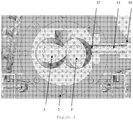
- the device (1) of the present invention comprises a sheath (2) corotating double screw.
- the screws (3, 3 ') of said sheath (2) are fully interpenetrated corotative screws.
- the screws (3, 3 ') of the device according to the invention each have a length / diameter ratio of less than 20, preferably less than 14, more preferably less than 10, the length corresponding to the total length of the screw, expressed in mm, and the diameter corresponding to the nominal diameter of the screw, expressed in mm.
- This length / specific diameter ratio makes it possible to obtain a mixture of sludge and homogeneous powdery additive while optimizing the dimensioning of the device.
- each zone comprises two segments of screws (3, 3 ').
- the two or three zones can be assembled and disassembled easily. This makes it possible to limit maintenance costs when renewing the key parts of the mixing member.
- each zone may consist of one or more modules that are nested on a shaft, for example a shaft provided with splines which advantageously allow the modules to be secured to the shaft.
- the first zone (4) ensures the mixing of the sludge and the powdery additive and the transport of said mixture to the second zone (5).
- the second zone (5) transports the mixture of sludge and powdery additive to the exit of the sheath.
- the device of the invention may optionally comprise a third zone (4a) located upstream of the first zone. Said third zone (4a) for transporting the sludge from the sludge feed inlet (6) to the first zone (4).
- the function of the zone is determined by the geometry of the screw segments (3, 3 ') of each zone. Indeed, an area in which the threads of the two screws are in the direct direction, that is to say that the direction of advancement of the threads is the same as the direction of rotation of the screws, allows the material to be transported.
- the pitch of the net determines the speed of transport: the greater the pitch, the greater the speed of transport.
- the screw segments (3, 3 ') of the second zone (5) and of the optional third zone (4a) of the device (1) according to the invention have threads in the forward direction while the screw segments (3, 3 ') of the first zone (4) have nets in the indirect direction.
- the first zone (4) comprises two modules, each module comprising 4 bilobia, each bilobe being shifted by -30 ° relative to the bilobe which precedes it.
- the second zone (5) comprises two modules and possibly a die.
- the first module can in particular present a rapid step so to avoid the accumulation of material after the mixing zone.
- the second module may in particular have a slow step in order to slow the material before the exit of the device and thus achieve a filling rate of the maximum extruder.
- the rapid step and the slow step can in particular be as defined above.
- the die may in particular make it possible to shape the material leaving the device according to the invention.
- the optional third zone (4a) may comprise one, two or three modules.
- the modules may in particular have a rapid step to prevent the accumulation of material in the device or a slow step.
- the rapid step may in particular be a pitch of between 100 and 200 mm, in particular between 125 and 175 mm, more particularly between 140 and 160 mm.
- the slow pitch may in particular be a pitch of between 10 and 70 mm, in particular between 20 and 60 mm, more particularly between 30 and 50 mm.
- the device (1) according to the invention also comprises a sludge feed inlet (6) opening upstream of the first zone (4) or of the possible third zone (4a) and a feed inlet.
- pulverulent additive (7) opening at the level of the first zone (4) or the possible third zone (4a).
- the mixture of sludge and powdery additive is removed from the device (1) by an outlet (8) located downstream of the second zone (5).
- the sludge feed inlet (6) may comprise a sludge feed device.
- Said mud feed device has the function of deflocculating the sludge and ensuring a constant flow rate in the sheath (2). Indeed, for optimize mechanical dewatering, flocculants are added to the sludge before liming. They give the mud a lumpy and relatively sticky structure. The function of the sludge feed device is to break up these lumps to obtain a finer structure. This indeed facilitates the dispersion of the powdery additive in the sludge and increases the exchange surface.
- the sludge feed device comprises, for example, a gaveuse pump or a sleeve containing a single-screw. This arrangement has the dual advantage of regulating the flow of sludge entering the device and deflocculating the sludge.
- the sludge feed device comprises a feed pump. According to another particular embodiment, the sludge feed device comprises a sheath enclosing a single screw.
- the powder additive feed inlet (7) opens out at the first zone (4), more particularly the powder additive supply inlet (7) is located at the first zone (4). end of the first zone furthest from the exit.
- the powder additive supply inlet (7) opens out at the possible third zone (4a).
- the supply input of powder additive (7) is removed from the first zone (4), in particular to prevent the formation of a plug.
- the feed input of powder additive (7) is between 1 ⁇ 2 and 3 ⁇ 4 of the length of the first zone (4a) in the direction of transport.
- said powdery additive feed inlet (7) comprises a volumetric doser, in particular a volumetric doser (10) with co-rotating double screws (11, 11 ').
- the axes of rotation of the double screws (11, 11 ') corotative volumetric doser (10) may in particular be perpendicular to the axes of rotation of the double screws (3, 3') corotative device (1) of the invention.
- the ends (12, 12 ') of the co-acting double screws (11, 11') of the volumetric proportioner (10) are flush with the corotating double screws (3, 3 ') of the device (1) of the invention as illustrated in FIG. the Figure 4 .
- the ends (12, 12 ') of the co-rotating double screws (11, 11') of the volumetric feeder (10) are located at less than 0.5 cm, preferably at less than 0.4 cm, more preferably at less than 0.3 cm of the corotative double screws (3, 3 ') of the device (1) of the invention. Indeed, if the distance between said ends and said double screws is greater than 0.5 cm, a plug can be formed in the sleeve which blocks the volumetric doser (10).
- said powder additive supply inlet (7) comprises an Archimedean screw. This mode of introduction is however less effective than the volumetric doser (10) which makes it possible to obtain an excellent homogeneity and a regularity of the dosing of the powdery additive.
- the Archimedes screw supplying the powder additive has a pitch of between 10 and 50 mm, in particular between 20 and 40 mm, more particularly between 25 and 35 mm.
- the device according to the invention also comprises a servo-control means (9) making it possible to regulate the supply flow rate of powder additive as a function of the sludge feed rate and the quantity of additive powder that is to be incorporated in the sludge.
- the servo-control means (9) may in particular comprise means for determining the flow rate at the sludge feed inlet (6), a means for controlling the rotational speed of the screws (3, 3 ') of the sheath (2) and means for controlling the flow rate at the feed inlet powder additive (7).
- a torque sensor may be attached to the single screw shaft of the slurry supply device (6).
- Measuring the torque associated with the pitch of said single-screw enables the sludge feed rate at the inlet of the device to be calculated, as well as the rotational speed of the co-acting twin screws (3, 3 ') of the device (1) and the speed rotation of the Archimedean screw or double screws (11, 11 ') of the volumetric doser (10) supplying the device with powder additive.
- the sheath (2) and the two screws (3, 3 ') form a mixing device similar to a twin-screw extruder corotative as encountered in the field of plastics processing. Notable differences, however, are the geometry of the double screw (succession of the different zones), the absence of heating of the sheath (which is not necessary in the case of sludge) and the presence of an additive supply inlet. powder such as lime.
- the process which is the subject of the invention is a process for treating sludge with an extrusion powder additive.
- the process according to the invention is carried out by introducing sludge into a corotative twin-screw extruder and then introducing a pulverulent additive into the extruder downstream of the entrance of the sludge.
- the feed rate of the powdery additive is regulated according to the sludge feed rate.
- the slurry and the powdery additive are then mixed and said mixture is recovered at the outlet of the extruder.
- the residence time of the sludge in the extruder is less than 1 minute, in particular less than 45 seconds, more particularly less than 30 seconds.
- the residence time of the sludge in the extruder can in particular be greater than 7 seconds, in particular greater than 15 seconds, more particularly greater than 22 seconds.
- the method according to the invention can in particular be implemented with the device (1) of the invention described above. All the features of the device (1) of the invention therefore apply to the method according to the invention.
- the sludge is deflocculated before being introduced into the extruder.
- Deflocculation can in particular be carried out with a single screw or a gaveuse pump as described above.
- the single screw or the gaveuse pump of the deflocculation step directly transports the sludge to the sludge feed inlet (6) of the extruder (1). This allows in particular to regulate the flow of sludge entering the process as a function of the speed of rotation and the pitch of the single-screw used for deflocculation.
- the sludge used in the process according to the invention may in particular have a solids content of between 15 and 30%, in particular between 20 and 25% by weight relative to the weight of the sludge.
- the powdery additive is introduced into the extruder downstream of the sludge feed inlet (6).
- the feed intake of additive powder (7) is done during the mixing step. This embodiment is used when the device (1) of the invention comprises two zones.
- the powdery additive supply inlet (7) is made before the mixing step. This embodiment is used when the device (1) of the invention comprises three zones.
- the powdery additive used in the process according to the invention may in particular be lime or dry sludge.
- the powdery additive is lime.
- the lime may especially be quicklime and contains mainly calcium oxide (CaO).
- CaO calcium oxide
- the lime used may in particular have a particle size of between 10 and 200 microns.
- the ratio between the mass of lime and the total mass of lime and sludge introduced into the sheath is less than 35%, in particular less than 30%, more particularly less than 25%, more particularly less than 20%.
- Such an assay is sufficient to obtain a treated sludge meeting the health recommendations because the mixing quality is significantly higher than the processes currently used.
- the powdery additive is dried mud. This embodiment allows to increase the dryness of the mud to make it less sticky and easier to implement.
- the ratio between the mass of dry sludge and the total mass of dry sludge and sludge introduced into the sheath is between 20% and 60%, in particular between 25% and 50%.
- the flow rate of sludge treated with the process of the invention is greater than 500 kg / hour, in particular greater than 750 kg / hour, more particularly greater than 900 kg / hour.
- the lime flow rate is between 15 and 150 kg / h, in particular between 30 and 125 kg / h, more particularly between 60 and 100 kg / h.
- the degree of homogeneity of the mixture obtained at the outlet (8) of the extruder can be related to the flatness of the topographic surface of the gray levels measured on a digitized image of the mixture as described in the gray level test below. after.
- the method according to the invention can in particular make it possible to achieve a variance of the gray level of the topographic surface of less than 20%, in particular less than 15%, more particularly less than 10%.
- the sludge is treated with lime in a device (1) comprising a sheath (2) enclosing two corotative screws (3, 3 ') each having a length of 0.75 m and a nominal diameter of 80 mm.
- the L / D ratio of the device is 9.375.
- Each screw comprises a first mixing zone (4), a second transport zone (5) located downstream of the first zone and a third zone (4a) situated upstream of the first zone.
- the first zone (4) comprises two successive modules, each module comprising 4 bilobals, each bilobe being shifted from the previous biloba of -30 °.
- the second zone (5) comprises two successive modules, the first module having a pitch of 150 mm and the second module having a pitch of 40 mm.
- the third zone (4a) comprises a module having a pitch of 40 mm.
- the device is fed with sludge with a flow rate of 650 kg / hour.
- the sludge entering the device (1) has a solids content of 22% and is conveyed by a feed device comprising a 0.8-2 m 3 / h monobloc eccentric rotor packing pump (model 25GVA6 from PCM).
- the device is fed with lime with a flow rate of 43 kg / hour.
- the lime entering the device (1) is conveyed by a volumetric doser (10) to double screw (11, 11 ') corotatives.
- the double screws (11, 11 ') have a length of 1300 mm, a nominal diameter of 78.5 mm and a pitch of 75 mm.
- the lime enters the device at the third zone (4a).
- the axes of rotation of the co-rotating double screws (11, 11 ') of the volumetric feeder (10) are perpendicular to the axes of rotation of the two screws (3, 3') corotative device (1) of the invention.
- the ends (12, 12 ') of the co-rotating double screws (11, 11') of the volumetric feeder (10) are situated 0.2 cm from the corotating twin screws (3, 3 ') of the device (1) of the invention .
- the mixture of sludge and lime is recovered at the outlet (8) of the device.
- the lime distributed in the mud reacts with the water contained in the mud which causes a rise in temperature and destruction of microorganisms.
- the figure 4 shows that the mud and lime mixture obtained at the outlet of the device (1) is homogeneous. Indeed, the digitized image of a sludge sample treated with lime as described above has a topographic surface of relatively flat gray levels.
Landscapes
- Chemical & Material Sciences (AREA)
- Chemical Kinetics & Catalysis (AREA)
- General Chemical & Material Sciences (AREA)
- Life Sciences & Earth Sciences (AREA)
- Hydrology & Water Resources (AREA)
- Engineering & Computer Science (AREA)
- Environmental & Geological Engineering (AREA)
- Water Supply & Treatment (AREA)
- Organic Chemistry (AREA)
- Treatment Of Sludge (AREA)
Claims (11)
- Vorrichtung (1) zur Schlammbehandlung mit einem pulverförmigen Zusatz, wobei die Vorrichtung umfasst:- eine Ummantelung (2), welche zwei ko-rotierende Schnecken (3, 3') einschließt, wobei die Schnecken der Ummantelung zwei (4, 5) oder drei (4a, 4, 5) aufeinanderfolgende Bereiche aufweisen: wobei der erste Bereich (4) das Mischen des Schlamms und des pulverförmigen Zusatzes gewährleistet, wobei der zweite Bereich (5) den Transport der Mischung aus Schlamm und pulverförmigem Zusatz gewährleistet, wobei der stromaufwärts des ersten Bereichs (4) angeordnete dritte Bereich (4a) den Transport des Schlamms vom Zulauf des Schlamms (6) bis zum ersten Bereich (4) gewährleistet, wobei die Schneckenabschnitte (3, 3') des zweiten Bereichs (5) und des möglichen dritten Bereichs (4a) der Vorrichtung (1) Gewinde in direkter Richtung aufweisen, d.h. die Bewegungsrichtung der Gewinde entspricht der Drehrichtung der Schnecken, während die Schneckenabschnitte (3, 3') des ersten Bereichs (4) Gewinde in indirekter Richtung aufweisen, d.h. die Bewegungsrichtung der Gewinde ist der Drehrichtung der Schnecken entgegengesetzt;- einen Schlammzulauf (6), der stromaufwärts des ersten Bereichs (4) oder des möglichen dritten Bereichs (4a) mündet;- einen Zulauf für den pulverförmigen Zusatz (7), der auf der Höhe des ersten Bereichs (4) oder des möglichen dritten Bereichs (4a) mündet;- einen Auslass (8) für die Mischung aus Schlamm und pulverförmigem Zusatz stromabwärts des zweiten Bereichs (5);- ein Regulierungsmittel (9), welches es erlaubt, die Fördermenge des pulverförmigen Zusatzes abhängig von der Fördermenge des Schlamms zu regulieren;wobei die Schnecken (3, 3') der Vorrichtung (1) jeweils ein Verhältnis Länge/Durchmesser aufweisen, das kleiner 20 ist, vorzugsweise kleiner 14 und noch stärker bevorzugt kleiner 10.
- Vorrichtung (1) nach Anspruch 1, dadurch gekennzeichnet, dass der Zulauf für den pulverförmigen Zusatz (7) eine Dosiervorrichtung (10) umfasst.
- Vorrichtung (1) nach Anspruch 2, dadurch gekennzeichnet, dass die Dosiervorrichtung (10) eine Dosiervorrichtung mit ko-rotierenden Doppelschnecken (11, 11') ist.
- Vorrichtung (1) nach Anspruch 3, dadurch gekennzeichnet, dass die Enden (12, 12') der ko-rotierenden Doppelschnecken (11, 11') der Dosiervorrichtung (10) in weniger als 0,5 cm Abstand, bevorzugt weniger als 0,4 cm Abstand, stärker bevorzugt weniger als 0,3 cm Abstand zu den ko-rotierenden Doppelschnecken (3, 3') der Vorrichtung (1) angeordnet sind.
- Verfahren zur Behandlung von Schlamm durch Extrusion, dadurch gekennzeichnet, dass es in der Vorrichtung nach einem der Ansprüche 1 bis 4 durchgeführt wird und die folgenden Schritte umfasst:- Einführen von Schlamm in einen ko-rotierenden Doppelschneckenextruder;- Einführen eines pulverförmigen Zusatzes in den Extruder stromabwärts des Schlammzulaufs;- Mischen des Schlamms und des pulverförmigen Zusatzes in dem Extruder;- Auffangen der Mischung aus Schlamm und pulverförmigem Zusatz am Extruder-Ausgang;wobei die Zuführmenge des pulverförmigen Zusatzes abhängig von der Zuführmenge des Schlamms reguliert wird und wobei die Aufenthaltszeit des Schlamms in dem Extruder kleiner 1 Minute ist, insbesondere kleiner 45 Sekunden, noch spezifischer kleiner 30 Sekunden.
- Verfahren nach Anspruch 5, dadurch gekennzeichnet, dass der Durchsatz behandelten Schlamms größer 500 kg/Stunde ist, insbesondere größer 750 kg/Stunde, noch spezifischer größer 900 kg/Stunde.
- Verfahren nach Anspruch 5 oder 6, dadurch gekennzeichnet, dass der Schlamm vor der Einführung in den Extruder entflockt wird.
- Verfahren nach einem der Ansprüche 5 bis 7, dadurch gekennzeichnet, dass der pulverförmige Zusatz Kalk ist.
- Verfahren nach Anspruch 8, dadurch gekennzeichnet, dass das Verhältnis zwischen dem Gewicht des Kalks und dem Gesamtgewicht von in die Ummantelung eingeführtem Kalk plus Schlamm kleiner 35 % ist, insbesondere kleiner 30 %, noch spezifischer kleiner 25 %, in besonderem Maße kleiner 20 %.
- Verfahren nach einem der Ansprüche 5 bis 7, dadurch gekennzeichnet, dass der pulverförmige Zusatz Trockenschlamm ist.
- Verfahren nach einem der Ansprüche 5 bis 10, dadurch gekennzeichnet, dass das digitalisierte Bild des Schlamms am Ausgang des Extruders eine Varianz der Graustufe der topographischen Oberfläche kleiner 20 % aufweist, insbesondere kleiner 15 %, noch spezifischer kleiner 10 %.
Applications Claiming Priority (2)
| Application Number | Priority Date | Filing Date | Title |
|---|---|---|---|
| FR1462990A FR3030486B1 (fr) | 2014-12-19 | 2014-12-19 | Dispositif et procede pour le traitement de boue |
| PCT/FR2015/053690 WO2016097664A1 (fr) | 2014-12-19 | 2015-12-21 | Dispositif et procédé pour le traitement de boue |
Publications (2)
| Publication Number | Publication Date |
|---|---|
| EP3233739A1 EP3233739A1 (de) | 2017-10-25 |
| EP3233739B1 true EP3233739B1 (de) | 2019-02-20 |
Family
ID=52477999
Family Applications (1)
| Application Number | Title | Priority Date | Filing Date |
|---|---|---|---|
| EP15832808.8A Not-in-force EP3233739B1 (de) | 2014-12-19 | 2015-12-21 | Schlammbehandlungsvorrichtung und -verfahren |
Country Status (7)
| Country | Link |
|---|---|
| US (1) | US20170327399A1 (de) |
| EP (1) | EP3233739B1 (de) |
| BR (1) | BR112017013182A2 (de) |
| CA (1) | CA2971094A1 (de) |
| FR (1) | FR3030486B1 (de) |
| MX (1) | MX2017008165A (de) |
| WO (1) | WO2016097664A1 (de) |
Family Cites Families (5)
| Publication number | Priority date | Publication date | Assignee | Title |
|---|---|---|---|---|
| US5186840A (en) * | 1991-08-26 | 1993-02-16 | Rdp Company | Process for treating sewage sludge |
| DE19742977A1 (de) * | 1997-09-29 | 1999-04-01 | Rethmann Wasserwirtschaft Gmbh | Verfahren zur Entwässerung und Trocknung von wasserhaltigen Substanzen |
| FR2921355B1 (fr) * | 2007-09-26 | 2011-10-14 | Vauche P Sa | Procede et installation de transformation de boues fermentescibles |
| GB2454507A (en) * | 2007-11-09 | 2009-05-13 | Eco Solids Internat Ltd | Biological waste treatment |
| FR2940800B1 (fr) * | 2009-01-08 | 2012-05-25 | Ct Nat De Machinisme Agricole Du Genie Rural Des Eaux Et Des Forets Cemagref | Procede de chaulage des boues |
-
2014
- 2014-12-19 FR FR1462990A patent/FR3030486B1/fr not_active Expired - Fee Related
-
2015
- 2015-12-21 MX MX2017008165A patent/MX2017008165A/es unknown
- 2015-12-21 CA CA2971094A patent/CA2971094A1/fr not_active Abandoned
- 2015-12-21 US US15/536,454 patent/US20170327399A1/en not_active Abandoned
- 2015-12-21 WO PCT/FR2015/053690 patent/WO2016097664A1/fr not_active Ceased
- 2015-12-21 BR BR112017013182-0A patent/BR112017013182A2/pt not_active Application Discontinuation
- 2015-12-21 EP EP15832808.8A patent/EP3233739B1/de not_active Not-in-force
Non-Patent Citations (1)
| Title |
|---|
| None * |
Also Published As
| Publication number | Publication date |
|---|---|
| WO2016097664A1 (fr) | 2016-06-23 |
| MX2017008165A (es) | 2018-03-06 |
| CA2971094A1 (fr) | 2016-06-23 |
| BR112017013182A2 (pt) | 2018-01-02 |
| FR3030486A1 (fr) | 2016-06-24 |
| EP3233739A1 (de) | 2017-10-25 |
| US20170327399A1 (en) | 2017-11-16 |
| FR3030486B1 (fr) | 2019-07-19 |
Similar Documents
| Publication | Publication Date | Title |
|---|---|---|
| EP3087038B1 (de) | Verfahren zur kontinuierlichen thermischen hydrolyse von schlämmen mit hohem trockenheitswert | |
| EP2835357B1 (de) | Verfahren zur Trennung von Flüssigkeit und Schwebstoff in einem Schlamm und Schlammkuchen | |
| EP2108005A1 (de) | Verfahren und vorrichtung zur verabeitung von wasser durch ballastierte ausflockung und abscheidung | |
| EP2920128A1 (de) | Wässrige suspension aus calciumhydroxid, verfahren zur herstellung davon und verwendungen davon | |
| WO2014154466A1 (fr) | Procédé et dispositif d'hydrolyse thermique en continu | |
| WO2017089342A1 (fr) | Procede de traitement de semences | |
| EP3153475B1 (de) | Verfahren zur reinigung von wasser durch adsorption von aktivkohle | |
| EP2826752B1 (de) | Verfahren zur Wasserklärung welches das Kolloide enthält sowie dadurch erhaltender Schlammkuchen | |
| FR3030486B1 (fr) | Dispositif et procede pour le traitement de boue | |
| FR2941225A1 (fr) | Dispositif d'enrobage avec un materiau polymere floculant a l'etat liquide de grains de ballast utilises pour le traitement de l'eau par floculation lestee, et installation correspondante. | |
| FR2997636A3 (fr) | Dispositif pour l'injection puis le melange de polymere dans une canalisation transportant une suspension de particules solides et procede mettant en oeuvre le dispositif | |
| FR3066946A1 (fr) | Melange continu en phase liquide pour la production de composites destines a une utilisation dans des produits elastomeriques | |
| FR2940800A1 (fr) | Procede de chaulage des boues | |
| CA2957364C (fr) | Installation et procede batch sequence pour reduire la teneur en azote dans les eaux residuaires | |
| EP2633905A1 (de) | Verfahren und Vorrichtung zur Durchführung einer mehrphasigen chemischen Reaktion | |
| EP2523923A1 (de) | Verfahren zur herstellung einer hydraulikzusammensetzung mit eingespeister luft | |
| EP3122689B1 (de) | Verfahren zur behandlung von chrom in abwässern und entsprechende vorrichtung | |
| EP3512790A1 (de) | System zur messung und schwerkraftbasierten injektion von pulvern in dichter phase | |
| EP1658238B1 (de) | Verfahren zur behandlung einer schwermetalle enthaltenden wässrigen sauren flüssigkeit und vorrichtung zur durchführung des verfahrens | |
| CA2741032A1 (fr) | Procede et systeme de separation, de nettoyage et de concentration pour matiere aqueuse | |
| FR3085295A1 (fr) | Systeme et procede pour produire des composites elastomeres via un melangeage de liquides | |
| FR2921355A1 (fr) | Procede et installation de transformation de boues fermentescibles | |
| FR3014864A1 (fr) | Procede et installation de traitement d'un liquide contenant une suspension, en particulier eau brute, boues, effluents urbains ou industriels | |
| EP0742784A1 (de) | Verfahren zum konditionieren von schlämmen | |
| BE516434A (de) |
Legal Events
| Date | Code | Title | Description |
|---|---|---|---|
| STAA | Information on the status of an ep patent application or granted ep patent |
Free format text: STATUS: THE INTERNATIONAL PUBLICATION HAS BEEN MADE |
|
| PUAI | Public reference made under article 153(3) epc to a published international application that has entered the european phase |
Free format text: ORIGINAL CODE: 0009012 |
|
| STAA | Information on the status of an ep patent application or granted ep patent |
Free format text: STATUS: REQUEST FOR EXAMINATION WAS MADE |
|
| 17P | Request for examination filed |
Effective date: 20170627 |
|
| AK | Designated contracting states |
Kind code of ref document: A1 Designated state(s): AL AT BE BG CH CY CZ DE DK EE ES FI FR GB GR HR HU IE IS IT LI LT LU LV MC MK MT NL NO PL PT RO RS SE SI SK SM TR |
|
| AX | Request for extension of the european patent |
Extension state: BA ME |
|
| DAV | Request for validation of the european patent (deleted) | ||
| DAX | Request for extension of the european patent (deleted) | ||
| STAA | Information on the status of an ep patent application or granted ep patent |
Free format text: STATUS: EXAMINATION IS IN PROGRESS |
|
| 17Q | First examination report despatched |
Effective date: 20180712 |
|
| GRAP | Despatch of communication of intention to grant a patent |
Free format text: ORIGINAL CODE: EPIDOSNIGR1 |
|
| STAA | Information on the status of an ep patent application or granted ep patent |
Free format text: STATUS: GRANT OF PATENT IS INTENDED |
|
| INTG | Intention to grant announced |
Effective date: 20181008 |
|
| GRAS | Grant fee paid |
Free format text: ORIGINAL CODE: EPIDOSNIGR3 |
|
| GRAA | (expected) grant |
Free format text: ORIGINAL CODE: 0009210 |
|
| STAA | Information on the status of an ep patent application or granted ep patent |
Free format text: STATUS: THE PATENT HAS BEEN GRANTED |
|
| AK | Designated contracting states |
Kind code of ref document: B1 Designated state(s): AL AT BE BG CH CY CZ DE DK EE ES FI FR GB GR HR HU IE IS IT LI LT LU LV MC MK MT NL NO PL PT RO RS SE SI SK SM TR |
|
| REG | Reference to a national code |
Ref country code: GB Ref legal event code: FG4D Free format text: NOT ENGLISH |
|
| REG | Reference to a national code |
Ref country code: CH Ref legal event code: EP |
|
| REG | Reference to a national code |
Ref country code: DE Ref legal event code: R096 Ref document number: 602015025099 Country of ref document: DE |
|
| REG | Reference to a national code |
Ref country code: AT Ref legal event code: REF Ref document number: 1097930 Country of ref document: AT Kind code of ref document: T Effective date: 20190315 |
|
| REG | Reference to a national code |
Ref country code: IE Ref legal event code: FG4D Free format text: LANGUAGE OF EP DOCUMENT: FRENCH |
|
| REG | Reference to a national code |
Ref country code: LT Ref legal event code: MG4D |
|
| REG | Reference to a national code |
Ref country code: NL Ref legal event code: MP Effective date: 20190220 |
|
| PG25 | Lapsed in a contracting state [announced via postgrant information from national office to epo] |
Ref country code: LT Free format text: LAPSE BECAUSE OF FAILURE TO SUBMIT A TRANSLATION OF THE DESCRIPTION OR TO PAY THE FEE WITHIN THE PRESCRIBED TIME-LIMIT Effective date: 20190220 Ref country code: SE Free format text: LAPSE BECAUSE OF FAILURE TO SUBMIT A TRANSLATION OF THE DESCRIPTION OR TO PAY THE FEE WITHIN THE PRESCRIBED TIME-LIMIT Effective date: 20190220 Ref country code: PT Free format text: LAPSE BECAUSE OF FAILURE TO SUBMIT A TRANSLATION OF THE DESCRIPTION OR TO PAY THE FEE WITHIN THE PRESCRIBED TIME-LIMIT Effective date: 20190620 Ref country code: NO Free format text: LAPSE BECAUSE OF FAILURE TO SUBMIT A TRANSLATION OF THE DESCRIPTION OR TO PAY THE FEE WITHIN THE PRESCRIBED TIME-LIMIT Effective date: 20190520 Ref country code: FI Free format text: LAPSE BECAUSE OF FAILURE TO SUBMIT A TRANSLATION OF THE DESCRIPTION OR TO PAY THE FEE WITHIN THE PRESCRIBED TIME-LIMIT Effective date: 20190220 |
|
| PG25 | Lapsed in a contracting state [announced via postgrant information from national office to epo] |
Ref country code: BG Free format text: LAPSE BECAUSE OF FAILURE TO SUBMIT A TRANSLATION OF THE DESCRIPTION OR TO PAY THE FEE WITHIN THE PRESCRIBED TIME-LIMIT Effective date: 20190520 Ref country code: RS Free format text: LAPSE BECAUSE OF FAILURE TO SUBMIT A TRANSLATION OF THE DESCRIPTION OR TO PAY THE FEE WITHIN THE PRESCRIBED TIME-LIMIT Effective date: 20190220 Ref country code: NL Free format text: LAPSE BECAUSE OF FAILURE TO SUBMIT A TRANSLATION OF THE DESCRIPTION OR TO PAY THE FEE WITHIN THE PRESCRIBED TIME-LIMIT Effective date: 20190220 Ref country code: IS Free format text: LAPSE BECAUSE OF FAILURE TO SUBMIT A TRANSLATION OF THE DESCRIPTION OR TO PAY THE FEE WITHIN THE PRESCRIBED TIME-LIMIT Effective date: 20190620 Ref country code: LV Free format text: LAPSE BECAUSE OF FAILURE TO SUBMIT A TRANSLATION OF THE DESCRIPTION OR TO PAY THE FEE WITHIN THE PRESCRIBED TIME-LIMIT Effective date: 20190220 Ref country code: GR Free format text: LAPSE BECAUSE OF FAILURE TO SUBMIT A TRANSLATION OF THE DESCRIPTION OR TO PAY THE FEE WITHIN THE PRESCRIBED TIME-LIMIT Effective date: 20190521 Ref country code: HR Free format text: LAPSE BECAUSE OF FAILURE TO SUBMIT A TRANSLATION OF THE DESCRIPTION OR TO PAY THE FEE WITHIN THE PRESCRIBED TIME-LIMIT Effective date: 20190220 |
|
| REG | Reference to a national code |
Ref country code: AT Ref legal event code: MK05 Ref document number: 1097930 Country of ref document: AT Kind code of ref document: T Effective date: 20190220 |
|
| PG25 | Lapsed in a contracting state [announced via postgrant information from national office to epo] |
Ref country code: AL Free format text: LAPSE BECAUSE OF FAILURE TO SUBMIT A TRANSLATION OF THE DESCRIPTION OR TO PAY THE FEE WITHIN THE PRESCRIBED TIME-LIMIT Effective date: 20190220 Ref country code: ES Free format text: LAPSE BECAUSE OF FAILURE TO SUBMIT A TRANSLATION OF THE DESCRIPTION OR TO PAY THE FEE WITHIN THE PRESCRIBED TIME-LIMIT Effective date: 20190220 Ref country code: DK Free format text: LAPSE BECAUSE OF FAILURE TO SUBMIT A TRANSLATION OF THE DESCRIPTION OR TO PAY THE FEE WITHIN THE PRESCRIBED TIME-LIMIT Effective date: 20190220 Ref country code: SK Free format text: LAPSE BECAUSE OF FAILURE TO SUBMIT A TRANSLATION OF THE DESCRIPTION OR TO PAY THE FEE WITHIN THE PRESCRIBED TIME-LIMIT Effective date: 20190220 Ref country code: EE Free format text: LAPSE BECAUSE OF FAILURE TO SUBMIT A TRANSLATION OF THE DESCRIPTION OR TO PAY THE FEE WITHIN THE PRESCRIBED TIME-LIMIT Effective date: 20190220 Ref country code: IT Free format text: LAPSE BECAUSE OF FAILURE TO SUBMIT A TRANSLATION OF THE DESCRIPTION OR TO PAY THE FEE WITHIN THE PRESCRIBED TIME-LIMIT Effective date: 20190220 Ref country code: RO Free format text: LAPSE BECAUSE OF FAILURE TO SUBMIT A TRANSLATION OF THE DESCRIPTION OR TO PAY THE FEE WITHIN THE PRESCRIBED TIME-LIMIT Effective date: 20190220 Ref country code: CZ Free format text: LAPSE BECAUSE OF FAILURE TO SUBMIT A TRANSLATION OF THE DESCRIPTION OR TO PAY THE FEE WITHIN THE PRESCRIBED TIME-LIMIT Effective date: 20190220 |
|
| REG | Reference to a national code |
Ref country code: DE Ref legal event code: R097 Ref document number: 602015025099 Country of ref document: DE |
|
| PG25 | Lapsed in a contracting state [announced via postgrant information from national office to epo] |
Ref country code: PL Free format text: LAPSE BECAUSE OF FAILURE TO SUBMIT A TRANSLATION OF THE DESCRIPTION OR TO PAY THE FEE WITHIN THE PRESCRIBED TIME-LIMIT Effective date: 20190220 Ref country code: SM Free format text: LAPSE BECAUSE OF FAILURE TO SUBMIT A TRANSLATION OF THE DESCRIPTION OR TO PAY THE FEE WITHIN THE PRESCRIBED TIME-LIMIT Effective date: 20190220 |
|
| PLBE | No opposition filed within time limit |
Free format text: ORIGINAL CODE: 0009261 |
|
| STAA | Information on the status of an ep patent application or granted ep patent |
Free format text: STATUS: NO OPPOSITION FILED WITHIN TIME LIMIT |
|
| PG25 | Lapsed in a contracting state [announced via postgrant information from national office to epo] |
Ref country code: AT Free format text: LAPSE BECAUSE OF FAILURE TO SUBMIT A TRANSLATION OF THE DESCRIPTION OR TO PAY THE FEE WITHIN THE PRESCRIBED TIME-LIMIT Effective date: 20190220 |
|
| 26N | No opposition filed |
Effective date: 20191121 |
|
| PGFP | Annual fee paid to national office [announced via postgrant information from national office to epo] |
Ref country code: DE Payment date: 20191216 Year of fee payment: 5 |
|
| PG25 | Lapsed in a contracting state [announced via postgrant information from national office to epo] |
Ref country code: SI Free format text: LAPSE BECAUSE OF FAILURE TO SUBMIT A TRANSLATION OF THE DESCRIPTION OR TO PAY THE FEE WITHIN THE PRESCRIBED TIME-LIMIT Effective date: 20190220 |
|
| PGFP | Annual fee paid to national office [announced via postgrant information from national office to epo] |
Ref country code: FR Payment date: 20191029 Year of fee payment: 5 |
|
| PG25 | Lapsed in a contracting state [announced via postgrant information from national office to epo] |
Ref country code: TR Free format text: LAPSE BECAUSE OF FAILURE TO SUBMIT A TRANSLATION OF THE DESCRIPTION OR TO PAY THE FEE WITHIN THE PRESCRIBED TIME-LIMIT Effective date: 20190220 |
|
| PGFP | Annual fee paid to national office [announced via postgrant information from national office to epo] |
Ref country code: GB Payment date: 20191220 Year of fee payment: 5 |
|
| REG | Reference to a national code |
Ref country code: CH Ref legal event code: PL |
|
| REG | Reference to a national code |
Ref country code: BE Ref legal event code: MM Effective date: 20191231 |
|
| PG25 | Lapsed in a contracting state [announced via postgrant information from national office to epo] |
Ref country code: MC Free format text: LAPSE BECAUSE OF FAILURE TO SUBMIT A TRANSLATION OF THE DESCRIPTION OR TO PAY THE FEE WITHIN THE PRESCRIBED TIME-LIMIT Effective date: 20190220 |
|
| PG25 | Lapsed in a contracting state [announced via postgrant information from national office to epo] |
Ref country code: IE Free format text: LAPSE BECAUSE OF NON-PAYMENT OF DUE FEES Effective date: 20191221 Ref country code: LU Free format text: LAPSE BECAUSE OF NON-PAYMENT OF DUE FEES Effective date: 20191221 |
|
| PG25 | Lapsed in a contracting state [announced via postgrant information from national office to epo] |
Ref country code: CH Free format text: LAPSE BECAUSE OF NON-PAYMENT OF DUE FEES Effective date: 20191231 Ref country code: BE Free format text: LAPSE BECAUSE OF NON-PAYMENT OF DUE FEES Effective date: 20191231 Ref country code: LI Free format text: LAPSE BECAUSE OF NON-PAYMENT OF DUE FEES Effective date: 20191231 |
|
| PG25 | Lapsed in a contracting state [announced via postgrant information from national office to epo] |
Ref country code: CY Free format text: LAPSE BECAUSE OF FAILURE TO SUBMIT A TRANSLATION OF THE DESCRIPTION OR TO PAY THE FEE WITHIN THE PRESCRIBED TIME-LIMIT Effective date: 20190220 |
|
| REG | Reference to a national code |
Ref country code: DE Ref legal event code: R119 Ref document number: 602015025099 Country of ref document: DE |
|
| PG25 | Lapsed in a contracting state [announced via postgrant information from national office to epo] |
Ref country code: HU Free format text: LAPSE BECAUSE OF FAILURE TO SUBMIT A TRANSLATION OF THE DESCRIPTION OR TO PAY THE FEE WITHIN THE PRESCRIBED TIME-LIMIT; INVALID AB INITIO Effective date: 20151221 Ref country code: MT Free format text: LAPSE BECAUSE OF FAILURE TO SUBMIT A TRANSLATION OF THE DESCRIPTION OR TO PAY THE FEE WITHIN THE PRESCRIBED TIME-LIMIT Effective date: 20190220 |
|
| GBPC | Gb: european patent ceased through non-payment of renewal fee |
Effective date: 20201221 |
|
| PG25 | Lapsed in a contracting state [announced via postgrant information from national office to epo] |
Ref country code: FR Free format text: LAPSE BECAUSE OF NON-PAYMENT OF DUE FEES Effective date: 20201231 |
|
| PG25 | Lapsed in a contracting state [announced via postgrant information from national office to epo] |
Ref country code: GB Free format text: LAPSE BECAUSE OF NON-PAYMENT OF DUE FEES Effective date: 20201221 Ref country code: DE Free format text: LAPSE BECAUSE OF NON-PAYMENT OF DUE FEES Effective date: 20210701 |
|
| PG25 | Lapsed in a contracting state [announced via postgrant information from national office to epo] |
Ref country code: MK Free format text: LAPSE BECAUSE OF FAILURE TO SUBMIT A TRANSLATION OF THE DESCRIPTION OR TO PAY THE FEE WITHIN THE PRESCRIBED TIME-LIMIT Effective date: 20190220 |