EP3232684B1 - Method for transmitting an audio signal from a transmitter to a receiver - Google Patents
Method for transmitting an audio signal from a transmitter to a receiver Download PDFInfo
- Publication number
- EP3232684B1 EP3232684B1 EP17155770.5A EP17155770A EP3232684B1 EP 3232684 B1 EP3232684 B1 EP 3232684B1 EP 17155770 A EP17155770 A EP 17155770A EP 3232684 B1 EP3232684 B1 EP 3232684B1
- Authority
- EP
- European Patent Office
- Prior art keywords
- data record
- value
- current
- reconstructed
- deviation
- Prior art date
- Legal status (The legal status is an assumption and is not a legal conclusion. Google has not performed a legal analysis and makes no representation as to the accuracy of the status listed.)
- Active
Links
Images


Classifications
-
- H—ELECTRICITY
- H04—ELECTRIC COMMUNICATION TECHNIQUE
- H04R—LOUDSPEAKERS, MICROPHONES, GRAMOPHONE PICK-UPS OR LIKE ACOUSTIC ELECTROMECHANICAL TRANSDUCERS; DEAF-AID SETS; PUBLIC ADDRESS SYSTEMS
- H04R25/00—Deaf-aid sets, i.e. electro-acoustic or electro-mechanical hearing aids; Electric tinnitus maskers providing an auditory perception
- H04R25/50—Customised settings for obtaining desired overall acoustical characteristics
-
- H—ELECTRICITY
- H04—ELECTRIC COMMUNICATION TECHNIQUE
- H04R—LOUDSPEAKERS, MICROPHONES, GRAMOPHONE PICK-UPS OR LIKE ACOUSTIC ELECTROMECHANICAL TRANSDUCERS; DEAF-AID SETS; PUBLIC ADDRESS SYSTEMS
- H04R25/00—Deaf-aid sets, i.e. electro-acoustic or electro-mechanical hearing aids; Electric tinnitus maskers providing an auditory perception
- H04R25/55—Deaf-aid sets, i.e. electro-acoustic or electro-mechanical hearing aids; Electric tinnitus maskers providing an auditory perception using an external connection, either wireless or wired
- H04R25/554—Deaf-aid sets, i.e. electro-acoustic or electro-mechanical hearing aids; Electric tinnitus maskers providing an auditory perception using an external connection, either wireless or wired using a wireless connection, e.g. between microphone and amplifier or using Tcoils
-
- G—PHYSICS
- G10—MUSICAL INSTRUMENTS; ACOUSTICS
- G10L—SPEECH ANALYSIS OR SYNTHESIS; SPEECH RECOGNITION; SPEECH OR VOICE PROCESSING; SPEECH OR AUDIO CODING OR DECODING
- G10L19/00—Speech or audio signals analysis-synthesis techniques for redundancy reduction, e.g. in vocoders; Coding or decoding of speech or audio signals, using source filter models or psychoacoustic analysis
- G10L19/02—Speech or audio signals analysis-synthesis techniques for redundancy reduction, e.g. in vocoders; Coding or decoding of speech or audio signals, using source filter models or psychoacoustic analysis using spectral analysis, e.g. transform vocoders or subband vocoders
- G10L19/032—Quantisation or dequantisation of spectral components
- G10L19/038—Vector quantisation, e.g. TwinVQ audio
-
- G—PHYSICS
- G10—MUSICAL INSTRUMENTS; ACOUSTICS
- G10L—SPEECH ANALYSIS OR SYNTHESIS; SPEECH RECOGNITION; SPEECH OR VOICE PROCESSING; SPEECH OR AUDIO CODING OR DECODING
- G10L19/00—Speech or audio signals analysis-synthesis techniques for redundancy reduction, e.g. in vocoders; Coding or decoding of speech or audio signals, using source filter models or psychoacoustic analysis
- G10L19/04—Speech or audio signals analysis-synthesis techniques for redundancy reduction, e.g. in vocoders; Coding or decoding of speech or audio signals, using source filter models or psychoacoustic analysis using predictive techniques
-
- G—PHYSICS
- G10—MUSICAL INSTRUMENTS; ACOUSTICS
- G10L—SPEECH ANALYSIS OR SYNTHESIS; SPEECH RECOGNITION; SPEECH OR VOICE PROCESSING; SPEECH OR AUDIO CODING OR DECODING
- G10L21/00—Processing of the speech or voice signal to produce another audible or non-audible signal, e.g. visual or tactile, in order to modify its quality or its intelligibility
- G10L21/02—Speech enhancement, e.g. noise reduction or echo cancellation
- G10L21/038—Speech enhancement, e.g. noise reduction or echo cancellation using band spreading techniques
-
- H—ELECTRICITY
- H04—ELECTRIC COMMUNICATION TECHNIQUE
- H04R—LOUDSPEAKERS, MICROPHONES, GRAMOPHONE PICK-UPS OR LIKE ACOUSTIC ELECTROMECHANICAL TRANSDUCERS; DEAF-AID SETS; PUBLIC ADDRESS SYSTEMS
- H04R25/00—Deaf-aid sets, i.e. electro-acoustic or electro-mechanical hearing aids; Electric tinnitus maskers providing an auditory perception
- H04R25/55—Deaf-aid sets, i.e. electro-acoustic or electro-mechanical hearing aids; Electric tinnitus maskers providing an auditory perception using an external connection, either wireless or wired
- H04R25/552—Binaural
-
- G—PHYSICS
- G10—MUSICAL INSTRUMENTS; ACOUSTICS
- G10L—SPEECH ANALYSIS OR SYNTHESIS; SPEECH RECOGNITION; SPEECH OR VOICE PROCESSING; SPEECH OR AUDIO CODING OR DECODING
- G10L25/00—Speech or voice analysis techniques not restricted to a single one of groups G10L15/00 - G10L21/00
- G10L25/03—Speech or voice analysis techniques not restricted to a single one of groups G10L15/00 - G10L21/00 characterised by the type of extracted parameters
- G10L25/12—Speech or voice analysis techniques not restricted to a single one of groups G10L15/00 - G10L21/00 characterised by the type of extracted parameters the extracted parameters being prediction coefficients
-
- H—ELECTRICITY
- H04—ELECTRIC COMMUNICATION TECHNIQUE
- H04R—LOUDSPEAKERS, MICROPHONES, GRAMOPHONE PICK-UPS OR LIKE ACOUSTIC ELECTROMECHANICAL TRANSDUCERS; DEAF-AID SETS; PUBLIC ADDRESS SYSTEMS
- H04R2225/00—Details of deaf aids covered by H04R25/00, not provided for in any of its subgroups
- H04R2225/43—Signal processing in hearing aids to enhance the speech intelligibility
-
- H—ELECTRICITY
- H04—ELECTRIC COMMUNICATION TECHNIQUE
- H04R—LOUDSPEAKERS, MICROPHONES, GRAMOPHONE PICK-UPS OR LIKE ACOUSTIC ELECTROMECHANICAL TRANSDUCERS; DEAF-AID SETS; PUBLIC ADDRESS SYSTEMS
- H04R2225/00—Details of deaf aids covered by H04R25/00, not provided for in any of its subgroups
- H04R2225/51—Aspects of antennas or their circuitry in or for hearing aids
-
- H—ELECTRICITY
- H04—ELECTRIC COMMUNICATION TECHNIQUE
- H04R—LOUDSPEAKERS, MICROPHONES, GRAMOPHONE PICK-UPS OR LIKE ACOUSTIC ELECTROMECHANICAL TRANSDUCERS; DEAF-AID SETS; PUBLIC ADDRESS SYSTEMS
- H04R2225/00—Details of deaf aids covered by H04R25/00, not provided for in any of its subgroups
- H04R2225/53—Hearing aid for unilateral hearing impairment using Contralateral Routing Of Signals [CROS]
-
- H—ELECTRICITY
- H04—ELECTRIC COMMUNICATION TECHNIQUE
- H04R—LOUDSPEAKERS, MICROPHONES, GRAMOPHONE PICK-UPS OR LIKE ACOUSTIC ELECTROMECHANICAL TRANSDUCERS; DEAF-AID SETS; PUBLIC ADDRESS SYSTEMS
- H04R2430/00—Signal processing covered by H04R, not provided for in its groups
- H04R2430/03—Synergistic effects of band splitting and sub-band processing
-
- H—ELECTRICITY
- H04—ELECTRIC COMMUNICATION TECHNIQUE
- H04R—LOUDSPEAKERS, MICROPHONES, GRAMOPHONE PICK-UPS OR LIKE ACOUSTIC ELECTROMECHANICAL TRANSDUCERS; DEAF-AID SETS; PUBLIC ADDRESS SYSTEMS
- H04R2460/00—Details of hearing devices, i.e. of ear- or headphones covered by H04R1/10 or H04R5/033 but not provided for in any of their subgroups, or of hearing aids covered by H04R25/00 but not provided for in any of its subgroups
- H04R2460/03—Aspects of the reduction of energy consumption in hearing devices
Definitions
- the invention relates to a method for transmitting an audio signal from a transmitter to a receiver.
- the invention further relates to a hearing aid and a hearing aid system with two such hearing aids.
- the hearing aid is preferably a hearing aid.
- a hearing aid Persons suffering from a reduction in hearing usually use a hearing aid.
- an ambient sound is usually detected by means of an electromechanical sound transducer.
- the detected electrical signals are processed by means of an amplifier circuit and introduced by means of another electromechanical transducer in the ear canal of the person.
- Different types of hearing aids are known.
- the so-called “behind-the-ear devices” are worn between the skull and the auricle.
- the introduction of the amplified sound signal into the ear canal takes place here by means of a sound tube.
- Another common embodiment of a hearing aid is an "in-ear device" in which the hearing aid itself is inserted into the ear canal. Consequently, the auditory canal is at least partially closed by means of this hearing aid, so that no further sound - or only a greatly reduced amount of sound - can penetrate into the auditory canal, apart from the sound signals generated by the hearing aid.
- a hearing aid system with two such hearing aid is used.
- each of the ears is assigned to one of the hearing aids.
- this requires transmission with only a comparatively small time offset.
- the head of the person acts as an attenuation, which is why the transmission rate between the hearing aids is limited.
- the limited energy storage of hearing aids and the otherwise excessive burden on the person a transmission power limited.
- the invention has for its object to provide a particularly suitable method for transmitting an audio signal from a transmitter to a receiver and a particularly suitable hearing aid and a particularly suitable hearing aid system with two hearing aids, in particular an audio quality is improved, and preferably reduces a transmission rate is.
- this object is achieved with regard to the method by the features of claim 1 and with regard to the hearing device by the features of claim 7 and with respect to the hearing aid system by the features of claim 8.
- Advantageous developments and refinements are the subject of the respective subclaims.
- the method is for transmitting an audio signal from a transmitter to a receiver, wherein the transmitter or the receiver is preferably a component of a hearing device.
- the respectively remaining element that is to say the transmitter or the receiver, is suitably a component of a further component of a hearing device system having the hearing device.
- the hearing aid is a headphone or includes a headphone.
- the hearing aid is particularly preferably a hearing aid.
- the hearing aid is used to support a person suffering from a reduction in hearing.
- the hearing aid is a medical device by means of which, for example, a partial hearing loss is compensated.
- the hearing aid is, for example, a "receiver-in-the-canal" hearing aid (RIC), an in-the-ear hearing aid, such as an "in-the-ear” hearing aid.
- ITC in-the-canal hearing aid
- CIC complete-in-canal hearing aid
- the hearing aid device is particularly preferably a behind-the-ear hearing aid device ("behind-the-ear” hearing aid device) which is worn behind an auricle.
- the method provides that, at the transmitter end, an input signal corresponding to the audio signal is temporally divided into time windows, wherein the length of the time windows is preferably the same.
- the length of the time window is, for example, between 0.5 ms and 2 ms and in particular equal to 1 ms.
- the input signal is preferably the audio signal or in part thereof.
- the audio signal is decomposed into different input signals, each input signal being respectively divided into different time windows, which differ in particular on the basis of their length.
- the input signal is divided on the transmitter side into a number of frequency channels. On the transmitter side, each frequency channel is assigned a current channel value.
- the channel value is an amplitude and / or a phase or a signal level.
- the current channel values are divided into a first current data record and a second current data record, wherein the first current data record and the second current data record each comprise at least one of the current channel values.
- the first current data record has only a single one of the current channel values.
- a first prognosis for the first current data record is created on the transmitter side.
- the creation takes place in particular such that a difference ("ubendikationstinct") between the first current record and the first prognosis is as small as possible.
- the first forecast includes as many values as the first current record.
- the first forecast includes only a single value.
- the temporally preceding channel value has been assigned to one of the frequency channels one time slot earlier, for example the same frequency channel for which the prognosis is being compiled, in particular if the first current record comprises only a single one of the current channel values.
- a number of temporally preceding channel values are used, whereby, for example, channel values from other frequency channels and / or channel values are used whose time interval varies.
- a first deviation between the first prognosis and the first current dataset is determined, ie by how much the first prognosis and the first current dataset differ.
- a second prognosis for the second current data record is created.
- the second prognosis expediently comprises just as many values as the second current dataset, wherein the generation of the second prognosis takes place in particular such that a difference between the second current dataset and the second prognosis is as small as possible.
- a second deviation between the second prognosis and the second current dataset is determined, ie by how much the second prognosis and the second current dataset differ.
- a first transmission value corresponding to the first deviation is transmitted from the transmitter to the receiver, wherein the first transmission value is expediently first created on the transmitter side based on the first deviation.
- the first transmission value preferably has a lower dimensionality or at most the same dimensionality as the first deviation, and is for example a one-dimensional value.
- a second transmission value corresponding to the second deviation is transmitted by the transmitter to the receiver, wherein the second transmission value is expediently first created on the transmitter side on the basis of the second deviation.
- the second transmission value preferably has a lower dimensionality or at most the same dimensionality as the second deviation, and is for example a multidimensional or particularly preferably a one-dimensional value.
- the dimensionality of the first and second transmission values is the same.
- a first reconstructed data record is created on the receiver side on the basis of a previously reconstructed output signal and the transmitted first transmission value.
- a temporally preceding reconstructed output signal it is expedient to use a value or a data record which corresponds to the temporally preceding channel value present at the transmitter end. For example, zero (0) is used at the beginning of the method as the temporally preceding channel value or as a previously reconstructed output signal, or a specific value is first transmitted from the transmitter to the receiver, and both at the transmitter and at the receiver as temporally preceding channel value or used as temporally preceding reconstructed output signal.
- the first reconstructed data record created in this way thus essentially corresponds to the first data record on the transmitter side, with differences preferably being present only on the basis of the generation of the first transmission value.
- a second reconstructed data record is created on the receiver side based on the first reconstructed data record and the transmitted second transmission value.
- additional data that are available on the receiver side are used for the creation.
- the second reconstructed data record created in this way essentially corresponds to the second data record present on the transmitter side, with differences preferably being present only on the basis of the generation of the second transmission value and / or due to differences between the first reconstructed data record and the first data record.
- the first reconstructed data set and the second reconstructed data record are combined on the receiver side into a reconstructed output signal.
- the summary here is in particular the inverse function for the transmitter-side distribution of the current channel values into the first current data record and the second current data record, so that the transmitter-side distribution of the input signal into the frequency channels is present on the receiver side.
- the reconstructed output signal essentially corresponds to the transmitter side existing distribution of the input signal in the frequency channels.
- the reconstructed output signal is further processed and the individual frequencies are combined and transferred into the time domain.
- the method is executed again, the reconstructed output signal is used and used as the previously preceding reconstructed output signal.
- the method is executed again after the expiry of the specific time window.
- the first transmission value is created as soon as the first deviation is created, and then transmitted directly thereafter to the receiver, in particular temporally before or at least simultaneously before the creation of the second prognosis.
- the second prediction / the second deviation and the first reconstructed data record are essentially created at the same time, so that a simultaneous processing takes place on the transmitter and receiver side, which is why a transmission speed is increased.
- the second prognosis is expediently also generated on the transmitter side on the basis of the temporally preceding channel value and the second reconstructed dataset on the receiver side based on the temporally preceding reconstructed output signal, wherein, for example, a number of temporally preceding reconstructed output signals or temporally preceding channel values are used. In this way, the second deviation is reduced.
- a linear prediction is used to generate the first prognosis and the first reconstructed dataset.
- a linear prediction is used to generate the second prognosis and the second reconstructed dataset.
- each value is created by means of a linear combination, wherein preferably a number of temporally preceding channel values, a number of temporally preceding reconstructed output signals, a number of first current data records or a number of first reconstructed data records are used.
- x (n) denotes the first prognosis, the first reconstructed dataset, the second prognosis or the second reconstructed dataset.
- a i denotes a coefficient
- A a coefficient matrix and y the totality of the values used for the generation, in particular the temporally preceding channel values, the temporally preceding reconstructed output signals, the first current data sets or the first reconstructed data records, in particular a number of such Values are used, the respective date of their creation differs.
- the creation time here is n - i, and the number used is N.
- One kind of linear prediction is, for example, in " Benesty, J., Chen, J., & Huang, Y. (Arden). (2008). Linear Prediction. In J. Benesty, MM Sondhi, & Y. (Arden) Huang (Eds.), Springer Handbook of Speech Processing (pp. 111-125). Springer Verlag ", in particular in chapter 7.2 (pages 112-113), in particular formula 7.6, and in particular in chapter 7.9 (pages 120-124), in particular formula 7.108.
- the input signal is divided into the frequency channels by means of a Fourier transformation.
- particularly preferred channel filter are used, which are preferably combined in a filter bank.
- the first transmission value is created by quantizing the first deviation
- / or the second transmission value is created by quantizing the second deviation.
- the first deviation of the first transmission value is assigned, which expediently only can assume a discrete number of different values.
- the second deviation is assigned the second transmission value, which can expediently assume only a discrete number of different values, the number being for example different or equal to the number of possible values of the first transmission value.
- the first or second transmission value is a discrete value.
- a third reconstructed data set is preferably generated on the basis of the first transmission value and / or the second transmission value and on the basis of the first prognosis or second prognosis.
- the third reconstructed data set corresponds to the reconstructed output signal but is present on the transmitter side.
- the output signal is also reconstructed on the basis of the first transmission value or the second transmission value, whereby the output signal may deviate slightly from the input signal due to the quantization and the induced noise introduced as a result.
- the third reconstructed data set is used as temporally preceding channel value. At least one of the values of the third reconstructed data set or all values for this is used.
- the advantage of this method is that only information / signals are used that are available both at the transmitter and at the receiver.
- the reconstructed signals in the transmitter and receiver are identical (at least in the case of faultless transmission).
- the same quantization is used as for the quantization of the second deviation.
- the quantization is a vector quantization.
- a so-called gain-shape vector quantization is used.
- the quantized signal is here divided into the signal shape / vector shape and a scaling factor (gain).
- gain-shape vector quantization is the logarithmic vector quantization, in particular the (spherical) logarithmic vector quantization.
- possible signal forms / vector shapes are points on a (potentially) high-dimensional unit sphere (ie with radius 1).
- the scaling factor is quantized logarithmically, for example, with the known A-law.
- Waveforms / vector shapes may also be other shapes such as (high dimensional) pyramids or cubes.
- spherical-logarithmic vector quantization is " B. Matschkal and JB Huber, "Spherical Logarithmic Quantization", IEEE Trans. Audio, Speech, and Language Processing, vol. 18, pp. 126-140, Jan. 2010 in particular from Chapter III, an example being disclosed in Chapter IV, in particular in Figs. 8 and 9.
- the first reconstructed data record is created by using the first transmission value to create a first auxiliary data record which corresponds to the first deviation.
- the first transfer value would result.
- a one-to-one function is used to generate the first transmission value, and the inverse function of this is used to generate the first auxiliary data set on the basis of the first transmission value.
- a first auxiliary prognosis is created, which corresponds to the first prognosis, and this preferably corresponds.
- the same calculation rule is preferably used to generate the first auxiliary prognosis on the basis of the previously reconstructed output signal, as for the generation of the first prognosis on the basis of the temporally preceding channel value.
- the temporally preceding reconstructed output signal is also divided into channels corresponding to the frequency channels.
- the first auxiliary data set is added to the first auxiliary prognosis.
- the addition takes place in a value-wise manner.
- corresponding values of the two data sets are added together in each case, and this sum forms a value in each case of the first reconstructed data set.
- each value of the first auxiliary data set is added to a value of the first auxiliary prognosis.
- the first reconstructed record corresponds to the first current record. In other words, all values of the two data sets are substantially the same.
- the second reconstructed data record is created by using the second transmission value to create a second auxiliary data record which corresponds to the second deviation.
- the second transfer value would result.
- a one-to-one function is used to generate the second transmission value, and the inverse function thereof is used to generate the second auxiliary data set on the basis of the second transmission value.
- a second auxiliary prognosis is created, which corresponds to the second prognosis, and this preferably corresponds.
- the same calculation rule is preferably used on the basis of the first reconstructed data set as for the generation of the second prognosis on the basis of the first data set.
- the second auxiliary data set is added to the second auxiliary prognosis.
- the addition takes place in a value-wise manner.
- the corresponding value of the two data sets is added together in each case, and this sum forms in each case a value of the second reconstructed data record.
- each value of the second auxiliary data set is added to a value of the second auxiliary prognosis.
- the second reconstructed record corresponds to the second current record. In other words, all values of the two data sets are substantially the same.
- both the first and the second auxiliary data record are created on the transmitter side and in each case added to the values of the first or second prognosis. If, as a result of the quantization, noise is introduced into the first or second transmission value, this is determined when the first one is determined again or second prognosis or auxiliary prognosis, both on the transmitter and on the receiver side.
- the first and / or second deviation is created by creating the difference between each current channel value of the first current data set or the second current data set and an associated prediction value of the first or second prediction to form a difference value.
- each current channel value of the respective current data record is subtracted from a corresponding forecast value of the respective prognosis, or each forecast value of the respective prognosis is subtracted from the corresponding current channel value of the respective current data record.
- the difference values created here form the first or second deviation.
- the first / second deviation is a data set / vector
- the number of difference values of the first deviation is equal to the number of current channel values of the first current data set equal to the number of prediction values of the first prediction.
- the number of difference values of the second deviation is equal to the number of the current channel value of the second current data set and equal to the number of forecast values of the second prognosis.
- the generation of the individual forecast values of the first prognosis takes place, in particular, independently of one another, and the prognosis values are preferably created at least partially in parallel over time. Alternatively or particularly preferably in combination with this, the generation of the individual forecast values of the second prognosis takes place in particular independently of one another, and the prognosis values are preferably created at least partially in parallel over time.
- the current channel values are split substantially equally between the first current record and the second current record, so that the first current record thus has substantially the same number of channel values as the second current record, for example, the numbers being one (1) differ.
- each frequency channel is assigned an index, wherein expediently all frequency channels with a straight index one of the current data sets and the frequency channels with an odd index the remaining current data set be assigned.
- all frequency channels with an odd index are assigned to the first current record.
- the first reconstructed data record and the second reconstructed data record also have essentially the same number of reconstructed channel values.
- the input signal is decomposed into a number N of frequency channels.
- the signal thus represents the current channel values and the temporally preceding channel values.
- the signal can be denoted by x (t, k), where t denotes the (discrete) time index and k the channel index.
- the totality of the current channel values is thus x (t1, k), where the time index t1 denotes the current time / window. Every x (t, k) is generally a complex number.
- x (t, k ⁇ 1) 0.
- x (t, k> N + 1) 0.
- "x roof” here denotes the first and second forecasts ("prediction value") and "x tilde” the reconstructed value / the current or temporally preceding channel values. For example, if the second term exists, then "x Roof" is assigned to the second forecast, and otherwise to the first forecast.
- the prediction based on temporally preceding values is performed in parallel in a plurality of frequency channels, and thus the first prediction is made.
- the frequency channels can be chosen, for example, equidistant, with any selection is possible, such as every other frequency channel.
- This method has the advantage that the values which can now be calculated in parallel can be quantized by means of vector quantization, which i.a. leads to a lower quantization noise.
- the reconstructed values of the same time step obtained in the previous step can now be used for the prediction.
- the second forecast is created. For example, the creation is done for all odd channel numbers.
- the hearing device has a communication device for transmitting and / or receiving an audio signal.
- the communication device comprises a transmitter or a receiver.
- the communication device is suitable as well as provided and set up a method for transmitting an audio signal from the transmitter or to the receiver.
- the method provides that, on the transmitter side, an input signal corresponding to the audio signal for a specific time window is divided into a number of frequency channels, and that a current channel value is assigned to each frequency channel on the transmitter side.
- the current channel values are divided on the transmitter side into a first current data record and a second current data record, and on the transmitter side, a first prognosis for the first current data record is created on the basis of a preceding channel value.
- a first deviation between the first prognosis and the first current dataset is determined on the transmitter side, and a second prognosis for the second current dataset is created on the transmitter side on the basis of the first current dataset.
- a second deviation between the second prognosis and the second current dataset is determined on the transmitter side.
- the method provides that a first transmission value corresponding to the first deviation and a second transmission value corresponding to the second deviation are transmitted from the transmitter to the receiver.
- a first reconstructed data record is created based on a temporally preceding reconstructed output signal and the transmitted first transmission value
- a second reconstructed data record is created on the basis of the first reconstructed data record and the transmitted second transmission value.
- the receiver side reconciles the first reconstructed data set and the second reconstructed data record into a reconstructed output signal.
- the communication device only comprises the transmitter, in this case in particular only the transmitter-side working steps and a work step for transmitting the deviations are carried out. If the communication device only has the receiver, in particular only the receiver-side working steps and a work step for receiving the deviations are carried out.
- the transmission is wireless, such as inductive or wireless.
- the hearing device preferably comprises a sensor, by means of which an audio signal is detected during operation.
- the sensor is preferably an electromechanical transducer, such as a microphone.
- the input signal is the audio signal or the input signal is generated based on the audio signal.
- the input signal is a part of the audio signal, or corresponds to a certain frequency range of the audio signal.
- the hearing device comprises, for example, a signal processing unit and / or filter.
- the hearing device preferably comprises an amplifier circuit by means of which the audio signal can be amplified.
- the hearing aid comprises an actuator, by means of which a sound signal is generated, such as a loudspeaker, and which is suitable for outputting the output signal or the reconstructed output signal, and is provided and suitable, for example.
- the hearing aid is a headphone or includes a headphone.
- the hearing aid is particularly preferably a hearing aid.
- the hearing aid is used to support a person suffering from a reduction in hearing.
- the hearing aid is a medical device by means of which, for example, a partial hearing loss is compensated.
- the hearing aid is, for example, a "receiver-in-the-canal" hearing aid (RIC), an in-the-ear hearing aid such as an in-the-ear hearing aid, an in-the-ear -canal "- a hearing aid (ITC) or a complete-in-canal hearing aid (CIC), a pair of hearing glasses, a pocket hearing aid, a bone conduction hearing aid or an implant.
- the hearing aid device is particularly preferably a behind-the-ear hearing aid device ("behind-the-ear” hearing aid device) which is worn behind an auricle.
- the hearing aid is provided and adapted to be worn on the human body.
- the hearing aid preferably comprises a holding device, by means of which an attachment to the human body is possible.
- the hearing device is a hearing aid device
- the hearing device is provided and set up, for example, to be arranged behind the ear or within an auditory canal.
- the hearing aid is wireless and provided and set up, at least partially inserted into an ear canal to become.
- the hearing aid is a component of a hearing aid system which comprises a further hearing aid or a further device, such as a directional microphone or another device having a microphone.
- the device preferably comprises the transmitter and the hearing device the receiver, and the transmission of the audio signal between the transmitter and the receiver is carried out according to the method.
- the hearing aid system preferably comprises two hearing aids, each having a communication device, which are provided and arranged for transmitting and / or receiving an audio signal according to the above method.
- the hearing device system is suitable as well as provided and set up to transmit audio signals between the two hearing aids by means of their respective communication devices, wherein the above method is performed.
- each of the communication devices each has a transmitter and a receiver, and the audio signals are transmitted between the two communication devices, at least from one of the hearing aids to the remaining one.
- the transmission is wireless, such as inductive or wireless.
- the hearing aid system is particularly preferably a hearing aid system.
- the hearing aid system is used to support a person suffering from a reduction in hearing.
- the hearing aid system is a medical device by means of which, for example, a partial hearing loss is compensated.
- the hearing aid system expediently comprises a behind-the-ear hearing aid that is worn behind an auricle, a "receiver-in-the-canal" hearing aid (RIC), an in-the-ear hearing aid, such as an in-the-ear hearing aid, an in-the-canal hearing aid (ITC) or a complete-in-canal hearing aid (CIC), a pair of hearing-glasses, a pocket-hearing aid, a bone conduction hearing aid or but an implant.
- a hearing aid system is used to support a person suffering from a reduction in hearing.
- the hearing aid system is a medical device by means of which, for example, a partial hearing loss is compensated.
- the hearing aid system expediently comprises a behind
- the hearing aid system is in particular provided and adapted to be worn on the human body.
- the hearing aid system preferably comprises a holding device, by means of which an attachment to the human body is made possible.
- the hearing aid system is a hearing aid system, then at least one of the hearing aids provided and set up, for example, to be arranged behind the ear or within an ear canal.
- the hearing aid system is wireless and designed and arranged to be at least partially inserted into an ear canal.
- the hearing device system comprises an energy store, by means of which a power supply is provided.
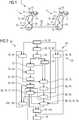
- a hearing aid system 2 is shown with two identical hearing aids 4, which are provided and adapted to be worn behind an ear of a user.
- each hearing aid device 4 comprises a housing 6, which is made of a plastic.
- a microphone 8 with two electromechanical transducers 10 is arranged within the housing 6, which is made of a plastic.
- the two electromechanical transducers 10 it is possible to change a directional characteristic of the microphone 8 by a temporal offset between the means of the respective electromechanical transducer 10 detected acoustic signals is changed.
- the two electromechanical sound transducers 10 are signal-coupled to a signal processing unit 12, which comprises an amplifier circuit.
- the signal processing unit 12 is formed by means of circuit elements, such as electrical and / or electronic components.
- a loudspeaker 14 is signal-wise coupled to the signal processing unit 12, by means of which the audio signals 16 received by the microphones 8 and / or processed by the signal processing unit 12 are output as sound signals. These sound signals are conducted by means of a sound tube not shown near the ear of a user of the hearing aid system 2.
- Each of the hearing aid devices 4 also has a transmitter 18 and a receiver 20, by means of which an exchange of data signals 22 between the two hearing aids 4 takes place.
- the exchange takes place, for example, by radio or inductively.
- the signal processing unit 12, the transmitter 18 and the receiver 20 in each case essentially together form a communication device 24. Due to the exchange of the data signals 22, it is possible for the wearer of the hearing device system 2 to convey a spatial sense of hearing.
- the hearing aid system 2 is configured binaurally.
- a method 26 is shown, according to which the audio signals 16 are transmitted between the two hearing aids 4 by means of their respective communication device 24.
- the audio signal 16 is received by means of a hearing aid 4.
- an input signal 32 is created from this, which consequently corresponds to the audio signal 16 and corresponds to the input signal 32 in FIG FIG. 3 is shown by way of example.
- the audio signal 16 is filtered, for example.
- the input signal 32 is subdivided into time windows 34, which have the same time length and which is, for example, equal to one millisecond. Once the last time window 34 is completed, this time window 34 is divided into a number of frequency channels 36, such as in FIG. 4 shown.
- bandpass filters (frequency-pass filters) 38 which are present within the signal processing unit 16 are used.
- Each of the frequency channels 36 is assigned a particular current channel value 40.
- the input signal 32 is divided into the individual frequency channels 36 and discretized by means of the assignment of the current channel value 40.
- a third operation 42 is carried out on the transmitter 18 side, in which channel values 44 preceding in time are filled. These have been determined, for example, in a previous run of the method 26 or, if the method 26 has not yet been carried out, a standard value is used for this purpose. Also, a fourth step 46 is performed on the receiver 20 side, in which a reconstructed audio signal 48 preceding the time is determined. This corresponds to the temporally preceding channel values 44 and is determined in the same way as the temporally preceding channel values 44.
- a fifth step 50 is carried out in which the number of current channel values 40 are divided into a first current data record 52 and a second current data record 54.
- the current channel values 40 associated with an odd frequency channel 36 are assigned to the first data set 52 and the remaining current channel values 40 are assigned to the second current data set 54 so that the two current data sets 52, 54 have substantially the same number of current channel values 40 ,
- a first prediction 58 for the first current data set 52 is created on the basis of the previously preceding channel values 44.
- a linear prediction is used to generate the first forecast 58.
- a number of forecast values 60 are created, wherein each of the forecast values 60 is associated with one of the current channel values 40 of the first current data set 52.
- the temporally preceding channel values 44 are used, which are assigned to the temporally directly preceding time window 34.
- the respective Forecast value 60 ("precisified value"), for example, uses only the temporally preceding channel values 44 associated with adjacent frequency channels 36.
- a first deviation 60 is created between the first prediction 58 and the first current data set 52, for which the difference between each of the current channel values 40 of the first current data set 52 and each of the prediction values 60 of the first prediction 62 deducted from a difference value.
- the number of forecast values 60 and the number of difference values correspond to the number of current channel values 40 of the first current data set 52.
- a first transmission value 66 is generated by means of a spherical logarithmic quantization, which corresponds to the first deviation 62.
- the first transmission value 66 is one-dimensional.
- the multidimensional first deviation 62 is assigned the one-dimensional first transmission value 66.
- a ninth step 68 is carried out by means of the communication device 24 of the hearing aid 4 having the receiver 20, in which a first auxiliary data set 70 is created by means of the inverse function corresponding to the quantization, which thus corresponds to the first deviation 62.
- a first auxiliary prediction 72 is also generated with prediction values, using the same linear prediction as for generating the first prediction 58. Since the temporally preceding reconstructed output signal 48 corresponds to temporally preceding channel values 44 the first auxiliary prediction 72 of the first prognosis 58. Furthermore, the first auxiliary data set 70 is added to the first auxiliary prognosis 72 in a manner that is valid in terms of value. The resulting data set is a first reconstructed data set 74 which, with the exception of any noise / interference induced due to the use of the spherical logarithmic quantization, corresponds to the first data set 52 present on the transmitter 18 side.
- a second prognosis 78 is calculated with a number of current channel values 44 of the second current data record 54 corresponding number of forecast values 80 ("precisified value").
- the channel values 44 of adjacent frequency channels 36 of the first current data set 52 and the respective temporally preceding value of the same frequency band 36 will be used to generate the prediction values 80. Consequently, the second prediction 78 is generated based on the temporally preceding channel values 44 and the first current data set 52.
- Each of the prediction values 80 corresponds to one of the current channel values 44 of the second current data set 54.
- a second deviation 84 between the second prediction 78 and the second current data set 54 is determined by the difference between each current channel value 40 of the second current record 54 and the respectively associated forecast value 80 of the second forecast 78 is created to form a difference value.
- the number of difference values forms the second deviation 84.
- a second transmission value 88 is generated by means of the second deviation 84 by means of spherical logarithmic quantization, which consequently corresponds to the second deviation 84.
- the second transmission value 86 is also one-dimensional in this case, and, for example, substantially the same spherical logarithmic quantization is used, which is also used to generate the first transmission value 66.
- the second transmission value 88 is transmitted by the transmitter 18 by means of the data signals 22 to the receiver 20 of the hearing aid 4, to which the first transmission value 66 has also been transmitted.
- a second reconstructed data record 92 is created in a thirteenth operation 90.
- a second auxiliary data record 94 is created, wherein a for spherical logarithmic quantization inverse function is performed. Consequently, the second auxiliary data set 94, with the exception of any noise introduced as a result of the quantization, corresponds to the second deviation 84.
- the first reconstructed data set 74 and the preceding reconstructed output signal 48 and the first reconstructed one Dataset 74 created a second auxiliary prognosis 96, for which a linear prediction is used.
- the same coefficients are used as for the generation of the second prediction 78. Therefore, the second auxiliary prediction 96 substantially corresponds to the second prediction 78 due to the substantially same values used to generate the prediction Werteweise the second auxiliary prognosis 96 added.
- the second reconstructed data set 92 is produced on the receiver side based on the temporally preceding reconstructed output signal 48 and the first reconstructed data set 74.
- a subsequent fourteenth operation 98 the first reconstructed data record 74 and the second reconstructed data record 92 are combined into a reconstructed output signal 100, which consequently essentially has the current channel values 40. Any difference is present only due to any quantization effects.
- the output signal 100 is used in a renewed execution of the method 26 as temporally previously reconstructed output signal 48 or at least added to this.
- the reconstructed output signal 100 is transformed from the frequency space to the time period and output, for example, by means of the loudspeaker 14.
- a sixteenth operation 104 is carried out on the transmitter 18 side, in which a third reconstructed data set 106 is created on the basis of the first and second transmission values 66, 88 as well as the first and second prognoses 58, 78.
- the ninth step 68 and the thirteenth step 90 are carried out essentially on the part of the transmitter 18, the first prognosis 58 instead of the first auxiliary prognosis 72 and the first prognosis second prognosis 78 is used instead of the second auxiliary prognosis 96.
- the two reconstructed data sets are added to form the third reconstructed data set 106.
- the third reconstructed data set 106 corresponds to the output signal 100.
- the third reconstructed data set 106 also has any noise due to the quantization used.
- the third reconstructed data record 106 is used in a renewed execution of the method 26 as temporally preceding channel values 44, so that both on the side of the transmitter 18 and on the side of the receiver 20 for generating the respective forecasts 58, 72, 78, 96, the respective same input data be used.
- FIG. 5 is a further embodiment of the preparation of the first prediction 58 and the creation of the second prognosis 78 and consequently also the creation of the two reconstructed data sets 74, 92 shown.
- the first current data record 54 has only one of the current channel values 44, and consequently the first forecast 58 only contains a single forecast value 60.
- the first forecast 58 only contains a single forecast value 60.
- one of the forecast values 80 of the second prognosis 78 is created. which is assigned to the directly adjacent frequency channel 36.
- the current channel value 40 associated with this prognosis value 80 is again used in a further working step to determine a further prognosis value 80 which is assigned to the same in the directly adjacent frequency channel 36, etc.
- all prognosis values 80 are based on the single current channel value 40 of the first actual value Record 54 created.
- the first data record 52 substantially comprises one fifth of all current channel values 40, wherein these are assigned, for example, to frequency channels 36 which are spaced apart from each other by means of four of the frequency channels 36.
- the prognosis values 80 of the second prognosis 78 and consequently also of the second auxiliary prognosis 96 these are used, the number of the prognosis value 80 corresponding to the number of prognosis values 60.
- the current ones are assigned Channel values 40 further prediction values 80 which are assigned to the directly adjacent frequency band 36 are determined.
- the current channel values 40 are divided into a plurality of data records, and a number of deviations are determined and a corresponding transmission value corresponding thereto is transmitted. In other words that will be in FIG. 2 illustrated method 26 executed essentially cascaded.
Description
Die Erfindung betrifft ein Verfahren zum Übertragen eines Audiosignals von einem Sender zu einem Empfänger. Die Erfindung betrifft ferner ein Hörgerät sowie ein Hörgerätesystem mit zwei derartigen Hörgeräten. Das Hörgerät ist bevorzugt ein Hörhilfegerät.The invention relates to a method for transmitting an audio signal from a transmitter to a receiver. The invention further relates to a hearing aid and a hearing aid system with two such hearing aids. The hearing aid is preferably a hearing aid.
Personen, die unter einer Verminderung des Hörvermögens leiden, verwenden üblicherweise ein Hörhilfegerät. Hierbei wird meist mittels eines elektromechanischen Schallwandlers ein Umgebungsschall erfasst. Die erfassten elektrischen Signale werden mittels einer Verstärkerschaltung bearbeitet und mittels eines weiteren elektromechanischen Wandlers in den Gehörgang der Person eingeleitet. Es sind unterschiedliche Arten von Hörhilfegeräten bekannt. Die sogenannten "Hinter-dem-Ohr-Geräte" werden zwischen Schädel und Ohrmuschel getragen. Die Einleitung des verstärkten Schallsignals in den Gehörgang erfolgt hierbei mittels eines Schallschlauchs. Eine weitere gebräuchliche Ausgestaltung eines Hörhilfegeräts ist ein "im-Ohr-Gerät", bei dem das Hörhilfegerät selbst in den Gehörgang eingeführt wird. Mittels dieses Hörhilfegeräts wird folglich der Gehörgang zumindest teilweise verschlossen, sodass außer dem mittels des Hörhilfegeräts erzeugten Schallsignalen kein weiterer Schall - oder lediglich in stark vermindertem Maß Schall - in den Gehörgang eindringen kann.Persons suffering from a reduction in hearing usually use a hearing aid. In this case, an ambient sound is usually detected by means of an electromechanical sound transducer. The detected electrical signals are processed by means of an amplifier circuit and introduced by means of another electromechanical transducer in the ear canal of the person. Different types of hearing aids are known. The so-called "behind-the-ear devices" are worn between the skull and the auricle. The introduction of the amplified sound signal into the ear canal takes place here by means of a sound tube. Another common embodiment of a hearing aid is an "in-ear device" in which the hearing aid itself is inserted into the ear canal. Consequently, the auditory canal is at least partially closed by means of this hearing aid, so that no further sound - or only a greatly reduced amount of sound - can penetrate into the auditory canal, apart from the sound signals generated by the hearing aid.
Sofern die Person unter einer Beeinträchtigung des Hörvermögens beider Ohren leidet, wird ein Hörgerätesystem mit zwei derartigen Hörhilfegerät herangezogen. Hierbei ist jedem der Ohren jeweils eines der Hörhilfegeräte zugeordnet. Um der Person ein räumliches Hören zu ermöglichen, ist es erforderlich, dass die mit einem der Hörhilfegeräte erfassten Audiosignale dem jeweils andern Hörhilfegerät zur Verfügung gestellt werden. Hierbei ist einerseits ein Übertragen mit lediglich einem vergleichsweise geringen Zeitversatz gefordert. Andererseits wirkt der Kopf der Person als Dämpfung, weswegen die Übertragungsrate zwischen den Hörhilfegeräten begrenzt ist. Zudem ist wegen der begrenzten Energiespeicher der Hörhilfegeräte und der ansonsten zu starken Belastung der Person eine Sendeleistung begrenzt.If the person suffers from a hearing impairment in both ears, a hearing aid system with two such hearing aid is used. Here, each of the ears is assigned to one of the hearing aids. In order to allow the person a spatial hearing, it is necessary that with a the hearing aids detected audio signals are provided to each other hearing aid device. On the one hand, this requires transmission with only a comparatively small time offset. On the other hand, the head of the person acts as an attenuation, which is why the transmission rate between the hearing aids is limited. In addition, because of the limited energy storage of hearing aids and the otherwise excessive burden on the person a transmission power limited.
Der Erfindung liegt die Aufgabe zugrunde, ein besonders geeignetes Verfahren zum Übertragen eines Audiosignals von einem Sender zu einem Empfänger sowie ein besonders geeignetes Hörgerät als auch ein besonders geeignetes Hörgerätesystem mit zwei Hörgeräten anzugeben, wobei insbesondere eine Audioqualität verbessert ist, und wobei vorzugsweise eine Übertragungsrate verringert ist. Erfindungsgemäß wird diese Aufgabe hinsichtlich des Verfahrens durch die Merkmale des Anspruchs 1 sowie hinsichtlich des Hörgeräts durch die Merkmale des Anspruchs 7 und hinsichtlich des Hörgerätesystems durch die Merkmale des Anspruchs 8 gelöst. Vorteilhafte Weiterbildungen und Ausgestaltungen sind Gegenstand der jeweiligen Unteransprüche.The invention has for its object to provide a particularly suitable method for transmitting an audio signal from a transmitter to a receiver and a particularly suitable hearing aid and a particularly suitable hearing aid system with two hearing aids, in particular an audio quality is improved, and preferably reduces a transmission rate is. According to the invention, this object is achieved with regard to the method by the features of
Das Verfahren dient dem Übertragen eines Audiosignals von einem Sender zu einem Empfänger, wobei der Sender oder der Empfänger vorzugsweise ein Bestandteil eines Hörgeräts ist. Das jeweils verbleibende Element, also der Sender bzw. der Empfänger, ist geeigneterweise ein Bestandteil eines weiteren Bauteils eines das Hörgerät aufweisenden Hörgerätesystems.The method is for transmitting an audio signal from a transmitter to a receiver, wherein the transmitter or the receiver is preferably a component of a hearing device. The respectively remaining element, that is to say the transmitter or the receiver, is suitably a component of a further component of a hearing device system having the hearing device.
Beispielsweise ist das Hörgerät ein Kopfhörer oder umfasst einen Kopfhörer. Besonders bevorzugt ist das Hörgerät jedoch ein Hörhilfegerät. Das Hörhilfegerät dient der Unterstützung einer unter einer Verminderung des Hörvermögens leidenden Person. Mit anderen Worten ist das Hörhilfegerät ein medizinisches Gerät, mittels dessen beispielsweise ein partieller Hörverlust ausgeglichen wird. Das Hörhilfegerät ist beispielsweise ein "receiver-in-the-canal" - Hörhilfegerät (RIC; Ex-Hörer- Hörhilfegerät), ein Im-Ohr-Hörhilfegerät, wie ein "in-the-ear"- Hörhilfegerät, ein "in-the-canal"- Hörhilfegerät (ITC) oder ein "complete-in-canal"- Hörhilfegerät (CIC), eine Hörbrille, ein Taschenhörhilfegerät, ein Knochenleitungs-Hörhilfegerät oder ein Implantat. Besonders bevorzugt ist das Hörhilfegerät ein Hinter-dem-Ohr-Hörhilfegerät ("Behind-the-Ear" - Hörhilfegerät), das hinter einer Ohrmuschel getragen wird.For example, the hearing aid is a headphone or includes a headphone. However, the hearing aid is particularly preferably a hearing aid. The hearing aid is used to support a person suffering from a reduction in hearing. In other words, the hearing aid is a medical device by means of which, for example, a partial hearing loss is compensated. The hearing aid is, for example, a "receiver-in-the-canal" hearing aid (RIC), an in-the-ear hearing aid, such as an "in-the-ear" hearing aid. an in-the-canal hearing aid (ITC) or a complete-in-canal hearing aid (CIC), a pair of hearing glasses, a pocket hearing aid, a bone conduction hearing aid or an implant. The hearing aid device is particularly preferably a behind-the-ear hearing aid device ("behind-the-ear" hearing aid device) which is worn behind an auricle.
Das Verfahren sieht vor, dass senderseitig ein zu dem Audiosignal korrespondierendes Eingangssignal zeitlich in Zeitfenster unterteilt wird, wobei die Länge der Zeitfenster vorzugsweise gleich ist. Die Länge der Zeitfenster ist beispielsweise zwischen 0,5ms und 2ms und insbesondere gleich 1 ms. Das Eingangssignal ist vorzugsweise das Audiosignal oder in Teil hiervon. Beispielsweise wird das Audiosignal in unterschiedliche Eingangssignale zerlegt, wobei jedes Eingangssignal jeweils in unterschiedliche Zeitfenster unterteilt wird, die sich insbesondere anhand deren Länge unterscheiden. Für ein bestimmtes Zeitfenster wird das Eingangssignal senderseitig in eine Anzahl von Frequenzkanälen aufgeteilt. Senderseitig wird jedem Frequenzkanal ein aktueller Kanalwert zugeordnet. Der Kanalwert ist eine Amplitude und/oder ein Phase oder ein Signalpegel. Senderseitig werden die aktuellen Kanalwerte in einen ersten aktuellen Datensatz und einen zweiten aktuellen Datensatz aufgeteilt, wobei der erste aktuelle Datensatz und der zweite aktuelle Datensatz jeweils mindestens einen der aktuellen Kanalwerte umfassen. Insbesondere weist der erste aktuelle Datensatz lediglich einen einzigen der aktuellen Kanalwerte auf.The method provides that, at the transmitter end, an input signal corresponding to the audio signal is temporally divided into time windows, wherein the length of the time windows is preferably the same. The length of the time window is, for example, between 0.5 ms and 2 ms and in particular equal to 1 ms. The input signal is preferably the audio signal or in part thereof. For example, the audio signal is decomposed into different input signals, each input signal being respectively divided into different time windows, which differ in particular on the basis of their length. For a given time window, the input signal is divided on the transmitter side into a number of frequency channels. On the transmitter side, each frequency channel is assigned a current channel value. The channel value is an amplitude and / or a phase or a signal level. On the transmitter side, the current channel values are divided into a first current data record and a second current data record, wherein the first current data record and the second current data record each comprise at least one of the current channel values. In particular, the first current data record has only a single one of the current channel values.
Anhand zumindest eines zeitlich vorhergehenden Kanalwerts wird senderseitig eine erste Prognose für den ersten aktuellen Datensatz erstellt. Die Erstellung erfolgt insbesondere derart, dass ein Unterschied ("Pädikationsfehler") zwischen dem ersten aktuellen Datensatz und der ersten Prognose möglichst gering ist. Zweckmäßigerweise umfasst die erste Prognose genauso viele Werte wie der erste aktuelle Datensatz. Beispielsweise umfasst die erste Prognose lediglich einen einzigen Wert. Der zeitlich vorhergehende Kanalwert wurde beispielsweise einem der Frequenzkanäle zeitlich ein Zeitfenster früher zugeordnet, beispielsweise dem gleichen Frequenzkanal für den die Prognose erstellt wird, insbesondere sofern der erste aktuelle Datensatz lediglich einen einzigen der aktuellen Kanalwerte umfasst. Vorzugsweise wird eine Anzahl zeitlich vorhergehender Kanalwerte herangezogen, wobei beispielsweise Kanalwerte von anderen Frequenzkanälen und/oder Kanalwerte herangezogen werden, deren zeitlicher Abstand variiert.On the basis of at least one chronologically preceding channel value, a first prognosis for the first current data record is created on the transmitter side. The creation takes place in particular such that a difference ("pädikationsfehler") between the first current record and the first prognosis is as small as possible. Conveniently, the first forecast includes as many values as the first current record. For example, the first forecast includes only a single value. For example, the temporally preceding channel value has been assigned to one of the frequency channels one time slot earlier, for example the same frequency channel for which the prognosis is being compiled, in particular if the first current record comprises only a single one of the current channel values. Preferably, a number of temporally preceding channel values are used, whereby, for example, channel values from other frequency channels and / or channel values are used whose time interval varies.
Senderseitig wird eine erste Abweichung zwischen der ersten Prognose und dem ersten aktuellen Datensatz bestimmt, also um wie viel sich die erste Prognose und der erste aktuelle Datensatz unterscheiden. Ferner wird senderseitig anhand des ersten aktuellen Datensatzes eine zweite Prognose für den zweiten aktuellen Datensatz erstellt. Hierbei werden beispielsweise direkt der erste aktuelle Datensatz und/oder die erste Abweichung herangezogen. Die zweite Prognose umfasst zweckmäßigerweise genauso viele Werte wie der zweite aktuelle Datensatz, wobei die Erstellung der zweiten Prognose insbesondere derart erfolgt, dass ein Unterschied zwischen dem zweiten aktuellen Datensatz und der zweiten Prognose möglichst gering ist. Senderseitig wird eine zweite Abweichung zwischen der zweiten Prognose und dem zweiten aktuellen Datensatz bestimmt, also um wie viel sich die zweite Prognose und der zweite aktuelle Datensatz unterscheiden.On the transmitter side, a first deviation between the first prognosis and the first current dataset is determined, ie by how much the first prognosis and the first current dataset differ. Furthermore, on the transmitter side, based on the first current data record, a second prognosis for the second current data record is created. In this case, for example, the first current data record and / or the first deviation are used directly. The second prognosis expediently comprises just as many values as the second current dataset, wherein the generation of the second prognosis takes place in particular such that a difference between the second current dataset and the second prognosis is as small as possible. On the transmitter side, a second deviation between the second prognosis and the second current dataset is determined, ie by how much the second prognosis and the second current dataset differ.
Ein zur ersten Abweichung korrespondierender erster Übertragungswert wird von dem Sender zu dem Empfänger übertragen, wobei der erste Übertragungswert zweckmäßigerweise zunächst senderseitig anhand der ersten Abweichung erstellt wird. Der erste Übertragungswert weist vorzugsweise eine geringere Dimensionalität oder höchstens die gleiche Dimensionalität wie die erste Abweichung auf, und ist beispielsweise ein eindimensionaler Wert. Ein zur zweiten Abweichung korrespondierender zweiter Übertragungswert wird von dem Sender zu dem Empfänger übertragen, wobei der zweite Übertragungswert zweckmäßigerweise zunächst senderseitig anhand der zweiten Abweichung erstellt wird. Der zweite Übertragungswert weist vorzugsweise eine geringere Dimensionalität oder höchstens die gleiche Dimensionalität wie die zweite Abweichung auf, und ist beispielsweise ein mehrdimensionaler oder besonders bevorzugt ein eindimensionaler Wert. Vorzugsweise ist die Dimensionalität des ersten und des zweiten Übertragungswerts gleich.A first transmission value corresponding to the first deviation is transmitted from the transmitter to the receiver, wherein the first transmission value is expediently first created on the transmitter side based on the first deviation. The first transmission value preferably has a lower dimensionality or at most the same dimensionality as the first deviation, and is for example a one-dimensional value. A second transmission value corresponding to the second deviation is transmitted by the transmitter to the receiver, wherein the second transmission value is expediently first created on the transmitter side on the basis of the second deviation. The second transmission value preferably has a lower dimensionality or at most the same dimensionality as the second deviation, and is for example a multidimensional or particularly preferably a one-dimensional value. Preferably, the dimensionality of the first and second transmission values is the same.
In einem weiteren Arbeitsschritt wird empfängerseitig anhand eines zeitlich vorhergehenden rekonstruierten Ausgangssignals und des übertragenen ersten Übertragungswerts ein erster rekonstruierter Datensatz erstellt. Als zeitlich vorhergehendes rekonstruiertes Ausgangssignal wird zweckmäßigerweise ein Wert oder ein Datensatz herangezogen, der zu dem senderseitig vorhandenen zeitlich vorhergehenden Kanalwert korrespondiert. Beispielsweise wird zu Beginn des Verfahrens als zeitlich vorhergehender Kanalwert bzw. als zeitlich vorhergehendes rekonstruiertes Ausgangssignal Null (0) herangezogen, oder ein bestimmter Wert wird zunächst von dem Sender zu dem Empfänger übertragen, und sowohl sender- als auch empfängerseitig als zeitlich vorhergehenden Kanalwert bzw. als zeitlich vorhergehendes rekonstruiertes Ausgangssignal herangezogen. Der auf diese Weise erstellte erste rekonstruierter Datensatz entspricht somit im Wesentlichen dem senderseitig vorhandenen ersten Datensatz, wobei Unterschiede vorzugsweise lediglich aufgrund der Erstellung des ersten Übertragungswerts vorhanden sind.In a further step, a first reconstructed data record is created on the receiver side on the basis of a previously reconstructed output signal and the transmitted first transmission value. As a temporally preceding reconstructed output signal, it is expedient to use a value or a data record which corresponds to the temporally preceding channel value present at the transmitter end. For example, zero (0) is used at the beginning of the method as the temporally preceding channel value or as a previously reconstructed output signal, or a specific value is first transmitted from the transmitter to the receiver, and both at the transmitter and at the receiver as temporally preceding channel value or used as temporally preceding reconstructed output signal. The first reconstructed data record created in this way thus essentially corresponds to the first data record on the transmitter side, with differences preferably being present only on the basis of the generation of the first transmission value.
In einem weiteren Arbeitsschritt wird empfängerseitig anhand des ersten rekonstruierten Datensatzes und des übertragenen zweiten Übertragungswerts ein zweiter rekonstruierter Datensatz erstellt. Zur Erstellung werden insbesondere zusätzlich weitere empfängerseitig vorhandene Daten herangezogen. Der auf diese Weise erstellte zweite rekonstruierter Datensatz entspricht hierbei im Wesentlichen dem senderseitig vorhandenen zweiten Datensatz, wobei Unterschiede vorzugsweise lediglich aufgrund der Erstellung des zweiten Übertragungswerts und/oder aufgrund von Unterschieden zwischen dem ersten rekonstruierten Datensatz und dem ersten Datensatz vorhanden sind.In a further step, a second reconstructed data record is created on the receiver side based on the first reconstructed data record and the transmitted second transmission value. In particular, additional data that are available on the receiver side are used for the creation. The second reconstructed data record created in this way essentially corresponds to the second data record present on the transmitter side, with differences preferably being present only on the basis of the generation of the second transmission value and / or due to differences between the first reconstructed data record and the first data record.
Der erste rekonstruierte Datensatz und der zweite rekonstruierte Datensatz werden empfängerseitig zu einem rekonstruierten Ausgangssignal zusammengefasst. Die Zusammenfassung ist hierbei insbesondere die Umkehrfunktion zur senderseitigen Aufteilung der aktuellen Kanalwerte in den ersten aktuellen Datensatz und den zweiten aktuellen Datensatz, sodass empfängerseitig die senderseitig vorhandene Aufteilung des Eingangssignals in die Frequenzkanäle vorhanden ist. Das rekonstruierte Ausgangssignal entspricht im Wesentlichen der senderseitig vorhandenen Aufteilung des Eingangssignals in die Frequenzkanäle. Beispielsweise wird empfängerseitig das rekonstruierte Ausgangssignal weiter bearbeitet und die einzelnen Frequenzen zusammengefasst und in den Zeitbereich transferiert. Beispielsweise wird das rekonstruierte Ausgangssignal bei erneutem Ausführen des Verfahrens als das zeitlich vorhergehende rekonstruierte Ausgangssignal herangezogen und verwendet. Vorzugsweise wird das Verfahren nach Ablauf des bestimmten Zeitfensters erneut ausgeführt.The first reconstructed data set and the second reconstructed data record are combined on the receiver side into a reconstructed output signal. The summary here is in particular the inverse function for the transmitter-side distribution of the current channel values into the first current data record and the second current data record, so that the transmitter-side distribution of the input signal into the frequency channels is present on the receiver side. The reconstructed output signal essentially corresponds to the transmitter side existing distribution of the input signal in the frequency channels. For example, on the receiver side, the reconstructed output signal is further processed and the individual frequencies are combined and transferred into the time domain. For example, when the method is executed again, the reconstructed output signal is used and used as the previously preceding reconstructed output signal. Preferably, the method is executed again after the expiry of the specific time window.
Vorzugsweise wird der erste Übertragungswert erstellt, sobald die erste Abweichung erstellt ist, und direkt im Anschluss hieran an den Empfänger übertragen, insbesondere zeitlich vor oder zumindest gleichzeitig vor Erstellung der zweiten Prognose. Insbesondere werden die zweite Prognose/die zweite Abweichung und der erste rekonstruierte Datensatz im Wesentlichen zeitgleich erstellt, sodass eine zeitgleiche Verarbeitung auf Sender- und Empfängerseite erfolgt, weswegen eine Übertragungsgeschwindigkeit erhöht ist.Preferably, the first transmission value is created as soon as the first deviation is created, and then transmitted directly thereafter to the receiver, in particular temporally before or at least simultaneously before the creation of the second prognosis. In particular, the second prediction / the second deviation and the first reconstructed data record are essentially created at the same time, so that a simultaneous processing takes place on the transmitter and receiver side, which is why a transmission speed is increased.
Zweckmäßigerweise wird senderseitig die zweite Prognose auch anhand des zeitlich vorhergehenden Kanalwerts und empfängerseitig der zweite rekonstruierte Datensatz auch anhand des zeitlich vorhergehenden rekonstruierten Ausgangssignals erstellt, wobei beispielsweise eine Anzahl von zeitlich vorhergehenden rekonstruierten Ausgangssignalen bzw. zeitlich vorhergehenden Kanalwerten herangezogen werden. Auf diese Weise ist die zweite Abweichung verkleinert.The second prognosis is expediently also generated on the transmitter side on the basis of the temporally preceding channel value and the second reconstructed dataset on the receiver side based on the temporally preceding reconstructed output signal, wherein, for example, a number of temporally preceding reconstructed output signals or temporally preceding channel values are used. In this way, the second deviation is reduced.
Vorzugsweise wird zur Erstellung der ersten Prognose und des ersten rekonstruierten Datensatzes eine lineare Vorhersage herangezogen. Alternativ oder in Kombination hierzu wird zur Erstellung der zweiten Prognose und des zweiten rekonstruierten Datensatzes eine lineare Vorhersage herangezogen. Mit anderen Worten ist jeder Wert mittels einer Linearkombination erstellt, wobei vorzugsweise eine Anzahl von zeitlich vorhergehenden Kanalwerten, eine Anzahl von zeitlich vorhergehenden rekonstruierten Ausgangssignalen, eine Anzahl von ersten aktuellen Datensätzen bzw. eine Anzahl von ersten rekonstruierten Datensätzen herangezogen wird.Preferably, a linear prediction is used to generate the first prognosis and the first reconstructed dataset. Alternatively or in combination with this, a linear prediction is used to generate the second prognosis and the second reconstructed dataset. In other words, each value is created by means of a linear combination, wherein preferably a number of temporally preceding channel values, a number of temporally preceding reconstructed output signals, a number of first current data records or a number of first reconstructed data records are used.
Zusammenfassend werden die Werte der ersten Prognose, des ersten rekonstruierten Datensatzes, der zweiten Prognose bzw. des zweiten rekonstruierten Datensatzes anhand der Formel 

Beispielsweise wird das Eingangssignal mittels einer Fouriertransformation in die Frequenzkanäle aufgeteilt. Besonders bevorzugt jedoch werden Kanalpassfilter herangezogen, die vorzugsweise in einer Filterbank zusammengefasst sind. Beispielsweise wird der erste Übertragungswert mittels Quantisierung der ersten Abweichung erstellt, und/oder der zweite Übertragungswert wird mittels Quantisierung der zweiten Abweichung erstellt. Hierbei wird der ersten Abweichung der erste Übertragungswert zugeordnet, der zweckmäßigerweise lediglich eine diskrete Anzahl an unterschiedlichen Werten annehmen kann. Der zweiten Abweichung wird der zweite Übertragungswert zugeordnet, der zweckmäßigerweise lediglich eine diskrete Anzahl an unterschiedlichen Werten annehmen kann, wobei die Anzahl beispielsweise unterschiedlich oder gleich zur Anzahl der möglichen Werte des ersten Übertragungswerts ist. Mit anderen Worten ist der erste bzw. zweite Übertragungswert ein diskreter Wert.For example, the input signal is divided into the frequency channels by means of a Fourier transformation. However, particularly preferred channel filter are used, which are preferably combined in a filter bank. For example, the first transmission value is created by quantizing the first deviation, and / or the second transmission value is created by quantizing the second deviation. Here, the first deviation of the first transmission value is assigned, which expediently only can assume a discrete number of different values. The second deviation is assigned the second transmission value, which can expediently assume only a discrete number of different values, the number being for example different or equal to the number of possible values of the first transmission value. In other words, the first or second transmission value is a discrete value.
Bevorzugt wird senderseitig anhand des ersten Übertragungswerts und/oder des zweiten Übertragungswerts sowie anhand der ersten Prognose bzw. zweite Prognose ein dritter rekonstruierter Datensatz erstellt. Der dritte rekonstruierter Datensatz entspricht dem rekonstruierten Ausgangssignal, ist jedoch auf Seiten des Senders vorhanden. Mit anderen Worten wird senderseitig ebenfalls anhand des ersten Übertragungswert bzw. des zweiten Übertragungswerts das Ausgangssignal rekonstruiert, wobei dieses aufgrund der Quantisierung und dem hierdurch bedingten eingeführten Rauschen geringfügig von dem Eingangssignal abweichen kann. Der dritte rekonstruierte Datensatz wird als zeitlich vorhergehender Kanalwert herangezogen. Zumindest wird einer der Werte des dritten rekonstruierten Datensatzes oder sämtliche Werte hierfür herangezogen. Auf diese Weise werden aufgrund der Quantisierung bedingte Abweichungen zwischen dem Ausgangssignal und dem Eingangssignal bei der Erstellung der ersten/zweiten Prognose berücksichtigt, weswegen auch bei einem wiederholten Ausführen des Verfahrens eine maximale Abweichung zwischen dem Eingangssignal und dem rekonstruierten Ausgangssignal gering bleibt, und somit eine hohe Qualität beim Übertragen des Audiosignals vorhanden ist. Insbesondere ist der Vorteil dieses Verfahrens, dass nur Informationen/Signale verwendet werden, die sowohl sender- als auch empfangsseitig vorliegen. Somit sind die rekonstruierten Signale im Sender und Empfänger (zumindest bei fehlerloser Übertragung) identisch.On the transmitter side, a third reconstructed data set is preferably generated on the basis of the first transmission value and / or the second transmission value and on the basis of the first prognosis or second prognosis. The third reconstructed data set corresponds to the reconstructed output signal but is present on the transmitter side. In other words, on the transmitter side, the output signal is also reconstructed on the basis of the first transmission value or the second transmission value, whereby the output signal may deviate slightly from the input signal due to the quantization and the induced noise introduced as a result. The third reconstructed data set is used as temporally preceding channel value. At least one of the values of the third reconstructed data set or all values for this is used. In this way, deviations between the output signal and the input signal due to the quantization are taken into account in the preparation of the first / second prognosis, which is why a maximum deviation between the input signal and the reconstructed output signal remains low even with a repeated execution of the method Quality when transmitting the audio signal is present. In particular, the advantage of this method is that only information / signals are used that are available both at the transmitter and at the receiver. Thus, the reconstructed signals in the transmitter and receiver are identical (at least in the case of faultless transmission).
Geeigneterweise wird zur Quantisierung der ersten Abweichung die gleiche Quantisierung wie zur Quantisierung der zweiten Abweichung herangezogen. Beispielsweise wird eine skalare Quantisierung herangezogen. Besonders bevorzugt ist die Quantisierung eine Vektorquantisierung. Geeigneterweise wird eine sog. gain-shape Vektorquantisierung herangezogen. Das quantisierte Signal wird hierbei aufgeteilt in die Signalform/Vektorform (shape) und einen Skalierungsfaktor (gain). Eine besonders geeignete Form der gain-shape Vektorquantisierung stellt die logarithmische Vektorquantisierung dar, insbesondere die (sphärisch-)logarithmische Vektorquantisierung. Hierbei sind mögliche Signalformen/Vektorformen Punkte auf einer (potentiell) hochdimensionalen Einheitskugel (d.h. mit Radius 1). Der Skalierungsfaktor wird hierbei logarithmisch quantisiert, beispielsweise mit dem bekannten A-law. Als Signalformen/Vektorformen kommen auch andere Formen in Betracht, wie beispielsweise (hochdimensionale) Pyramiden oder Würfel. Eine sphärisch-logarithmische Vektorquantisierung ist beispielsweise aus "
Vorzugsweise wird der erste rekonstruierte Datensatz erstellt, indem anhand des ersten Übertragungswerts ein erster Hilfsdatensatz erstellt wird, der der ersten Abweichung entspricht. Mit anderen Worten würde bei einer Anwendung der gleichen Erstellungsvorschrift, anhand derer der erste Übertragungswert erstellt wird, auf den ersten Hilfsdatensatz, sich der erste Übertragungswert ergeben. Insbesondere wird zur Erstellung des ersten Übertragungswerts eine eineindeutige Funktion herangezogen, und zur Erstellung des ersten Hilfsdatensatzes anhand des ersten Übertragungswerts wird die Umkehrfunktion hiervon verwendet. Ferner wird anhand des zeitlich vorhergehenden rekonstruierten Ausgangssignals eine erste Hilfsprognose erstellt, die zu der ersten Prognose korrespondiert, und dieser vorzugsweise entspricht. Vorzugsweise wird zur Erstellung der ersten Hilfsprognose anhand des zeitlich vorhergehenden rekonstruierten Ausgangssignals vorzugsweise die gleiche Berechnungsvorschrift herangezogen, wie zur Erstellung der ersten Prognose anhand des zeitlich vorhergehenden Kanalwerts. Zweckmäßigerweise ist das zeitlich vorhergehende rekonstruierte Ausgangssignal ebenfalls in Kanäle aufgeteilt, die den Frequenzkanälen entsprechen. Der erste Hilfsdatensatz wird zu der ersten Hilfsprognose addiert. Geeigneterweise erfolgt die Addition werteweise. Mit anderen Worten werden jeweils korrespondierende Werte der beiden Datensätze zusammenaddiert, und diese Summe bildet jeweils einen Wert des ersten rekonstruierten Datensatzes. Zusammenfassend wird jeder Wert des ersten Hilfsdatensatz zu einem Wert der ersten Hilfsprognose addiert. Insbesondere entspricht der erste rekonstruierte Datensatz dem ersten aktuellen Datensatz. Mit anderen Worten sind sämtliche Werte der beiden Datensätze im Wesentlichen gleich.Preferably, the first reconstructed data record is created by using the first transmission value to create a first auxiliary data record which corresponds to the first deviation. In other words, in an application of the same creation rule, on the basis of which the first transfer value is created, to the first auxiliary data record, the first transfer value would result. In particular, a one-to-one function is used to generate the first transmission value, and the inverse function of this is used to generate the first auxiliary data set on the basis of the first transmission value. Furthermore, based on the temporally preceding reconstructed output signal, a first auxiliary prognosis is created, which corresponds to the first prognosis, and this preferably corresponds. Preferably, the same calculation rule is preferably used to generate the first auxiliary prognosis on the basis of the previously reconstructed output signal, as for the generation of the first prognosis on the basis of the temporally preceding channel value. Conveniently, the temporally preceding reconstructed output signal is also divided into channels corresponding to the frequency channels. The first auxiliary data set is added to the first auxiliary prognosis. Suitably, the addition takes place in a value-wise manner. In other words, corresponding values of the two data sets are added together in each case, and this sum forms a value in each case of the first reconstructed data set. In summary, each value of the first auxiliary data set is added to a value of the first auxiliary prognosis. In particular, the first reconstructed record corresponds to the first current record. In other words, all values of the two data sets are substantially the same.
Vorzugsweise wird der zweite rekonstruierte Datensatz erstellt, indem anhand des zweiten Übertragungswerts ein zweiter Hilfsdatensatz erstellt wird, der der zweiten Abweichung entspricht. Mit anderen Worten würde bei einer Anwendung der gleichen Erstellungsvorschrift, anhand derer der zweite Übertragungswert erstellt wird, auf den zweiten Hilfsdatensatz, sich der zweite Übertragungswert ergeben. Insbesondere wird zur Erstellung des zweiten Übertragungswerts eine eineindeutige Funktion herangezogen, und zur Erstellung des zweiten Hilfsdatensatzes anhand des zweiten Übertragungswerts wird die Umkehrfunktion hiervon verwendet. Ferner wird anhand des ersten rekonstruierten Datensatzes eine zweite Hilfsprognose erstellt, die zu der zweiten Prognose korrespondiert, und dieser vorzugsweise entspricht. Vorzugsweise wird zur Erstellung der zweiten Hilfsprognose anhand des ersten rekonstruierten Datensatzes vorzugsweise die gleiche Berechnungsvorschrift herangezogen, wie zur Erstellung der zweiten Prognose anhand des ersten Datensatzes. Der zweite Hilfsdatensatz wird zu der zweiten Hilfsprognose addiert. Geeigneterweise erfolgt die Addition werteweise. Mit anderen Worten werden jeweils korrespondierende Wert der beiden Datensätze zusammenaddiert, und diese Summe bildet jeweils einen Wert des zweiten rekonstruierten Datensatzes. Zusammenfassend wird jeder Wert des zweiten Hilfsdatensatz zu einem Wert der zweiten Hilfsprognose addiert. Insbesondere entspricht der zweite rekonstruierte Datensatz dem zweiten aktuellen Datensatz. Mit anderen Worten sind sämtliche Werte der beiden Datensätze im Wesentlichen gleich.Preferably, the second reconstructed data record is created by using the second transmission value to create a second auxiliary data record which corresponds to the second deviation. In other words, in an application of the same creation rule, on the basis of which the second transfer value is created, to the second auxiliary data record, the second transfer value would result. In particular, a one-to-one function is used to generate the second transmission value, and the inverse function thereof is used to generate the second auxiliary data set on the basis of the second transmission value. Furthermore, based on the first reconstructed data set, a second auxiliary prognosis is created, which corresponds to the second prognosis, and this preferably corresponds. Preferably, to generate the second auxiliary prognosis, the same calculation rule is preferably used on the basis of the first reconstructed data set as for the generation of the second prognosis on the basis of the first data set. The second auxiliary data set is added to the second auxiliary prognosis. Suitably, the addition takes place in a value-wise manner. In other words, the corresponding value of the two data sets is added together in each case, and this sum forms in each case a value of the second reconstructed data record. In summary, each value of the second auxiliary data set is added to a value of the second auxiliary prognosis. In particular, the second reconstructed record corresponds to the second current record. In other words, all values of the two data sets are substantially the same.
Sofern der dritte rekonstruierter Datensatz verwendet wird, wird vorzugsweise senderseitig sowohl der erste als auch der zweite Hilfsdatensatz erstellt und jeweils zu den Werten der ersten bzw. zweiten Prognose addiert. Sofern folglich aufgrund der Quantisierung ein Rauschen in den ersten bzw. zweiten Übertragungswert eingebracht wird, wird dieses bei einer erneuten Ermittlung der ersten bzw. zweiten Prognose bzw. Hilfsprognose sowohl sender- als auch empfängerseitig berücksichtigt.If the third reconstructed data record is used, preferably both the first and the second auxiliary data record are created on the transmitter side and in each case added to the values of the first or second prognosis. If, as a result of the quantization, noise is introduced into the first or second transmission value, this is determined when the first one is determined again or second prognosis or auxiliary prognosis, both on the transmitter and on the receiver side.
Vorzugsweise wird die erste und/oder zweite Abweichung erstellt, indem die Differenz zwischen jedem aktuellen Kanalwert des ersten aktuellen Datensatzes bzw. des zweiten aktuellen Datensatzes und einem zugeordneten Prognosewert der ersten bzw. zweiten Prognose zur Bildung eines Differenzwerts erstellt wird. Mit anderen Worten wird jeder aktuelle Kanalwert des jeweiligen aktuellen Datensatzes von einem korrespondierenden Prognosewert der jeweiligen Prognose abgezogen, bzw. es wird jeder Prognosewert der jeweiligen Prognose von dem korrespondierenden aktuellen Kanalwert des jeweiligen aktuellen Datensatzes abgezogen. Die hierbei erstellten Differenzwerte bilden die erste bzw. zweite Abweichung. Mit anderen Worten ist die erste/zweite Abweichung ein Datensatz/Vektor, und die Anzahl der Differenzwerte der ersten Abweichung ist gleich der Anzahl der aktuellen Kanalwerte des ersten aktuellen Datensatzes, die gleich der Anzahl der Prognosewerte der ersten Prognose ist. Auch ist die Anzahl der Differenzwerte der zweiten Abweichung gleich der Anzahl der aktuellen Kanalwert des zweiten aktuellen Datensatzes und gleich der Anzahl der Prognosewerte der zweiten Prognose. Die Erstellung der einzelnen Prognosewerte der ersten Prognose erfolgt insbesondere unabhängig voneinander, und die Prognosewerte werden vorzugsweise zumindest teilweise zeitlich parallel erstellt. Alternativ oder besonders bevorzugt in Kombination hierzu erfolgt die Erstellung der einzelnen Prognosewerte der zweiten Prognose insbesondere unabhängig voneinander, und die Prognosewerte werden vorzugsweise zumindest teilweise zeitlich parallel erstellt.Preferably, the first and / or second deviation is created by creating the difference between each current channel value of the first current data set or the second current data set and an associated prediction value of the first or second prediction to form a difference value. In other words, each current channel value of the respective current data record is subtracted from a corresponding forecast value of the respective prognosis, or each forecast value of the respective prognosis is subtracted from the corresponding current channel value of the respective current data record. The difference values created here form the first or second deviation. In other words, the first / second deviation is a data set / vector, and the number of difference values of the first deviation is equal to the number of current channel values of the first current data set equal to the number of prediction values of the first prediction. Also, the number of difference values of the second deviation is equal to the number of the current channel value of the second current data set and equal to the number of forecast values of the second prognosis. The generation of the individual forecast values of the first prognosis takes place, in particular, independently of one another, and the prognosis values are preferably created at least partially in parallel over time. Alternatively or particularly preferably in combination with this, the generation of the individual forecast values of the second prognosis takes place in particular independently of one another, and the prognosis values are preferably created at least partially in parallel over time.
Beispielsweise werden die aktuellen Kanalwerte im Wesentlichen hälftig auf den ersten aktuellen Datensatz und den zweiten aktuellen Datensatz aufgeteilt, sodass der erste aktuelle Datensatz folglich im Wesentlichen die gleiche Anzahl an Kanalwerten aufweist wie der zweite aktuellen Datensatz, wobei sich beispielsweise die Anzahlen um eins (1) unterscheiden. Hierbei wird insbesondere jedem Frequenzkanal ein Index zugeordnet, wobei zweckmäßigerweise sämtliche Frequenzkanäle mit einem geraden Index einem der aktuellen Datensätze und die Frequenzkanäle mit einem ungeraden Index dem verbleibenden aktuellen Datensatz zugeordnet werden. Zum Beispiel werden sämtliche Frequenzkanäle mit einem ungeraden Index dem ersten aktuellen Datensatz zugeordnet. Aufgrund des Vorgehens weist somit auch insbesondere der erste rekonstruierte Datensatz und der zweite rekonstruierte Datensatz im Wesentlichen die gleiche Anzahl an rekonstruierten Kanalwerten auf.For example, the current channel values are split substantially equally between the first current record and the second current record, so that the first current record thus has substantially the same number of channel values as the second current record, for example, the numbers being one (1) differ. In this case, in particular each frequency channel is assigned an index, wherein expediently all frequency channels with a straight index one of the current data sets and the frequency channels with an odd index the remaining current data set be assigned. For example, all frequency channels with an odd index are assigned to the first current record. As a result of the procedure, in particular the first reconstructed data record and the second reconstructed data record also have essentially the same number of reconstructed channel values.
Zusammenfassend wird insbesondere das Eingangssignal in eine Anzahl N von Frequenzkanälen zerlegt. Somit entsteht ein Signal, welches sowohl von der Zeit als auch vom Frequenzkanal abhängt. Das Signal stellt somit die aktuellen Kanalwerte und die zeitlich vorhergehenden Kanalwerte dar. Das Signal kann mit x(t,k) bezeichnet werden, wobei t den (diskreten) Zeitindex und k den Kanalindex bezeichnet. Die Gesamtheit der aktuellen Kanalwerte ist folglich x(t1,k), wobei der Zeitindex t1 den aktuellen Zeitpunkt/das aktuelle Zeitfenster bezeichnet. Jedes x(t,k) ist im Allgemeinen eine komplexe Zahl. Für eine kompakte mathematische Darstellung des Verfahrens ist beispielsweise x(t,k < 1) = 0. Ebenfalls soll x(t,k>N+1) = 0 sein.In summary, in particular, the input signal is decomposed into a number N of frequency channels. This creates a signal that depends on both the time and the frequency channel. The signal thus represents the current channel values and the temporally preceding channel values. The signal can be denoted by x (t, k), where t denotes the (discrete) time index and k the channel index. The totality of the current channel values is thus x (t1, k), where the time index t1 denotes the current time / window. Every x (t, k) is generally a complex number. For a compact mathematical representation of the method, for example, x (t, k <1) = 0. Also, let x (t, k> N + 1) = 0.
Die Erstellung der ersten bzw. zweiten Prognose erfolgt insbesondere anhand der Formel, wobei der aktuellen Zeitpunkt/das aktuelle Zeitfenster mit t bezeichnet ist, 
"x Dach" bezeichnet hierbei die erste und zweite Prognose ("Prädiktionswert") und "x Tilde" den rekonstruierten Wert/die aktuellen bzw. zeitlich vorhergehenden Kanalwerte. Wenn der zweite Term vorhanden ist, ist "x Dach" beispielsweise der zweiten Prognose, und sonst der ersten Prognose zugeordnet.The first and second forecasts are created in particular using the formula, wherein the current time / the current time window is denoted by t,
"x roof" here denotes the first and second forecasts ("prediction value") and "x tilde" the reconstructed value / the current or temporally preceding channel values. For example, if the second term exists, then "x Roof" is assigned to the second forecast, and otherwise to the first forecast.
Die Doppelsumme in obiger Formel leistet einen Beitrag zum Prädiktionswert basierend allein auf Werten aus vorhergehenden Zeitschritten (aufgrund von "t-i") (zeitlich vorhergehenden Kanalwerte), allerdings nicht zwingend aus demselben Kanal (sondern aus Kanal k-m, wobei m auch 0 sein kann). Die Tatsache, dass die zweite Summe bis l_m geht, trägt der Tatsache Rechnung, dass in unterschiedlichen Kanälen unterschiedlich weit "in die Vergangenheit geschaut" werden kann.The double sum in the above formula makes a contribution to the prediction value based solely on values from previous time steps (due to "ti") (temporally preceding channel values), but not necessarily from the same Channel (but from channel km, where m can also be 0). The fact that the second sum goes up to l_m takes into account the fact that different channels can look "differently" into the past.
Aufgrund der zweiten Summe werden auch Werte aus dem gleichen Zeitschritt (aktuelle Kanalwerte) verwendet. Hierzu können prinzipiell alle Werte aus Kanälen herangezogen werden, welche bereits berechnet sind. In obiger Formel wird hierbei "von unten nach oben" vorgegangen. Der unterste Kanal (Kanal Nummer 1) wird nur aus zeitlich vorangegangenen Werten prädiziert. Das folgt auch aus der Gleichung oben aufgrund des Nullsetzens der (hypothetischen) Kanäle mit Kanalnummern < 1. Im nächsten Schritt (Für Kanal Nummer 2) kann nun Kanal Nummer 1, also x Tilde(t,1) herangezogen werden usw. Denkbar ist das Verfahren natürlich auch in umgekehrter Kanalreihenfolge und prinzipiell sogar mit einer beliebigen Kanalreihenfolge. Sofern also die zweite Summe vorhanden ist, bezeichnet "x Dach" vorzugsweise einen Prognosewert der zweiten Prognose.Due to the second sum, values from the same time step (current channel values) are also used. In principle, all values from channels that have already been calculated can be used for this purpose. In the above formula, this is done "from bottom to top". The lowest channel (channel number 1) is predicted only from temporally preceding values. This also follows from the equation above due to the zeroing of the (hypothetical) channels with channel numbers <1. In the next step (for channel number 2)
Beispielsweise wird die Prädiktion basierend auf zeitlich vorangegangenen Werten (die Doppelsumme) parallel in mehreren Frequenzkanälen durchgeführt, und folglich die erste Prognose erstellt. Hierbei können die Frequenzkanäle beispielsweise Äquidistant gewählt werden, wobei auch eine beliebige Auswahl möglich ist, wie beispielsweise jeder zweite Frequenzkanal. Dieses Verfahren bringt den Vorteil, dass die nun parallel berechenbaren Werte mittels Vektorquantisierung quantisiert werden können, was i.A. zu einem geringeren Quantisierungsrauschen führt. In einem zweiten und folgenden Schritt können nun die im vorhergehenden Schritt erlangten rekonstruierten Werte desselben Zeitschrittes für die Prädiktion herangezogen werden. Mit anderen Worten wird die zweite Prognose erstellt. Zum Beispiel erfolgt die Erstellung für alle ungeraden Kanalnummern.For example, the prediction based on temporally preceding values (the double sum) is performed in parallel in a plurality of frequency channels, and thus the first prediction is made. Here, the frequency channels can be chosen, for example, equidistant, with any selection is possible, such as every other frequency channel. This method has the advantage that the values which can now be calculated in parallel can be quantized by means of vector quantization, which i.a. leads to a lower quantization noise. In a second and following step, the reconstructed values of the same time step obtained in the previous step can now be used for the prediction. In other words, the second forecast is created. For example, the creation is done for all odd channel numbers.
Das Hörgerät weist eine Kommunikationseinrichtung zum Senden und/oder Empfangen eines Audiosignals auf. Hierfür umfasst die Kommunikationseinrichtung einen Sender bzw. einen Empfänger. Die Kommunikationseinrichtung ist geeignet sowie vorgesehen und eingerichtet ein Verfahren zum Übertragen eines Audiosignals von dem Sender bzw. zu dem Empfänger durchzuführen. Das Verfahren sieht hierbei vor, dass senderseitig ein zu dem Audiosignal korrespondierendes Eingangssignal für ein bestimmtes Zeitfenster in eine Anzahl von Frequenzkanälen aufgeteilt wird, sowie dass senderseitig jedem Frequenzkanal ein aktueller Kanalwert zugeordnet wird. Ferner werden senderseitig die aktuellen Kanalwerte in einen ersten aktuellen Datensatz und einen zweiten aktuellen Datensatz aufgeteilt, und senderseitig wird anhand eines zeitlich vorhergehenden Kanalwerts eine erste Prognose für den ersten aktuellen Datensatz erstellt. In einem weiteren Arbeitsschritt wird senderseitig eine erste Abweichung zwischen der ersten Prognose und dem ersten aktuellen Datensatz bestimmt sowie senderseitig anhand des ersten aktuellen Datensatzes eine zweite Prognose für den zweiten aktuellen Datensatz erstellt. Senderseitig wird eine zweite Abweichung zwischen der zweiten Prognose und dem zweiten aktuellen Datensatz bestimmt.The hearing device has a communication device for transmitting and / or receiving an audio signal. For this purpose, the communication device comprises a transmitter or a receiver. The communication device is suitable as well as provided and set up a method for transmitting an audio signal from the transmitter or to the receiver. In this case, the method provides that, on the transmitter side, an input signal corresponding to the audio signal for a specific time window is divided into a number of frequency channels, and that a current channel value is assigned to each frequency channel on the transmitter side. Furthermore, the current channel values are divided on the transmitter side into a first current data record and a second current data record, and on the transmitter side, a first prognosis for the first current data record is created on the basis of a preceding channel value. In a further step, a first deviation between the first prognosis and the first current dataset is determined on the transmitter side, and a second prognosis for the second current dataset is created on the transmitter side on the basis of the first current dataset. On the transmitter side, a second deviation between the second prognosis and the second current dataset is determined.
Ferner sieht das Verfahren vor, dass ein zur ersten Abweichung korrespondierender erster Übertragungswert sowie ein zur zweiten Abweichung korrespondierender zweiter Übertragungswert von dem Sender zu dem Empfänger übertragen werden. Empfängerseitig wird anhand eines zeitlich vorhergehenden rekonstruierten Ausgangssignals und des übertragenen ersten Übertragungswerts ein erster rekonstruierter Datensatz erstellt, und empfängerseitig wird anhand des ersten rekonstruierten Datensatzes und des übertragenen zweiten Übertragungswerts ein zweiter rekonstruierter Datensatz erstellt. In einem weiteren Arbeitsschritt wird empfängerseitig der erste rekonstruierte Datensatz und der zweite rekonstruierte Datensatz zu einem rekonstruierten Ausgangssignal zusammengefasst.Furthermore, the method provides that a first transmission value corresponding to the first deviation and a second transmission value corresponding to the second deviation are transmitted from the transmitter to the receiver. On the receiver side, a first reconstructed data record is created based on a temporally preceding reconstructed output signal and the transmitted first transmission value, and on the receiver side, a second reconstructed data record is created on the basis of the first reconstructed data record and the transmitted second transmission value. In a further working step, the receiver side reconciles the first reconstructed data set and the second reconstructed data record into a reconstructed output signal.
Sofern die Kommunikationseinrichtung lediglich den Sender umfasst, werden hierbei insbesondere lediglich die senderseitigen Arbeitsschritte sowie ein Arbeitsschritt zum Übertragen der Abweichungen durchgeführt. Falls die Kommunikationseinrichtung lediglich den Empfänger aufweist, werden insbesondere lediglich die empfängerseitigen Arbeitsschritte sowie ein Arbeitsschritt zum Empfangen der Abweichungen durchgeführt. Zweckmäßigerweise erfolgt die Übertragung drahtlos, beispielsweise induktiv oder mittels Funk.If the communication device only comprises the transmitter, in this case in particular only the transmitter-side working steps and a work step for transmitting the deviations are carried out. If the communication device only has the receiver, in particular only the receiver-side working steps and a work step for receiving the deviations are carried out. Conveniently, the transmission is wireless, such as inductive or wireless.
Das Hörgerät umfasst bevorzugt einen Sensor, mittels dessen bei Betrieb ein Audiosignal erfasst wird. Der Sensor ist bevorzugt ein elektromechanischer Schallwandler, wie ein Mikrofon. Beispielsweise ist das Eingangssignal das Audiosignal oder das Eingangssignal wird anhand des Audiosignals erstellt. Beispielsweise ist das Eingangssignal ein Teil des Audiosignals, oder entspricht einem bestimmten Frequenzbereich des Audiosignals. Zur Erstellung des Eingangssignals aus dem Audiosignals umfasst das Hörgerät beispielsweise einen Signalverarbeitungseinheit und/oder Filter. Das Hörgerät umfasst bevorzugt eine Verstärkerschaltung, mittels derer das Audiosignal verstärkt werden kann. Vorzugsweise umfasst das Hörgerät einen Aktor, mittels dessen ein Schallsignal erstellt wird, wie einen Lautsprecher, und der zur Ausgabe des Ausgangssignals bzw. des rekonstruierten Ausgangssignals geeignet, und beispielsweise vorgesehen und geeignet ist.The hearing device preferably comprises a sensor, by means of which an audio signal is detected during operation. The sensor is preferably an electromechanical transducer, such as a microphone. For example, the input signal is the audio signal or the input signal is generated based on the audio signal. For example, the input signal is a part of the audio signal, or corresponds to a certain frequency range of the audio signal. To generate the input signal from the audio signal, the hearing device comprises, for example, a signal processing unit and / or filter. The hearing device preferably comprises an amplifier circuit by means of which the audio signal can be amplified. Preferably, the hearing aid comprises an actuator, by means of which a sound signal is generated, such as a loudspeaker, and which is suitable for outputting the output signal or the reconstructed output signal, and is provided and suitable, for example.
Beispielsweise ist das Hörgerät ein Kopfhörer oder umfasst einen Kopfhörer. Besonders bevorzugt ist das Hörgerät jedoch ein Hörhilfegerät. Das Hörhilfegerät dient der Unterstützung einer unter einer Verminderung des Hörvermögens leidenden Person. Mit anderen Worten ist das Hörhilfegerät ein medizinisches Gerät, mittels dessen beispielsweise ein partieller Hörverlust ausgeglichen wird. Das Hörhilfegerät ist beispielsweise ein "receiver-in-the-canal" - Hörhilfegerät (RIC; Ex-Hörer- Hörhilfegerät), ein Im-Ohr-Hörhilfegerät, wie ein "in-the-ear"- Hörhilfegerät, ein "in-the-canal"- Hörhilfegerät (ITC) oder ein "complete-in-canal"- Hörhilfegerät (CIC), eine Hörbrille, ein Taschenhörhilfegerät, ein Knochenleitungs-Hörhilfegerät oder ein Implantat. Besonders bevorzugt ist das Hörhilfegerät ein Hinter-dem-Ohr-Hörhilfegerät ("Behind-the-Ear" - Hörhilfegerät), das hinter einer Ohrmuschel getragen wird.For example, the hearing aid is a headphone or includes a headphone. However, the hearing aid is particularly preferably a hearing aid. The hearing aid is used to support a person suffering from a reduction in hearing. In other words, the hearing aid is a medical device by means of which, for example, a partial hearing loss is compensated. The hearing aid is, for example, a "receiver-in-the-canal" hearing aid (RIC), an in-the-ear hearing aid such as an in-the-ear hearing aid, an in-the-ear -canal "- a hearing aid (ITC) or a complete-in-canal hearing aid (CIC), a pair of hearing glasses, a pocket hearing aid, a bone conduction hearing aid or an implant. The hearing aid device is particularly preferably a behind-the-ear hearing aid device ("behind-the-ear" hearing aid device) which is worn behind an auricle.
Das Hörgerät ist vorgesehen und eingerichtet, am menschlichen Körper getragen zu werden. Mit anderen Worten umfasst das Hörgerät bevorzugt eine Haltevorrichtung, mittels dessen eine Befestigung am menschlichen Körper möglich ist. Sofern es sich bei dem Hörgerät um ein Hörhilfegerät handelt, ist das Hörgerät vorgesehen und eingerichtet, beispielsweise hinter dem Ohr oder innerhalb eines Gehörgangs angeordnet zu werden. Insbesondere ist das Hörgerät kabellos und dafür vorgesehen und eingerichtet, zumindest teilweise in einen Gehörgang eingeführt zu werden. Beispielsweise ist das Hörgerät ein Bestandteil eines Hörgerätesystems, das ein weiteres Hörgerät oder ein weiteres Gerät umfasst, wie ein Richtmikrofon oder ein sonstiges, ein Mikrofon aufweisendes Gerät. Hierbei umfasst das Gerät vorzugsweise den Sender und das Hörgerät den Empfänger, und die Übertragung des Audiosignals zwischen dem Sender und dem Empfänger erfolgt gemäß dem Verfahren.The hearing aid is provided and adapted to be worn on the human body. In other words, the hearing aid preferably comprises a holding device, by means of which an attachment to the human body is possible. If the hearing device is a hearing aid device, the hearing device is provided and set up, for example, to be arranged behind the ear or within an auditory canal. In particular, the hearing aid is wireless and provided and set up, at least partially inserted into an ear canal to become. For example, the hearing aid is a component of a hearing aid system which comprises a further hearing aid or a further device, such as a directional microphone or another device having a microphone. In this case, the device preferably comprises the transmitter and the hearing device the receiver, and the transmission of the audio signal between the transmitter and the receiver is carried out according to the method.
Das Hörgerätesystem umfasst bevorzugt zwei Hörgeräte, die jeweils eine Kommunikationseinrichtung aufweisen, die zum Senden und/oder Empfangen eines Audiosignals gemäß dem obigen Verfahren vorgesehen und eingerichtet sind. Hierbei ist das Hörgerätesystem geeignet sowie vorgesehen und eingerichtet, Audiosignale zwischen den beiden Hörgeräten mittels deren jeweiliger Kommunikationseinrichtungen zu übertragen, wobei obiges Verfahren durchgeführt wird. Insbesondere weist jede der Kommunikationseinrichtungen jeweils einen Sender und einen Empfänger auf, und die Audiosignale werden zwischen den beiden Kommunikationseinrichtungen übertragen, zumindest von einem der Hörgeräte zu dem verbleibenden. Zweckmäßigerweise erfolgt die Übertragung drahtlos, beispielsweise induktiv oder mittels Funk.The hearing aid system preferably comprises two hearing aids, each having a communication device, which are provided and arranged for transmitting and / or receiving an audio signal according to the above method. In this case, the hearing device system is suitable as well as provided and set up to transmit audio signals between the two hearing aids by means of their respective communication devices, wherein the above method is performed. In particular, each of the communication devices each has a transmitter and a receiver, and the audio signals are transmitted between the two communication devices, at least from one of the hearing aids to the remaining one. Conveniently, the transmission is wireless, such as inductive or wireless.
Besonders bevorzugt ist das Hörgerätesystem ein Hörhilfesystem. Das Hörhilfesystem dient der Unterstützung einer unter Verminderung des Hörvermögens leidenden Person. Mit anderen Worten ist das Hörhilfesystem ein medizinisches Gerät, mittels dessen beispielsweise ein partieller Hörverlust ausgeglichen wird. Das Hörhilfesystem umfasst zweckmäßigerweise ein Hinter-dem-Ohr-Hörhilfegerät, das hinter einer Ohrmuschel getragen wird, ein "receiver-in-the-canal" - Hörhilfegerät (RIC; Ex-Hörer- Hörhilfegerät), ein Im-Ohr- Hörhilfegerät, wie ein "in-the-ear"- Hörhilfegerät, ein "in-the-canal"- Hörhilfegerät (ITC) oder ein "complete-in-canal"- Hörhilfegerät (CIC), eine Hörbrille, ein Taschenhörhilfegerät, ein Knochenleitungs-Hörhilfegerät oder aber ein Implantat. Das Hörgerätesystem ist insbesondere vorgesehen und eingerichtet, am menschlichen Körper getragen zu werden. Mit anderen Worten umfasst das Hörgerätesystem bevorzugt eine Haltevorrichtung, mittels dessen eine Befestigung am menschlichen Körper ermöglicht ist. Sofern es sich bei dem Hörgerätesystem um ein Hörhilfesystem handelt, ist zumindest eines der Hörgeräte vorgesehen und eingerichtet, beispielsweise hinter dem Ohr oder innerhalb eines Gehörgangs angeordnet zu werden. Insbesondere ist das Hörgerätesystem kabellos und dafür vorgesehen und eingerichtet, zumindest teilweise in einen Gehörgang eingeführt zu werden. Besonders bevorzugt umfasst das Hörgerätesystem einen Energiespeicher, mittels dessen eine Energieversorgung bereitgestellt ist.The hearing aid system is particularly preferably a hearing aid system. The hearing aid system is used to support a person suffering from a reduction in hearing. In other words, the hearing aid system is a medical device by means of which, for example, a partial hearing loss is compensated. The hearing aid system expediently comprises a behind-the-ear hearing aid that is worn behind an auricle, a "receiver-in-the-canal" hearing aid (RIC), an in-the-ear hearing aid, such as an in-the-ear hearing aid, an in-the-canal hearing aid (ITC) or a complete-in-canal hearing aid (CIC), a pair of hearing-glasses, a pocket-hearing aid, a bone conduction hearing aid or but an implant. The hearing aid system is in particular provided and adapted to be worn on the human body. In other words, the hearing aid system preferably comprises a holding device, by means of which an attachment to the human body is made possible. If the hearing aid system is a hearing aid system, then at least one of the hearing aids provided and set up, for example, to be arranged behind the ear or within an ear canal. In particular, the hearing aid system is wireless and designed and arranged to be at least partially inserted into an ear canal. Particularly preferably, the hearing device system comprises an energy store, by means of which a power supply is provided.
Die im Zusammenhang mit dem Verfahren beschriebenen Weiterbildungen und Vorteile sind sinngemäß auch auf das Hörgerät bzw. das Hörgerätesystem zu übertragen und umgekehrt.The further developments and advantages described in connection with the method are also to be transferred analogously to the hearing device or the hearing device system and vice versa.
Nachfolgend werden Ausführungsbeispiele der Erfindung anhand einer Zeichnung näher erläutert. Darin zeigen:
- Fig. 1
- schematisch ein Hörgerätesystem mit zwei Hörgeräten,
- Fig. 2
- ein Verfahren zum Übertragen eines Audiosignals zwischen den beiden Hörgeräten,
- Fig. 3
- ein zu dem Audiosignal korrespondierendes Eingangssignal, und
- Fig. 4 - 6
- jeweils teilweise Datensätze.
- Fig. 1
- schematically a hearing aid system with two hearing aids,
- Fig. 2
- a method for transmitting an audio signal between the two hearing aids,
- Fig. 3
- an input signal corresponding to the audio signal, and
- Fig. 4-6
- each partial records.
Einander entsprechende Teile sind in allen Figuren mit den gleichen Bezugszeichen versehen.Corresponding parts are provided in all figures with the same reference numerals.
In
Ferner ist mit der Signalverarbeitungseinheit 12 ein Lautsprecher 14 signaltechnisch gekoppelt, mittels dessen die mit den Mikrofonen 8 aufgenommenen und/oder mittels der Signalverarbeitungseinheit 12 bearbeiteten Audiosignale 16 als Schallsignale ausgegeben werden. Diese Schallsignale werden mittels eines nicht nähe dargestellten Schallschlauchs in das Ohr eines Benutzers des Hörgerätesystems 2 geleitet.Furthermore, a
Jedes der Hörhitfegeräte 4 weist ferner einen Sender 18 und einen Empfänger 20 auf, mittels derer ein Austausch von Datensignalen 22 zwischen den beiden Hörhilfegeräten 4 erfolgt. Der Austausch erfolgt beispielsweise mittels Funk oder induktiv. Die Signalverarbeitungseinheit 12, der Sender 18 und der Empfänger 20 bilden hierbei zusammen jeweils im Wesentlichen eine Kommunikationseinrichtung 24. Aufgrund des Austauschs der Datensignale 22 ist es ermöglicht dem Träger des Hörgerätesystems 2 ein räumliches Hörgefühl zu vermitteln. Zusammenfassend ist das Hörgerätesystem 2 binaural ausgestaltet.Each of the hearing aid devices 4 also has a
In
Ferner wird nach Ausführung des ersten Arbeitsschritts 16 auf Seiten des Senders 18 ein dritter Arbeitsschritt 42 ausgeführt, bei dem zeitlich vorhergehende Kanalwerte 44 befüllt werden. Diese sind beispielsweise in einem vorhergehenden Durchlauf des Verfahrens 26 ermittelt worden oder, sofern das Verfahren 26 noch nicht ausgeführt wurde, wird hierfür ein Standardwert herangezogen. Auch wird auf Seiten des Empfängers 20 ein vierter Arbeitsschritt 46 ausgeführt, bei dem ein zeitlich vorhergehendes rekonstruiertes Audiosignal 48 bestimmt wird. Dieses entspricht den zeitlich vorhergehenden Kanalwerten 44 und ist auf die gleiche Weise ermittelt, wie die zeitlich vorhergehenden Kanalwerte 44.Furthermore, after execution of the first working step 16, a third operation 42 is carried out on the
Ferner wird ein fünfter Arbeitsschritt 50 ausgeführt, bei dem die Anzahl der aktuellen Kanalwerte 40 in einen ersten aktuellen Datensatz 52 und einen zweiten aktuellen Datensatz 54 aufgeteilt werden. Hierbei werden die aktuellen Kanalwerte 40, die einem ungeraden Frequenzkanal 36 zugeordnet sind, dem ersten Datensatz 52 und die verbleibenden aktuellen Kanalwerte 40 dem zweiten aktuellen Datensatz 54 zugeordnet, sodass die beiden aktuellen Datensätze 52, 54 im Wesentlichen die gleiche Anzahl an aktuellen Kanalwerten 40 aufweisen.Furthermore, a
In einem sechsten Arbeitsschritt 56 wird anhand der zeitlich vorhergehenden Kanalwerte 44 eine erste Prognose 58 für den ersten aktuellen Datensatz 52 erstellt. Zur Erstellung der ersten Prognose 58 wird eine lineare Vorhersage herangezogen. Mit anderen Worten wird eine Anzahl an Prognosewerten 60 erstellt, wobei jeder der Prognosewerte 60 einem der aktuellen Kanalwerte 40 des ersten aktuellen Datensatzes 52 zugeordnet ist. Beispielsweise werden lediglich die zeitlich vorhergehenden Kanalwerte 44 herangezogen, die dem zeitlich direkt vorhergehenden Zeitfenster 34 zugeordnet sind. Hierbei werden zur Erstellung des jeweiligen Prognosewertes 60 ("präzidierter Wert") beispielsweise lediglich die zeitlich vorhergehenden Kanalwerte 44 verwendet, die benachbarten Frequenzkanälen 36 zugeordnet sind.In a sixth step 56, a
In einem sich anschließenden siebten Arbeitsschritt 61 wird eine erste Abweichung 60 zwischen der ersten Prognose 58 und dem ersten aktuellen Datensatz 52 erstellt, wofür die Differenz zwischen jedem der aktuellen Kanalwerte 40 des ersten aktuellen Datensatzes 52 und jedem der Prognosewerte 60 der ersten Prognose 62 zur Erstellung eines Differenzwerts abgezogen werden. Die Anzahl der Prognosewerte 60 sowie die Anzahl der Differenzwerte entsprechen der Anzahl der aktuellen Kanalwerte 40 des ersten aktuellen Datensatzes 52.In a subsequent seventh operation 61, a
In einem sich anschließenden achten Arbeitsschritt 64 wird mittels einer sphärisch logarithmischen Quantisierung ein erster Übertragungswert 66 erstellt, der zur ersten Abweichung 62 korrespondiert. Der erste Übertragungswert 66 ist hierbei eindimensional. Mit anderen Worten wird der mehrdimensionalen ersten Abweichung 62 der eindimensionale erste Übertragungswert 66 zugeordnet. Dieser wird mittels einer der Datensignale 22 zu dem Empfänger 20 des verbleibenden Hörhilfegeräts 4 übertragen. Mittels der Kommunikationseinrichtung 24 des den Empfänger 20 aufweisenden Hörhilfegeräts 4 wird ein neunter Arbeitsschritt 68 ausgeführt, bei dem mittels Ausführung der zur Quantisierung korrespondierenden Umkehrfunktion ein erster Hilfsdatensatz 70 erstellt wird, der folglich der ersten Abweichung 62 entspricht. Unter Heranziehung des zeitlich vorhergehenden rekonstruierten Ausgangssignals 48 wird ferner eine erste Hilfsprognose 72 ebenfalls mit Prognosewerten erstellt, wobei die gleiche lineare Vorhersage herangezogen wird, wie zur Erstellung der ersten Prognose 58. Da das zeitlich vorhergehende rekonstruierte Ausgangssignal 48 den zeitlich vorhergehenden Kanalwerten 44 entspricht, entspricht die erste Hilfsprognose 72 der ersten Prognose 58. Ferner wird der erste Hilfsdatensatz 70 werteweise zu der ersten Hilfsprognose 72 addiert. Der resultierende Datensatz ist ein erster rekonstruierter Datensatz 74, der mit Ausnahme von etwaigen, aufgrund der Verwendung der sphärisch logarithmischen Quantisierung induziertem Rauschen/Störungen dem ersten Datensatz 52 entspricht, der auf der Seite des Senders 18 vorhanden ist.In a subsequent eighth step 64, a first transmission value 66 is generated by means of a spherical logarithmic quantization, which corresponds to the first deviation 62. The first transmission value 66 is one-dimensional. In other words, the multidimensional first deviation 62 is assigned the one-dimensional first transmission value 66. This is transmitted by means of one of the data signals 22 to the
Auf Seiten des Senders 18 wird anhand der zeitlich vorhergehenden Kanalwerte 44 und unter Verwendung der aktuellen Kanalwerte 40 des ersten aktuellen Datensatzes 52 mittels einer linearen Vorhersage in einem zehnten Arbeitsschritt 76 eine zweite Prognose 78 mit einer zur Anzahl der aktuellen Kanalwerte 44 des zweiten aktuellen Datensatzes 54 korrespondierenden Anzahl an Prognosewerten 80 ("präzidierter Wert") erstellt. werden wird beispielsweise die Kanalwerte 44 von benachbarten Frequenzkanälen 36 des ersten aktuellen Datensatzes 52 sowie die jeweilige zeitlich vorhergehende Wert des gleichen Frequenzbands 36 zur Erstellung der Prognosewerte 80 herangezogen. Folglich wird die zweite Prognose 78 anhand der zeitlich vorhergehenden Kanalwerte 44 sowie des ersten aktuellen Datensatzes 52 erstellt. Jeder der Prognosewerte 80 korrespondiert hierbei zu einem der aktuellen Kanalwerte 44 des zweiten aktuellen Datensatzes 54. In einem sich anschließenden elften Arbeitsschritt 82 wird eine zweite Abweichung 84 zwischen der zweiten Prognose 78 und dem zweiten aktuellen Datensatz 54 bestimmt, indem die Differenz zwischen jedem aktuellen Kanalwert 40 des zweiten aktuellen Datensatzes 54 und dem jeweils zugeordneten Prognosewert 80 der zweiten Prognose 78 zur Bildung eines Differenzwerts erstellt wird. Die Anzahl der Differenzwerte bildet hierbei die zweite Abweichung 84.On the part of the
In einem sich anschließenden zwölften Arbeitsschritt 86 wird anhand der zweiten Abweichung 84 ein zweiter Übertragungswert 88 mittels sphärisch logarithmischer Quantisierung erstellt, der folglich zur zweiten Abweichung 84 korrespondiert. Der zweite Übertragungswert 86 ist hierbei ebenfalls eindimensional, und beispielsweise wird im Wesentlichen die gleiche sphärische logarithmische Quantisierung herangezogen, die auch zur Erstellung des ersten Übertragungswerts 66 verwendet wird. Der zweite Übertragungswert 88 wird von dem Sender 18 mittels der Datensignale 22 zu dem Empfänger 20 des Hörhilfegeräts 4 übertragen, zu dem auch der erste Übertragungswert 66 übertragen wurde.In a subsequent twelfth step 86, a second transmission value 88 is generated by means of the second deviation 84 by means of spherical logarithmic quantization, which consequently corresponds to the second deviation 84. The second transmission value 86 is also one-dimensional in this case, and, for example, substantially the same spherical logarithmic quantization is used, which is also used to generate the first transmission value 66. The second transmission value 88 is transmitted by the
Mittels dessen Kommunikationseinrichtung 24 wird in einem dreizehnten Arbeitsschritt 90 ein zweiter rekonstruierter Datensatz 92 erstellt. Hierbei wird anhand des zweiten Übertragungswertes 88 ein zweiter Hilfsdatensatz 94 erstellt, wobei eine zur sphärisch logarithmischen Quantisierung umgekehrte Funktion ausgeführt wird. Folglich entspricht der zweite Hilfsdatensatz 94 mit Ausnahme etwaiges Rauschen (noise), der aufgrund der Quantisierung eingeführt wurde, der zweiten Abweichung 84. Ferner wird im dreizehnten Arbeitsschritt 90 anhand des ersten rekonstruierten Datensatzes 74 sowie anhand des zeitlich vorhergehenden rekonstruierten Ausgangssignals 48 und des ersten rekonstruierten Datensatzes 74 eine zweite Hilfsprognose 96 erstellt, wofür eine lineare Vorhersage herangezogen wird. Hierbei werden die gleichen Koeffizienten verwendet wie zur Erstellung der zweiten Prognose 78. Aufgrund der im Wesentlichen gleichen zur Erstellung der Vorhersage verwendeten Werte entspricht daher die zweite Hilfsprognose 96 im Wesentlichen der zweiten Prognose 78. Zur Erstellung des zweiten rekonstruierten Datensatzes 92 wird der zweite Hilfsdatensatz 94 werteweise dem zweiten Hilfsprognose 96 addiert. Zusammenfassend wird empfängerseitig der zweite rekonstruierte Datensatz 92 anhand des zeitlich vorhergehenden rekonstruierten Ausgangssignals 48 sowie des ersten rekonstruierten Datensatzes 74 erstellt.By means of the
In einem sich anschließenden vierzehnten Arbeitsschritt 98 werden der erste rekonstruierte Datensatz 74 und der zweite rekonstruierte Datensatz 92 zu einem rekonstruierten Ausgangssignal 100 zusammengefasst, das folglich im Wesentlichen die aktuellen Kanalwerte 40 aufweist. Ein etwaiger Unterschied ist hierbei lediglich aufgrund etwaiger Quantisierungseffekte vorhanden. Das Ausgangssignal 100 wird bei einer erneuten Ausführung des Verfahrens 26 als zeitlich vorhergehend rekonstruiertes Ausgangssignal 48 verwendet oder zumindest diesem hinzugefügt. In einem sich anschließenden fünfzehnten Arbeitsschritt 102 wird das rekonstruierte Ausgangssignal 100 von dem Frequenzraum in den Zeitraum transformiert und beispielsweise mittels des Lautsprechers 14 ausgegeben.In a subsequent fourteenth operation 98, the first reconstructed data record 74 and the second reconstructed data record 92 are combined into a reconstructed output signal 100, which consequently essentially has the current channel values 40. Any difference is present only due to any quantization effects. The output signal 100 is used in a renewed execution of the method 26 as temporally previously reconstructed output signal 48 or at least added to this. In a subsequent
Ferner wird auf Seiten des Senders 18 ein sechzehnter Arbeitsschritt 104 ausgeführt, bei dem anhand des ersten sowie zweiten Übertragungswerts 66, 88 sowie unter Heranziehung der ersten und zweiten Prognose 58, 78 ein dritter rekonstruierter Datensatz 106 erstellt wird. Hierbei werden im Wesentlichen auf Seiten des Senders 18 der neunte Arbeitsschritt 68 und der dreizehnte Arbeitsschritt 90 ausgeführt, wobei die erste Prognose 58 anstatt der ersten Hilfsprognose 72 und die zweite Prognose 78 anstatt der zweiten Hilfsprognose 96 verwendet wird. Auch werden die beiden rekonstruierten Datensätze addiert, um den dritten rekonstruierten Datensatz 106 zu bilden. Infolgedessen entspricht der dritte rekonstruierte Datensatz 106 dem Ausgangssignal 100. Mit anderen Worten weist der dritte rekonstruierte Datensatz 106 ebenfalls etwaige Störgeräusche aufgrund der verwendeten Quantisierung auf. Der dritte rekonstruierte Datensatz 106 wird bei einem erneuten Ausführen des Verfahrens 26 als zeitlich vorhergehende Kanalwerte 44 herangezogen, sodass sowohl auf Seiten des Senders 18 als auch auf Seiten des Empfängers 20 zur Erstellung der jeweiligen Prognosen 58, 72, 78, 96 die jeweils gleichen Eingangsdaten verwendet werden.Furthermore, a sixteenth operation 104 is carried out on the
In
In
Zusammenfassend ist aufgrund der Verwendung von bereits rekonstruierten bzw. tatsächlichen Werten zur Erstellung der zweiten Prognose 78 bzw. zur Erstellung der zweiten Hilfsprognose 96 eine etwaige Korrelation zwischen den Frequenzkanälen 36 berücksichtigt, sodass die zweite Abweichung 84 vergleichsweise klein ist.In summary, due to the use of already reconstructed or actual values for generating the
Die Erfindung ist nicht auf die vorstehend beschriebene Ausführungsbeispiele beschränkt.The invention is not limited to the embodiments described above.
- 22
- HörgerätesystemHearing aid system
- 44
- Hörhilfegeräthearing aid
- 66
- Gehäusecasing
- 88th
- Mikrofonmicrophone
- 1010
- Schallwandlertransducer
- 1212
- SignalverarbeitungseinheitSignal processing unit
- 1414
- Lautsprecherspeaker
- 1616
- Audiosignalaudio signal
- 1818
- Sendertransmitter
- 2020
- Empfängerreceiver
- 2222
- Datensignaldata signal
- 2424
- Kommunikationseinrichtungcommunicator
- 2626
- Verfahrenmethod
- 2828
- erster Arbeitsschrittfirst step
- 3030
- zweiter Arbeitsschrittsecond step
- 3232
- Eingangssignalinput
- 3434
- ZeitfensterTime window
- 3636
- Frequenzkanalfrequency channel
- 3838
- BandpassfilterBandpass filter
- 4040
- aktueller Kanalwertcurrent channel value
- 4242
- dritter Arbeitsschrittthird step
- 4444
- zeitlich vorhergehender Kanalwerttemporally preceding channel value
- 4646
- vierter Arbeitsschrittfourth step
- 4848
- zeitlich vorhergehendes rekonstruiertes Ausgangssignaltemporally preceding reconstructed output signal
- 5050
- fünfter Arbeitsschrittfifth step
- 5252
- erster aktuellen Datensatzfirst current record
- 5454
- zweiter aktuellen Datensatzsecond current record
- 5656
- sechster Arbeitsschrittsixth step
- 5858
- erste Prognosefirst prognosis
- 6060
- Prognosewertforecast value
- 6161
- siebter Arbeitsschrittseventh step
- 6262
- erste Abweichungfirst deviation
- 6464
- achter Arbeitsschritteighth step
- 6666
- erster Übertragungswertfirst transmission value
- 6868
- neunter Arbeitsschrittninth step
- 7070
- erster Hilfsdatensatzfirst auxiliary data set
- 7272
- erste Hilfsprognosefirst auxiliary prognosis
- 7474
- erster rekonstruierter Datensatzfirst reconstructed record
- 7676
- zehnter ArbeitsschrittTenth work step
- 7878
- zweite Prognosesecond prognosis
- 8080
- Prognosewertforecast value
- 8282
- elfter Arbeitsschritteleventh step
- 8484
- zweite Abweichungsecond deviation
- 8686
- zwölfter ArbeitsschrittTwelfth step
- 8888
- zweiter Übertragungswertsecond transmission value
- 9090
- dreizehnter Arbeitsschrittthirteenth work step
- 9292
- zweiter rekonstruierter Datensatzsecond reconstructed record
- 9494
- zweiter Hilfsdatensatzsecond auxiliary data set
- 9696
- zweite Hilfsprognosesecond auxiliary prognosis
- 9898
- vierzehnter ArbeitsschrittFourteenth step
- 100100
- rekonstruiertes Ausgangssignalreconstructed output signal
- 102102
- fünfzehnter Arbeitsschrittfifteenth step
- 104104
- sechzehnter Arbeitsschrittsixteenth step
- 106106
- dritter rekonstruierter Datensatzthird reconstructed record
Claims (8)
- Method (26) for transmitting an audio signal (16) from a transmitter (18) to a receiver (20), in which- at the transmitter end, an input signal (32) corresponding to the audio signal (16) is divided into a number of frequency channels (36) for a particular time window (34),- at the transmitter end, a current channel value (40) is allocated to each frequency channel (36), the current channel value (40) being an amplitude and/or a phase or a signal level,- at the transmitter end, the current channel values (40) are divided into a first current data record (52) and a second current data record (54), the first current data record (52) and the second current data record (54) in each case comprising at least one of the current channel values (40),- at the transmitter end, a first forecast (58) is generated for the first current data record (52) by means of a channel value (44) preceding in time, a linear prediction being utilized for generating the first forecast (58),- at the transmitter end, a first deviation (62) between the first forecast (58) and the first current data record (52) is determined, the first deviation (62) being generated in that the difference between each current channel value (40) of the first current data record (52) and an allocated prognostic value (60) of the first forecast (58) is generated for forming a difference value and the difference values form the first deviation (62),- at the transmitter end, a second forecast (78) is generated for the second current data record (54) by means of the first current data record (52), a linear prediction being utilized for generating the second forecast (78),- at the transmitter end, a second deviation (84) between the second forecast (78) and the second current data record (54) is determined, the second deviation (84) being generated in that the difference between each current channel value (40) of the second current data record (5) and an allocated prognostic value (80) of the second forecast (78) is generated for forming a difference value and the difference values form the second deviation (84),- a first transmission value (66) corresponding to the first deviation (62) is transmitted from the transmitter (18) to the receiver (20),- a second transmission value (88) corresponding to the second deviation (84) is transmitted from the transmitter (18) to the receiver (20),- at the receiver end, a first reconstructed data record (74) is generated by means of a reconstructed output signal (48) preceding in time and the transmitted first transmission value (66), a linear prediction being utilized for generating the first reconstructed data record (74),- at the receiver end, a second reconstructed data record (92) is generated by means of the first reconstructed data record (74) and the transmitted second transmission value (88), a linear prediction being utilized for generating the second reconstructed data record (92) and,- at the receiver end, the first reconstructed data record (74) and the second reconstructed data record (92) are combined to form a reconstructed output signal (100) and at the transmitter end, the second forecast (78) being also generated by means of the channel value (44) preceding in time, and at the receiver end, the second reconstructed data record (92) being also generated by means of the reconstructed output signal (48) preceding in time.
- Method (26) according to Claim 1,
characterized in that
the input signal (32) is divided into the frequency channels (36) by means of bandpass filters (38). - Method (26) according to one of Claims 1 to 2,
characterized in that
the first transmission value (66) is generated by means of quantization of the first deviation (64) and/or that the second transmission value (84) is generated by means of quantization of the second deviation (84). - Method (26) according to Claim 3,
characterized in that
a vector quantization is utilized for the quantization. - Method (26) according to one of Claims 3 to 4,
characterized in that
a spherical logarithmic quantization is utilized for the quantization. - Method (26) according to one of Claims 1 to 5,
characterized in that
the current channel values (40) are essentially divided in halves between the first current data record (52) and the second current data record (54) . - Hearing device (4), particularly hearing aid, comprising a communication facility (24) which is provided and configured for transmitting and/or receiving an audio signal (16) according to a method (26) according to one of Claims 1 to 6.
- Hearing device system (2) having two hearing devices (4) according to Claim 7, which is provided and configured to transmit audio signals (16) between the two hearing devices (4) by means of their communication facilities (24) according to a method (26) according to one of Claims 1 to 6.
Applications Claiming Priority (1)
| Application Number | Priority Date | Filing Date | Title |
|---|---|---|---|
| DE102016206327.8A DE102016206327A1 (en) | 2016-04-14 | 2016-04-14 | A method for transmitting an audio signal from a transmitter to a receiver |
Publications (2)
| Publication Number | Publication Date |
|---|---|
| EP3232684A1 EP3232684A1 (en) | 2017-10-18 |
| EP3232684B1 true EP3232684B1 (en) | 2019-07-31 |
Family
ID=58046514
Family Applications (1)
| Application Number | Title | Priority Date | Filing Date |
|---|---|---|---|
| EP17155770.5A Active EP3232684B1 (en) | 2016-04-14 | 2017-02-13 | Method for transmitting an audio signal from a transmitter to a receiver |
Country Status (4)
| Country | Link |
|---|---|
| US (1) | US10123135B2 (en) |
| EP (1) | EP3232684B1 (en) |
| DE (1) | DE102016206327A1 (en) |
| DK (1) | DK3232684T3 (en) |
Families Citing this family (1)
| Publication number | Priority date | Publication date | Assignee | Title |
|---|---|---|---|---|
| DE102016206985A1 (en) * | 2016-04-25 | 2017-10-26 | Sivantos Pte. Ltd. | Method for transmitting an audio signal |
Family Cites Families (3)
| Publication number | Priority date | Publication date | Assignee | Title |
|---|---|---|---|---|
| US7299190B2 (en) * | 2002-09-04 | 2007-11-20 | Microsoft Corporation | Quantization and inverse quantization for audio |
| KR101428487B1 (en) * | 2008-07-11 | 2014-08-08 | 삼성전자주식회사 | Method and apparatus for encoding and decoding multi-channel |
| US8311843B2 (en) * | 2009-08-24 | 2012-11-13 | Sling Media Pvt. Ltd. | Frequency band scale factor determination in audio encoding based upon frequency band signal energy |
-
2016
- 2016-04-14 DE DE102016206327.8A patent/DE102016206327A1/en not_active Withdrawn
-
2017
- 2017-02-13 DK DK17155770T patent/DK3232684T3/en active
- 2017-02-13 EP EP17155770.5A patent/EP3232684B1/en active Active
- 2017-04-14 US US15/487,474 patent/US10123135B2/en active Active
Non-Patent Citations (1)
| Title |
|---|
| None * |
Also Published As
| Publication number | Publication date |
|---|---|
| US20170303054A1 (en) | 2017-10-19 |
| DE102016206327A1 (en) | 2017-10-19 |
| DK3232684T3 (en) | 2019-11-04 |
| EP3232684A1 (en) | 2017-10-18 |
| US10123135B2 (en) | 2018-11-06 |
Similar Documents
| Publication | Publication Date | Title |
|---|---|---|
| EP2180726B2 (en) | Sound localization in binaural hearing aids | |
| DE60222813T2 (en) | HEARING DEVICE AND METHOD FOR INCREASING REDEEMBLY | |
| EP1912471B1 (en) | Processing of an input signal in a hearing aid | |
| EP2437258B1 (en) | Method and device for frequency compression with selective frequency shifting | |
| DE102007017761A1 (en) | Method for adapting a binaural hearing aid system | |
| DE102012200745A1 (en) | Method and hearing device for estimating a component of one's own voice | |
| EP2811762B1 (en) | Logic-based binaural beam forming system | |
| DE102007035171A1 (en) | Method for adapting a hearing aid by means of a perceptive model | |
| EP3232684B1 (en) | Method for transmitting an audio signal from a transmitter to a receiver | |
| DE102008046040A1 (en) | Method for operating a hearing device with directivity and associated hearing device | |
| EP2584795B1 (en) | Method for determining a compression characteristic curve | |
| EP1912470A2 (en) | Method for the dynamic compression of an audio signal and corresponding hearing device | |
| DE102014218672B3 (en) | Method and apparatus for feedback suppression | |
| EP1945000B1 (en) | Method for reducing interference and corresponding acoustic system | |
| EP2629550B1 (en) | Hearing device with adaptive filter and method of filtering an audio signal | |
| DE102016207936A1 (en) | Method for operating a hearing device | |
| DE102007035173A1 (en) | Method for adjusting a hearing system with a perceptive model for binaural hearing and hearing aid | |
| EP3448063A1 (en) | Method for fitting a hearing aid | |
| EP3240307B1 (en) | Method for transmitting an audio signal | |
| EP2190218B1 (en) | Filter bank system with specific stop-band attenuation for a hearing device | |
| EP3048813B1 (en) | Method and device for suppressing noise based on inter-subband correlation | |
| DE102007010601A1 (en) | Hearing system with distributed signal processing and corresponding method | |
| DE102005020316B3 (en) | Digital hearing aid system for hearing-impaired persons, has hearing aids with transmission devices to wirelessly transmit input signals between aids, and respective signal processing devices to generate mono signal from input signals | |
| EP4311269A1 (en) | Method for operating a binaural hearing aid, binaural hearing aid, and computer program | |
| WO2022175349A2 (en) | Method and arrangement for signal processing |
Legal Events
| Date | Code | Title | Description |
|---|---|---|---|
| PUAI | Public reference made under article 153(3) epc to a published international application that has entered the european phase |
Free format text: ORIGINAL CODE: 0009012 |
|
| STAA | Information on the status of an ep patent application or granted ep patent |
Free format text: STATUS: THE APPLICATION HAS BEEN PUBLISHED |
|
| AK | Designated contracting states |
Kind code of ref document: A1 Designated state(s): AL AT BE BG CH CY CZ DE DK EE ES FI FR GB GR HR HU IE IS IT LI LT LU LV MC MK MT NL NO PL PT RO RS SE SI SK SM TR |
|
| AX | Request for extension of the european patent |
Extension state: BA ME |
|
| RAP1 | Party data changed (applicant data changed or rights of an application transferred) |
Owner name: SIVANTOS PTE. LTD. |
|
| STAA | Information on the status of an ep patent application or granted ep patent |
Free format text: STATUS: REQUEST FOR EXAMINATION WAS MADE |
|
| 17P | Request for examination filed |
Effective date: 20180327 |
|
| RBV | Designated contracting states (corrected) |
Designated state(s): AL AT BE BG CH CY CZ DE DK EE ES FI FR GB GR HR HU IE IS IT LI LT LU LV MC MK MT NL NO PL PT RO RS SE SI SK SM TR |
|
| REG | Reference to a national code |
Ref country code: DE Ref legal event code: R079 Ref document number: 502017001866 Country of ref document: DE Free format text: PREVIOUS MAIN CLASS: H04R0025000000 Ipc: G10L0019040000 |
|
| GRAP | Despatch of communication of intention to grant a patent |
Free format text: ORIGINAL CODE: EPIDOSNIGR1 |
|
| STAA | Information on the status of an ep patent application or granted ep patent |
Free format text: STATUS: GRANT OF PATENT IS INTENDED |
|
| RIC1 | Information provided on ipc code assigned before grant |
Ipc: G10L 19/032 20130101ALI20190123BHEP Ipc: H04R 25/00 20060101ALI20190123BHEP Ipc: G10L 19/04 20130101AFI20190123BHEP Ipc: G10L 25/12 20130101ALI20190123BHEP Ipc: G10L 19/038 20130101ALI20190123BHEP |
|
| INTG | Intention to grant announced |
Effective date: 20190222 |
|
| GRAS | Grant fee paid |
Free format text: ORIGINAL CODE: EPIDOSNIGR3 |
|
| GRAA | (expected) grant |
Free format text: ORIGINAL CODE: 0009210 |
|
| STAA | Information on the status of an ep patent application or granted ep patent |
Free format text: STATUS: THE PATENT HAS BEEN GRANTED |
|
| AK | Designated contracting states |
Kind code of ref document: B1 Designated state(s): AL AT BE BG CH CY CZ DE DK EE ES FI FR GB GR HR HU IE IS IT LI LT LU LV MC MK MT NL NO PL PT RO RS SE SI SK SM TR |
|
| REG | Reference to a national code |
Ref country code: CH Ref legal event code: EP Ref country code: GB Ref legal event code: FG4D Free format text: NOT ENGLISH |
|
| REG | Reference to a national code |
Ref country code: AT Ref legal event code: REF Ref document number: 1161761 Country of ref document: AT Kind code of ref document: T Effective date: 20190815 |
|
| REG | Reference to a national code |
Ref country code: IE Ref legal event code: FG4D Free format text: LANGUAGE OF EP DOCUMENT: GERMAN |
|
| REG | Reference to a national code |
Ref country code: DE Ref legal event code: R096 Ref document number: 502017001866 Country of ref document: DE |
|
| REG | Reference to a national code |
Ref country code: CH Ref legal event code: NV Representative=s name: E. BLUM AND CO. AG PATENT- UND MARKENANWAELTE , CH |
|
| REG | Reference to a national code |
Ref country code: DK Ref legal event code: T3 Effective date: 20191031 |
|
| REG | Reference to a national code |
Ref country code: NL Ref legal event code: MP Effective date: 20190731 |
|
| REG | Reference to a national code |
Ref country code: LT Ref legal event code: MG4D |
|
| PG25 | Lapsed in a contracting state [announced via postgrant information from national office to epo] |
Ref country code: LT Free format text: LAPSE BECAUSE OF FAILURE TO SUBMIT A TRANSLATION OF THE DESCRIPTION OR TO PAY THE FEE WITHIN THE PRESCRIBED TIME-LIMIT Effective date: 20190731 Ref country code: HR Free format text: LAPSE BECAUSE OF FAILURE TO SUBMIT A TRANSLATION OF THE DESCRIPTION OR TO PAY THE FEE WITHIN THE PRESCRIBED TIME-LIMIT Effective date: 20190731 Ref country code: NL Free format text: LAPSE BECAUSE OF FAILURE TO SUBMIT A TRANSLATION OF THE DESCRIPTION OR TO PAY THE FEE WITHIN THE PRESCRIBED TIME-LIMIT Effective date: 20190731 Ref country code: BG Free format text: LAPSE BECAUSE OF FAILURE TO SUBMIT A TRANSLATION OF THE DESCRIPTION OR TO PAY THE FEE WITHIN THE PRESCRIBED TIME-LIMIT Effective date: 20191031 Ref country code: SE Free format text: LAPSE BECAUSE OF FAILURE TO SUBMIT A TRANSLATION OF THE DESCRIPTION OR TO PAY THE FEE WITHIN THE PRESCRIBED TIME-LIMIT Effective date: 20190731 Ref country code: PT Free format text: LAPSE BECAUSE OF FAILURE TO SUBMIT A TRANSLATION OF THE DESCRIPTION OR TO PAY THE FEE WITHIN THE PRESCRIBED TIME-LIMIT Effective date: 20191202 Ref country code: NO Free format text: LAPSE BECAUSE OF FAILURE TO SUBMIT A TRANSLATION OF THE DESCRIPTION OR TO PAY THE FEE WITHIN THE PRESCRIBED TIME-LIMIT Effective date: 20191031 Ref country code: FI Free format text: LAPSE BECAUSE OF FAILURE TO SUBMIT A TRANSLATION OF THE DESCRIPTION OR TO PAY THE FEE WITHIN THE PRESCRIBED TIME-LIMIT Effective date: 20190731 |
|
| PG25 | Lapsed in a contracting state [announced via postgrant information from national office to epo] |
Ref country code: RS Free format text: LAPSE BECAUSE OF FAILURE TO SUBMIT A TRANSLATION OF THE DESCRIPTION OR TO PAY THE FEE WITHIN THE PRESCRIBED TIME-LIMIT Effective date: 20190731 Ref country code: ES Free format text: LAPSE BECAUSE OF FAILURE TO SUBMIT A TRANSLATION OF THE DESCRIPTION OR TO PAY THE FEE WITHIN THE PRESCRIBED TIME-LIMIT Effective date: 20190731 Ref country code: GR Free format text: LAPSE BECAUSE OF FAILURE TO SUBMIT A TRANSLATION OF THE DESCRIPTION OR TO PAY THE FEE WITHIN THE PRESCRIBED TIME-LIMIT Effective date: 20191101 Ref country code: LV Free format text: LAPSE BECAUSE OF FAILURE TO SUBMIT A TRANSLATION OF THE DESCRIPTION OR TO PAY THE FEE WITHIN THE PRESCRIBED TIME-LIMIT Effective date: 20190731 Ref country code: AL Free format text: LAPSE BECAUSE OF FAILURE TO SUBMIT A TRANSLATION OF THE DESCRIPTION OR TO PAY THE FEE WITHIN THE PRESCRIBED TIME-LIMIT Effective date: 20190731 |
|
| PG25 | Lapsed in a contracting state [announced via postgrant information from national office to epo] |
Ref country code: TR Free format text: LAPSE BECAUSE OF FAILURE TO SUBMIT A TRANSLATION OF THE DESCRIPTION OR TO PAY THE FEE WITHIN THE PRESCRIBED TIME-LIMIT Effective date: 20190731 |
|
| PG25 | Lapsed in a contracting state [announced via postgrant information from national office to epo] |
Ref country code: EE Free format text: LAPSE BECAUSE OF FAILURE TO SUBMIT A TRANSLATION OF THE DESCRIPTION OR TO PAY THE FEE WITHIN THE PRESCRIBED TIME-LIMIT Effective date: 20190731 Ref country code: RO Free format text: LAPSE BECAUSE OF FAILURE TO SUBMIT A TRANSLATION OF THE DESCRIPTION OR TO PAY THE FEE WITHIN THE PRESCRIBED TIME-LIMIT Effective date: 20190731 Ref country code: IT Free format text: LAPSE BECAUSE OF FAILURE TO SUBMIT A TRANSLATION OF THE DESCRIPTION OR TO PAY THE FEE WITHIN THE PRESCRIBED TIME-LIMIT Effective date: 20190731 Ref country code: PL Free format text: LAPSE BECAUSE OF FAILURE TO SUBMIT A TRANSLATION OF THE DESCRIPTION OR TO PAY THE FEE WITHIN THE PRESCRIBED TIME-LIMIT Effective date: 20190731 |
|
| PG25 | Lapsed in a contracting state [announced via postgrant information from national office to epo] |
Ref country code: SM Free format text: LAPSE BECAUSE OF FAILURE TO SUBMIT A TRANSLATION OF THE DESCRIPTION OR TO PAY THE FEE WITHIN THE PRESCRIBED TIME-LIMIT Effective date: 20190731 Ref country code: IS Free format text: LAPSE BECAUSE OF FAILURE TO SUBMIT A TRANSLATION OF THE DESCRIPTION OR TO PAY THE FEE WITHIN THE PRESCRIBED TIME-LIMIT Effective date: 20200224 Ref country code: SK Free format text: LAPSE BECAUSE OF FAILURE TO SUBMIT A TRANSLATION OF THE DESCRIPTION OR TO PAY THE FEE WITHIN THE PRESCRIBED TIME-LIMIT Effective date: 20190731 Ref country code: CZ Free format text: LAPSE BECAUSE OF FAILURE TO SUBMIT A TRANSLATION OF THE DESCRIPTION OR TO PAY THE FEE WITHIN THE PRESCRIBED TIME-LIMIT Effective date: 20190731 |
|
| REG | Reference to a national code |
Ref country code: DE Ref legal event code: R097 Ref document number: 502017001866 Country of ref document: DE |
|
| PLBE | No opposition filed within time limit |
Free format text: ORIGINAL CODE: 0009261 |
|
| STAA | Information on the status of an ep patent application or granted ep patent |
Free format text: STATUS: NO OPPOSITION FILED WITHIN TIME LIMIT |
|
| PG2D | Information on lapse in contracting state deleted |
Ref country code: IS |
|
| PG25 | Lapsed in a contracting state [announced via postgrant information from national office to epo] |
Ref country code: IS Free format text: LAPSE BECAUSE OF FAILURE TO SUBMIT A TRANSLATION OF THE DESCRIPTION OR TO PAY THE FEE WITHIN THE PRESCRIBED TIME-LIMIT Effective date: 20191030 |
|
| 26N | No opposition filed |
Effective date: 20200603 |
|
| PG25 | Lapsed in a contracting state [announced via postgrant information from national office to epo] |
Ref country code: SI Free format text: LAPSE BECAUSE OF FAILURE TO SUBMIT A TRANSLATION OF THE DESCRIPTION OR TO PAY THE FEE WITHIN THE PRESCRIBED TIME-LIMIT Effective date: 20190731 |
|
| REG | Reference to a national code |
Ref country code: BE Ref legal event code: MM Effective date: 20200229 |
|
| PG25 | Lapsed in a contracting state [announced via postgrant information from national office to epo] |
Ref country code: MC Free format text: LAPSE BECAUSE OF FAILURE TO SUBMIT A TRANSLATION OF THE DESCRIPTION OR TO PAY THE FEE WITHIN THE PRESCRIBED TIME-LIMIT Effective date: 20190731 Ref country code: LU Free format text: LAPSE BECAUSE OF NON-PAYMENT OF DUE FEES Effective date: 20200213 |
|
| PG25 | Lapsed in a contracting state [announced via postgrant information from national office to epo] |
Ref country code: IE Free format text: LAPSE BECAUSE OF NON-PAYMENT OF DUE FEES Effective date: 20200213 |
|
| PG25 | Lapsed in a contracting state [announced via postgrant information from national office to epo] |
Ref country code: BE Free format text: LAPSE BECAUSE OF NON-PAYMENT OF DUE FEES Effective date: 20200229 |
|
| PG25 | Lapsed in a contracting state [announced via postgrant information from national office to epo] |
Ref country code: MT Free format text: LAPSE BECAUSE OF FAILURE TO SUBMIT A TRANSLATION OF THE DESCRIPTION OR TO PAY THE FEE WITHIN THE PRESCRIBED TIME-LIMIT Effective date: 20190731 Ref country code: CY Free format text: LAPSE BECAUSE OF FAILURE TO SUBMIT A TRANSLATION OF THE DESCRIPTION OR TO PAY THE FEE WITHIN THE PRESCRIBED TIME-LIMIT Effective date: 20190731 |
|
| PG25 | Lapsed in a contracting state [announced via postgrant information from national office to epo] |
Ref country code: MK Free format text: LAPSE BECAUSE OF FAILURE TO SUBMIT A TRANSLATION OF THE DESCRIPTION OR TO PAY THE FEE WITHIN THE PRESCRIBED TIME-LIMIT Effective date: 20190731 |
|
| REG | Reference to a national code |
Ref country code: AT Ref legal event code: MM01 Ref document number: 1161761 Country of ref document: AT Kind code of ref document: T Effective date: 20220213 |
|
| PG25 | Lapsed in a contracting state [announced via postgrant information from national office to epo] |
Ref country code: AT Free format text: LAPSE BECAUSE OF NON-PAYMENT OF DUE FEES Effective date: 20220213 |
|
| PGFP | Annual fee paid to national office [announced via postgrant information from national office to epo] |
Ref country code: FR Payment date: 20230217 Year of fee payment: 7 Ref country code: DK Payment date: 20230220 Year of fee payment: 7 Ref country code: CH Payment date: 20230307 Year of fee payment: 7 |
|
| PGFP | Annual fee paid to national office [announced via postgrant information from national office to epo] |
Ref country code: GB Payment date: 20230221 Year of fee payment: 7 Ref country code: DE Payment date: 20230216 Year of fee payment: 7 |