EP3232548A1 - Variable gap electrical machines - Google Patents
Variable gap electrical machines Download PDFInfo
- Publication number
- EP3232548A1 EP3232548A1 EP17166014.5A EP17166014A EP3232548A1 EP 3232548 A1 EP3232548 A1 EP 3232548A1 EP 17166014 A EP17166014 A EP 17166014A EP 3232548 A1 EP3232548 A1 EP 3232548A1
- Authority
- EP
- European Patent Office
- Prior art keywords
- rotor
- stator
- conical
- gap
- generator
- Prior art date
- Legal status (The legal status is an assumption and is not a legal conclusion. Google has not performed a legal analysis and makes no representation as to the accuracy of the status listed.)
- Withdrawn
Links
Images

Classifications
-
- H—ELECTRICITY
- H02—GENERATION; CONVERSION OR DISTRIBUTION OF ELECTRIC POWER
- H02K—DYNAMO-ELECTRIC MACHINES
- H02K11/00—Structural association of dynamo-electric machines with electric components or with devices for shielding, monitoring or protection
- H02K11/20—Structural association of dynamo-electric machines with electric components or with devices for shielding, monitoring or protection for measuring, monitoring, testing, protecting or switching
-
- H—ELECTRICITY
- H02—GENERATION; CONVERSION OR DISTRIBUTION OF ELECTRIC POWER
- H02K—DYNAMO-ELECTRIC MACHINES
- H02K1/00—Details of the magnetic circuit
- H02K1/06—Details of the magnetic circuit characterised by the shape, form or construction
- H02K1/12—Stationary parts of the magnetic circuit
-
- H—ELECTRICITY
- H02—GENERATION; CONVERSION OR DISTRIBUTION OF ELECTRIC POWER
- H02K—DYNAMO-ELECTRIC MACHINES
- H02K1/00—Details of the magnetic circuit
- H02K1/06—Details of the magnetic circuit characterised by the shape, form or construction
- H02K1/22—Rotating parts of the magnetic circuit
-
- H—ELECTRICITY
- H02—GENERATION; CONVERSION OR DISTRIBUTION OF ELECTRIC POWER
- H02K—DYNAMO-ELECTRIC MACHINES
- H02K21/00—Synchronous motors having permanent magnets; Synchronous generators having permanent magnets
- H02K21/02—Details
- H02K21/021—Means for mechanical adjustment of the excitation flux
- H02K21/022—Means for mechanical adjustment of the excitation flux by modifying the relative position between field and armature, e.g. between rotor and stator
- H02K21/025—Means for mechanical adjustment of the excitation flux by modifying the relative position between field and armature, e.g. between rotor and stator by varying the thickness of the air gap between field and armature
- H02K21/027—Conical air gap machines
-
- H—ELECTRICITY
- H02—GENERATION; CONVERSION OR DISTRIBUTION OF ELECTRIC POWER
- H02K—DYNAMO-ELECTRIC MACHINES
- H02K7/00—Arrangements for handling mechanical energy structurally associated with dynamo-electric machines, e.g. structural association with mechanical driving motors or auxiliary dynamo-electric machines
- H02K7/20—Structural association with auxiliary dynamo-electric machines, e.g. with electric starter motors or exciters
-
- H—ELECTRICITY
- H02—GENERATION; CONVERSION OR DISTRIBUTION OF ELECTRIC POWER
- H02K—DYNAMO-ELECTRIC MACHINES
- H02K21/00—Synchronous motors having permanent magnets; Synchronous generators having permanent magnets
- H02K21/12—Synchronous motors having permanent magnets; Synchronous generators having permanent magnets with stationary armatures and rotating magnets
Definitions
- the present disclosure relates to electrical machines, and more particularly to electrical machines such as used in aerospace and other applications.
- Controlling output voltage of electrical machines, e.g., generators, across a variable speed range or variable loading generally requires complex external controls to boost or reduce the voltage to meet the desired output voltage required.
- An example is when a generator is driven by a gas turbine engine aboard an aircraft. The voltage tends to vary as the speed of the engine varies during a taxi, take off, climbing, cruising, loitering, descending, landing, and idling.
- the electrical components depending on power from the generator require a relatively constant input voltage.
- the complex external controls described above are traditionally required to ensure the voltage provided by the generator is constant regardless of the engine speed.
- An electrical machine system includes a stator having a conical stator surface defining a rotary axis.
- a rotor is operatively connected to the stator for rotation relative thereto, wherein the rotor incudes a conical rotor surface.
- a conical gap is defined between the conical surfaces of the stator and rotor about the rotary axis.
- An actuator is operatively connected to at least one of the stator and rotor for relative linear motion along the rotary axis of the stator and rotor to change the conical gap, wherein the actuator provides relative linear motion between a first position for a first conical gap width and a second position for a second conical gap width different form the first conical gap width. In both the first and second positions the full axial length of one of the rotor or stator is axially within the axial length of the other.
- the rotor can be radially within the stator.
- the stator can be longer in the axial direction than the rotor, wherein the actuator provides relative linear motion between a first position for maximal conical gap and a second position for minimal conical gap, wherein in both the first and second positions the full axial length of the rotor is axially within the axial length of the stator.
- the rotor can be longer in the axial direction than the stator, wherein the actuator provides relative linear motion between a first position for maximal conical gap and a second position for minimal conical gap, wherein in both the first and second positions the full axial length of the stator is axially within the axial length of the rotor.
- a shaft can be operatively connected for common rotation with the rotor, wherein the actuator is operatively connected to drive the shaft back and forth along the rotary axis thereby moving the rotor axially relative to the stator to vary the conical gap.
- the actuator can be operatively connected to drive the stator back and forth along the rotary axis thereby driving the stator relative to the rotor axially to vary the gap.
- the rotor and stator can be configured to operate as a generator, e.g., a permanent magnet generator, further comprising a controller operatively connected to sense input including at least one of generator rotational speed, generator winding current, or output voltage from the generator and to control the actuator to adjust the gap based on the input.
- the rotor and stator can be configured to operate as a motor, wherein a controller is operatively connected to sense input including at least one of back-emf voltage from the motor, motor winding current, or rotor speed and to control the actuator to adjust the gap based on the input.
- a method of controlling an electrical machine axially moving a rotor relative to a stator wherein there is a conical gap separating between a conical surface of the rotor and a conical surface of the stator, wherein rotor and stator move relative to one another between a first position for a first conical gap width and a second position with a second conical gap width different from the first conical gap width, wherein in both the first and second positions the full axial length of one of the rotor or stator is axially within the axial length of the other.
- Axially moving the conical rotor relative to a conical stator can include operating the rotor and stator as a generator, wherein the method includes controlling the gap between the first and second gap widths to provide a constant output voltage from the generator across a range of speed.
- Axially moving the conical rotor relative to a conical stator can include operating the rotor and stator as a generator, wherein the method includes controlling the gap between the first and second gap widths to provide a constant output voltage from the generator across a range of loads.
- Axially moving the conical rotor relative to a conical stator can include operating the rotor and stator as a generator, wherein the method includes controlling the gap in response to a fault in the generator and/or loads powered by the generator to reduce the energy feeding the fault. Controlling the gap in response to a fault can include reducing the gap to a point that the conical surface of the rotor touches down on the conical surface of the stator to stop relative rotation of the rotor and stator.
- Axially moving the conical rotor relative to a conical stator can include operating the rotor and stator as a motor, wherein the method includes controlling the gap to increase motor speed by reducing back-emf voltage with reduced non-torque producing current relative to what would be required if the gap were not increased.
- the method can include increasing the gap while the rotor accelerates or decelerates through one or more critical speeds to reduce likelihood of rotor touchdown.
- the stator can be longer in the axial direction than the rotor, wherein an actuator provides relative linear motion between a first position for maximal conical gap and a second position for minimal conical gap, wherein in both the first and second positions the full axial length of the rotor is axially within the axial length of the stator.
- the rotor can be longer in the axial direction than the stator, wherein an actuator provides relative linear motion between a first position for maximal conical gap and a second position for minimal conical gap, wherein in both the first and second positions the full axial length of the stator is axially within the axial length of the rotor.
- the rotor and stator can be configured to operate as a generator, wherein the method includes using a controller operatively connected to sense input including at least one of generator rotational speed, generator winding current, or output voltage from the generator to control the actuator to adjust the gap based on the input.
- the rotor and stator can be configured to operate as a motor, wherein the method includes using a controller operatively connected to sense input including at least one of back-emf voltage from the motor, motor winding current, or rotor speed to control the actuator to adjust the gap based on the input.
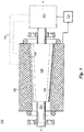
- FIG. 1 a partial view of an exemplary embodiment of an electrical machine in accordance with the disclosure is shown in Fig. 1 and is designated generally by reference character 100.
- FIG. 2 Other embodiments of electrical machines in accordance with the disclosure, or aspects thereof, are provided in Fig. 2 , as will be described.
- the systems and methods described herein can be used for improved electrical machine operation.
- An electrical machine system 100 includes a conical stator 102, e.g., having a conical inward facing surface, defining a rotary axis A and a conical rotor 104, e.g., having a conical outward facing surface opposed to the conical surface of the stator 102.
- a conical gap 106 is defined between the conical surfaces of stator 102 and rotor 104 about the rotary axis A.
- An actuator 108 is operatively connected to rotor 104 for relative linear motion along the rotary axis A of the stator 102 and rotor 104 to change the width of conical gap 106. It is contemplated that the gap 106 can be substantially axisymmetric, i.e., non-eccentric.
- the actuator 108 provides relative linear motion along axis A between a first position for maximal conical gap 106, shown in Fig. 1 , and a second position for minimal conical gap 106, shown in Fig. 2 .
- first and second positions the full axial length of one of the rotor 104 or stator 102 is axially within the axial length of the other.
- Rotor 104 is radially within the stator 102.
- the stator 102 is longer in the axial direction of axis A than the rotor 104, so in both the first and second positions the full axial length of the rotor 104 is axially within the axial length of the stator 102 along axis A.
- a shaft 112 is operatively connected for common rotation with the rotor 104, wherein the actuator 108 is operatively connected to drive the shaft 112 back and forth along the rotary axis A thereby driving the rotor 104 relative to the stator 102 axially to vary the gap 106.
- the actuator moves the rotor 104 relative to the stator 102
- the relative motion can also be achieved with an actuator moving stator 102 instead (e.g., connecting through connection 110 shown in broken lines in Fig. 1 ), or both rotor 104 and stator 104 may be actuated without departing from the scope of this disclosure.
- stator 102 While shown in the exemplary context of having the stator 102 longer than the rotor 104 in the axial direction, it is also contemplated that in embodiments the rotor 104 is longer in the axial direction than the stator 120. For example, if the length of the stator 102 were limited to between the vertical dashed lines in Fig. 2 , in both the first and second positions the full axial length of the stator 102 would be axially within the axial length of the rotor 104.
- the rotor 104 and stator 102 can be configured to operate as a generator, e.g., a permanent magnet generator, wherein the system includes a controller 114 operatively connected to sense input including at least one of generator rotational speed, generator winding current, or output voltage from the generator (as indicated by the arrow into the controller 114) and to control the actuator 108 to adjust the gap 106 based on the input, as indicated by the arrow out of controller 114.
- a generator e.g., a permanent magnet generator
- the system includes a controller 114 operatively connected to sense input including at least one of generator rotational speed, generator winding current, or output voltage from the generator (as indicated by the arrow into the controller 114) and to control the actuator 108 to adjust the gap 106 based on the input, as indicated by the arrow out of controller 114.
- the rotor 104 and stator 102 can be configured to operate as a motor, wherein the controller 114 is operatively connected to sense input including at least one of back-emf voltage from the motor, current supplied to the motor windings, or rotor speed and to control the actuator 108 to adjust the gap 106 based on the input.
- controller 114 can be configured to operate rotor 104 and stator 102 as a motor/generator by switching modes between a generating mode and a motoring mode, as in a starter motor/generator for aerospace applications, for example.
- a method of controlling an electrical machine includes axially moving a conical rotor, e.g. rotor 104, relative to a conical stator, e.g., stator 102, wherein there is a conical gap, e.g., gap 106 separates between the rotor and stator, wherein rotor and stator move relative to one another between a first position maximizing the gap and a second position minimizing the gap.
- a conical gap e.g., gap 106
- Axially moving the conical rotor relative to a conical stator can include operating the rotor and stator as a generator and the method can include controlling the gap to provide a constant output voltage from the generator across a range of speed. It is also contemplated that axially moving the conical rotor relative to a conical stator can include operating the rotor and stator as a generator, wherein the method includes controlling the gap to provide a constant output voltage from the generator across a range of loads. In generator mode, the method can also include controlling the gap in response to a fault in the generator and/or loads powered by the generator to reduce the energy feeding the fault. Controlling the gap in response to a fault can include reducing the gap to a point that the rotor touches down on the stator. This quickly brings the generator to a stop and concentrates the fault energy between the inner diameter of the stator and the rotor which is generally designed to contain such a fault rather than in the area of the actual fault which may not be designed to handle the energy.
- Axially moving the conical rotor relative to a conical stator can include operating the rotor and stator as a motor, wherein the method includes controlling the gap to increase motor speed by reducing back-emf voltage with reduced non-torque producing current relative to what would be required if the gap were not increased.
- the method can include increasing the gap while the rotor accelerates or decelerates through one or more critical speeds to reduce likelihood of rotor touchdown.
Landscapes
- Engineering & Computer Science (AREA)
- Power Engineering (AREA)
- Microelectronics & Electronic Packaging (AREA)
- Permanent Magnet Type Synchronous Machine (AREA)
Abstract
Description
- The present disclosure relates to electrical machines, and more particularly to electrical machines such as used in aerospace and other applications.
- Controlling output voltage of electrical machines, e.g., generators, across a variable speed range or variable loading generally requires complex external controls to boost or reduce the voltage to meet the desired output voltage required. An example is when a generator is driven by a gas turbine engine aboard an aircraft. The voltage tends to vary as the speed of the engine varies during a taxi, take off, climbing, cruising, loitering, descending, landing, and idling. However, the electrical components depending on power from the generator require a relatively constant input voltage. The complex external controls described above are traditionally required to ensure the voltage provided by the generator is constant regardless of the engine speed.
- Such conventional methods and systems have generally been considered satisfactory for their intended purpose. However, there is still a need in the art for improved electrical machines. The present disclosure provides a solution for this need.
- An electrical machine system includes a stator having a conical stator surface defining a rotary axis. A rotor is operatively connected to the stator for rotation relative thereto, wherein the rotor incudes a conical rotor surface. A conical gap is defined between the conical surfaces of the stator and rotor about the rotary axis. An actuator is operatively connected to at least one of the stator and rotor for relative linear motion along the rotary axis of the stator and rotor to change the conical gap, wherein the actuator provides relative linear motion between a first position for a first conical gap width and a second position for a second conical gap width different form the first conical gap width. In both the first and second positions the full axial length of one of the rotor or stator is axially within the axial length of the other.
- The rotor can be radially within the stator. The stator can be longer in the axial direction than the rotor, wherein the actuator provides relative linear motion between a first position for maximal conical gap and a second position for minimal conical gap, wherein in both the first and second positions the full axial length of the rotor is axially within the axial length of the stator. The rotor can be longer in the axial direction than the stator, wherein the actuator provides relative linear motion between a first position for maximal conical gap and a second position for minimal conical gap, wherein in both the first and second positions the full axial length of the stator is axially within the axial length of the rotor.
- A shaft can be operatively connected for common rotation with the rotor, wherein the actuator is operatively connected to drive the shaft back and forth along the rotary axis thereby moving the rotor axially relative to the stator to vary the conical gap. The actuator can be operatively connected to drive the stator back and forth along the rotary axis thereby driving the stator relative to the rotor axially to vary the gap.
- The rotor and stator can be configured to operate as a generator, e.g., a permanent magnet generator, further comprising a controller operatively connected to sense input including at least one of generator rotational speed, generator winding current, or output voltage from the generator and to control the actuator to adjust the gap based on the input. The rotor and stator can be configured to operate as a motor, wherein a controller is operatively connected to sense input including at least one of back-emf voltage from the motor, motor winding current, or rotor speed and to control the actuator to adjust the gap based on the input.
- A method of controlling an electrical machine axially moving a rotor relative to a stator, wherein there is a conical gap separating between a conical surface of the rotor and a conical surface of the stator, wherein rotor and stator move relative to one another between a first position for a first conical gap width and a second position with a second conical gap width different from the first conical gap width, wherein in both the first and second positions the full axial length of one of the rotor or stator is axially within the axial length of the other.
- Axially moving the conical rotor relative to a conical stator can include operating the rotor and stator as a generator, wherein the method includes controlling the gap between the first and second gap widths to provide a constant output voltage from the generator across a range of speed. Axially moving the conical rotor relative to a conical stator can include operating the rotor and stator as a generator, wherein the method includes controlling the gap between the first and second gap widths to provide a constant output voltage from the generator across a range of loads.
- Axially moving the conical rotor relative to a conical stator can include operating the rotor and stator as a generator, wherein the method includes controlling the gap in response to a fault in the generator and/or loads powered by the generator to reduce the energy feeding the fault. Controlling the gap in response to a fault can include reducing the gap to a point that the conical surface of the rotor touches down on the conical surface of the stator to stop relative rotation of the rotor and stator.
- Axially moving the conical rotor relative to a conical stator can include operating the rotor and stator as a motor, wherein the method includes controlling the gap to increase motor speed by reducing back-emf voltage with reduced non-torque producing current relative to what would be required if the gap were not increased. The method can include increasing the gap while the rotor accelerates or decelerates through one or more critical speeds to reduce likelihood of rotor touchdown.
- The stator can be longer in the axial direction than the rotor, wherein an actuator provides relative linear motion between a first position for maximal conical gap and a second position for minimal conical gap, wherein in both the first and second positions the full axial length of the rotor is axially within the axial length of the stator. The rotor can be longer in the axial direction than the stator, wherein an actuator provides relative linear motion between a first position for maximal conical gap and a second position for minimal conical gap, wherein in both the first and second positions the full axial length of the stator is axially within the axial length of the rotor.
- The rotor and stator can be configured to operate as a generator, wherein the method includes using a controller operatively connected to sense input including at least one of generator rotational speed, generator winding current, or output voltage from the generator to control the actuator to adjust the gap based on the input.
- The rotor and stator can be configured to operate as a motor, wherein the method includes using a controller operatively connected to sense input including at least one of back-emf voltage from the motor, motor winding current, or rotor speed to control the actuator to adjust the gap based on the input.
- These and other features of the systems and methods of the subject disclosure will become more readily apparent to those skilled in the art from the following detailed description of the preferred embodiments taken in conjunction with the drawings.
- So that those skilled in the art to which the subject disclosure appertains will readily understand how to make and use the devices and methods of the subject disclosure without undue experimentation, preferred embodiments thereof will be described in detail herein below with reference to certain figures, wherein:
-
Fig. 1 is a schematic cross-sectional side elevation view of an exemplary embodiment of an electrical machine constructed in accordance with the present disclosure, showing the shaft and rotor in a first position; and -
Fig. 2 is a schematic cross-sectional side elevation view of the electrical machine ofFig. 1 , showing the shaft and rotor in a second position with a smaller gap between the rotor and stator than in the first position shown inFig. 1 . - Reference will now be made to the drawings wherein like reference numerals identify similar structural features or aspects of the subject disclosure. For purposes of explanation and illustration, and not limitation, a partial view of an exemplary embodiment of an electrical machine in accordance with the disclosure is shown in
Fig. 1 and is designated generally byreference character 100. Other embodiments of electrical machines in accordance with the disclosure, or aspects thereof, are provided inFig. 2 , as will be described. The systems and methods described herein can be used for improved electrical machine operation. - An
electrical machine system 100 includes aconical stator 102, e.g., having a conical inward facing surface, defining a rotary axis A and aconical rotor 104, e.g., having a conical outward facing surface opposed to the conical surface of thestator 102. Aconical gap 106 is defined between the conical surfaces ofstator 102 androtor 104 about the rotary axis A. Anactuator 108 is operatively connected torotor 104 for relative linear motion along the rotary axis A of thestator 102 androtor 104 to change the width ofconical gap 106. It is contemplated that thegap 106 can be substantially axisymmetric, i.e., non-eccentric. - The
actuator 108 provides relative linear motion along axis A between a first position for maximalconical gap 106, shown inFig. 1 , and a second position for minimalconical gap 106, shown inFig. 2 . In both the first and second positions the full axial length of one of therotor 104 orstator 102 is axially within the axial length of the other.Rotor 104 is radially within thestator 102. Thestator 102 is longer in the axial direction of axis A than therotor 104, so in both the first and second positions the full axial length of therotor 104 is axially within the axial length of thestator 102 along axis A. Ashaft 112 is operatively connected for common rotation with therotor 104, wherein theactuator 108 is operatively connected to drive theshaft 112 back and forth along the rotary axis A thereby driving therotor 104 relative to thestator 102 axially to vary thegap 106. While shown and described with the exemplary embedment wherein the actuator moves therotor 104 relative to thestator 102, those skilled in the art will readily appreciate that the relative motion can also be achieved with anactuator moving stator 102 instead (e.g., connecting throughconnection 110 shown in broken lines inFig. 1 ), or bothrotor 104 andstator 104 may be actuated without departing from the scope of this disclosure. - While shown in the exemplary context of having the
stator 102 longer than therotor 104 in the axial direction, it is also contemplated that in embodiments therotor 104 is longer in the axial direction than the stator 120. For example, if the length of thestator 102 were limited to between the vertical dashed lines inFig. 2 , in both the first and second positions the full axial length of thestator 102 would be axially within the axial length of therotor 104. - The
rotor 104 andstator 102 can be configured to operate as a generator, e.g., a permanent magnet generator, wherein the system includes acontroller 114 operatively connected to sense input including at least one of generator rotational speed, generator winding current, or output voltage from the generator (as indicated by the arrow into the controller 114) and to control theactuator 108 to adjust thegap 106 based on the input, as indicated by the arrow out ofcontroller 114. It is also contemplated that therotor 104 andstator 102 can be configured to operate as a motor, wherein thecontroller 114 is operatively connected to sense input including at least one of back-emf voltage from the motor, current supplied to the motor windings, or rotor speed and to control theactuator 108 to adjust thegap 106 based on the input. Moreover,controller 114 can be configured to operaterotor 104 andstator 102 as a motor/generator by switching modes between a generating mode and a motoring mode, as in a starter motor/generator for aerospace applications, for example. - A method of controlling an electrical machine includes axially moving a conical rotor,
e.g. rotor 104, relative to a conical stator, e.g.,stator 102, wherein there is a conical gap, e.g.,gap 106 separates between the rotor and stator, wherein rotor and stator move relative to one another between a first position maximizing the gap and a second position minimizing the gap. In both the first and second positions the full axial length of one of the rotor or stator is axially within the axial length of the other. - Axially moving the conical rotor relative to a conical stator can include operating the rotor and stator as a generator and the method can include controlling the gap to provide a constant output voltage from the generator across a range of speed. It is also contemplated that axially moving the conical rotor relative to a conical stator can include operating the rotor and stator as a generator, wherein the method includes controlling the gap to provide a constant output voltage from the generator across a range of loads. In generator mode, the method can also include controlling the gap in response to a fault in the generator and/or loads powered by the generator to reduce the energy feeding the fault. Controlling the gap in response to a fault can include reducing the gap to a point that the rotor touches down on the stator. This quickly brings the generator to a stop and concentrates the fault energy between the inner diameter of the stator and the rotor which is generally designed to contain such a fault rather than in the area of the actual fault which may not be designed to handle the energy.
- Axially moving the conical rotor relative to a conical stator can include operating the rotor and stator as a motor, wherein the method includes controlling the gap to increase motor speed by reducing back-emf voltage with reduced non-torque producing current relative to what would be required if the gap were not increased. The method can include increasing the gap while the rotor accelerates or decelerates through one or more critical speeds to reduce likelihood of rotor touchdown.
- The methods and systems of the present disclosure, as described above and shown in the drawings, provide for electrical machines with superior properties including control of the gap between the rotor and the stator. While the apparatus and methods of the subject disclosure have been shown and described with reference to preferred embodiments, those skilled in the art will readily appreciate that changes and/or modifications may be made thereto without departing from the scope of the subject disclosure.
Claims (15)
- An electrical machine system comprising:a stator (102) having a conical stator surface defining a rotary axis;a rotor (104) operatively connected to the stator for rotation relative thereto, wherein the rotor incudes a conical rotor surface, wherein a conical gap is defined between the conical surfaces of the stator and rotor about the rotary axis; andan actuator (108) operatively connected to at least one of the stator (102) and rotor (104) for relative linear motion along the rotary axis of the stator (102) and rotor (104) to change the conical gap (106), wherein the actuator (108) provides relative linear motion between a first position for a first conical gap (106) width and a second position for a second conical gap (106) width different form the first conical gap width, wherein in both the first and second positions the full axial length of one of the rotor or stator is axially within the axial length of the other.
- A system as recited in claim 1, wherein the rotor (104) is radially within the stator.
- A system as recited in claim 2, wherein the stator (102) is longer in the axial direction than the rotor, wherein the actuator provides relative linear motion between a first position for maximal conical gap (106) and a second position for minimal conical gap (106), wherein in both the first and second positions the full axial length of the rotor (104) is axially within the axial length of the stator (102).
- A system as recited in claim 2, further comprising a shaft operatively connected for common rotation with the rotor (104), wherein the actuator (108) is operatively connected to drive the shaft back and forth along the rotary axis thereby moving the rotor axially relative to the stator (102) to vary the conical gap.
- A system as recited in any preceding claim, wherein the rotor (104) is longer in the axial direction than the stator (102), wherein the actuator (108) provides relative linear motion between a first position for maximal conical gap and a second position for minimal conical gap (106), wherein in both the first and second positions the full axial length of the stator is axially within the axial length of the rotor (104).
- A system as recited in any preceding claim, wherein the actuator (108) is operatively connected to drive the stator back and forth along the rotary axis thereby driving the stator relative to the rotor axially to vary the gap.
- A system as recited in any preceding claim, wherein the rotor (104) and stator (102) are configured to operate as a generator, further comprising a controller operatively connected to sense input including at least one of generator rotational speed, generator winding current, or output voltage from the generator and to control the actuator to adjust the gap based on the input, or
wherein the rotor (104) and stator (102) are configured to operate as a motor, further comprising a controller operatively connected to sense input including at least one of back-emf voltage from the motor, motor winding current, or rotor speed and to control the actuator to adjust the gap based on the input. - A system as recited in any preceding claim, wherein the rotor and stator operatively connected as a permanent magnet generator.
- A method of controlling an electrical machine comprising:axially moving a rotor (104) relative to a stator (102), wherein there is a conical gap (106) separating between a conical surface of the rotor (104) and a conical surface of the stator (102), wherein rotor (104) and stator (102) move relative to one another between a first position for a first conical gap width and a second position with a second conical gap width different from the first conical gap width, wherein in both the first and second positions the full axial length of one of the rotor (104) or stator (102) is axially within the axial length of the other.
- A method as recited in claim 9, wherein axially moving the conical rotor (104) relative to a conical stator (102) includes operating the rotor and stator as a generator, further comprising controlling the gap between the first and second gap widths to provide a constant output voltage from the generator across a range of speed, or
wherein axially moving the conical rotor (104) relative to a conical stator includes operating the rotor (104) and stator (102) as a generator, further comprising controlling the gap between the first and second gap widths to provide a constant output voltage from the generator across a range of loads. - A method as recited in claim 9 or 10, wherein axially moving the conical rotor relative to a conical stator includes operating the rotor and stator as a generator, further comprising controlling the gap in response to a fault in the generator and/or loads powered by the generator to reduce the energy feeding the fault, and optionally
wherein controlling the gap (106) in response to a fault includes reducing the gap (106) to a point that the conical surface of the rotor (104) touches down on the conical surface of the stator (102) to stop relative rotation of the rotor (104) and stator (102). - A method as recited in claim 9, 10 or 11, wherein axially moving the conical rotor (104) relative to a conical stator (102) includes operating the rotor (104) and stator (102) as a motor, further comprising controlling the gap (106) to increase motor speed by reducing back-emf voltage with reduced non-torque producing current relative to what would be required if the gap (106) were not increased.
- A method as recited in any of claims 9 to 12, further comprising increasing the gap (106) while the rotor (104) accelerates or decelerates through one or more critical speeds to reduce likelihood of rotor touchdown.
- A method as recited in any of claims 9 to 13, wherein the stator is longer in the axial direction than the rotor (104), wherein an actuator (108) provides relative linear motion between a first position for maximal conical gap and a second position for minimal conical gap (106), wherein in both the first and second positions the full axial length of the rotor (104) is axially within the axial length of the stator (102), or
wherein the rotor (104) is longer in the axial direction than the stator, wherein an actuator (108) provides relative linear motion between a first position for maximal conical gap (106) and a second position for minimal conical gap (106), wherein in both the first and second positions the full axial length of the stator is axially within the axial length of the rotor (104). - A method as recited in any of claims 9 to 14, wherein the rotor and stator are configured to operate as a generator, further comprising using a controller operatively connected to sense input including at least one of generator rotational speed, generator winding current, or output voltage from the generator to control the actuator to adjust the gap (106) based on the input, or
wherein the rotor (104) and stator (102) are configured to operate as a motor, further comprising using a controller operatively connected to sense input including at least one of back-emf voltage from the motor, motor winding current, or rotor speed to control the actuator to adjust the gap (106) based on the input.
Applications Claiming Priority (1)
| Application Number | Priority Date | Filing Date | Title |
|---|---|---|---|
| US15/097,645 US9825510B2 (en) | 2016-04-13 | 2016-04-13 | Variable gap electrical machines |
Publications (1)
| Publication Number | Publication Date |
|---|---|
| EP3232548A1 true EP3232548A1 (en) | 2017-10-18 |
Family
ID=58536881
Family Applications (1)
| Application Number | Title | Priority Date | Filing Date |
|---|---|---|---|
| EP17166014.5A Withdrawn EP3232548A1 (en) | 2016-04-13 | 2017-04-11 | Variable gap electrical machines |
Country Status (2)
| Country | Link |
|---|---|
| US (1) | US9825510B2 (en) |
| EP (1) | EP3232548A1 (en) |
Cited By (1)
| Publication number | Priority date | Publication date | Assignee | Title |
|---|---|---|---|---|
| EP3731384A1 (en) * | 2019-04-23 | 2020-10-28 | SMS Group GmbH | Electric motor and method for operating the same |
Families Citing this family (6)
| Publication number | Priority date | Publication date | Assignee | Title |
|---|---|---|---|---|
| US9991771B2 (en) * | 2013-11-05 | 2018-06-05 | The University Of Maryland, Baltimore County | Active control system for a variable electromotive-force generator with applications to wind turbines, ships, and hybrid vehicles |
| US11894738B2 (en) * | 2020-08-31 | 2024-02-06 | General Electric Company | Turbomachine equipped with an embedded electric machine having a segmented and movable stator |
| FR3118350B1 (en) | 2020-12-17 | 2024-04-05 | Safran | Conical type permanent magnet electric generator for aircraft |
| CN115126554B (en) * | 2021-03-25 | 2025-11-11 | 通用电气公司 | Gas turbine engine equipped with control system using electric machine to manage rotor mode |
| US12388321B2 (en) * | 2021-03-25 | 2025-08-12 | General Electric Company | Gas turbine engine equipped with a control system for management of rotor modes using an electric machine |
| CN112910170A (en) * | 2021-03-25 | 2021-06-04 | 广州小鹏汽车科技有限公司 | Motor, motor control method, vehicle and medium |
Citations (3)
| Publication number | Priority date | Publication date | Assignee | Title |
|---|---|---|---|---|
| JPS5996846A (en) * | 1982-11-25 | 1984-06-04 | Hitachi Seiko Ltd | Low vibration motor |
| US6455975B1 (en) * | 1999-12-03 | 2002-09-24 | Pacific Scientific Electro Kinetics Division | Regulated permanent magnet generator |
| US20130028737A1 (en) * | 2011-07-25 | 2013-01-31 | Sports Art Industrial Co., Ltd. | Adjustable wind turbine generating device |
Family Cites Families (9)
| Publication number | Priority date | Publication date | Assignee | Title |
|---|---|---|---|---|
| US5627419A (en) | 1994-03-31 | 1997-05-06 | United Technologies Corporation | Self-adjusting airgap motor/generator for flywheel system |
| EP0829128B1 (en) * | 1995-05-30 | 2003-07-23 | Vilmos TÖRÖK | A self-starting brushless electric motor |
| US6555941B1 (en) | 2002-03-08 | 2003-04-29 | Dura-Trac Motors, Inc. | Brushless permanent magnet motor or alternator with variable axial rotor/stator alignment to increase speed capability |
| JP4294993B2 (en) | 2002-08-09 | 2009-07-15 | ヤマハ発動機株式会社 | Rotating electric machine |
| GB0614057D0 (en) | 2006-07-14 | 2006-08-23 | Nexxtdrive Ltd | Permanent magnet rotating electric machine |
| EP2237398A1 (en) | 2009-04-03 | 2010-10-06 | Siemens Aktiengesellschaft | Method and arrangement to adjust an air-gap |
| US20100264768A1 (en) | 2009-04-16 | 2010-10-21 | Gm Global Technology Operations, Inc. | Permanent magnet machine with conical stator |
| US20150171721A1 (en) | 2013-12-18 | 2015-06-18 | Hyundai Motor Company | Air gap variable motor |
| WO2015200104A1 (en) | 2014-06-22 | 2015-12-30 | Tutunaru Catalin | Adjustable high torque axial gap electric motor |
-
2016
- 2016-04-13 US US15/097,645 patent/US9825510B2/en not_active Expired - Fee Related
-
2017
- 2017-04-11 EP EP17166014.5A patent/EP3232548A1/en not_active Withdrawn
Patent Citations (3)
| Publication number | Priority date | Publication date | Assignee | Title |
|---|---|---|---|---|
| JPS5996846A (en) * | 1982-11-25 | 1984-06-04 | Hitachi Seiko Ltd | Low vibration motor |
| US6455975B1 (en) * | 1999-12-03 | 2002-09-24 | Pacific Scientific Electro Kinetics Division | Regulated permanent magnet generator |
| US20130028737A1 (en) * | 2011-07-25 | 2013-01-31 | Sports Art Industrial Co., Ltd. | Adjustable wind turbine generating device |
Cited By (1)
| Publication number | Priority date | Publication date | Assignee | Title |
|---|---|---|---|---|
| EP3731384A1 (en) * | 2019-04-23 | 2020-10-28 | SMS Group GmbH | Electric motor and method for operating the same |
Also Published As
| Publication number | Publication date |
|---|---|
| US9825510B2 (en) | 2017-11-21 |
| US20170302138A1 (en) | 2017-10-19 |
Similar Documents
| Publication | Publication Date | Title |
|---|---|---|
| US9825510B2 (en) | Variable gap electrical machines | |
| CN108928493B (en) | Propulsion system for aircraft and method for operating same | |
| EP3375981A1 (en) | Variable speed ac bus powered tail cone boundary layer ingestion thruster | |
| US20100264768A1 (en) | Permanent magnet machine with conical stator | |
| JP6152472B2 (en) | Jet engine assembly and method for generating electricity | |
| US6047104A (en) | Electrical generators and motors in which at steady-state the rotor and its electromagnetic field rotate at selectively different angular speeds | |
| US10050504B2 (en) | Motor structure for variable counter electromotive force | |
| EP1906008A2 (en) | Engine starter-generator optimized for start function | |
| CN102597489A (en) | Turbine engine starter/generator, and method for the control thereof | |
| EP1865172A2 (en) | Method and apparatus for starting a gas turbine engine | |
| CN112550730A (en) | Electric motor for a propeller engine | |
| US10723469B2 (en) | System and method for driving electrically driving a gas turbine engine via a wound field synchronous machine assisted by a PMG | |
| CN103958346B (en) | Rotating mechanical system with contactless actuation and aircraft turbine engine including the same | |
| EP3376663A1 (en) | Generator arrangements and methods of controlling generator arrangements | |
| CN107187594B (en) | All-electric coaxial multi-rotor thrust device based on disc motor and its working method | |
| EP3416279B1 (en) | Electrical machine | |
| US11338906B2 (en) | Propeller system | |
| US10381888B2 (en) | Motor driving method | |
| EP3023331A1 (en) | Aircraft engine assembly and method of generating electric energy for an aircraft power system | |
| US20200224584A1 (en) | Supercharger | |
| JP5164415B2 (en) | Motor drive device | |
| TW201615493A (en) | Driver, mobile device and control method for mobile device | |
| US12212275B2 (en) | Pump actuating device, and associated pumping system, aircraft and fuel supply method | |
| EP3021478B1 (en) | A two stage flux switching machine for an electrical power generation system | |
| EP3240184B1 (en) | Method for implementing a pmg varaible speed constant frequency generating system and a control processor |
Legal Events
| Date | Code | Title | Description |
|---|---|---|---|
| PUAI | Public reference made under article 153(3) epc to a published international application that has entered the european phase |
Free format text: ORIGINAL CODE: 0009012 |
|
| STAA | Information on the status of an ep patent application or granted ep patent |
Free format text: STATUS: THE APPLICATION HAS BEEN PUBLISHED |
|
| AK | Designated contracting states |
Kind code of ref document: A1 Designated state(s): AL AT BE BG CH CY CZ DE DK EE ES FI FR GB GR HR HU IE IS IT LI LT LU LV MC MK MT NL NO PL PT RO RS SE SI SK SM TR |
|
| AX | Request for extension of the european patent |
Extension state: BA ME |
|
| STAA | Information on the status of an ep patent application or granted ep patent |
Free format text: STATUS: REQUEST FOR EXAMINATION WAS MADE |
|
| 17P | Request for examination filed |
Effective date: 20180418 |
|
| RBV | Designated contracting states (corrected) |
Designated state(s): AL AT BE BG CH CY CZ DE DK EE ES FI FR GB GR HR HU IE IS IT LI LT LU LV MC MK MT NL NO PL PT RO RS SE SI SK SM TR |
|
| STAA | Information on the status of an ep patent application or granted ep patent |
Free format text: STATUS: EXAMINATION IS IN PROGRESS |
|
| 17Q | First examination report despatched |
Effective date: 20191119 |
|
| STAA | Information on the status of an ep patent application or granted ep patent |
Free format text: STATUS: THE APPLICATION IS DEEMED TO BE WITHDRAWN |
|
| 18D | Application deemed to be withdrawn |
Effective date: 20211103 |