EP3232530A1 - Cascaded photovoltaic grid-connected inverter, control method and control device for the same - Google Patents
Cascaded photovoltaic grid-connected inverter, control method and control device for the same Download PDFInfo
- Publication number
- EP3232530A1 EP3232530A1 EP17162926.4A EP17162926A EP3232530A1 EP 3232530 A1 EP3232530 A1 EP 3232530A1 EP 17162926 A EP17162926 A EP 17162926A EP 3232530 A1 EP3232530 A1 EP 3232530A1
- Authority
- EP
- European Patent Office
- Prior art keywords
- grid
- inverter
- reactive
- voltage
- cascaded photovoltaic
- Prior art date
- Legal status (The legal status is an assumption and is not a legal conclusion. Google has not performed a legal analysis and makes no representation as to the accuracy of the status listed.)
- Granted
Links
Images


Classifications
-
- H—ELECTRICITY
- H02—GENERATION; CONVERSION OR DISTRIBUTION OF ELECTRIC POWER
- H02J—ELECTRIC POWER NETWORKS; CIRCUIT ARRANGEMENTS OR SYSTEMS FOR SUPPLYING OR DISTRIBUTING ELECTRIC POWER; SYSTEMS FOR STORING ELECTRIC ENERGY
- H02J3/00—Circuit arrangements for AC mains or AC distribution networks
- H02J3/38—Arrangements for feeding a single network from two or more generators or sources in parallel; Arrangements for feeding already energised networks from additional generators or sources in parallel
- H02J3/46—Controlling the sharing of generated power between the generators, sources or networks
-
- H—ELECTRICITY
- H02—GENERATION; CONVERSION OR DISTRIBUTION OF ELECTRIC POWER
- H02J—ELECTRIC POWER NETWORKS; CIRCUIT ARRANGEMENTS OR SYSTEMS FOR SUPPLYING OR DISTRIBUTING ELECTRIC POWER; SYSTEMS FOR STORING ELECTRIC ENERGY
- H02J3/00—Circuit arrangements for AC mains or AC distribution networks
- H02J3/12—Arrangements for adjusting voltage in AC networks by changing a characteristic of the network load
- H02J3/16—Arrangements for adjusting voltage in AC networks by changing a characteristic of the network load by adjustment of reactive power
-
- H—ELECTRICITY
- H02—GENERATION; CONVERSION OR DISTRIBUTION OF ELECTRIC POWER
- H02J—ELECTRIC POWER NETWORKS; CIRCUIT ARRANGEMENTS OR SYSTEMS FOR SUPPLYING OR DISTRIBUTING ELECTRIC POWER; SYSTEMS FOR STORING ELECTRIC ENERGY
- H02J3/00—Circuit arrangements for AC mains or AC distribution networks
- H02J3/38—Arrangements for feeding a single network from two or more generators or sources in parallel; Arrangements for feeding already energised networks from additional generators or sources in parallel
-
- H—ELECTRICITY
- H02—GENERATION; CONVERSION OR DISTRIBUTION OF ELECTRIC POWER
- H02J—ELECTRIC POWER NETWORKS; CIRCUIT ARRANGEMENTS OR SYSTEMS FOR SUPPLYING OR DISTRIBUTING ELECTRIC POWER; SYSTEMS FOR STORING ELECTRIC ENERGY
- H02J3/00—Circuit arrangements for AC mains or AC distribution networks
- H02J3/38—Arrangements for feeding a single network from two or more generators or sources in parallel; Arrangements for feeding already energised networks from additional generators or sources in parallel
- H02J3/381—Dispersed generators
-
- H—ELECTRICITY
- H02—GENERATION; CONVERSION OR DISTRIBUTION OF ELECTRIC POWER
- H02M—APPARATUS FOR CONVERSION BETWEEN AC AND AC, BETWEEN AC AND DC, OR BETWEEN DC AND DC, AND FOR USE WITH MAINS OR SIMILAR POWER SUPPLY SYSTEMS; CONVERSION OF DC OR AC INPUT POWER INTO SURGE OUTPUT POWER; CONTROL OR REGULATION THEREOF
- H02M7/00—Conversion of AC power input into DC power output; Conversion of DC power input into AC power output
- H02M7/42—Conversion of DC power input into AC power output without possibility of reversal
- H02M7/44—Conversion of DC power input into AC power output without possibility of reversal by static converters
- H02M7/48—Conversion of DC power input into AC power output without possibility of reversal by static converters using discharge tubes with control electrode or semiconductor devices with control electrode
- H02M7/483—Converters with outputs that each can have more than two voltages levels
- H02M7/49—Combination of the output voltage waveforms of a plurality of converters
-
- H—ELECTRICITY
- H02—GENERATION; CONVERSION OR DISTRIBUTION OF ELECTRIC POWER
- H02S—GENERATION OF ELECTRIC POWER BY CONVERSION OF INFRARED RADIATION, VISIBLE LIGHT OR ULTRAVIOLET LIGHT, e.g. USING PHOTOVOLTAIC [PV] MODULES
- H02S40/00—Components or accessories in combination with PV modules, not provided for in groups H02S10/00 - H02S30/00
- H02S40/30—Electrical components
- H02S40/32—Electrical components comprising DC/AC inverter means associated with the PV module itself, e.g. AC modules
-
- H—ELECTRICITY
- H02—GENERATION; CONVERSION OR DISTRIBUTION OF ELECTRIC POWER
- H02S—GENERATION OF ELECTRIC POWER BY CONVERSION OF INFRARED RADIATION, VISIBLE LIGHT OR ULTRAVIOLET LIGHT, e.g. USING PHOTOVOLTAIC [PV] MODULES
- H02S40/00—Components or accessories in combination with PV modules, not provided for in groups H02S10/00 - H02S30/00
- H02S40/30—Electrical components
- H02S40/36—Electrical components characterised by special electrical interconnection means between two or more PV modules, e.g. electrical module-to-module connection
-
- H—ELECTRICITY
- H10—SEMICONDUCTOR DEVICES; ELECTRIC SOLID-STATE DEVICES NOT OTHERWISE PROVIDED FOR
- H10F—INORGANIC SEMICONDUCTOR DEVICES SENSITIVE TO INFRARED RADIATION, LIGHT, ELECTROMAGNETIC RADIATION OF SHORTER WAVELENGTH OR CORPUSCULAR RADIATION
- H10F19/00—Integrated devices, or assemblies of multiple devices, comprising at least one photovoltaic cell covered by group H10F10/00, e.g. photovoltaic modules
- H10F19/90—Structures for connecting between photovoltaic cells, e.g. interconnections or insulating spacers
- H10F19/902—Structures for connecting between photovoltaic cells, e.g. interconnections or insulating spacers for series or parallel connection of photovoltaic cells
- H10F19/904—Structures for connecting between photovoltaic cells, e.g. interconnections or insulating spacers for series or parallel connection of photovoltaic cells characterised by the shapes of the structures
-
- H—ELECTRICITY
- H02—GENERATION; CONVERSION OR DISTRIBUTION OF ELECTRIC POWER
- H02J—ELECTRIC POWER NETWORKS; CIRCUIT ARRANGEMENTS OR SYSTEMS FOR SUPPLYING OR DISTRIBUTING ELECTRIC POWER; SYSTEMS FOR STORING ELECTRIC ENERGY
- H02J2101/00—Supply or distribution of decentralised, dispersed or local electric power generation
- H02J2101/20—Dispersed power generation using renewable energy sources
- H02J2101/22—Solar energy
- H02J2101/24—Photovoltaics
-
- H—ELECTRICITY
- H02—GENERATION; CONVERSION OR DISTRIBUTION OF ELECTRIC POWER
- H02J—ELECTRIC POWER NETWORKS; CIRCUIT ARRANGEMENTS OR SYSTEMS FOR SUPPLYING OR DISTRIBUTING ELECTRIC POWER; SYSTEMS FOR STORING ELECTRIC ENERGY
- H02J3/00—Circuit arrangements for AC mains or AC distribution networks
- H02J3/001—Arrangements for handling faults or abnormalities, e.g. emergencies or contingencies
-
- H—ELECTRICITY
- H02—GENERATION; CONVERSION OR DISTRIBUTION OF ELECTRIC POWER
- H02M—APPARATUS FOR CONVERSION BETWEEN AC AND AC, BETWEEN AC AND DC, OR BETWEEN DC AND DC, AND FOR USE WITH MAINS OR SIMILAR POWER SUPPLY SYSTEMS; CONVERSION OF DC OR AC INPUT POWER INTO SURGE OUTPUT POWER; CONTROL OR REGULATION THEREOF
- H02M1/00—Details of apparatus for conversion
- H02M1/0067—Converter structures employing plural converter units, other than for parallel operation of the units on a single load
- H02M1/0077—Plural converter units whose outputs are connected in series
-
- H—ELECTRICITY
- H02—GENERATION; CONVERSION OR DISTRIBUTION OF ELECTRIC POWER
- H02M—APPARATUS FOR CONVERSION BETWEEN AC AND AC, BETWEEN AC AND DC, OR BETWEEN DC AND DC, AND FOR USE WITH MAINS OR SIMILAR POWER SUPPLY SYSTEMS; CONVERSION OF DC OR AC INPUT POWER INTO SURGE OUTPUT POWER; CONTROL OR REGULATION THEREOF
- H02M1/00—Details of apparatus for conversion
- H02M1/42—Circuits or arrangements for compensating for or adjusting power factor in converters or inverters
-
- Y—GENERAL TAGGING OF NEW TECHNOLOGICAL DEVELOPMENTS; GENERAL TAGGING OF CROSS-SECTIONAL TECHNOLOGIES SPANNING OVER SEVERAL SECTIONS OF THE IPC; TECHNICAL SUBJECTS COVERED BY FORMER USPC CROSS-REFERENCE ART COLLECTIONS [XRACs] AND DIGESTS
- Y02—TECHNOLOGIES OR APPLICATIONS FOR MITIGATION OR ADAPTATION AGAINST CLIMATE CHANGE
- Y02B—CLIMATE CHANGE MITIGATION TECHNOLOGIES RELATED TO BUILDINGS, e.g. HOUSING, HOUSE APPLIANCES OR RELATED END-USER APPLICATIONS
- Y02B70/00—Technologies for an efficient end-user side electric power management and consumption
- Y02B70/10—Technologies improving the efficiency by using switched-mode power supplies [SMPS], i.e. efficient power electronics conversion e.g. power factor correction or reduction of losses in power supplies or efficient standby modes
-
- Y—GENERAL TAGGING OF NEW TECHNOLOGICAL DEVELOPMENTS; GENERAL TAGGING OF CROSS-SECTIONAL TECHNOLOGIES SPANNING OVER SEVERAL SECTIONS OF THE IPC; TECHNICAL SUBJECTS COVERED BY FORMER USPC CROSS-REFERENCE ART COLLECTIONS [XRACs] AND DIGESTS
- Y02—TECHNOLOGIES OR APPLICATIONS FOR MITIGATION OR ADAPTATION AGAINST CLIMATE CHANGE
- Y02E—REDUCTION OF GREENHOUSE GAS [GHG] EMISSIONS, RELATED TO ENERGY GENERATION, TRANSMISSION OR DISTRIBUTION
- Y02E10/00—Energy generation through renewable energy sources
- Y02E10/50—Photovoltaic [PV] energy
- Y02E10/56—Power conversion systems, e.g. maximum power point trackers
-
- Y—GENERAL TAGGING OF NEW TECHNOLOGICAL DEVELOPMENTS; GENERAL TAGGING OF CROSS-SECTIONAL TECHNOLOGIES SPANNING OVER SEVERAL SECTIONS OF THE IPC; TECHNICAL SUBJECTS COVERED BY FORMER USPC CROSS-REFERENCE ART COLLECTIONS [XRACs] AND DIGESTS
- Y02—TECHNOLOGIES OR APPLICATIONS FOR MITIGATION OR ADAPTATION AGAINST CLIMATE CHANGE
- Y02E—REDUCTION OF GREENHOUSE GAS [GHG] EMISSIONS, RELATED TO ENERGY GENERATION, TRANSMISSION OR DISTRIBUTION
- Y02E40/00—Technologies for an efficient electrical power generation, transmission or distribution
- Y02E40/30—Reactive power compensation
Definitions
- the present disclosure relates to the field of power electronic technology, and in particular to a cascaded photovoltaic grid-connected inverter, a control method and a control device for the cascaded photovoltaic grid-connected inverter.
- a cascaded photovoltaic grid-connected inverter includes n cascaded inverter units (such as an H-bridge inverter unit), and a topological structure of the cascaded photovoltaic grid-connected inverter is shown in Figure 1 .
- a direct current side of each of the inverter units is connected with an independent photovoltaic array, and alternating current sides of the inverter units are connected in series, and then connected with a power grid through a filtering inductor L.
- a conventional control strategy of the cascaded photovoltaic grid-connected inverter is described as follows.
- Each of the inverter units independently performs maximum power point tracking, stabilizes a direct current bus voltage and uploads a power signal to a total controller.
- the total controller calculates a grid-connected current instruction value based on all power signals, and then achieves an effective control of the current of the power grid by using a PR controller.
- the conventional control strategy is easy to result in an inverter unit over-modulation phenomenon in a case that output active powers between the inverter units are seriously unbalanced.
- an output power of a photovoltaic array corresponding to an inverter unit #1 decreases due to uneven lighting or other factors, an output active power P 1 of the inverter unit #1 is inevitably reduced according to a principle of active power conservation, thereby causing decrease in a grid-connected current effective value.
- output voltages of inverter units #2 to #n are respectively increased in order to maintain the active power conservation of the inverter units #2 to #n.
- the present disclosure provides a cascaded photovoltaic grid-connected inverter, a control method and a control device for the cascaded photovoltaic grid-connected inverter, so that the cascaded photovoltaic grid-connected inverter can still keep grid-connected operation stability in a case that output active powers between various inverter units are seriously unbalanced.
- the injecting the reactive current to the power grid may include: injecting an inductive reactive current to the power grid.
- the injecting the reactive current to the power grid may include: injecting a capacitive reactive current to the power grid.
- the determining whether at least one of the inverter units of the cascaded photovoltaic grid-connected inverter is over-modulated may include: determining whether the grid-connected current effective value is greater than 2 * i dcmin , and determining that at least one of the inverter units of the cascaded photovoltaic grid-connected inverter is over-modulated in a case that the grid-connected current effective value is greater than 2 * i dcmin .
- the injecting the reactive current to the power grid to make the grid-connected current effective value greater than or equal to 2 * i dcmin may include: injecting the reactive current to the power grid to make the grid-connected current effective value equal to 2 * i dcmin .
- a control device for a cascaded photovoltaic grid-connected inverter includes: a determining unit, a reactive injecting unit, a voltage determining unit and a voltage allocating unit.
- the determining unit is configured to determine whether at least one of inverter units of the cascaded photovoltaic grid-connected inverter is over-modulated.
- the reactive injecting unit is configured to inject a reactive current to a power grid to make a grid-connected current effective value greater than or equal to 2 * i dcmin , with i dcmin being a minimum value of output currents of photovoltaic arrays, in a case that the determining unit determines that at least one of the inverter units of the cascaded photovoltaic grid-connected inverter is over-modulated.
- the voltage determining unit is configured to, after an operation of the reactive injecting unit is completed, determine a voltage U 0 required for grid connection for the cascaded photovoltaic grid-connected inverter corresponding to a current grid-connected current effective value.
- the reactive injecting unit may be configured to inject an inductive reactive current to the power grid to make the grid-connected current effective value greater than or equal to 2 * i dcmin , in a case that the determining unit determines that at least one of the inverter units of the cascaded photovoltaic grid-connected inverter is over-modulated; or the reactive injecting unit may be configured to inject a capacitive reactive current to the power grid to make the grid-connected current effective value greater than or equal to 2 * i dcmin , in a case that the determining unit determines that at least one of the inverter units of the cascaded photovoltaic grid-connected inverter is over-modulated.
- the determining unit may be configured to determine whether the grid-connected current effective value is greater than 2 * i dcmin , and determine that at least one of the inverter units of the cascaded photovoltaic grid-connected inverter is over-modulated in a case that the grid-connected current effective value is greater than 2 * i dcmin .
- the reactive injecting unit may be configured to inject the reactive current to the power grid to make the grid-connected current effective value equal to 2 * i dcmin , in a case that the determining unit determines that at least one of the inverter units of the cascaded photovoltaic grid-connected inverter is over-modulated.
- a cascaded photovoltaic grid-connected inverter including the control device for the cascaded photovoltaic grid-connected inverter described above is provided according to the disclosure.
- a control method for a cascaded photovoltaic grid-connected inverter is provided according to an embodiment of the present disclosure, so that the cascaded photovoltaic grid-connected inverter can still keep grid-connected operation stability in a case that output active powers between various inverter units are seriously unbalanced.
- the control method includes steps 101 to 104.
- step 101 it is determined whether at least one of inverter units of the cascaded photovoltaic grid-connected inverter is over-modulated. In a case that there is at least one inverter unit over-modulated, it is necessary to switch a control logic of a total controller, and then step 102 is performed. In a case that none of the inverter units is over-modulated, current control logic of the total controller is not improved, and step 101 is performed again.
- the inverter unit over-modulation phenomenon means that an output voltage peak of an inverter unit exceeds a direct current bus voltage value of the inverter unit, that is, a modulation degree m of the inverter unit is greater than 1.
- the inverter units of the cascaded photovoltaic grid-connected inverter when determining whether at least one of the inverter units of the cascaded photovoltaic grid-connected inverter is over-modulated, it may be determined that at least one of the inverter units of the cascaded photovoltaic grid-connected inverter is over-modulated based on an output voltage peak of at least one of the inverter units exceeds the direct current bus voltage value of the inverter unit. That is, it may be determined that at least one of the inverter units of the cascaded photovoltaic grid-connected inverter is over-modulated based on the modulation degree m of at least one of the inverter units is greater than 1.
- i dcmin is a minimum value of output currents of photovoltaic arrays.
- step 102 in a case that at least one of the inverter units of the cascaded photovoltaic grid-connected inverter is over-modulated, a reactive current is injected to a power grid to make a grid-connected current effective value greater than or equal to 2 * i dcmin , i dcmin is a minimum value of output currents of photovoltaic arrays.
- step 103 it is determined a voltage U 0 required for grid connection for the cascaded photovoltaic grid-connected inverter corresponding to a current grid-connected current effective value.
- a sum of the output reactive voltage of each of the inverter units is equal to U 0p .
- U 0d is an active component of U 0 and U 0p is a reactive component of U 0 .
- P j and U jd are respectively an output active power and an output active voltage of a same inverter unit.
- P 0 is a sum of the output active power of each of the inverter units.
- each inverter unit In a case that there is at least one inverter unit over-modulated, it is necessary to inject a moderate reactive current to the power grid.
- a modulation degree of each inverter unit may be reduced no matter whether the injected reactive current is an inductive reactive current or a capacitive reactive current, so that the cascaded photovoltaic grid-connected inverter can still keep grid-connected operation stability in a case that output active powers between various inverter units are seriously unbalanced.
- two reactive current injection schemes are described in detail.
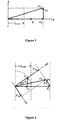
- FIG. 3 a working vector diagram of a cascaded photovoltaic grid-connected inverter before the reactive current is injected to the power grid is shown in Figure 3 .
- a grid voltage vector U s is in a same phase with a grid-connected current vector I s (a module value of each vector in the specification refers to an effective value).
- a filtering inductor voltage vector U L leads the grid-connected current vector I s by 90° in phase.
- a dq coordinate system is established by taking I s as a d axis, U s and U L are an active component and a reactive component of U 0 respectively.
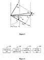
- FIG. 4 A working vector diagram of a cascaded photovoltaic grid-connected inverter after the inductive reactive current is injected to the power grid is shown in Figure 4 , and a drawing process of Figure 4 is analyzed hereinafter.
- FIG. 5 A working vector diagram of a cascaded photovoltaic grid-connected inverter after the capacitive reactive current is injected to the power grid is shown in Figure 5 , and a drawing process of Figure 5 is analyzed hereinafter.
- U jd P j /P 0 * U 0d
- the output active voltage required to be allocated to the each inverter unit will be reduced.
- a control device for a cascaded photovoltaic grid-connected inverter is provided according to an embodiment of the present disclosure, so that the cascaded photovoltaic grid-connected inverter can still keep grid-connected operation stability in a case that output active powers between various inverter units are seriously unbalanced.
- the control device includes a determining unit 100, a reactive injecting unit 200, a voltage determining unit 300 and a voltage allocating unit 400.
- the determining unit 100 is configured to determine whether at least one of inverter units of the cascaded photovoltaic grid-connected inverter is over-modulated.
- the reactive injecting unit 200 is configured to inject a reactive current to a power grid to make a grid-connected current effective value greater than or equal to 2 * i dcmin , with i dcmin being a minimum value of output currents of photovoltaic arrays, in a case that the determining unit 100 determines that at least one of the inverter units of the cascaded photovoltaic grid-connected inverter is over-modulated.
- the voltage determining unit 300 is configured to, after an operation of the reactive injecting unit 200 is completed, determine a voltage U 0 required for grid connection for the cascaded photovoltaic grid-connected inverter corresponding to a current grid-connected current effective value.
- the reactive injecting unit 200 is configured to inject an inductive reactive current to the power grid to make the grid-connected current effective value greater than or equal to 2 * i dcmin , in a case that the determining unit 100 determines that at least one of the inverter units of the cascaded photovoltaic grid-connected inverter is over-modulated.
- the reactive injecting unit 200 is configured to inject a capacitive reactive current to the power grid to make the grid-connected current effective value greater than or equal to 2 * i dcmin , in a case that the determining unit 100 determines that at least one of the inverter units of the cascaded photovoltaic grid-connected inverter is over-modulated.
- the determining unit 100 is configured to determine whether the grid-connected current effective value is greater than 2 * i dcmin , and determine that at least one of the inverter units of the cascaded photovoltaic grid-connected inverter is over-modulated in a case that the grid-connected current effective value is greater than 2 * i dcmin .
- the reactive injecting unit 200 is configured to inject the reactive current to the power grid to make the grid-connected current effective value equal to 2 * i dcmin , in a case that the determining unit determines that at least one of the inverter units of the cascaded photovoltaic grid-connected inverter is over-modulated.
- cascaded photovoltaic grid-connected inverter including the control device for the cascaded photovoltaic grid-connected inverter described above.
Landscapes
- Engineering & Computer Science (AREA)
- Power Engineering (AREA)
- Inverter Devices (AREA)
- Supply And Distribution Of Alternating Current (AREA)
- Control Of Electrical Variables (AREA)
Abstract

Description
- The present disclosure relates to the field of power electronic technology, and in particular to a cascaded photovoltaic grid-connected inverter, a control method and a control device for the cascaded photovoltaic grid-connected inverter.
- A cascaded photovoltaic grid-connected inverter includes n cascaded inverter units (such as an H-bridge inverter unit), and a topological structure of the cascaded photovoltaic grid-connected inverter is shown in
Figure 1 . A direct current side of each of the inverter units is connected with an independent photovoltaic array, and alternating current sides of the inverter units are connected in series, and then connected with a power grid through a filtering inductor L. - A conventional control strategy of the cascaded photovoltaic grid-connected inverter is described as follows. Each of the inverter units independently performs maximum power point tracking, stabilizes a direct current bus voltage and uploads a power signal to a total controller. The total controller calculates a grid-connected current instruction value based on all power signals, and then achieves an effective control of the current of the power grid by using a PR controller.
- However, the conventional control strategy is easy to result in an inverter unit over-modulation phenomenon in a case that output active powers between the inverter units are seriously unbalanced. For example, when an output power of a photovoltaic array corresponding to an
inverter unit # 1 decreases due to uneven lighting or other factors, an output active power P1 of theinverter unit # 1 is inevitably reduced according to a principle of active power conservation, thereby causing decrease in a grid-connected current effective value. After the grid-connected current effective value is decreased, output voltages ofinverter units # 2 to #n are respectively increased in order to maintain the active power conservation of theinverter units # 2 to #n. In a case that an output voltage of a certain inverter unit exceeds a direct current bus voltage of the inverter unit (that is, a modulation degree of the inverter unit is greater than 1), an over-modulation phenomenon occurs in the invert unit, thereby resulting in a negative impact on the grid-connected operation stability of the cascaded photovoltaic grid-connected inverter. - In a view of the above, the present disclosure provides a cascaded photovoltaic grid-connected inverter, a control method and a control device for the cascaded photovoltaic grid-connected inverter, so that the cascaded photovoltaic grid-connected inverter can still keep grid-connected operation stability in a case that output active powers between various inverter units are seriously unbalanced.
- A control method for a cascaded photovoltaic grid-connected inverter is provided according to the disclosure. The control method includes: determining whether at least one of inverter units of the cascaded photovoltaic grid-connected inverter is over-modulated; injecting a reactive current to a power grid to make a grid-connected current effective value greater than or equal to

- The injecting the reactive current to the power grid may include: injecting an inductive reactive current to the power grid.
- The injecting the reactive current to the power grid may include: injecting a capacitive reactive current to the power grid.
- The determining whether at least one of the inverter units of the cascaded photovoltaic grid-connected inverter is over-modulated may include: determining whether the grid-connected current effective value is greater than


- The injecting the reactive current to the power grid to make the grid-connected current effective value greater than or equal to


- A control device for a cascaded photovoltaic grid-connected inverter is provided according to the disclosure. The control device includes: a determining unit, a reactive injecting unit, a voltage determining unit and a voltage allocating unit. The determining unit is configured to determine whether at least one of inverter units of the cascaded photovoltaic grid-connected inverter is over-modulated. The reactive injecting unit is configured to inject a reactive current to a power grid to make a grid-connected current effective value greater than or equal to

- The reactive injecting unit may be configured to inject an inductive reactive current to the power grid to make the grid-connected current effective value greater than or equal to


- The determining unit may be configured to determine whether the grid-connected current effective value is greater than

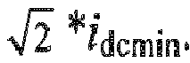
- The reactive injecting unit may be configured to inject the reactive current to the power grid to make the grid-connected current effective value equal to

- A cascaded photovoltaic grid-connected inverter including the control device for the cascaded photovoltaic grid-connected inverter described above is provided according to the disclosure.
- As can be seen from the above technical solutions, when an inverter unit is over-modulated, a moderate reactive current is injected to the power grid. Since an active voltage needed to be outputted by each inverter unit is decreased after the reactive current is injected, a larger output reactive voltage is allocated to an inverter unit of which an output active voltage is smaller, and a smaller output reactive voltage is allocated to an inverter unit of which an output active voltage is larger, so that a modulation degree of each inverter unit is not greater than 1, thereby maintaining the grid-connected operation stability of the cascaded photovoltaic grid-connected inverter.
- The accompany drawings used in the description of the embodiments or the conventional technology are described briefly as follows, so that the technical solutions according to the embodiments in the present disclosure or according to the conventional technology become clearer. It is apparent that the accompany drawings in the following description show only some embodiments of the present disclosure. For those skilled in the art, other accompany drawings may be obtained according to these accompany drawings without any creative work.
-
Figure 1 is a schematic structural diagram of a cascaded photovoltaic grid-connected inverter disclosed in the conventional art; -
Figure 2 is a flow chart of a control method for a cascaded photovoltaic grid-connected inverter according to an embodiment of the disclosure; -
Figure 3 is a working vector diagram of a cascaded photovoltaic grid-connected inverter under a conventional control strategy; -
Figure 4 is a working vector diagram of a cascaded photovoltaic grid-connected inverter after an inductive reactive current is injected to a power grid; -
Figure 5 is a working vector diagram of a cascaded photovoltaic grid-connected inverter after a capacitive reactive current is injected to a power grid; and -
Figure 6 is a schematic structural diagram of a control device for a cascaded photovoltaic grid-connected inverter according to an embodiment of the disclosure. - The technical solution according to the embodiments of the present disclosure will be described clearly and completely as follows in conjunction with the accompany drawings in the embodiments of the present disclosure. It is apparent that the described embodiments are only a part of the embodiments according to the present disclosure. All the other embodiments obtained by those skilled in the art based on the embodiments in the present disclosure without any creative work belong to the protection scope of the present disclosure.
- Referring to
Figure 2 , a control method for a cascaded photovoltaic grid-connected inverter is provided according to an embodiment of the present disclosure, so that the cascaded photovoltaic grid-connected inverter can still keep grid-connected operation stability in a case that output active powers between various inverter units are seriously unbalanced. The control method includessteps 101 to 104. - In
step 101, it is determined whether at least one of inverter units of the cascaded photovoltaic grid-connected inverter is over-modulated. In a case that there is at least one inverter unit over-modulated, it is necessary to switch a control logic of a total controller, and thenstep 102 is performed. In a case that none of the inverter units is over-modulated, current control logic of the total controller is not improved, andstep 101 is performed again. - In a case that the output active powers between the inverter units are seriously unbalanced, it is easy to result in an inverter unit over-modulation phenomenon. The inverter unit over-modulation phenomenon means that an output voltage peak of an inverter unit exceeds a direct current bus voltage value of the inverter unit, that is, a modulation degree m of the inverter unit is greater than 1. Correspondingly, when determining whether at least one of the inverter units of the cascaded photovoltaic grid-connected inverter is over-modulated, it may be determined that at least one of the inverter units of the cascaded photovoltaic grid-connected inverter is over-modulated based on an output voltage peak of at least one of the inverter units exceeds the direct current bus voltage value of the inverter unit. That is, it may be determined that at least one of the inverter units of the cascaded photovoltaic grid-connected inverter is over-modulated based on the modulation degree m of at least one of the inverter units is greater than 1.
- In addition, it may be determined that at least one of the inverter units of the cascaded photovoltaic grid-connected inverter is over-modulated based on a grid-connected current effective value


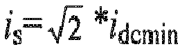
inverter units # 1 to #n (that is, a minimum value of output currents of photovoltaic arrays), it is determined that at least one of the inverter units of the cascaded photovoltaic grid-connected inverter is over-modulated. - In
step 102, in a case that at least one of the inverter units of the cascaded photovoltaic grid-connected inverter is over-modulated, a reactive current is injected to a power grid to make a grid-connected current effective value greater than or equal to
- In
step 103, it is determined a voltage U 0 required for grid connection for the cascaded photovoltaic grid-connected inverter corresponding to a current grid-connected current effective value. - In
step 104, an output active voltage of each of the inverter units is adjusted according to U jd=P j/P0*U 0d, and an output reactive voltage of each of the inverter units is adjusted in a case that none of the inverter units is over-modulated. A sum of the output reactive voltage of each of the inverter units is equal to U 0p. U 0d is an active component of U 0 and U 0p is a reactive component of U 0. P j and U jd are respectively an output active power and an output active voltage of a same inverter unit. And P 0 is a sum of the output active power of each of the inverter units. - In a case that there is at least one inverter unit over-modulated, it is necessary to inject a moderate reactive current to the power grid. A modulation degree of each inverter unit may be reduced no matter whether the injected reactive current is an inductive reactive current or a capacitive reactive current, so that the cascaded photovoltaic grid-connected inverter can still keep grid-connected operation stability in a case that output active powers between various inverter units are seriously unbalanced. Hereinafter, two reactive current injection schemes are described in detail.
- First, a working vector diagram of a cascaded photovoltaic grid-connected inverter before the reactive current is injected to the power grid is shown in
Figure 3 . A grid voltage vector U s is in a same phase with a grid-connected current vector I s (a module value of each vector in the specification refers to an effective value). A filtering inductor voltage vector U L leads the grid-connected current vector I s by 90° in phase. A vector of the voltage required for grid connection of the cascaded photovoltaic grid-connected inverter is U 0=U s+U L. A dq coordinate system is established by taking I s as a d axis, U s and U L are an active component and a reactive component of U 0 respectively. In a case that the grid-connected current effective value i s is less than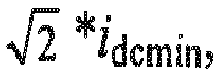

- A working vector diagram of a cascaded photovoltaic grid-connected inverter after the inductive reactive current is injected to the power grid is shown in
Figure 4 , and a drawing process ofFigure 4 is analyzed hereinafter. - (1) The grid voltage vector U s is determined. Before and after the inductive reactive current is injected to the power grid, an amplitude and a direction of the grid voltage vector U s remain the same.
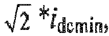
- (2) The grid voltage vector I s is determined. The inductive reactive current is injected to the power grid to make a module value of the grid-connected current vector I s greater than or equal to


- (3) The filtering inductor voltage vector U L is determined. The filtering inductor voltage vector U L leads I s by 90°in phase, and after the grid voltage vector I s is known, a module value of U L may be calculated according to an inductor voltage formula.
- (4) The vector U 0 of the voltage required for grid connection of the cascaded photovoltaic grid-connected inverter is U 0=U s+U L. The dq coordinate system is established by taking I s as a d axis, an active component U 0d and a reactive component U 0p of U 0 in the dq coordinate system may be obtained. The total controller allocates the output active voltage of each inverter unit according to U jd=P j/P 0*U 0d, a sum of output active voltages of all the inverter units is equal to U 0d. In addition, an output reactive voltage of the each inverter unit is assigned in a condition of ensuring that none of the inverter units is over-modulated, and a sum of output reactive voltages of all the inverter units is equal to U jp.
- A working vector diagram of a cascaded photovoltaic grid-connected inverter after the capacitive reactive current is injected to the power grid is shown in
Figure 5 , and a drawing process ofFigure 5 is analyzed hereinafter. - (1) The grid voltage vector U s is determined. Before and after the capacitive reactive current is injected to the power grid, an amplitude and a direction of the grid voltage vector U s remain the same.
- (2) The grid voltage vector I s is determined. The capacitive reactive current is injected to the power grid to make a module value of the grid-connected current vector I s greater than or equal to

- (3) The filtering inductor voltage vector U L is determined. The filtering inductor voltage vector U L leads I s by 90°in phase, and a module value of U L may be calculated based on grid voltage vector I s.
- (4) The vector U 0 of the voltage required for grid connection of the cascaded photovoltaic grid-connected inverter is U 0=U s+U L. The dq coordinate system is established by taking I s as a d axis, an active component U 0d and a reactive component U 0p of U 0 in the dq coordinate system may be obtained. The total controller allocates the output active voltage of each inverter unit according to U jd=P j/P 0*U 0d, a sum of output active voltages of all the inverter units is equal to U 0d. In addition, an output reactive voltage of the each inverter unit is assigned in a condition of ensuring that none of the inverter units is over-modulated, and a sum of output reactive voltages of all the inverter units is equal to U jp.
- As can be seen by analyzing contents of 1) and 2), the total controller reallocates the output active voltage of the each inverter unit according to U jd=P j/P0*U 0d, whether the inductive reactive current or the capacitive reactive current is injected. Referring to
Figure 3 to Figure 5 , it can be found that, since a model value of U 0d after the inductive (or capacitive) reactive current is injected is significantly reduced compared with a model value of U s before the inductive (or capacitive) reactive current is injected, the output active voltage required to be allocated to the each inverter unit will be reduced. And allocation of U 0p is more flexible, a larger output reactive voltage is allocated to an inverter unit of which an output active voltage is smaller, and a smaller output reactive voltage is allocated to an inverter unit of which an output active voltage is larger, so that a module value of a vector sum of an active modulation degree and a reactive modulation degree of the each inverter unit (i.e., the modulation degree of the each inverter unit) is not greater than 1. Therefore, an inverter unit over-modulation phenomenon does not occur, thereby maintaining the grid-connected operation stability of the cascaded photovoltaic grid-connected inverter. - Of course, the more the injected inductive (or capacitive) reactive powers is, the lower the output efficiency of the cascaded photovoltaic grid-connected inverter is, therefore in a condition of ensuring that none of the modulation degrees of all the inverter units is greater than 1, the less the injected reactive power the better. It is known that the more the injected reactive power is, the greater an absolute value of the grid power factor angle is. As can be seen from
Figure 4 andFigure 5 , the absolute value of the grid power factor angle is

- Referring to
Figure 6 , a control device for a cascaded photovoltaic grid-connected inverter is provided according to an embodiment of the present disclosure, so that the cascaded photovoltaic grid-connected inverter can still keep grid-connected operation stability in a case that output active powers between various inverter units are seriously unbalanced. The control device includes a determiningunit 100, areactive injecting unit 200, avoltage determining unit 300 and avoltage allocating unit 400. - The determining
unit 100 is configured to determine whether at least one of inverter units of the cascaded photovoltaic grid-connected inverter is over-modulated. - The
reactive injecting unit 200 is configured to inject a reactive current to a power grid to make a grid-connected current effective value greater than or equal to
unit 100 determines that at least one of the inverter units of the cascaded photovoltaic grid-connected inverter is over-modulated. - The
voltage determining unit 300 is configured to, after an operation of thereactive injecting unit 200 is completed, determine a voltage U 0 required for grid connection for the cascaded photovoltaic grid-connected inverter corresponding to a current grid-connected current effective value. - The
voltage allocating unit 400 is configured to, after thevoltage determining unit 300 determines the voltage U 0, adjust an output active voltage of each of the inverter units according to U jd=P j/P 0*U 0d, and adjust an output reactive voltage of each of the inverter units in a case that none of the inverter units is over-modulated, where a sum of the output reactive voltage of each of the inverter units is equal to U 0p, U 0d is an active component of U 0 and U 0p is a reactive component of U 0, P j and U jd are respectively an output active power and an output active voltage of a same inverter unit, and P 0 is a sum of the output active power of each of the inverter units. - The
reactive injecting unit 200 is configured to inject an inductive reactive current to the power grid to make the grid-connected current effective value greater than or equal to
unit 100 determines that at least one of the inverter units of the cascaded photovoltaic grid-connected inverter is over-modulated. Alternatively, thereactive injecting unit 200 is configured to inject a capacitive reactive current to the power grid to make the grid-connected current effective value greater than or equal to
unit 100 determines that at least one of the inverter units of the cascaded photovoltaic grid-connected inverter is over-modulated. - The determining
unit 100 is configured to determine whether the grid-connected current effective value is greater than

- The
reactive injecting unit 200 is configured to inject the reactive current to the power grid to make the grid-connected current effective value equal to
- In addition, it is provided according to the disclosure a cascaded photovoltaic grid-connected inverter including the control device for the cascaded photovoltaic grid-connected inverter described above.
- In summary, when an inverter unit is over-modulated, a moderate reactive current is injected to the power grid. Since an active voltage needed to be outputted by each inverter unit is decreased after the reactive current is injected, a larger output reactive voltage is allocated to an inverter unit of which an output active voltage is smaller, and a smaller output reactive voltage is allocated to an inverter unit of which an output active voltage is larger, so that a modulation degree of each inverter unit is not greater than 1, thereby maintaining the grid-connected operation stability of the cascaded photovoltaic grid-connected inverter.
- The embodiments of the present disclosure are described herein in a progressive manner, with an emphasis placed on explaining the difference between each embodiment and the other embodiments; hence, for the same or similar parts among the embodiments, they can be referred to from one another. For the device disclosed in the embodiments, the corresponding descriptions are relatively simple because the device corresponds to the method disclosed in the embodiments. The relevant portions may be referred to the description for the method parts.
- The above description of the embodiments disclosed herein enables those skilled in the art to implement or use the present disclosure. Numerous modifications to the embodiments will be apparent to those skilled in the art, and the general principle herein can be implemented in other embodiments without deviation from the spirit or scope of the embodiments of the present disclosure. Therefore, the present disclosure will not be limited to the embodiments described herein, but in accordance with the widest scope consistent with the principle and novel features disclosed herein.
- The present application claims the priority to Chinese Patent Application No.
201610225285.8
Claims (10)
- A control method for a cascaded photovoltaic grid-connected inverter, comprising:determining whether at least one of inverter units of the cascaded photovoltaic grid-connected inverter is over-modulated;injecting a reactive current to a power grid to make a grid-connected current effective value greater than or equal to
 determining a voltage U 0 required for grid connection for the cascaded photovoltaic grid-connected inverter corresponding to a current grid-connected current effective value; andadjusting an output active voltage of each of the inverter units according to U jd=P j lP 0*U 0d, and adjusting an output reactive voltage of each of the inverter units in a case that none of the inverter units is over-modulated, wherein a sum of the output reactive voltage of each of the inverter units is equal to U 0p, U 0d is an active component of U 0 and U 0p is a reactive component of U 0, P j and U jd are respectively an output active power and an output active voltage of a same inverter unit, and P 0 is a sum of the output active power of each of the inverter units.
 - The control method for the cascaded photovoltaic grid-connected inverter according to claim 1, wherein the injecting the reactive current to the power grid comprises: injecting an inductive reactive current to the power grid.
- The control method for the cascaded photovoltaic grid-connected inverter according to claim 1, wherein the injecting the reactive current to the power grid comprises: injecting a capacitive reactive current to the power grid.
- The control method for the cascaded photovoltaic grid-connected inverter according to claim 1, wherein the determining whether at least one of the inverter units of the cascaded photovoltaic grid-connected inverter is over-modulated comprises:determining whether the grid-connected current effective value is greater than


- The control method for the cascaded photovoltaic grid-connected inverter according to claim 1, wherein the injecting the reactive current to the power grid to make the grid-connected current effective value greater than or equal to


- A control device for a cascaded photovoltaic grid-connected inverter, comprising:a determining unit, configured to determine whether at least one of inverter units of the cascaded photovoltaic grid-connected inverter is over-modulated;a reactive injecting unit, configured to inject a reactive current to a power grid to make a grid-connected current effective value greater than or equal to
 a voltage determining unit, configured to, after an operation of the reactive injecting unit is completed, determine a voltage U 0 required for grid connection for the cascaded photovoltaic grid-connected inverter corresponding to a current grid-connected current effective value; anda voltage allocating unit, configured to, after the voltage determining unit determines the voltage U 0, adjust an output active voltage of each of the inverter units according to U jd=P j/P 0 *U 0d, and adjust an output reactive voltage of each of the inverter units in a case that none of the inverter units is over-modulated, wherein a sum of the output reactive voltage of each of the inverter units is equal to U 0p, U 0d is an active component of U 0 and U 0p is a reactive component of U 0, P j and U jd are respectively an output active power and an output active voltage of a same inverter unit, and P 0 is a sum of the output active power of each of the inverter units.
 - The control device for the cascaded photovoltaic grid-connected inverter according to claim 6, wherein
the reactive injecting unit is configured to inject an inductive reactive current to the power grid to make the grid-connected current effective value greater than or equal to
the reactive injecting unit is configured to inject a capacitive reactive current to the power grid to make the grid-connected current effective value greater than or equal to
- The control device for the cascaded photovoltaic grid-connected inverter according to claim 6, wherein the determining unit is configured to determine whether the grid-connected current effective value is greater than


- The control device for the cascaded photovoltaic grid-connected inverter according to claim 6, wherein the reactive injecting unit is configured to inject the reactive current to the power grid to make the grid-connected current effective value equal to

- A cascaded photovoltaic grid-connected inverter, comprising the control device for the cascaded photovoltaic grid-connected inverter according to any one of claims 6 to 9.
Applications Claiming Priority (1)
| Application Number | Priority Date | Filing Date | Title |
|---|---|---|---|
| CN201610225285.8A CN105790302B9 (en) | 2016-04-11 | 2016-04-11 | Cascaded photovoltaic grid-connected inverter and control method and control device thereof |
Publications (2)
| Publication Number | Publication Date |
|---|---|
| EP3232530A1 true EP3232530A1 (en) | 2017-10-18 |
| EP3232530B1 EP3232530B1 (en) | 2020-12-23 |
Family
ID=56396379
Family Applications (1)
| Application Number | Title | Priority Date | Filing Date |
|---|---|---|---|
| EP17162926.4A Active EP3232530B1 (en) | 2016-04-11 | 2017-03-24 | Cascaded photovoltaic grid-connected inverter, control method and control device for the same |
Country Status (4)
| Country | Link |
|---|---|
| US (1) | US10680550B2 (en) |
| EP (1) | EP3232530B1 (en) |
| JP (1) | JP6600841B2 (en) |
| CN (1) | CN105790302B9 (en) |
Cited By (1)
| Publication number | Priority date | Publication date | Assignee | Title |
|---|---|---|---|---|
| DE102020206811A1 (en) | 2020-05-29 | 2021-12-02 | Viessmann Werke Gmbh & Co Kg | Solar module, method and system for generating electrical energy using solar energy and for feeding the generated electrical energy into a power grid |
Families Citing this family (26)
| Publication number | Priority date | Publication date | Assignee | Title |
|---|---|---|---|---|
| EP3080887B2 (en) * | 2013-12-11 | 2023-08-23 | Vestas Wind Systems A/S | A wind power plant, and a method for increasing the reactive power capability of a wind power plant |
| CN106253334B (en) * | 2016-08-19 | 2018-12-28 | 阳光电源股份有限公司 | A kind of Cascade-type photovoltaic grid-connected inverter and its control method and control device |
| CN107370410B (en) * | 2017-07-27 | 2019-09-20 | 阳光电源股份有限公司 | Cascaded H-bridge inverter control method and control device |
| CN107546968A (en) * | 2017-10-10 | 2018-01-05 | 北京东标电子有限公司 | A kind of railway supply harmonic administers voltage-stabilizing system |
| CN107947229B (en) * | 2017-11-28 | 2020-07-07 | 阳光电源股份有限公司 | Control method and device for alternating current cascade photovoltaic power generation system |
| CN107968437B (en) * | 2017-12-27 | 2019-09-20 | 南京工程学院 | A high-permeability photovoltaic access method to prevent overvoltage at the neutral point of the main transformer |
| CN108233415B (en) * | 2018-01-15 | 2020-06-23 | 合肥工业大学 | Two-stage photovoltaic inverter virtual synchronous generator control method |
| CN108288921B (en) * | 2018-01-23 | 2020-05-22 | 阳光电源股份有限公司 | A cascaded inverter control system and control method |
| CN108321814B (en) * | 2018-02-23 | 2021-03-02 | 河南理工大学 | A zero-sequence voltage injection method for reducing the capacitance of DC side capacitors |
| CN108493994B (en) * | 2018-03-28 | 2021-08-20 | 深圳市伊力科电源有限公司 | Feed network type inverter power supply control method and device |
| CN108777497B (en) * | 2018-07-27 | 2020-09-15 | 国网宁夏电力有限公司 | A two-stage photovoltaic power generation actively participates in grid frequency regulation control strategy |
| CN109066699B (en) * | 2018-09-04 | 2021-11-02 | 兰州理工大学 | A method for judging the influence of overmodulation on the voltage of micro-source inverters in series with micro-grid |
| CN110034580B (en) * | 2019-04-15 | 2022-12-09 | 湖南工业大学 | Proportional down-order resonant control strategy method for inverters under unbalanced grid voltage |
| JP6656502B1 (en) * | 2019-07-23 | 2020-03-04 | 三菱電機株式会社 | Power converter |
| CN110957757B (en) * | 2019-10-31 | 2022-08-12 | 合肥工业大学 | Control method of independent DC bus open-winding dual-inverter photovoltaic power generation system |
| CN110880783B (en) * | 2019-11-05 | 2022-07-01 | 中国电力科学研究院有限公司 | Control method and system for photovoltaic power station group string type inverter |
| KR20220157412A (en) * | 2020-03-11 | 2022-11-29 | 써드 이퀘이션 리미티드 | Power converters for photovoltaic energy sources |
| CN112017072B (en) * | 2020-08-26 | 2024-05-14 | 阳光电源(上海)有限公司 | Photovoltaic system, positioning method of equipment in string, MLPE equipment and sequencing method of MLPE equipment |
| CN112436548B (en) * | 2020-11-17 | 2022-12-13 | 青岛大学 | Photovoltaic power generation system |
| CN112510759B (en) * | 2020-12-07 | 2022-08-02 | 合肥工业大学 | Power unbalance control method of common direct current bus cascade type photovoltaic inverter |
| CN112600399B (en) * | 2020-12-15 | 2022-01-04 | 国网湖北省电力有限公司电力科学研究院 | Cascaded H-bridge type medium-voltage UPS power unit bypass control method |
| CN113315180B (en) * | 2021-06-03 | 2022-03-18 | 浙江大学 | Reactive power distribution method suitable for problem of power imbalance among modules in photovoltaic power generation |
| CN114421472B (en) * | 2022-02-21 | 2024-06-18 | 江苏正瑞信息科技有限公司 | Active power distribution network active and reactive power coordination control method |
| CN115276549B (en) * | 2022-09-30 | 2022-12-27 | 锦浪科技股份有限公司 | PID effect suppression system |
| CN115800792A (en) * | 2022-11-22 | 2023-03-14 | 阳光电源股份有限公司 | Micro inverter, photovoltaic system and control method |
| KR102954832B1 (en) * | 2025-11-10 | 2026-04-21 | 주식회사 에이치티솔루션 | Apparatus for controlling inverter for photovoltaic system |
Family Cites Families (8)
| Publication number | Priority date | Publication date | Assignee | Title |
|---|---|---|---|---|
| JPH05260762A (en) * | 1992-03-16 | 1993-10-08 | Mitsubishi Electric Corp | Inverter device |
| WO1996018937A1 (en) * | 1994-12-14 | 1996-06-20 | Kenetech Windpower, Inc. | Grid connected bi-directional converter including a pwm, dc-dc chopper, and energy storage/supply device |
| EP1870993A1 (en) | 2006-06-22 | 2007-12-26 | ALSTOM Technology Ltd | Method of controlling a three level converter |
| JP4775181B2 (en) | 2006-08-30 | 2011-09-21 | オムロン株式会社 | Isolated operation detection device, isolated operation detection method thereof, and power conditioner incorporating the isolated operation detection device |
| CN104052325B (en) * | 2014-06-05 | 2016-07-06 | 上海交通大学 | The method for designing of the cascade multilevel inverter that voltage distortion minimizes on a large scale |
| CN103997249A (en) * | 2014-06-12 | 2014-08-20 | 国家电网公司 | Method for controlling distributed power grid-connected inverter |
| CN104092245B (en) * | 2014-07-24 | 2017-02-15 | 阳光电源股份有限公司 | Alternating-current bypass single-phase photovoltaic inverter and control method and control device thereof |
| CN105356469A (en) * | 2015-11-19 | 2016-02-24 | 福州大学 | Uniform control method based on harmonic detection and photovoltaic grid-connected instruction synthesis |
-
2016
- 2016-04-11 CN CN201610225285.8A patent/CN105790302B9/en active Active
-
2017
- 2017-03-24 EP EP17162926.4A patent/EP3232530B1/en active Active
- 2017-03-30 US US15/474,022 patent/US10680550B2/en active Active
- 2017-03-30 JP JP2017067792A patent/JP6600841B2/en active Active
Non-Patent Citations (1)
| Title |
|---|
| LIU LIMING ET AL: "Reactive Power Compensation and Optimization Strategy for Grid-Interactive Cascaded Photovoltaic Systems", IEEE TRANSACTIONS ON POWER ELECTRONICS, INSTITUTE OF ELECTRICAL AND ELECTRONICS ENGINEERS, USA, vol. 30, no. 1, 25 June 2014 (2014-06-25), pages 188 - 202, XP011557500, ISSN: 0885-8993, [retrieved on 20140826], DOI: 10.1109/TPEL.2014.2333004 * |
Cited By (1)
| Publication number | Priority date | Publication date | Assignee | Title |
|---|---|---|---|---|
| DE102020206811A1 (en) | 2020-05-29 | 2021-12-02 | Viessmann Werke Gmbh & Co Kg | Solar module, method and system for generating electrical energy using solar energy and for feeding the generated electrical energy into a power grid |
Also Published As
| Publication number | Publication date |
|---|---|
| JP6600841B2 (en) | 2019-11-06 |
| CN105790302B (en) | 2018-02-23 |
| CN105790302A (en) | 2016-07-20 |
| US20170294875A1 (en) | 2017-10-12 |
| US10680550B2 (en) | 2020-06-09 |
| CN105790302B9 (en) | 2018-08-07 |
| JP2017192296A (en) | 2017-10-19 |
| EP3232530B1 (en) | 2020-12-23 |
Similar Documents
| Publication | Publication Date | Title |
|---|---|---|
| US10680550B2 (en) | Cascaded photovoltaic grid-connected inverter, control method and control device for the same | |
| EP3188336B1 (en) | Three-level photovoltaic inverter pulse width modulation method and modulator | |
| EP3082240B1 (en) | Offset voltage generator and method for generating an offset voltage of three-phase inverter | |
| TWI523367B (en) | Control device and method for controlling power conversion unit | |
| US20160190811A1 (en) | Control method and system for photovoltaic inverters whose ac sides are connected in parallel | |
| US11424693B2 (en) | Three-level power conversion device, three-level power conversion device control method, and storage medium | |
| EP3285350B1 (en) | Cascaded photovoltaic grid-connected inverter, control method and control device for the same | |
| EP3082247B1 (en) | Offset voltage generator and method for generating an offset voltage of three-phase inverter | |
| CN104201919B (en) | A kind of electric leakage method of flow control of photovoltaic DC-to-AC converter | |
| US9705419B2 (en) | Control signal generating system and inverter control device thereof for improving grid stability | |
| CN103401452A (en) | VSVPWM (Virtual Space Vector Pulse Width Modulation)-based three-level inverter neutral point potential compensation balance control strategy | |
| EP2879284A2 (en) | Current source power conversion apparatus and current source power conversion method | |
| CN104578886A (en) | Pulse width modulation method for three-level photovoltaic inverter and modulator | |
| EP3836331A1 (en) | Power conversion device | |
| CN110249497B (en) | Regulating method of bus voltage and relative equipment | |
| US10044291B2 (en) | Method and device for modulating a five-level inverter, and photovoltaic system | |
| EP3506474B1 (en) | Single-phase converter control method and apparatus | |
| CN107171352B (en) | Calculation method of flexible DC steady-state operation range in parallel hybrid DC system | |
| CN107425596A (en) | Electronic equipment, control method of electronic device and device | |
| CN104283232B (en) | A kind of for HVDC light system unit dc-voltage balance control method | |
| CN103715875A (en) | Switching frequency adjusting method and device and inverters | |
| EP1923989B1 (en) | Power conversion system and power conversion control method | |
| US9871466B2 (en) | Inverter switching frequency control method and apparatus | |
| CN104038092A (en) | Control method for power balance of hybrid multilevel inverter | |
| CN105958522A (en) | Method of determining converter DC-side power limit under asymmetric AC voltage |
Legal Events
| Date | Code | Title | Description |
|---|---|---|---|
| PUAI | Public reference made under article 153(3) epc to a published international application that has entered the european phase |
Free format text: ORIGINAL CODE: 0009012 |
|
| STAA | Information on the status of an ep patent application or granted ep patent |
Free format text: STATUS: THE APPLICATION HAS BEEN PUBLISHED |
|
| AK | Designated contracting states |
Kind code of ref document: A1 Designated state(s): AL AT BE BG CH CY CZ DE DK EE ES FI FR GB GR HR HU IE IS IT LI LT LU LV MC MK MT NL NO PL PT RO RS SE SI SK SM TR |
|
| AX | Request for extension of the european patent |
Extension state: BA ME |
|
| STAA | Information on the status of an ep patent application or granted ep patent |
Free format text: STATUS: REQUEST FOR EXAMINATION WAS MADE |
|
| 17P | Request for examination filed |
Effective date: 20180418 |
|
| RBV | Designated contracting states (corrected) |
Designated state(s): AL AT BE BG CH CY CZ DE DK EE ES FI FR GB GR HR HU IE IS IT LI LT LU LV MC MK MT NL NO PL PT RO RS SE SI SK SM TR |
|
| GRAP | Despatch of communication of intention to grant a patent |
Free format text: ORIGINAL CODE: EPIDOSNIGR1 |
|
| STAA | Information on the status of an ep patent application or granted ep patent |
Free format text: STATUS: GRANT OF PATENT IS INTENDED |
|
| RIC1 | Information provided on ipc code assigned before grant |
Ipc: H02M 1/42 20070101ALI20191011BHEP Ipc: H02M 7/49 20070101ALI20191011BHEP Ipc: H02M 7/5387 20070101ALI20191011BHEP Ipc: H02J 3/38 20060101AFI20191011BHEP |
|
| INTG | Intention to grant announced |
Effective date: 20191118 |
|
| GRAJ | Information related to disapproval of communication of intention to grant by the applicant or resumption of examination proceedings by the epo deleted |
Free format text: ORIGINAL CODE: EPIDOSDIGR1 |
|
| STAA | Information on the status of an ep patent application or granted ep patent |
Free format text: STATUS: REQUEST FOR EXAMINATION WAS MADE |
|
| STAA | Information on the status of an ep patent application or granted ep patent |
Free format text: STATUS: EXAMINATION IS IN PROGRESS |
|
| INTC | Intention to grant announced (deleted) | ||
| 17Q | First examination report despatched |
Effective date: 20200319 |
|
| GRAJ | Information related to disapproval of communication of intention to grant by the applicant or resumption of examination proceedings by the epo deleted |
Free format text: ORIGINAL CODE: EPIDOSDIGR1 |
|
| GRAP | Despatch of communication of intention to grant a patent |
Free format text: ORIGINAL CODE: EPIDOSNIGR1 |
|
| GRAP | Despatch of communication of intention to grant a patent |
Free format text: ORIGINAL CODE: EPIDOSNIGR1 |
|
| STAA | Information on the status of an ep patent application or granted ep patent |
Free format text: STATUS: GRANT OF PATENT IS INTENDED |
|
| INTG | Intention to grant announced |
Effective date: 20200901 |
|
| GRAS | Grant fee paid |
Free format text: ORIGINAL CODE: EPIDOSNIGR3 |
|
| GRAA | (expected) grant |
Free format text: ORIGINAL CODE: 0009210 |
|
| STAA | Information on the status of an ep patent application or granted ep patent |
Free format text: STATUS: THE PATENT HAS BEEN GRANTED |
|
| AK | Designated contracting states |
Kind code of ref document: B1 Designated state(s): AL AT BE BG CH CY CZ DE DK EE ES FI FR GB GR HR HU IE IS IT LI LT LU LV MC MK MT NL NO PL PT RO RS SE SI SK SM TR |
|
| REG | Reference to a national code |
Ref country code: GB Ref legal event code: FG4D |
|
| REG | Reference to a national code |
Ref country code: DE Ref legal event code: R096 Ref document number: 602017029865 Country of ref document: DE |
|
| REG | Reference to a national code |
Ref country code: AT Ref legal event code: REF Ref document number: 1348656 Country of ref document: AT Kind code of ref document: T Effective date: 20210115 |
|
| REG | Reference to a national code |
Ref country code: IE Ref legal event code: FG4D |
|
| PG25 | Lapsed in a contracting state [announced via postgrant information from national office to epo] |
Ref country code: GR Free format text: LAPSE BECAUSE OF FAILURE TO SUBMIT A TRANSLATION OF THE DESCRIPTION OR TO PAY THE FEE WITHIN THE PRESCRIBED TIME-LIMIT Effective date: 20210324 Ref country code: FI Free format text: LAPSE BECAUSE OF FAILURE TO SUBMIT A TRANSLATION OF THE DESCRIPTION OR TO PAY THE FEE WITHIN THE PRESCRIBED TIME-LIMIT Effective date: 20201223 Ref country code: RS Free format text: LAPSE BECAUSE OF FAILURE TO SUBMIT A TRANSLATION OF THE DESCRIPTION OR TO PAY THE FEE WITHIN THE PRESCRIBED TIME-LIMIT Effective date: 20201223 Ref country code: NO Free format text: LAPSE BECAUSE OF FAILURE TO SUBMIT A TRANSLATION OF THE DESCRIPTION OR TO PAY THE FEE WITHIN THE PRESCRIBED TIME-LIMIT Effective date: 20210323 |
|
| REG | Reference to a national code |
Ref country code: AT Ref legal event code: MK05 Ref document number: 1348656 Country of ref document: AT Kind code of ref document: T Effective date: 20201223 |
|
| REG | Reference to a national code |
Ref country code: NL Ref legal event code: MP Effective date: 20201223 |
|
| PG25 | Lapsed in a contracting state [announced via postgrant information from national office to epo] |
Ref country code: SE Free format text: LAPSE BECAUSE OF FAILURE TO SUBMIT A TRANSLATION OF THE DESCRIPTION OR TO PAY THE FEE WITHIN THE PRESCRIBED TIME-LIMIT Effective date: 20201223 Ref country code: BG Free format text: LAPSE BECAUSE OF FAILURE TO SUBMIT A TRANSLATION OF THE DESCRIPTION OR TO PAY THE FEE WITHIN THE PRESCRIBED TIME-LIMIT Effective date: 20210323 Ref country code: LV Free format text: LAPSE BECAUSE OF FAILURE TO SUBMIT A TRANSLATION OF THE DESCRIPTION OR TO PAY THE FEE WITHIN THE PRESCRIBED TIME-LIMIT Effective date: 20201223 |
|
| PG25 | Lapsed in a contracting state [announced via postgrant information from national office to epo] |
Ref country code: HR Free format text: LAPSE BECAUSE OF FAILURE TO SUBMIT A TRANSLATION OF THE DESCRIPTION OR TO PAY THE FEE WITHIN THE PRESCRIBED TIME-LIMIT Effective date: 20201223 Ref country code: NL Free format text: LAPSE BECAUSE OF FAILURE TO SUBMIT A TRANSLATION OF THE DESCRIPTION OR TO PAY THE FEE WITHIN THE PRESCRIBED TIME-LIMIT Effective date: 20201223 |
|
| REG | Reference to a national code |
Ref country code: LT Ref legal event code: MG9D |
|
| PG25 | Lapsed in a contracting state [announced via postgrant information from national office to epo] |
Ref country code: RO Free format text: LAPSE BECAUSE OF FAILURE TO SUBMIT A TRANSLATION OF THE DESCRIPTION OR TO PAY THE FEE WITHIN THE PRESCRIBED TIME-LIMIT Effective date: 20201223 Ref country code: SK Free format text: LAPSE BECAUSE OF FAILURE TO SUBMIT A TRANSLATION OF THE DESCRIPTION OR TO PAY THE FEE WITHIN THE PRESCRIBED TIME-LIMIT Effective date: 20201223 Ref country code: PT Free format text: LAPSE BECAUSE OF FAILURE TO SUBMIT A TRANSLATION OF THE DESCRIPTION OR TO PAY THE FEE WITHIN THE PRESCRIBED TIME-LIMIT Effective date: 20210423 Ref country code: SM Free format text: LAPSE BECAUSE OF FAILURE TO SUBMIT A TRANSLATION OF THE DESCRIPTION OR TO PAY THE FEE WITHIN THE PRESCRIBED TIME-LIMIT Effective date: 20201223 Ref country code: LT Free format text: LAPSE BECAUSE OF FAILURE TO SUBMIT A TRANSLATION OF THE DESCRIPTION OR TO PAY THE FEE WITHIN THE PRESCRIBED TIME-LIMIT Effective date: 20201223 Ref country code: CZ Free format text: LAPSE BECAUSE OF FAILURE TO SUBMIT A TRANSLATION OF THE DESCRIPTION OR TO PAY THE FEE WITHIN THE PRESCRIBED TIME-LIMIT Effective date: 20201223 Ref country code: EE Free format text: LAPSE BECAUSE OF FAILURE TO SUBMIT A TRANSLATION OF THE DESCRIPTION OR TO PAY THE FEE WITHIN THE PRESCRIBED TIME-LIMIT Effective date: 20201223 |
|
| PG25 | Lapsed in a contracting state [announced via postgrant information from national office to epo] |
Ref country code: PL Free format text: LAPSE BECAUSE OF FAILURE TO SUBMIT A TRANSLATION OF THE DESCRIPTION OR TO PAY THE FEE WITHIN THE PRESCRIBED TIME-LIMIT Effective date: 20201223 Ref country code: AT Free format text: LAPSE BECAUSE OF FAILURE TO SUBMIT A TRANSLATION OF THE DESCRIPTION OR TO PAY THE FEE WITHIN THE PRESCRIBED TIME-LIMIT Effective date: 20201223 |
|
| REG | Reference to a national code |
Ref country code: DE Ref legal event code: R097 Ref document number: 602017029865 Country of ref document: DE |
|
| PG25 | Lapsed in a contracting state [announced via postgrant information from national office to epo] |
Ref country code: IS Free format text: LAPSE BECAUSE OF FAILURE TO SUBMIT A TRANSLATION OF THE DESCRIPTION OR TO PAY THE FEE WITHIN THE PRESCRIBED TIME-LIMIT Effective date: 20210423 |
|
| PG25 | Lapsed in a contracting state [announced via postgrant information from national office to epo] |
Ref country code: AL Free format text: LAPSE BECAUSE OF FAILURE TO SUBMIT A TRANSLATION OF THE DESCRIPTION OR TO PAY THE FEE WITHIN THE PRESCRIBED TIME-LIMIT Effective date: 20201223 Ref country code: IT Free format text: LAPSE BECAUSE OF FAILURE TO SUBMIT A TRANSLATION OF THE DESCRIPTION OR TO PAY THE FEE WITHIN THE PRESCRIBED TIME-LIMIT Effective date: 20201223 Ref country code: MC Free format text: LAPSE BECAUSE OF FAILURE TO SUBMIT A TRANSLATION OF THE DESCRIPTION OR TO PAY THE FEE WITHIN THE PRESCRIBED TIME-LIMIT Effective date: 20201223 |
|
| PLBE | No opposition filed within time limit |
Free format text: ORIGINAL CODE: 0009261 |
|
| REG | Reference to a national code |
Ref country code: CH Ref legal event code: PL |
|
| STAA | Information on the status of an ep patent application or granted ep patent |
Free format text: STATUS: NO OPPOSITION FILED WITHIN TIME LIMIT |
|
| PG25 | Lapsed in a contracting state [announced via postgrant information from national office to epo] |
Ref country code: DK Free format text: LAPSE BECAUSE OF FAILURE TO SUBMIT A TRANSLATION OF THE DESCRIPTION OR TO PAY THE FEE WITHIN THE PRESCRIBED TIME-LIMIT Effective date: 20201223 |
|
| 26N | No opposition filed |
Effective date: 20210924 |
|
| REG | Reference to a national code |
Ref country code: BE Ref legal event code: MM Effective date: 20210331 |
|
| PG25 | Lapsed in a contracting state [announced via postgrant information from national office to epo] |
Ref country code: ES Free format text: LAPSE BECAUSE OF FAILURE TO SUBMIT A TRANSLATION OF THE DESCRIPTION OR TO PAY THE FEE WITHIN THE PRESCRIBED TIME-LIMIT Effective date: 20201223 Ref country code: FR Free format text: LAPSE BECAUSE OF NON-PAYMENT OF DUE FEES Effective date: 20210331 Ref country code: IE Free format text: LAPSE BECAUSE OF NON-PAYMENT OF DUE FEES Effective date: 20210324 Ref country code: CH Free format text: LAPSE BECAUSE OF NON-PAYMENT OF DUE FEES Effective date: 20210331 Ref country code: LI Free format text: LAPSE BECAUSE OF NON-PAYMENT OF DUE FEES Effective date: 20210331 Ref country code: LU Free format text: LAPSE BECAUSE OF NON-PAYMENT OF DUE FEES Effective date: 20210324 |
|
| PG25 | Lapsed in a contracting state [announced via postgrant information from national office to epo] |
Ref country code: SI Free format text: LAPSE BECAUSE OF FAILURE TO SUBMIT A TRANSLATION OF THE DESCRIPTION OR TO PAY THE FEE WITHIN THE PRESCRIBED TIME-LIMIT Effective date: 20201223 |
|
| REG | Reference to a national code |
Ref country code: DE Ref legal event code: R082 Ref document number: 602017029865 Country of ref document: DE Representative=s name: ZACCO LEGAL RECHTSANWALTSGESELLSCHAFT MBH, DE |
|
| PG25 | Lapsed in a contracting state [announced via postgrant information from national office to epo] |
Ref country code: IS Free format text: LAPSE BECAUSE OF FAILURE TO SUBMIT A TRANSLATION OF THE DESCRIPTION OR TO PAY THE FEE WITHIN THE PRESCRIBED TIME-LIMIT Effective date: 20210423 |
|
| PG25 | Lapsed in a contracting state [announced via postgrant information from national office to epo] |
Ref country code: BE Free format text: LAPSE BECAUSE OF NON-PAYMENT OF DUE FEES Effective date: 20210331 |
|
| PG25 | Lapsed in a contracting state [announced via postgrant information from national office to epo] |
Ref country code: HU Free format text: LAPSE BECAUSE OF FAILURE TO SUBMIT A TRANSLATION OF THE DESCRIPTION OR TO PAY THE FEE WITHIN THE PRESCRIBED TIME-LIMIT; INVALID AB INITIO Effective date: 20170324 |
|
| P01 | Opt-out of the competence of the unified patent court (upc) registered |
Effective date: 20230426 |
|
| PG25 | Lapsed in a contracting state [announced via postgrant information from national office to epo] |
Ref country code: CY Free format text: LAPSE BECAUSE OF FAILURE TO SUBMIT A TRANSLATION OF THE DESCRIPTION OR TO PAY THE FEE WITHIN THE PRESCRIBED TIME-LIMIT Effective date: 20201223 |
|
| PG25 | Lapsed in a contracting state [announced via postgrant information from national office to epo] |
Ref country code: MK Free format text: LAPSE BECAUSE OF FAILURE TO SUBMIT A TRANSLATION OF THE DESCRIPTION OR TO PAY THE FEE WITHIN THE PRESCRIBED TIME-LIMIT Effective date: 20201223 |
|
| PG25 | Lapsed in a contracting state [announced via postgrant information from national office to epo] |
Ref country code: MT Free format text: LAPSE BECAUSE OF FAILURE TO SUBMIT A TRANSLATION OF THE DESCRIPTION OR TO PAY THE FEE WITHIN THE PRESCRIBED TIME-LIMIT Effective date: 20201223 |
|
| REG | Reference to a national code |
Ref country code: DE Ref legal event code: R082 Ref document number: 602017029865 Country of ref document: DE |
|
| PG25 | Lapsed in a contracting state [announced via postgrant information from national office to epo] |
Ref country code: TR Free format text: LAPSE BECAUSE OF FAILURE TO SUBMIT A TRANSLATION OF THE DESCRIPTION OR TO PAY THE FEE WITHIN THE PRESCRIBED TIME-LIMIT Effective date: 20201223 |
|
| PGFP | Annual fee paid to national office [announced via postgrant information from national office to epo] |
Ref country code: GB Payment date: 20260323 Year of fee payment: 10 |
|
| PGFP | Annual fee paid to national office [announced via postgrant information from national office to epo] |
Ref country code: DE Payment date: 20260313 Year of fee payment: 10 |