EP3232425A1 - Flexible screen protection structure and manufacturing method therefor, and flexible display screen applying flexible screen protection structure - Google Patents
Flexible screen protection structure and manufacturing method therefor, and flexible display screen applying flexible screen protection structure Download PDFInfo
- Publication number
- EP3232425A1 EP3232425A1 EP14907752.1A EP14907752A EP3232425A1 EP 3232425 A1 EP3232425 A1 EP 3232425A1 EP 14907752 A EP14907752 A EP 14907752A EP 3232425 A1 EP3232425 A1 EP 3232425A1
- Authority
- EP
- European Patent Office
- Prior art keywords
- flexible
- flexible plate
- protection structure
- plate
- screen protection
- Prior art date
- Legal status (The legal status is an assumption and is not a legal conclusion. Google has not performed a legal analysis and makes no representation as to the accuracy of the status listed.)
- Granted
Links
Images

Classifications
-
- G—PHYSICS
- G09—EDUCATION; CRYPTOGRAPHY; DISPLAY; ADVERTISING; SEALS
- G09F—DISPLAYING; ADVERTISING; SIGNS; LABELS OR NAME-PLATES; SEALS
- G09F9/00—Indicating arrangements for variable information in which the information is built-up on a support by selection or combination of individual elements
- G09F9/30—Indicating arrangements for variable information in which the information is built-up on a support by selection or combination of individual elements in which the desired character or characters are formed by combining individual elements
- G09F9/301—Indicating arrangements for variable information in which the information is built-up on a support by selection or combination of individual elements in which the desired character or characters are formed by combining individual elements flexible foldable or roll-able electronic displays, e.g. thin LCD, OLED
-
- H—ELECTRICITY
- H04—ELECTRIC COMMUNICATION TECHNIQUE
- H04M—TELEPHONIC COMMUNICATION
- H04M1/00—Substation equipment, e.g. for use by subscribers
- H04M1/02—Constructional features of telephone sets
- H04M1/0202—Portable telephone sets, e.g. cordless phones, mobile phones or bar type handsets
- H04M1/026—Details of the structure or mounting of specific components
- H04M1/0266—Details of the structure or mounting of specific components for a display module assembly
- H04M1/0268—Details of the structure or mounting of specific components for a display module assembly including a flexible display panel
-
- G—PHYSICS
- G06—COMPUTING; CALCULATING OR COUNTING
- G06F—ELECTRIC DIGITAL DATA PROCESSING
- G06F1/00—Details not covered by groups G06F3/00 - G06F13/00 and G06F21/00
- G06F1/16—Constructional details or arrangements
- G06F1/1613—Constructional details or arrangements for portable computers
- G06F1/1633—Constructional details or arrangements of portable computers not specific to the type of enclosures covered by groups G06F1/1615 - G06F1/1626
- G06F1/1637—Details related to the display arrangement, including those related to the mounting of the display in the housing
- G06F1/1652—Details related to the display arrangement, including those related to the mounting of the display in the housing the display being flexible, e.g. mimicking a sheet of paper, or rollable
-
- G—PHYSICS
- G09—EDUCATION; CRYPTOGRAPHY; DISPLAY; ADVERTISING; SEALS
- G09F—DISPLAYING; ADVERTISING; SIGNS; LABELS OR NAME-PLATES; SEALS
- G09F9/00—Indicating arrangements for variable information in which the information is built-up on a support by selection or combination of individual elements
- G09F9/30—Indicating arrangements for variable information in which the information is built-up on a support by selection or combination of individual elements in which the desired character or characters are formed by combining individual elements
-
- H—ELECTRICITY
- H10—SEMICONDUCTOR DEVICES; ELECTRIC SOLID-STATE DEVICES NOT OTHERWISE PROVIDED FOR
- H10K—ORGANIC ELECTRIC SOLID-STATE DEVICES
- H10K59/00—Integrated devices, or assemblies of multiple devices, comprising at least one organic light-emitting element covered by group H10K50/00
-
- H—ELECTRICITY
- H10—SEMICONDUCTOR DEVICES; ELECTRIC SOLID-STATE DEVICES NOT OTHERWISE PROVIDED FOR
- H10K—ORGANIC ELECTRIC SOLID-STATE DEVICES
- H10K59/00—Integrated devices, or assemblies of multiple devices, comprising at least one organic light-emitting element covered by group H10K50/00
- H10K59/10—OLED displays
- H10K59/12—Active-matrix OLED [AMOLED] displays
-
- H—ELECTRICITY
- H10—SEMICONDUCTOR DEVICES; ELECTRIC SOLID-STATE DEVICES NOT OTHERWISE PROVIDED FOR
- H10K—ORGANIC ELECTRIC SOLID-STATE DEVICES
- H10K77/00—Constructional details of devices covered by this subclass and not covered by groups H10K10/80, H10K30/80, H10K50/80 or H10K59/80
- H10K77/10—Substrates, e.g. flexible substrates
- H10K77/111—Flexible substrates
-
- G—PHYSICS
- G06—COMPUTING; CALCULATING OR COUNTING
- G06F—ELECTRIC DIGITAL DATA PROCESSING
- G06F2203/00—Indexing scheme relating to G06F3/00 - G06F3/048
- G06F2203/041—Indexing scheme relating to G06F3/041 - G06F3/045
- G06F2203/04102—Flexible digitiser, i.e. constructional details for allowing the whole digitising part of a device to be flexed or rolled like a sheet of paper
-
- H—ELECTRICITY
- H10—SEMICONDUCTOR DEVICES; ELECTRIC SOLID-STATE DEVICES NOT OTHERWISE PROVIDED FOR
- H10K—ORGANIC ELECTRIC SOLID-STATE DEVICES
- H10K2102/00—Constructional details relating to the organic devices covered by this subclass
- H10K2102/301—Details of OLEDs
- H10K2102/311—Flexible OLED
-
- Y—GENERAL TAGGING OF NEW TECHNOLOGICAL DEVELOPMENTS; GENERAL TAGGING OF CROSS-SECTIONAL TECHNOLOGIES SPANNING OVER SEVERAL SECTIONS OF THE IPC; TECHNICAL SUBJECTS COVERED BY FORMER USPC CROSS-REFERENCE ART COLLECTIONS [XRACs] AND DIGESTS
- Y02—TECHNOLOGIES OR APPLICATIONS FOR MITIGATION OR ADAPTATION AGAINST CLIMATE CHANGE
- Y02E—REDUCTION OF GREENHOUSE GAS [GHG] EMISSIONS, RELATED TO ENERGY GENERATION, TRANSMISSION OR DISTRIBUTION
- Y02E10/00—Energy generation through renewable energy sources
- Y02E10/50—Photovoltaic [PV] energy
- Y02E10/549—Organic PV cells
Definitions
- the present disclosure relates to the field of flexible screens, and particularly to a flexible screen protection structure and a method for manufacturing the same, and a flexible display screen using the same.
- the object of the present disclosure is to provide a flexible screen protection structure that improves deflection resistance, a method for manufacturing the same, and a flexible display screen using the same.
- the flexible screen protection structure includes a first flexible plate, a second flexible plate, a side plate, a number of first trapezoidal bosses, and a number of second trapezoidal bosses.
- the second flexible plate is provided opposite to the first flexible plate, and a gap is formed between the first flexible plate and the second flexible plate.
- the side plate surrounds peripheral sides of the first flexible plate and peripheral sides of the second flexible plate, and closes the gap.
- the first trapezoidal bosses are densely distributed on the first flexible plate and located in the gap, and each first trapezoidal boss includes a large end attached to the first flexible plate and a small end facing the second flexible plate.
- the second trapezoidal bosses are densely distributed on the second flexible plate and located in the gap, and each second trapezoidal boss includes a large end attached to the second flexible plate and a small end facing the first flexible plate.
- the first flexible plate is made from an elastic material, and the first flexible plate is able to restore to an expanded state after being bent.
- the second flexible plate is made from an elastic material, and the second flexible plate is able to restore to an expanded state after being bent.
- the side plate is made from an elastic material, and the side plate is able to restore to an expanded state after being bent.
- the gap is filled with electrorheological fluid, and a voltage is allowed to be applied between the first flexible plate and the second flexible plate.
- the first flexible plate and the second flexible plate are magnetically attracted to each other.
- the first trapezoidal bosses and the second trapezoidal bosses are coupled in series through a cable.
- the first trapezoidal bosses are arranged into array on the first flexible plate, and the second trapezoidal bosses are arranged into array on the second flexible plate.
- the first trapezoidal bosses are respectively provided opposite to the second trapezoidal bosses one to one.
- the first trapezoidal bosses and the second trapezoidal bosses are trapezoidal truncated cones.
- An atmospheric pressure intensity in the gap is smaller than an atmospheric pressure intensity outside the flexible screen protection structure.
- the present disclosure further provides a flexible display screen.
- the flexible display screen includes the flexible screen protection structure of any one of the above, and the flexible display screen further includes an organic light-emitting display layer.
- the organic light-emitting display layer is stacked on the flexible screen protection structure.
- the organic light-emitting display layer is stacked on a surface of the first flexible plate facing away from the second flexible plate or on a surface of the second flexible plate facing away from the first flexible plate.
- the present disclosure further provides a method for manufacturing a flexible screen protection structure, and the flexible screen protection structure of any one of the above is manufactured by the method for manufacturing a flexible screen protection structure.
- the method for manufacturing a flexible screen protection structure includes steps of: providing a first flexible plate having a predetermined profile and a second flexible plate having a predetermined profile; punching holes in a number of predetermined positions of the first flexible plate and the second flexible plate; placing the first flexible plate provided with the punched holes in an injection mold of first trapezoidal bosses for injection molding; placing the second flexible plate provided with the punched holes in an injection mold of second trapezoidal bosses for injection molding; arranging the first trapezoidal bosses to abut against the second trapezoidal bosses; encapsulating peripheral sides of the first flexible plate and the second flexible plate simultaneously with a side plate.
- the flexible screen protection structure of the present disclosure by providing the first trapezoidal bosses and the second trapezoidal bosses respectively on the first flexible plate and the second flexible plate, and using the clearances existing between the small ends of the first trapezoidal bosses and the clearances between the small ends of the second trapezoidal bosses, the flexible screen protection structure can be bent to a certain degree.
- the small ends of the first trapezoidal bosses or the small ends of the second trapezoidal bosses abut against each other, so that the flexible screen protection structure cannot be bent any longer, thus deflection of the flexible screen protection structure can be prevented, and the deflection resistance can be further improved.
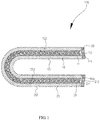
- a first embodiment of the present disclosure provides a flexible screen protection structure 100.
- the flexible screen protection structure 100 includes a first flexible plate 10, a second flexible plate 20, a side plate 30, a number of first trapezoidal bosses 11, and a number of second trapezoidal bosses 21.
- the second flexible plate 20 is arranged opposite to the first flexible plate 10, and a gap 10a is formed between the first flexible plate 10 and the second flexible plate 20.
- the side plate 30 surrounds peripheral sides of the first flexible plate 10 and peripheral sides of the second flexible plate 20, and closes the gap 10a.
- the first trapezoidal bosses 11 are densely distributed on the first flexible plate 10 and located in the gap 10a. Each first trapezoidal boss 11 includes a large end 111 attached to the first flexible plate 10 and a small end 112 facing the second flexible plate 20.
- the second trapezoidal bosses 21 are densely distributed on the second flexible plate 20 and located in the gap 10a.
- Each second trapezoidal boss 21 includes a large end 211 attached to the second flexible plate 20 and a small end 212 facing the first flexible plate 10.
- the flexible screen protection structure 100 can be bent to a certain degree.
- the small ends 112 of the first trapezoidal bosses 11 or the small ends 212 of the second trapezoidal bosses 21 abut against each other, a maximum bending limit of the flexible screen protection structure 100 is reached, the flexible screen protection structure 100 cannot be bent any longer, thus deflection of the flexible screen protection structure 100 can be prevented, and the deflection resistance can be further improved.
- the first flexible plate 10 is a rectangular plate.
- the first flexible plate 10 can be bent freely.
- the first flexible plate 10 includes a first outer surface 101 and a first inner surface 102 opposite to the first outer surface 101.
- the first inner surface 102 faces the second flexible plate 20, and the first trapezoidal bosses 11 are densely distributed on the first inner surface 102.
- the first inner surface 102 can be bonded with the first trapezoidal bosses 11, or can be integrated with the first trapezoidal bosses 11, or still can be engaged with the first trapezoidal bosses 11.
- the first flexible plate 10 still can be in a circular shape or other polygonal shapes.
- the second flexible plate 20 is a rectangular plate.
- the second flexible plate 20 has a size equivalent to that of the first flexible plate 10, and has a second outer surface 201 and a second inner surface 202 opposite to the second outer surface 201.
- the second flexible plate 20 can have the same material and the same structure as the first flexible plate 10.
- the second flexible plate 20 can be bent freely, and the second trapezoidal bosses 21 are arranged on the second inner surface 202 in a manner similar to that in which the first trapezoidal bosses 11 are provided, which will not be repeated herein.
- the first trapezoidal bosses 11 are trapezoidal frustums of square pyramids (that is, sections in a direction perpendicular to the height of the bosses are square, as shown in FIG. 1 and FIG. 2 ).
- a clearance is formed between the small ends 112 of two adjacent first trapezoidal bosses 11, and the large ends 111 of two adjacent first trapezoidal bosses 11 abut against each other and both are fixed to the first inner surface 102.
- the first trapezoidal bosses 11 are arranged into arrays on the first flexible plate 10. Specifically, the first trapezoidal bosses 11 are arranged into arrays in a length direction of the first flexible plate 10, and are arranged into arrays in a width direction of the first flexible plate 10. The large ends 111 of two adjacent first trapezoidal bosses 11 are closely connected, and the small ends 112 of two adjacent first trapezoidal bosses 11 are arranged to leave a gap.
- the small ends 111 of two adjacent columns of the first trapezoidal bosses 11 in the length or width direction get close to each other, so that the bending of the first flexible plate 10 in the length direction or the width direction has a certain bending radius.
- the small ends 111 of two adjacent columns of first trapezoidal bosses 11 in the length or width direction abut and stay together, the first flexible plate 10 cannot be bent any longer, so that the bending of the first flexible plate 10 in the length direction or in the width direction has a certain bending limit, thus deflection of the first flexible plate 10 can be prevented, and the first flexible plate 10 can be protected.
- the first flexible pate 10 can be bent in the length direction or in the width direction, and the bending in the length direction or in the width direction has a maximum bending limit
- the first flexible plate 10 also can be bent in other directions, and the bending in each of the other directions has a maximum bending limit.
- the first flexible plate 10 can be bent along a diagonal direction, that is, at the place of the diagonal line, the small ends 112 of two adjacent lines of first trapezoidal bosses 11 can get close, so that the first flexible plate 10 can be bent at the place of the diagonal line.
- the first flexible plate 10 cannot be bent any longer, thus the maximum bending limit of the first flexible plate 10 is reached.
- the first flexible plate 10 can be bent in any direction, and the bending in each direction has a maximum bending limit, thus deflection of the first flexible plate 10 can be prevented, and the function of protecting the first flexible plate 10 can be realized.
- the structure of the second trapezoidal bosses 21, the arrangement manner of the second trapezoidal bosses 21, and functions realized by the second trapezoidal bosses 21 are similar to the above description about the first trapezoidal bosses 11, which will not be repeated herein.
- first trapezoidal bosses 11 and the second trapezoidal bosses 12 are sealed in the gap 10a, thus the first trapezoidal bosses 11 and the second trapezoidal bosses 12 can be protected.
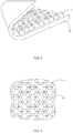
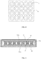
- the first trapezoidal bosses 11 also can be hexagonal trapezoidal frustums of pyramids (that is, cross sections of the first trapezoidal bosses are regular hexagon , as shown in FIG. 3 ) or trapezoidal truncated cones (that is, cross sections of the trapezoidal bosses are circular, as shown in FIG. 4 ) and so on.
- structures such as multi-angular trapezoidal frustums of pyramids (for example, hexagonal trapezoidal frustums of pyramids) and trapezoidal truncated cones are more advantageous for bending the flexible screen protection structure 100 in multiple directions.
- the first flexible plate 10 is made from an elastic material.
- the elastic material is polyethylene fiber.
- the first flexible plate 10 is always in a bent state. After the external force is removed, molecular chains of the first flexible plate 10 are turned into an extended state from the bent state through molecules stress of the first flexible plate 10, so that the first flexible plate 10 is enabled to restore to an expanded state.
- the first flexible plate 10 also can be made from an elastic material such as highly elastic rubber or highly elastic carbon fiber.
- the second flexible plate 20 is also made from an elastic material.
- the second flexible plate 20 can be made from the above mentioned polyethylene fiber, highly elastic rubber, or highly elastic carbon fiber.
- the principle applied to the second flexible plate 20 is the same as that applied to the first flexible plate 10, which will not be repeated herein.
- the side plate 30 is made from an elastic material.
- the side plate 30 can be made from polyethylene fiber.
- the side plate 30 is bonded to the peripheral sides of the first flexible plate 10 and the second flexible plate 20, when the first flexible plate 10 is bent with respect to the second flexible plate 20 under the effect of an external force, a dislocation will be generated between the first flexible plate 10 and the second flexible plate 20, so the side plate 30 also will be deformed. After the external force is removed, molecular chains of the side plate 30 are turned into a natural extended state from the deformed state through the molecules stress of the side plate 30, so that the side plate 30 is enabled to restore to its natural state, and the dislocation between the first flexible plate 10 and the second flexible plate 20 is eliminated.
- the side plate 30 is made from highly elastic rubber or a highly elastic carbon fiber.
- the first flexible plate 10 and the second flexible 20 are magnetically attracted to each other.
- the first flexible plate 10 is coated with a first magnetic layer 101a
- the second flexible plate 20 is coated with a second magnetic layer 201a.
- an atmospheric pressure intensity inside the gap 10a is smaller than an atmospheric pressure intensity outside the flexible screen protection structure 100.
- air inside the gap 10a can be extracted, so that the gap 10a is evacuated, and so that the atmospheric pressure intensity in the gap 10a is smaller than the atmospheric pressure intensity outside the flexible screen protection structure 100, thus both the first outer surface 101 of the first flexible plate 10 and the second outer surface 201 of the second flexible plate 20 are subjected to a pressure difference of the external pressure intensity, so that the first flexible plate 10 and the second flexible plate 20 cannot be easily separated, the first flexible plate 10 and the second flexible plate 20 can be prevented from producing the raised deformation, and the performances of the flexible screen protection structure 100 can be further improved.
- the preferable embodiment in which the first flexible plate 10 and the second flexible plate 20 are magnetically attracted to each other also can be combined with the present embodiment.
- the present disclosure provides the flexible screen protection structure 100 of a second embodiment.
- the present embodiment is substantially the same as the first embodiment, and the difference is that the gap 10a is filled with electrorheological fluid, and a voltage can be applied between the first flexible plate 10 and the second flexible plate 20.
- the first flexible plate 10 is a metal plate
- the second flexible plate 20 is a metal plate.
- the first flexible plate 10 and the second flexible plate 20 can be respectively electrically coupled to an anode and a cathode of a power source (not shown in the figures), so that a voltage is generated between the first flexible plate 10 and the second flexible plate 20.
- the flexible screen protection structure 100 cannot be deformed.
- both the first flexible plate 10 and the second flexible plate 20 can be metal plates having high elasticity.
- the flexible screen protection structure 100 can be bent freely, and the flexible screen protection structure 100 can restore to the expanded state after the external force is removed.
- the power source is then switched on, the flexible screen protection structure 100 is shaped into the predetermined state.
- the first trapezoidal bosses 11 are respectively arranged opposite to the second trapezoidal bosses 21 one to one.
- the support structure of the flexible screen protection structure 100 is strengthened, and the pressure resistance of the flexible screen protection structure 100 is enhanced.
- the first trapezoidal bosses 11 and the second trapezoidal bosses 21 are coupled in series through a cable. Specifically, the first trapezoidal bosses 11 are firstly coupled in series through a cable 1a, and then the second trapezoidal bosses 21 are successively coupled in series through the cable 1a. Thus, the first trapezoidal bosses 11 cannot be easily disengaged from the second trapezoidal bosses 21, neither the first flexible plate 10 nor the second flexible plate 20 will produce the raised deformation, thus enhancing performances of the flexible screen protection structure 100.
- each corresponding column of the first trapezoidal bosses 11 and the second trapezoidal bosses 21 are firstly coupled in series, or each corresponding row of the first trapezoidal bosses 11 and the second trapezoidal bosses 21 are coupled in series.
- the present disclosure further provides a flexible display screen 200.
- the flexible display screen 200 includes the flexible screen protection structure 100 and an organic light-emitting display layer 40.
- the organic light-emitting display layer 40 is stacked on the flexible screen protection structure 100.
- the organic light-emitting display layer 40 can be stacked on the first outer surface 101 of the first flexible plate 10, and also can be stacked on the second outer surface 201 of the second flexible plate 20.
- the organic light-emitting display layer 40 also can be stacked between the first trapezoidal bosses 11 and the second trapezoidal bosses 21.
- the present disclosure further provides a method for manufacturing a flexible screen protection structure.
- the flexible screen protection structure 100 can be manufactured by the method for manufacturing a flexible screen protection structure.
- the method for manufacturing a flexible screen protection structure may include the following steps.
- the predetermined profile is in a rectangular shape, that is, the first flexible plate and the second flexible plate are rectangular plates.
- S02 holes are punched in multiple predetermined positions of the first flexible plate and the second flexible plate.
- the punched holes in the multiple predetermined positions are arranged into array on the first flexible plate and the second flexible plate; S03: The first flexible plate provided with the punched holes is placed in an injection mold of first trapezoidal bosses for injection molding.
- the first trapezoidal bosses are shaped in the punched holes.
- the second trapezoidal bosses are shaped in the punched holes.
- peripheral sides of the first flexible plate and peripheral sides of the second flexible plate are simultaneously encapsulated with a side plate.
- the step S03 and the step S04 also can be combined into one step for carrying out.
- the flexible screen protection structure of the present disclosure by providing the first trapezoidal bosses and the second trapezoidal bosses respectively on the first flexible plate and the second flexible plate, and using the clearances existing between the small ends of the first trapezoidal bosses and the clearances existing between the small ends of the second trapezoidal bosses, the flexible screen protection structure can be bent to a certain degree.
- the small ends of the first trapezoidal bosses or the small ends of the second trapezoidal bosses abut against each other, so that the flexible screen protection structure cannot be bent any longer, thus deflection of the flexible screen protection structure can be prevented, and the deflection resistance can be further improved.
Abstract
Description
- The present disclosure relates to the field of flexible screens, and particularly to a flexible screen protection structure and a method for manufacturing the same, and a flexible display screen using the same.
- With the development of flexible display technology, not only small-range bending of a fixed radian of a flexible display screen can be realized, but also any bending of a large curvature and even winding can be realized. However, at present, the bending curvature of the flexible display screen still has a certain maximum limit, for example, right-angle flexing cannot be realized. When a bending degree of the flexible display screen exceeds an allowable maximum limit and the flexible display screen is even flexed, the flexible display screen will be bent and cracked, i.e. deflection phenomenon will occur, which causes that the flexible display screen cannot be normally used. Therefore, it is necessary to provide a protection structure which can prevent the flexible display screen from being damaged during the bending process.
- The object of the present disclosure is to provide a flexible screen protection structure that improves deflection resistance, a method for manufacturing the same, and a flexible display screen using the same.
- In order to solve the above problems, the present disclosure provides a flexible screen protection structure. The flexible screen protection structure includes a first flexible plate, a second flexible plate, a side plate, a number of first trapezoidal bosses, and a number of second trapezoidal bosses.
- The second flexible plate is provided opposite to the first flexible plate, and a gap is formed between the first flexible plate and the second flexible plate.
- The side plate surrounds peripheral sides of the first flexible plate and peripheral sides of the second flexible plate, and closes the gap.
- The first trapezoidal bosses are densely distributed on the first flexible plate and located in the gap, and each first trapezoidal boss includes a large end attached to the first flexible plate and a small end facing the second flexible plate.
- The second trapezoidal bosses are densely distributed on the second flexible plate and located in the gap, and each second trapezoidal boss includes a large end attached to the second flexible plate and a small end facing the first flexible plate.
- The first flexible plate is made from an elastic material, and the first flexible plate is able to restore to an expanded state after being bent.
- The second flexible plate is made from an elastic material, and the second flexible plate is able to restore to an expanded state after being bent.
- The side plate is made from an elastic material, and the side plate is able to restore to an expanded state after being bent.
- The gap is filled with electrorheological fluid, and a voltage is allowed to be applied between the first flexible plate and the second flexible plate.
- The first flexible plate and the second flexible plate are magnetically attracted to each other.
- The first trapezoidal bosses and the second trapezoidal bosses are coupled in series through a cable.
- The first trapezoidal bosses are arranged into array on the first flexible plate, and the second trapezoidal bosses are arranged into array on the second flexible plate.
- The first trapezoidal bosses are respectively provided opposite to the second trapezoidal bosses one to one.
- The first trapezoidal bosses and the second trapezoidal bosses are trapezoidal truncated cones.
- An atmospheric pressure intensity in the gap is smaller than an atmospheric pressure intensity outside the flexible screen protection structure.
- The present disclosure further provides a flexible display screen. The flexible display screen includes the flexible screen protection structure of any one of the above, and the flexible display screen further includes an organic light-emitting display layer. The organic light-emitting display layer is stacked on the flexible screen protection structure.
- The organic light-emitting display layer is stacked on a surface of the first flexible plate facing away from the second flexible plate or on a surface of the second flexible plate facing away from the first flexible plate.
- The present disclosure further provides a method for manufacturing a flexible screen protection structure, and the flexible screen protection structure of any one of the above is manufactured by the method for manufacturing a flexible screen protection structure. The method for manufacturing a flexible screen protection structure includes steps of: providing a first flexible plate having a predetermined profile and a second flexible plate having a predetermined profile; punching holes in a number of predetermined positions of the first flexible plate and the second flexible plate; placing the first flexible plate provided with the punched holes in an injection mold of first trapezoidal bosses for injection molding; placing the second flexible plate provided with the punched holes in an injection mold of second trapezoidal bosses for injection molding; arranging the first trapezoidal bosses to abut against the second trapezoidal bosses; encapsulating peripheral sides of the first flexible plate and the second flexible plate simultaneously with a side plate.
- For the flexible screen protection structure of the present disclosure, by providing the first trapezoidal bosses and the second trapezoidal bosses respectively on the first flexible plate and the second flexible plate, and using the clearances existing between the small ends of the first trapezoidal bosses and the clearances between the small ends of the second trapezoidal bosses, the flexible screen protection structure can be bent to a certain degree. When the flexible screen protection structure is to be deflected, the small ends of the first trapezoidal bosses or the small ends of the second trapezoidal bosses abut against each other, so that the flexible screen protection structure cannot be bent any longer, thus deflection of the flexible screen protection structure can be prevented, and the deflection resistance can be further improved.
- In order to more clearly illustrate the technical solutions of the present disclosure, figures which are needed in the embodiments will be introduced briefly below. Apparently, the figures in the description below are merely for some embodiments of the present disclosure, and a person ordinarily skilled in the art still can obtain other figures according to these figures, without paying creative effort.
-
FIG. 1 is a sectional schematic view of a flexible screen protection structure in accordance with a first embodiment of the present disclosure. -
FIG. 2 is a schematic view showing a first flexible plate of the flexible screen protection structure ofFIG. 1 bent along a diagonal line. -
FIG. 3 is a schematic view of first trapezoidal bosses of the flexible screen protection structure ofFIG. 1 , the first trapezoidal bosses being hexagonal trapezoidal pattern. -
FIG. 4 is a schematic view of the first trapezoidal bosses of the flexible screen protection structure ofFIG. 1 , the first trapezoidal bosses being trapezoidal truncated cones. -
FIG. 5 is a schematic view showing the first flexible plate and a second flexible plate of the flexible screen protection structure ofFIG. 1 magnetically attracted to each other. -
FIG. 6 is a sectional schematic view of a flexible screen protection structure in accordance with a second embodiment of the present disclosure. -
FIG. 7 is a schematic view showing first trapezoidal bosses and second trapezoidal bosses of the flexible screen protection structure ofFIG. 6 coupled in series through a cable. -
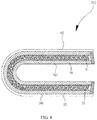
FIG. 8 is a sectional schematic view of a flexible display screen of the present disclosure. -
FIG. 9 is a flow chart of a method for manufacturing a flexible screen protection structure of the present disclosure. - Below technical solutions of embodiments of the present disclosure will be described clearly and completely in conjunction with figures of the embodiments of the present disclosure.
- Referring to
FIG. 1 , a first embodiment of the present disclosure provides a flexiblescreen protection structure 100. The flexiblescreen protection structure 100 includes a firstflexible plate 10, a secondflexible plate 20, aside plate 30, a number of firsttrapezoidal bosses 11, and a number of secondtrapezoidal bosses 21. - The second
flexible plate 20 is arranged opposite to the firstflexible plate 10, and a gap 10a is formed between the firstflexible plate 10 and the secondflexible plate 20. - The
side plate 30 surrounds peripheral sides of the firstflexible plate 10 and peripheral sides of the secondflexible plate 20, and closes the gap 10a. - The first
trapezoidal bosses 11 are densely distributed on the firstflexible plate 10 and located in the gap 10a. Each firsttrapezoidal boss 11 includes alarge end 111 attached to the firstflexible plate 10 and asmall end 112 facing the secondflexible plate 20. - The second
trapezoidal bosses 21 are densely distributed on the secondflexible plate 20 and located in the gap 10a. Each secondtrapezoidal boss 21 includes alarge end 211 attached to the secondflexible plate 20 and asmall end 212 facing the firstflexible plate 10. - By providing the first
trapezoidal bosses 11 and the secondtrapezoidal bosses 21 on the firstflexible plate 10 and the secondtrapezoidal bosses 21 respectively, and making use of clearances existing between thesmall ends 112 of the firsttrapezoidal bosses 11 and clearances existing between thesmall ends 212 of the secondtrapezoidal bosses 21, the flexiblescreen protection structure 100 can be bent to a certain degree. When thesmall ends 112 of the firsttrapezoidal bosses 11 or thesmall ends 212 of the secondtrapezoidal bosses 21 abut against each other, a maximum bending limit of the flexiblescreen protection structure 100 is reached, the flexiblescreen protection structure 100 cannot be bent any longer, thus deflection of the flexiblescreen protection structure 100 can be prevented, and the deflection resistance can be further improved. - As a preferable embodiment, the first
flexible plate 10 is a rectangular plate. The firstflexible plate 10 can be bent freely. The firstflexible plate 10 includes a firstouter surface 101 and a firstinner surface 102 opposite to the firstouter surface 101. The firstinner surface 102 faces the secondflexible plate 20, and the firsttrapezoidal bosses 11 are densely distributed on the firstinner surface 102. The firstinner surface 102 can be bonded with the firsttrapezoidal bosses 11, or can be integrated with the firsttrapezoidal bosses 11, or still can be engaged with the firsttrapezoidal bosses 11. In other embodiments, the firstflexible plate 10 still can be in a circular shape or other polygonal shapes. - As a preferable embodiment, the second
flexible plate 20 is a rectangular plate. The secondflexible plate 20 has a size equivalent to that of the firstflexible plate 10, and has a secondouter surface 201 and a secondinner surface 202 opposite to the secondouter surface 201. The secondflexible plate 20 can have the same material and the same structure as the firstflexible plate 10. Likewise, the secondflexible plate 20 can be bent freely, and the secondtrapezoidal bosses 21 are arranged on the secondinner surface 202 in a manner similar to that in which the firsttrapezoidal bosses 11 are provided, which will not be repeated herein. - As a preferable embodiment, the first
trapezoidal bosses 11 are trapezoidal frustums of square pyramids (that is, sections in a direction perpendicular to the height of the bosses are square, as shown inFIG. 1 andFIG. 2 ). A clearance is formed between thesmall ends 112 of two adjacent firsttrapezoidal bosses 11, and the large ends 111 of two adjacent firsttrapezoidal bosses 11 abut against each other and both are fixed to the firstinner surface 102. When the firstflexible plate 10 is bent towards the side of the firsttrapezoidal bosses 11, two adjacent firsttrapezoidal bosses 11 at the place where the firstinner surface 102 is bent get close to each other, and the clearance between thesmall ends 112 of two adjacent firsttrapezoidal bosses 11 gradually decreases until thesmall ends 112 of the two adjacent firsttrapezoidal bosses 11 abut against each other. As shown on the left inFIG. 1 , the bending of the firstflexible plate 10 stops, then the firstflexible plate 10 has a certain bending radius, and the firstflexible plate 10 has no deflection, thus the firstflexible plate 10 can be protected, and the use efficiency of the flexiblescreen protection structure 100 can be improved. - As a preferable embodiment, the first
trapezoidal bosses 11 are arranged into arrays on the firstflexible plate 10. Specifically, the firsttrapezoidal bosses 11 are arranged into arrays in a length direction of the firstflexible plate 10, and are arranged into arrays in a width direction of the firstflexible plate 10. The large ends 111 of two adjacent firsttrapezoidal bosses 11 are closely connected, and thesmall ends 112 of two adjacent firsttrapezoidal bosses 11 are arranged to leave a gap. When the firstflexible plate 10 is bent in the length direction or in the width direction, at the place where the firstflexible plate 10 is bent, thesmall ends 111 of two adjacent columns of the firsttrapezoidal bosses 11 in the length or width direction get close to each other, so that the bending of the firstflexible plate 10 in the length direction or the width direction has a certain bending radius. When thesmall ends 111 of two adjacent columns of firsttrapezoidal bosses 11 in the length or width direction abut and stay together, the firstflexible plate 10 cannot be bent any longer, so that the bending of the firstflexible plate 10 in the length direction or in the width direction has a certain bending limit, thus deflection of the firstflexible plate 10 can be prevented, and the firstflexible plate 10 can be protected. - Certainly, besides that the first
flexible pate 10 can be bent in the length direction or in the width direction, and the bending in the length direction or in the width direction has a maximum bending limit, the firstflexible plate 10 also can be bent in other directions, and the bending in each of the other directions has a maximum bending limit. For example, as shown inFIG. 2 , the firstflexible plate 10 can be bent along a diagonal direction, that is, at the place of the diagonal line, thesmall ends 112 of two adjacent lines of firsttrapezoidal bosses 11 can get close, so that the firstflexible plate 10 can be bent at the place of the diagonal line. At the place of the diagonal line, when thesmall ends 111 of two adjacent lines of firsttrapezoidal bosses 11 abut against each other, the firstflexible plate 10 cannot be bent any longer, thus the maximum bending limit of the firstflexible plate 10 is reached. According to the same principle, the firstflexible plate 10 can be bent in any direction, and the bending in each direction has a maximum bending limit, thus deflection of the firstflexible plate 10 can be prevented, and the function of protecting the firstflexible plate 10 can be realized. - The structure of the second
trapezoidal bosses 21, the arrangement manner of the secondtrapezoidal bosses 21, and functions realized by the secondtrapezoidal bosses 21 are similar to the above description about the firsttrapezoidal bosses 11, which will not be repeated herein. - As a preferable embodiment, the first
trapezoidal bosses 11 and the second trapezoidal bosses 12 are sealed in the gap 10a, thus the firsttrapezoidal bosses 11 and the second trapezoidal bosses 12 can be protected. - In other embodiments, the first
trapezoidal bosses 11 also can be hexagonal trapezoidal frustums of pyramids (that is, cross sections of the first trapezoidal bosses are regular hexagon , as shown inFIG. 3 ) or trapezoidal truncated cones (that is, cross sections of the trapezoidal bosses are circular, as shown inFIG. 4 ) and so on. Compared with the trapezoidal frustums of square pyramids, structures such as multi-angular trapezoidal frustums of pyramids (for example, hexagonal trapezoidal frustums of pyramids) and trapezoidal truncated cones are more advantageous for bending the flexiblescreen protection structure 100 in multiple directions. - Furthermore, the first
flexible plate 10 is made from an elastic material. As a preferable embodiment, the elastic material is polyethylene fiber. Under the effect of an external force, no matter the flexiblescreen protection structure 100 is bent toward the side of the firstflexible plate 10 or toward the side of the secondflexible plate 20, the firstflexible plate 10 is always in a bent state. After the external force is removed, molecular chains of the firstflexible plate 10 are turned into an extended state from the bent state through molecules stress of the firstflexible plate 10, so that the firstflexible plate 10 is enabled to restore to an expanded state. In other embodiments, the firstflexible plate 10 also can be made from an elastic material such as highly elastic rubber or highly elastic carbon fiber. - Furthermore, the second
flexible plate 20 is also made from an elastic material. As a preferable embodiment, the secondflexible plate 20 can be made from the above mentioned polyethylene fiber, highly elastic rubber, or highly elastic carbon fiber. The principle applied to the secondflexible plate 20 is the same as that applied to the firstflexible plate 10, which will not be repeated herein. - Furthermore, the
side plate 30 is made from an elastic material. As a preferable embodiment, theside plate 30 can be made from polyethylene fiber. As theside plate 30 is bonded to the peripheral sides of the firstflexible plate 10 and the secondflexible plate 20, when the firstflexible plate 10 is bent with respect to the secondflexible plate 20 under the effect of an external force, a dislocation will be generated between the firstflexible plate 10 and the secondflexible plate 20, so theside plate 30 also will be deformed. After the external force is removed, molecular chains of theside plate 30 are turned into a natural extended state from the deformed state through the molecules stress of theside plate 30, so that theside plate 30 is enabled to restore to its natural state, and the dislocation between the firstflexible plate 10 and the secondflexible plate 20 is eliminated. In other embodiments, theside plate 30 is made from highly elastic rubber or a highly elastic carbon fiber. - Furthermore, referring to
FIG. 5 , the firstflexible plate 10 and the second flexible 20 are magnetically attracted to each other. As a preferable embodiment, the firstflexible plate 10 is coated with a firstmagnetic layer 101a, and the secondflexible plate 20 is coated with a secondmagnetic layer 201a. By the property that the firstflexible plate 10 and the second flexible 20 can attract each other, the firsttrapezoidal bosses 11 are caused to abut against the secondtrapezoidal bosses 21 under the effect of a magnetic force, so that the firsttrapezoidal bosses 11 cannot be easily disengaged from the secondtrapezoidal bosses 21, neither the firstflexible plate 10 nor the secondflexible plate 20 can easily produce raised deformation, thus performances of the flexiblescreen protection structure 100 can be further enhanced. - Furthermore, an atmospheric pressure intensity inside the gap 10a is smaller than an atmospheric pressure intensity outside the flexible
screen protection structure 100. In another embodiment, air inside the gap 10a can be extracted, so that the gap 10a is evacuated, and so that the atmospheric pressure intensity in the gap 10a is smaller than the atmospheric pressure intensity outside the flexiblescreen protection structure 100, thus both the firstouter surface 101 of the firstflexible plate 10 and the secondouter surface 201 of the secondflexible plate 20 are subjected to a pressure difference of the external pressure intensity, so that the firstflexible plate 10 and the secondflexible plate 20 cannot be easily separated, the firstflexible plate 10 and the secondflexible plate 20 can be prevented from producing the raised deformation, and the performances of the flexiblescreen protection structure 100 can be further improved. In other embodiments, the preferable embodiment in which the firstflexible plate 10 and the secondflexible plate 20 are magnetically attracted to each other also can be combined with the present embodiment. - Furthermore, as shown in
FIG. 6 , the present disclosure provides the flexiblescreen protection structure 100 of a second embodiment. The present embodiment is substantially the same as the first embodiment, and the difference is that the gap 10a is filled with electrorheological fluid, and a voltage can be applied between the firstflexible plate 10 and the secondflexible plate 20. - As a preferable embodiment, the first
flexible plate 10 is a metal plate, and the secondflexible plate 20 is a metal plate. The firstflexible plate 10 and the secondflexible plate 20 can be respectively electrically coupled to an anode and a cathode of a power source (not shown in the figures), so that a voltage is generated between the firstflexible plate 10 and the secondflexible plate 20. For example, when the firstflexible plate 10 is coupled to the anode of the power source, and the secondflexible plate 20 is coupled to the cathode of the power source, and the power source coupled to the firstflexible plate 10 and the secondflexible plate 20 is powered on, a voltage is generated between the firstflexible plate 10 and the secondflexible plate 20, so that the electrorheological fluid inside the gap 10a is turned from a liquid state into a solid state, thus a support structure of a solid plate is presented between the firstflexible plate 10 and the secondflexible plate 20, thus the flexiblescreen protection structure 100 cannot be deformed. That is, after the flexiblescreen protection structure 100 is bent to a predetermined shape under the effect of an external force, and a voltage is applied to the flexiblescreen protection structure 100, and when the external force is removed, the flexiblescreen protection structure 100 still cannot restore to the expanded state, so that the flexiblescreen protection structure 100 is shaped into a predetermined state. In other embodiments, both the firstflexible plate 10 and the secondflexible plate 20 can be metal plates having high elasticity. When the power source is not switched on, the flexiblescreen protection structure 100 can be bent freely, and the flexiblescreen protection structure 100 can restore to the expanded state after the external force is removed. When the flexiblescreen protection structure 100 is bent into the predetermined state under the effect of an external force, the power source is then switched on, the flexiblescreen protection structure 100 is shaped into the predetermined state. - Furthermore, under the expanded state without an external force, the first
trapezoidal bosses 11 are respectively arranged opposite to the secondtrapezoidal bosses 21 one to one. With such structure, the support structure of the flexiblescreen protection structure 100 is strengthened, and the pressure resistance of the flexiblescreen protection structure 100 is enhanced. - As a preferable embodiment, as shown in
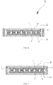
FIG. 7 , the firsttrapezoidal bosses 11 and the secondtrapezoidal bosses 21 are coupled in series through a cable. Specifically, the firsttrapezoidal bosses 11 are firstly coupled in series through acable 1a, and then the secondtrapezoidal bosses 21 are successively coupled in series through thecable 1a. Thus, the firsttrapezoidal bosses 11 cannot be easily disengaged from the secondtrapezoidal bosses 21, neither the firstflexible plate 10 nor the secondflexible plate 20 will produce the raised deformation, thus enhancing performances of the flexiblescreen protection structure 100. In other embodiments, each corresponding column of the firsttrapezoidal bosses 11 and the secondtrapezoidal bosses 21 are firstly coupled in series, or each corresponding row of the firsttrapezoidal bosses 11 and the secondtrapezoidal bosses 21 are coupled in series. - Referring to
FIG. 8 , the present disclosure further provides aflexible display screen 200. Theflexible display screen 200 includes the flexiblescreen protection structure 100 and an organic light-emittingdisplay layer 40. The organic light-emittingdisplay layer 40 is stacked on the flexiblescreen protection structure 100. Specifically, the organic light-emittingdisplay layer 40 can be stacked on the firstouter surface 101 of the firstflexible plate 10, and also can be stacked on the secondouter surface 201 of the secondflexible plate 20. In other embodiments, the organic light-emittingdisplay layer 40 also can be stacked between the firsttrapezoidal bosses 11 and the secondtrapezoidal bosses 21. - Referring to
FIG. 9 , the present disclosure further provides a method for manufacturing a flexible screen protection structure. The flexiblescreen protection structure 100 can be manufactured by the method for manufacturing a flexible screen protection structure. The method for manufacturing a flexible screen protection structure may include the following steps. - S01: a first flexible plate having a predetermined profile and a second flexible plate having a predetermined profile are provided.
- In the embodiment, the predetermined profile is in a rectangular shape, that is, the first flexible plate and the second flexible plate are rectangular plates.
- S02: holes are punched in multiple predetermined positions of the first flexible plate and the second flexible plate.
- The punched holes in the multiple predetermined positions are arranged into array on the first flexible plate and the second flexible plate;
S03: The first flexible plate provided with the punched holes is placed in an injection mold of first trapezoidal bosses for injection molding. - In the present embodiment, the first trapezoidal bosses are shaped in the punched holes.
- S04: the second flexible plate provided with the punched holes is placed in an injection mold of second trapezoidal bosses for injection molding.
- In the present embodiment, the second trapezoidal bosses are shaped in the punched holes.
- S05: the first trapezoidal bosses are arranged to abut against the second trapezoidal bosses.
- S06: peripheral sides of the first flexible plate and peripheral sides of the second flexible plate are simultaneously encapsulated with a side plate.
- In other embodiments, when the first
flexible plate 10 and the secondflexible plate 20 have the same structure, and the firsttrapezoidal bosses 11 and the secondtrapezoidal bosses 21 have the same structure, the step S03 and the step S04 also can be combined into one step for carrying out. - For the flexible screen protection structure of the present disclosure, by providing the first trapezoidal bosses and the second trapezoidal bosses respectively on the first flexible plate and the second flexible plate, and using the clearances existing between the small ends of the first trapezoidal bosses and the clearances existing between the small ends of the second trapezoidal bosses, the flexible screen protection structure can be bent to a certain degree. When the flexible screen protection structure is to be deflected, the small ends of the first trapezoidal bosses or the small ends of the second trapezoidal bosses abut against each other, so that the flexible screen protection structure cannot be bent any longer, thus deflection of the flexible screen protection structure can be prevented, and the deflection resistance can be further improved.
- The above-mentioned are merely for preferable embodiments of the present disclosure. It shall be indicated that for a person ordinarily skilled in the art, improvements and modifications still can be made within the principle of the present disclosure, and these improvements and modifications also should be considered as the protection scope of the present disclosure.
Claims (14)
- A flexible screen protection structure, comprising:a first flexible plate;a second flexible plate opposite to the first flexible plate, wherein a gap is formed between the first flexible plate and the second flexible plate;a side plate surrounding peripheral sides of the first flexible plate and peripheral sides of the second flexible plate and closing the gap;a plurality of first trapezoidal bosses densely distributed on the first flexible plate and located in the gap, wherein each of the plurality of the first trapezoidal bosses comprises a large end attached to the first flexible plate and a small end facing the second flexible plate; anda plurality of second trapezoidal bosses densely distributed on the second flexible plate and located in the gap, wherein each of the plurality of the second trapezoidal bosses comprises a large end attached to the second flexible plate and a small end facing the first flexible plate.
- The flexible screen protection structure of claim 1, characterized in that the first flexible plate is made from an elastic material, and the first flexible plate is able to restore to an expanded state after being bent.
- The flexible screen protection structure of claim 1, characterized in that the second flexible plate is made from an elastic material, and the second flexible plate is able to restore to an expanded state after being bent.
- The flexible screen protection structure of claim 1, characterized in that the side plate is made from an elastic material, and the side plate is able to restore to an expanded state after being bent.
- The flexible screen protection structure of claim 1, characterized in that the gap is filled with electrorheological fluid, and a voltage is allowed to be applied between the first flexible plate and the second flexible plate.
- The flexible screen protection structure of claim 1, characterized in that the first flexible plate and the second flexible plate are magnetically attracted to each other.
- The flexible screen protection structure of claim 1, characterized in that the plurality of the first trapezoidal bosses and the plurality of the second trapezoidal bosses are coupled in series through a cable.
- The flexible screen protection structure of claim 1, characterized in that the plurality of the first trapezoidal bosses are arranged into array on the first flexible plate, and the plurality of the second trapezoidal bosses are in arranged into array on the second flexible plate.
- The flexible screen protection structure of claim 8, characterized in that the plurality of the first trapezoidal bosses are respectively provided opposite to the plurality of the second trapezoidal bosses one to one.
- The flexible screen protection structure of claim 8 or claim 9, characterized in that the plurality of the first trapezoidal bosses and the plurality of the second trapezoidal bosses are trapezoidal truncated cones.
- The flexible screen protection structure of claim 1, characterized in that an atmospheric pressure intensity in the gap is smaller than an atmospheric pressure intensity outside the flexible screen protection structure.
- A flexible display screen, characterized in that the flexible display screen comprises the flexible screen protection structure of any of claims 1-11, the flexible display screen further comprises an organic light-emitting display layer, and the organic light-emitting display layer is stacked on the flexible screen protection structure.
- The flexible display screen of claim 12, characterized in that the organic light-emitting display layer is stacked on a surface of the first flexible plate facing away from the second flexible plate or on a surface of the second flexible plate facing away from the first flexible plate.
- A method for manufacturing a flexible screen protection structure, characterized in that the flexible screen protection structure of any of claims 1-11 is manufactured by the method for manufacturing a flexible screen protection structure, the method for manufacturing a flexible screen protection structure comprises steps of:providing a first flexible plate having a predetermined profile and a second flexible plate having a predetermined profile;punching holes in a plurality of predetermined positions of the first flexible plate and the second flexible plate;placing the first flexible plate provided with the punched holes in an injection mold of first trapezoidal bosses for injection molding;placing the second flexible plate provided with the punched holes in an injection mold of second trapezoidal bosses for injection molding;arranging the first trapezoidal bosses to abut against the second trapezoidal bosses; andencapsulating peripheral sides of the first flexible plate and peripheral sides of the second flexible plate simultaneously with a side plate.
Applications Claiming Priority (1)
| Application Number | Priority Date | Filing Date | Title |
|---|---|---|---|
| PCT/CN2014/093229 WO2016090527A1 (en) | 2014-12-08 | 2014-12-08 | Flexible screen protection structure and manufacturing method therefor, and flexible display screen applying flexible screen protection structure |
Publications (3)
| Publication Number | Publication Date |
|---|---|
| EP3232425A1 true EP3232425A1 (en) | 2017-10-18 |
| EP3232425A4 EP3232425A4 (en) | 2018-08-01 |
| EP3232425B1 EP3232425B1 (en) | 2021-01-27 |
Family
ID=55725042
Family Applications (1)
| Application Number | Title | Priority Date | Filing Date |
|---|---|---|---|
| EP14907752.1A Active EP3232425B1 (en) | 2014-12-08 | 2014-12-08 | Flexible screen protection structure and manufacturing method therefor, and flexible display screen applying flexible screen protection structure |
Country Status (6)
| Country | Link |
|---|---|
| US (1) | US10810910B2 (en) |
| EP (1) | EP3232425B1 (en) |
| JP (1) | JP6444509B2 (en) |
| KR (1) | KR101879556B1 (en) |
| CN (1) | CN105518768B (en) |
| WO (1) | WO2016090527A1 (en) |
Cited By (1)
| Publication number | Priority date | Publication date | Assignee | Title |
|---|---|---|---|---|
| WO2019126481A1 (en) * | 2017-12-20 | 2019-06-27 | Google Llc | Fiber-reinforced films |
Families Citing this family (39)
| Publication number | Priority date | Publication date | Assignee | Title |
|---|---|---|---|---|
| KR102556022B1 (en) * | 2016-07-06 | 2023-07-17 | 삼성디스플레이 주식회사 | Flexible display device |
| CN106125846B (en) | 2016-07-08 | 2018-06-26 | 广东欧珀移动通信有限公司 | Flexible screen support construction, flexible display screen module and mobile terminal |
| CN106131251B (en) * | 2016-07-08 | 2018-07-06 | 广东欧珀移动通信有限公司 | Flexible screen support construction, flexible display screen module and mobile terminal |
| US10705569B2 (en) | 2016-07-08 | 2020-07-07 | Guangdong Oppo Mobile Telecommunications Corp., Ltd. | Support structure for supporting flexible display screen, and flexible display screen module |
| CA3034150A1 (en) * | 2016-07-19 | 2018-01-25 | Shenzhen Royole Technologies Co., Ltd. | Flexible device |
| CN106373491A (en) * | 2016-08-29 | 2017-02-01 | 深圳天珑无线科技有限公司 | Flexible screen and flexible screen device |
| CN106442164B (en) * | 2016-08-31 | 2019-03-12 | 昆山工研院新型平板显示技术中心有限公司 | A kind of flexible display screen body bend testing apparatus |
| KR20180042485A (en) * | 2016-10-17 | 2018-04-26 | 삼성디스플레이 주식회사 | Display device and method of manufacturing the same |
| TWM555067U (en) * | 2016-11-14 | 2018-02-01 | 創王光電股份有限公司 | Flexible display and apparatus thereof |
| KR20180062195A (en) * | 2016-11-30 | 2018-06-08 | 엘지디스플레이 주식회사 | Cover plate for foldable display device and foldable display device including the same |
| US10303211B2 (en) * | 2017-02-01 | 2019-05-28 | Facebook Technologies, Llc | Two part cone display using flexible substrates |
| CN107068901B (en) * | 2017-03-02 | 2018-10-02 | 京东方科技集团股份有限公司 | A kind of encapsulating film, production method, the encapsulating structure of OLED device and display device |
| CN107067979B (en) * | 2017-03-08 | 2020-05-05 | 武汉天马微电子有限公司 | Flexible display device, manufacturing method thereof and electronic equipment |
| US10354563B2 (en) * | 2017-05-12 | 2019-07-16 | HKC Corporation Limited | Curved display device and assembling method therefor |
| WO2019018251A1 (en) * | 2017-07-17 | 2019-01-24 | 3M Innovative Properties Company | Curvature limiting film |
| WO2019024044A1 (en) * | 2017-08-03 | 2019-02-07 | 深圳市柔宇科技有限公司 | Folding mechanism and terminal |
| WO2019024045A1 (en) * | 2017-08-03 | 2019-02-07 | 深圳市柔宇科技有限公司 | Method for controlling folding mechanism, and folding mechanism and terminal |
| CN107516472B (en) * | 2017-08-31 | 2021-05-07 | 广州国显科技有限公司 | Flexible display device |
| WO2019056321A1 (en) * | 2017-09-22 | 2019-03-28 | 深圳市柔宇科技有限公司 | Bendable structure and bendable display device |
| KR102438259B1 (en) * | 2017-12-04 | 2022-08-30 | 엘지디스플레이 주식회사 | Display Unit |
| CN108039121B (en) * | 2017-12-04 | 2020-11-24 | 上海中航光电子有限公司 | Flexible display panel and display device |
| CN110500357B (en) * | 2018-05-18 | 2020-09-01 | 兆利科技工业股份有限公司 | Flexible structure and assembly with same |
| CN108831296B (en) * | 2018-05-21 | 2019-12-31 | 云谷(固安)科技有限公司 | Flexible display device |
| US10847065B2 (en) | 2018-05-21 | 2020-11-24 | Yungu (Gu'an) Technology Co., Ltd. | Flexible display device |
| CN108836360B (en) * | 2018-07-24 | 2024-03-29 | 烟台毓璜顶医院 | Handheld blood sampling anti-interference fixer |
| CN109036133A (en) * | 2018-07-28 | 2018-12-18 | 蒙凤英 | Backboard and display component |
| CN109036159B (en) * | 2018-08-13 | 2020-11-03 | 武汉华星光电半导体显示技术有限公司 | Bendable backboard structure and OLED display assembly |
| CN109326865A (en) * | 2018-09-14 | 2019-02-12 | 东南大学 | A kind of magnetic-type satellite antenna unfolding mechanism |
| CN109545088B (en) * | 2018-12-06 | 2020-12-08 | 武汉华星光电半导体显示技术有限公司 | Display device capable of being dynamically bent |
| CN109523921B (en) * | 2018-12-12 | 2021-07-23 | 上海天马有机发光显示技术有限公司 | Flexible display panel and display device |
| CN109630842A (en) * | 2019-01-30 | 2019-04-16 | 武汉华星光电半导体显示技术有限公司 | The support construction of flexible display screen |
| CN110415609B (en) * | 2019-09-16 | 2021-05-11 | 嘉视(山东)电子科技有限公司 | Flexible display of inside and outside two-way insurance |
| CN111443822B (en) * | 2020-03-13 | 2023-12-22 | 维沃移动通信有限公司 | Electronic device, control method thereof, and medium |
| CN111816072B (en) * | 2020-07-06 | 2022-03-29 | 武汉华星光电半导体显示技术有限公司 | Flexible display screen and display device |
| EP4220342A1 (en) * | 2021-03-24 | 2023-08-02 | Samsung Electronics Co., Ltd. | Electronic device comprising flexible display |
| CN113362711B (en) * | 2021-06-08 | 2022-06-28 | 维沃移动通信有限公司 | Electronic device |
| WO2023153783A1 (en) * | 2022-02-14 | 2023-08-17 | 삼성전자 주식회사 | Protective film and electronic device comprising same |
| CN116202044B (en) * | 2023-02-14 | 2024-02-09 | 永林电子股份有限公司 | LED lamp strip of flexible substrate |
| CN116115236B (en) * | 2023-04-14 | 2023-06-13 | 四川省医学科学院·四川省人民医院 | Anti-winding structure for electrocardiogram lead wire |
Family Cites Families (10)
| Publication number | Priority date | Publication date | Assignee | Title |
|---|---|---|---|---|
| JPS56116225A (en) * | 1980-02-19 | 1981-09-11 | Tamura Electric Works Ltd | Pushhbutton member |
| JP3985126B2 (en) * | 2000-06-23 | 2007-10-03 | 富士ゼロックス株式会社 | Image forming apparatus |
| EP1474835A1 (en) * | 2002-02-01 | 2004-11-10 | Koninklijke Philips Electronics N.V. | Structured polmer substrate for ink-jet printing of an oled matrix |
| JP2004071765A (en) * | 2002-08-05 | 2004-03-04 | Sony Corp | Electroviscous fluid device and electronic apparatus |
| JP3816457B2 (en) * | 2003-03-18 | 2006-08-30 | 株式会社東芝 | Display device |
| TWI275863B (en) * | 2005-02-22 | 2007-03-11 | Fujitsu Ltd | Flexible substrate being able to prevent plastic deformation and flexible image display |
| JP4327180B2 (en) * | 2006-07-24 | 2009-09-09 | 株式会社東芝 | Display device |
| JP2009170173A (en) * | 2008-01-11 | 2009-07-30 | Denso Corp | El element, and manufacturing method thereof |
| CN101853608B (en) * | 2009-04-03 | 2013-05-22 | 元太科技工业股份有限公司 | Flexible display device |
| US9348362B2 (en) * | 2013-02-08 | 2016-05-24 | Samsung Electronics Co., Ltd. | Flexible portable terminal |
-
2014
- 2014-12-08 JP JP2017530715A patent/JP6444509B2/en not_active Expired - Fee Related
- 2014-12-08 KR KR1020177016985A patent/KR101879556B1/en active IP Right Grant
- 2014-12-08 EP EP14907752.1A patent/EP3232425B1/en active Active
- 2014-12-08 WO PCT/CN2014/093229 patent/WO2016090527A1/en active Application Filing
- 2014-12-08 CN CN201480031865.2A patent/CN105518768B/en not_active Expired - Fee Related
-
2017
- 2017-06-07 US US15/616,126 patent/US10810910B2/en active Active
Cited By (1)
| Publication number | Priority date | Publication date | Assignee | Title |
|---|---|---|---|---|
| WO2019126481A1 (en) * | 2017-12-20 | 2019-06-27 | Google Llc | Fiber-reinforced films |
Also Published As
| Publication number | Publication date |
|---|---|
| KR20170086614A (en) | 2017-07-26 |
| JP6444509B2 (en) | 2018-12-26 |
| KR101879556B1 (en) | 2018-07-17 |
| EP3232425A4 (en) | 2018-08-01 |
| WO2016090527A1 (en) | 2016-06-16 |
| US10810910B2 (en) | 2020-10-20 |
| US20170270835A1 (en) | 2017-09-21 |
| EP3232425B1 (en) | 2021-01-27 |
| JP2018503860A (en) | 2018-02-08 |
| CN105518768A (en) | 2016-04-20 |
| CN105518768B (en) | 2018-06-12 |
Similar Documents
| Publication | Publication Date | Title |
|---|---|---|
| US10810910B2 (en) | Flexible screen protection structure and method for manufacturing the same, and flexible display screen using the same | |
| EP3457673B1 (en) | Flexible screen supporting structure, flexible display screen module, and mobile terminal | |
| US10842023B2 (en) | Support structure for supporting flexible display screen, and flexible display screen module | |
| US10158100B2 (en) | Method for manufacturing flexible display panel and flexible display panel | |
| CN107942563B (en) | Display module and display device | |
| US10707431B2 (en) | Stretchable display panels and manufacturing methods thereof | |
| US8895864B2 (en) | Deformable apparatus and method | |
| US20160322403A1 (en) | Flexible Base Substrate and Fabrication Method Thereof | |
| US10705569B2 (en) | Support structure for supporting flexible display screen, and flexible display screen module | |
| US20100225875A1 (en) | Flexible display Device | |
| CN104183620A (en) | Organic light emitting diode display and method of manufacturing the same | |
| KR102250710B1 (en) | Organic light emitting display device and method of manufacturing the same | |
| CN110599908B (en) | Display panel, preparation method thereof and display device | |
| CN109148714B (en) | Buffer structure, display panel and display device | |
| US11165040B2 (en) | Package structure, packaging method and display device | |
| CN109461760B (en) | Organic light emitting display panel and display device | |
| CN112670310B (en) | Display and method of manufacturing the same | |
| KR20210018011A (en) | Stretchable substrate and Stretchable display device | |
| GB2548754A (en) | Backlight module and display device | |
| KR102167733B1 (en) | Stretchable substrate | |
| KR102423119B1 (en) | Case top and display device having the same | |
| KR20110071580A (en) | Single layer sheet for protection of lcd panels | |
| KR20200021873A (en) | Electronic Component And Display Device | |
| US20090233051A1 (en) | Micro-Hole Substrates and Methods of Manufacturing the Same | |
| US20180035550A1 (en) | Apparatus for assembling devices |
Legal Events
| Date | Code | Title | Description |
|---|---|---|---|
| STAA | Information on the status of an ep patent application or granted ep patent |
Free format text: STATUS: THE INTERNATIONAL PUBLICATION HAS BEEN MADE |
|
| PUAI | Public reference made under article 153(3) epc to a published international application that has entered the european phase |
Free format text: ORIGINAL CODE: 0009012 |
|
| STAA | Information on the status of an ep patent application or granted ep patent |
Free format text: STATUS: REQUEST FOR EXAMINATION WAS MADE |
|
| 17P | Request for examination filed |
Effective date: 20170704 |
|
| AK | Designated contracting states |
Kind code of ref document: A1 Designated state(s): AL AT BE BG CH CY CZ DE DK EE ES FI FR GB GR HR HU IE IS IT LI LT LU LV MC MK MT NL NO PL PT RO RS SE SI SK SM TR |
|
| AX | Request for extension of the european patent |
Extension state: BA ME |
|
| DAX | Request for extension of the european patent (deleted) | ||
| REG | Reference to a national code |
Ref country code: DE Ref legal event code: R079 Ref document number: 602014074683 Country of ref document: DE Free format text: PREVIOUS MAIN CLASS: G09F0009300000 Ipc: G06F0001160000 |
|
| A4 | Supplementary search report drawn up and despatched |
Effective date: 20180629 |
|
| RIC1 | Information provided on ipc code assigned before grant |
Ipc: G06F 1/16 20060101AFI20180625BHEP |
|
| GRAP | Despatch of communication of intention to grant a patent |
Free format text: ORIGINAL CODE: EPIDOSNIGR1 |
|
| STAA | Information on the status of an ep patent application or granted ep patent |
Free format text: STATUS: GRANT OF PATENT IS INTENDED |
|
| INTG | Intention to grant announced |
Effective date: 20200703 |
|
| GRAS | Grant fee paid |
Free format text: ORIGINAL CODE: EPIDOSNIGR3 |
|
| GRAA | (expected) grant |
Free format text: ORIGINAL CODE: 0009210 |
|
| STAA | Information on the status of an ep patent application or granted ep patent |
Free format text: STATUS: THE PATENT HAS BEEN GRANTED |
|
| AK | Designated contracting states |
Kind code of ref document: B1 Designated state(s): AL AT BE BG CH CY CZ DE DK EE ES FI FR GB GR HR HU IE IS IT LI LT LU LV MC MK MT NL NO PL PT RO RS SE SI SK SM TR |
|
| REG | Reference to a national code |
Ref country code: GB Ref legal event code: FG4D |
|
| REG | Reference to a national code |
Ref country code: CH Ref legal event code: EP |
|
| REG | Reference to a national code |
Ref country code: AT Ref legal event code: REF Ref document number: 1358955 Country of ref document: AT Kind code of ref document: T Effective date: 20210215 |
|
| REG | Reference to a national code |
Ref country code: IE Ref legal event code: FG4D |
|
| REG | Reference to a national code |
Ref country code: DE Ref legal event code: R096 Ref document number: 602014074683 Country of ref document: DE |
|
| REG | Reference to a national code |
Ref country code: NL Ref legal event code: MP Effective date: 20210127 |
|
| REG | Reference to a national code |
Ref country code: LT Ref legal event code: MG9D |
|
| REG | Reference to a national code |
Ref country code: AT Ref legal event code: MK05 Ref document number: 1358955 Country of ref document: AT Kind code of ref document: T Effective date: 20210127 |
|
| PG25 | Lapsed in a contracting state [announced via postgrant information from national office to epo] |
Ref country code: PT Free format text: LAPSE BECAUSE OF FAILURE TO SUBMIT A TRANSLATION OF THE DESCRIPTION OR TO PAY THE FEE WITHIN THE PRESCRIBED TIME-LIMIT Effective date: 20210527 Ref country code: LT Free format text: LAPSE BECAUSE OF FAILURE TO SUBMIT A TRANSLATION OF THE DESCRIPTION OR TO PAY THE FEE WITHIN THE PRESCRIBED TIME-LIMIT Effective date: 20210127 Ref country code: HR Free format text: LAPSE BECAUSE OF FAILURE TO SUBMIT A TRANSLATION OF THE DESCRIPTION OR TO PAY THE FEE WITHIN THE PRESCRIBED TIME-LIMIT Effective date: 20210127 Ref country code: GR Free format text: LAPSE BECAUSE OF FAILURE TO SUBMIT A TRANSLATION OF THE DESCRIPTION OR TO PAY THE FEE WITHIN THE PRESCRIBED TIME-LIMIT Effective date: 20210428 Ref country code: FI Free format text: LAPSE BECAUSE OF FAILURE TO SUBMIT A TRANSLATION OF THE DESCRIPTION OR TO PAY THE FEE WITHIN THE PRESCRIBED TIME-LIMIT Effective date: 20210127 Ref country code: BG Free format text: LAPSE BECAUSE OF FAILURE TO SUBMIT A TRANSLATION OF THE DESCRIPTION OR TO PAY THE FEE WITHIN THE PRESCRIBED TIME-LIMIT Effective date: 20210427 Ref country code: NO Free format text: LAPSE BECAUSE OF FAILURE TO SUBMIT A TRANSLATION OF THE DESCRIPTION OR TO PAY THE FEE WITHIN THE PRESCRIBED TIME-LIMIT Effective date: 20210427 |
|
| PG25 | Lapsed in a contracting state [announced via postgrant information from national office to epo] |
Ref country code: SE Free format text: LAPSE BECAUSE OF FAILURE TO SUBMIT A TRANSLATION OF THE DESCRIPTION OR TO PAY THE FEE WITHIN THE PRESCRIBED TIME-LIMIT Effective date: 20210127 Ref country code: AT Free format text: LAPSE BECAUSE OF FAILURE TO SUBMIT A TRANSLATION OF THE DESCRIPTION OR TO PAY THE FEE WITHIN THE PRESCRIBED TIME-LIMIT Effective date: 20210127 Ref country code: PL Free format text: LAPSE BECAUSE OF FAILURE TO SUBMIT A TRANSLATION OF THE DESCRIPTION OR TO PAY THE FEE WITHIN THE PRESCRIBED TIME-LIMIT Effective date: 20210127 Ref country code: LV Free format text: LAPSE BECAUSE OF FAILURE TO SUBMIT A TRANSLATION OF THE DESCRIPTION OR TO PAY THE FEE WITHIN THE PRESCRIBED TIME-LIMIT Effective date: 20210127 Ref country code: RS Free format text: LAPSE BECAUSE OF FAILURE TO SUBMIT A TRANSLATION OF THE DESCRIPTION OR TO PAY THE FEE WITHIN THE PRESCRIBED TIME-LIMIT Effective date: 20210127 |
|
| PG25 | Lapsed in a contracting state [announced via postgrant information from national office to epo] |
Ref country code: IS Free format text: LAPSE BECAUSE OF FAILURE TO SUBMIT A TRANSLATION OF THE DESCRIPTION OR TO PAY THE FEE WITHIN THE PRESCRIBED TIME-LIMIT Effective date: 20210527 |
|
| REG | Reference to a national code |
Ref country code: DE Ref legal event code: R097 Ref document number: 602014074683 Country of ref document: DE |
|
| PG25 | Lapsed in a contracting state [announced via postgrant information from national office to epo] |
Ref country code: CZ Free format text: LAPSE BECAUSE OF FAILURE TO SUBMIT A TRANSLATION OF THE DESCRIPTION OR TO PAY THE FEE WITHIN THE PRESCRIBED TIME-LIMIT Effective date: 20210127 Ref country code: EE Free format text: LAPSE BECAUSE OF FAILURE TO SUBMIT A TRANSLATION OF THE DESCRIPTION OR TO PAY THE FEE WITHIN THE PRESCRIBED TIME-LIMIT Effective date: 20210127 Ref country code: SM Free format text: LAPSE BECAUSE OF FAILURE TO SUBMIT A TRANSLATION OF THE DESCRIPTION OR TO PAY THE FEE WITHIN THE PRESCRIBED TIME-LIMIT Effective date: 20210127 |
|
| PG25 | Lapsed in a contracting state [announced via postgrant information from national office to epo] |
Ref country code: SK Free format text: LAPSE BECAUSE OF FAILURE TO SUBMIT A TRANSLATION OF THE DESCRIPTION OR TO PAY THE FEE WITHIN THE PRESCRIBED TIME-LIMIT Effective date: 20210127 Ref country code: RO Free format text: LAPSE BECAUSE OF FAILURE TO SUBMIT A TRANSLATION OF THE DESCRIPTION OR TO PAY THE FEE WITHIN THE PRESCRIBED TIME-LIMIT Effective date: 20210127 Ref country code: DK Free format text: LAPSE BECAUSE OF FAILURE TO SUBMIT A TRANSLATION OF THE DESCRIPTION OR TO PAY THE FEE WITHIN THE PRESCRIBED TIME-LIMIT Effective date: 20210127 |
|
| PLBE | No opposition filed within time limit |
Free format text: ORIGINAL CODE: 0009261 |
|
| STAA | Information on the status of an ep patent application or granted ep patent |
Free format text: STATUS: NO OPPOSITION FILED WITHIN TIME LIMIT |
|
| 26N | No opposition filed |
Effective date: 20211028 |
|
| PG25 | Lapsed in a contracting state [announced via postgrant information from national office to epo] |
Ref country code: AL Free format text: LAPSE BECAUSE OF FAILURE TO SUBMIT A TRANSLATION OF THE DESCRIPTION OR TO PAY THE FEE WITHIN THE PRESCRIBED TIME-LIMIT Effective date: 20210127 Ref country code: ES Free format text: LAPSE BECAUSE OF FAILURE TO SUBMIT A TRANSLATION OF THE DESCRIPTION OR TO PAY THE FEE WITHIN THE PRESCRIBED TIME-LIMIT Effective date: 20210127 |
|
| PG25 | Lapsed in a contracting state [announced via postgrant information from national office to epo] |
Ref country code: SI Free format text: LAPSE BECAUSE OF FAILURE TO SUBMIT A TRANSLATION OF THE DESCRIPTION OR TO PAY THE FEE WITHIN THE PRESCRIBED TIME-LIMIT Effective date: 20210127 |
|
| PG25 | Lapsed in a contracting state [announced via postgrant information from national office to epo] |
Ref country code: IT Free format text: LAPSE BECAUSE OF FAILURE TO SUBMIT A TRANSLATION OF THE DESCRIPTION OR TO PAY THE FEE WITHIN THE PRESCRIBED TIME-LIMIT Effective date: 20210127 |
|
| PG25 | Lapsed in a contracting state [announced via postgrant information from national office to epo] |
Ref country code: IS Free format text: LAPSE BECAUSE OF FAILURE TO SUBMIT A TRANSLATION OF THE DESCRIPTION OR TO PAY THE FEE WITHIN THE PRESCRIBED TIME-LIMIT Effective date: 20210527 |
|
| REG | Reference to a national code |
Ref country code: DE Ref legal event code: R119 Ref document number: 602014074683 Country of ref document: DE |
|
| PG25 | Lapsed in a contracting state [announced via postgrant information from national office to epo] |
Ref country code: MC Free format text: LAPSE BECAUSE OF FAILURE TO SUBMIT A TRANSLATION OF THE DESCRIPTION OR TO PAY THE FEE WITHIN THE PRESCRIBED TIME-LIMIT Effective date: 20210127 |
|
| REG | Reference to a national code |
Ref country code: CH Ref legal event code: PL |
|
| GBPC | Gb: european patent ceased through non-payment of renewal fee |
Effective date: 20211208 |
|
| REG | Reference to a national code |
Ref country code: BE Ref legal event code: MM Effective date: 20211231 |
|
| PG25 | Lapsed in a contracting state [announced via postgrant information from national office to epo] |
Ref country code: LU Free format text: LAPSE BECAUSE OF NON-PAYMENT OF DUE FEES Effective date: 20211208 Ref country code: IE Free format text: LAPSE BECAUSE OF NON-PAYMENT OF DUE FEES Effective date: 20211208 Ref country code: GB Free format text: LAPSE BECAUSE OF NON-PAYMENT OF DUE FEES Effective date: 20211208 Ref country code: DE Free format text: LAPSE BECAUSE OF NON-PAYMENT OF DUE FEES Effective date: 20220701 |
|
| PG25 | Lapsed in a contracting state [announced via postgrant information from national office to epo] |
Ref country code: FR Free format text: LAPSE BECAUSE OF NON-PAYMENT OF DUE FEES Effective date: 20211231 Ref country code: BE Free format text: LAPSE BECAUSE OF NON-PAYMENT OF DUE FEES Effective date: 20211231 |
|
| PG25 | Lapsed in a contracting state [announced via postgrant information from national office to epo] |
Ref country code: LI Free format text: LAPSE BECAUSE OF NON-PAYMENT OF DUE FEES Effective date: 20211231 Ref country code: CH Free format text: LAPSE BECAUSE OF NON-PAYMENT OF DUE FEES Effective date: 20211231 |
|
| PG25 | Lapsed in a contracting state [announced via postgrant information from national office to epo] |
Ref country code: HU Free format text: LAPSE BECAUSE OF FAILURE TO SUBMIT A TRANSLATION OF THE DESCRIPTION OR TO PAY THE FEE WITHIN THE PRESCRIBED TIME-LIMIT; INVALID AB INITIO Effective date: 20141208 |
|
| PG25 | Lapsed in a contracting state [announced via postgrant information from national office to epo] |
Ref country code: NL Free format text: LAPSE BECAUSE OF NON-PAYMENT OF DUE FEES Effective date: 20210127 Ref country code: CY Free format text: LAPSE BECAUSE OF FAILURE TO SUBMIT A TRANSLATION OF THE DESCRIPTION OR TO PAY THE FEE WITHIN THE PRESCRIBED TIME-LIMIT Effective date: 20210127 |