EP3232120A1 - Annular-arranged lamp capable of backward projecting by concave sphere - Google Patents
Annular-arranged lamp capable of backward projecting by concave sphere Download PDFInfo
- Publication number
- EP3232120A1 EP3232120A1 EP17170081.8A EP17170081A EP3232120A1 EP 3232120 A1 EP3232120 A1 EP 3232120A1 EP 17170081 A EP17170081 A EP 17170081A EP 3232120 A1 EP3232120 A1 EP 3232120A1
- Authority
- EP
- European Patent Office
- Prior art keywords
- light emitting
- reflection
- heat dissipation
- concave
- emitting devices
- Prior art date
- Legal status (The legal status is an assumption and is not a legal conclusion. Google has not performed a legal analysis and makes no representation as to the accuracy of the status listed.)
- Withdrawn
Links
- 230000017525 heat dissipation Effects 0.000 claims abstract description 54
- 239000011248 coating agent Substances 0.000 claims description 6
- 238000000576 coating method Methods 0.000 claims description 6
- 238000005498 polishing Methods 0.000 claims description 6
- 238000009434 installation Methods 0.000 claims description 5
- 239000004020 conductor Substances 0.000 claims description 4
- 239000012530 fluid Substances 0.000 description 20
- 238000001816 cooling Methods 0.000 description 16
- 230000006866 deterioration Effects 0.000 description 2
- 238000005286 illumination Methods 0.000 description 2
Images
Classifications
-
- F—MECHANICAL ENGINEERING; LIGHTING; HEATING; WEAPONS; BLASTING
- F21—LIGHTING
- F21V—FUNCTIONAL FEATURES OR DETAILS OF LIGHTING DEVICES OR SYSTEMS THEREOF; STRUCTURAL COMBINATIONS OF LIGHTING DEVICES WITH OTHER ARTICLES, NOT OTHERWISE PROVIDED FOR
- F21V29/00—Protecting lighting devices from thermal damage; Cooling or heating arrangements specially adapted for lighting devices or systems
- F21V29/50—Cooling arrangements
- F21V29/502—Cooling arrangements characterised by the adaptation for cooling of specific components
- F21V29/505—Cooling arrangements characterised by the adaptation for cooling of specific components of reflectors
-
- F—MECHANICAL ENGINEERING; LIGHTING; HEATING; WEAPONS; BLASTING
- F21—LIGHTING
- F21V—FUNCTIONAL FEATURES OR DETAILS OF LIGHTING DEVICES OR SYSTEMS THEREOF; STRUCTURAL COMBINATIONS OF LIGHTING DEVICES WITH OTHER ARTICLES, NOT OTHERWISE PROVIDED FOR
- F21V29/00—Protecting lighting devices from thermal damage; Cooling or heating arrangements specially adapted for lighting devices or systems
- F21V29/50—Cooling arrangements
- F21V29/51—Cooling arrangements using condensation or evaporation of a fluid, e.g. heat pipes
-
- F—MECHANICAL ENGINEERING; LIGHTING; HEATING; WEAPONS; BLASTING
- F21—LIGHTING
- F21V—FUNCTIONAL FEATURES OR DETAILS OF LIGHTING DEVICES OR SYSTEMS THEREOF; STRUCTURAL COMBINATIONS OF LIGHTING DEVICES WITH OTHER ARTICLES, NOT OTHERWISE PROVIDED FOR
- F21V29/00—Protecting lighting devices from thermal damage; Cooling or heating arrangements specially adapted for lighting devices or systems
- F21V29/50—Cooling arrangements
- F21V29/70—Cooling arrangements characterised by passive heat-dissipating elements, e.g. heat-sinks
- F21V29/83—Cooling arrangements characterised by passive heat-dissipating elements, e.g. heat-sinks the elements having apertures, ducts or channels, e.g. heat radiation holes
-
- F—MECHANICAL ENGINEERING; LIGHTING; HEATING; WEAPONS; BLASTING
- F21—LIGHTING
- F21V—FUNCTIONAL FEATURES OR DETAILS OF LIGHTING DEVICES OR SYSTEMS THEREOF; STRUCTURAL COMBINATIONS OF LIGHTING DEVICES WITH OTHER ARTICLES, NOT OTHERWISE PROVIDED FOR
- F21V7/00—Reflectors for light sources
- F21V7/0008—Reflectors for light sources providing for indirect lighting
Definitions
- This invention provides an annular-arranged lamp capable of backward projecting by concave sphere, in which two or more than two light emitting devices (110) arranged in a circular or polygonal means being annularly installed at the side of annular heat dissipation device to be installed with light emitting devices (102) of the lamp, and the light projecting axial line of each light emitting device (110) is projected towards a reflection device with concave sphere (103) disposed above the annular heat dissipation device (101), light beams of the light emitting devices (110) are reflected by the reflection device with concave sphere (103) then refracted to a preset projection range, thereby forming a unified light source.
- This invention provides an annular-arranged lamp capable of backward projecting by concave sphere, in which two or more than two light emitting devices (110) arranged in a circular or polygonal means being annularly installed at the side of annular heat dissipation device to be installed with light emitting devices (102) of the lamp, the light projection axial line of each light emitting device (110) is defined in a reverse direction which is 90 degree larger but 180 degree smaller relative to the preset final projecting direction for illuminating light of the lamp for projecting towards a reflection device with concave sphere (103) disposed above the annular heat dissipation device (101), the project surface after being reflected by a concave spherical reflection unit (104) of the reflection device with concave sphere (103) is coaxial with the final projecting direction for illuminating light beams, light beams of the light emitting devices (110) are reflected by the reflection device with concave sphere (103) then refracted to a preset projection range, thereby forming a
- an annular-arranged lamp comprising two or more light emitting devices, LEDs, arranged in a substantially circular or polygonal array arrangement; an annular heat dissipation device arranged in close proximity to and around the perimeter of said array of LEDs; a reflection member coupled to said annular heat dissipation device, the reflection member having a concave substantially hemispherical reflective surface on which lights emitted from each LED of said LED array are reflected and projected in a preset direction; and wherein each LED is arranged such that the axis of the light beam from said LED is at an angle of between 90 degrees and 180 degrees relative to said preset direction.
- This invention provides an annular-arranged lamp capable of backward projecting by concave sphere, in which two or more than two light emitting devices arranged in a circular or polygonal means being annularly installed at the side of annular heat dissipation device to be installed with light emitting devices of the lamp, the light projection axial line of each light emitting device is defined in a reverse direction which is 90 degree larger but 180 degree smaller relative to the preset final projecting direction for illuminating light of the lamp for projecting towards a reflection device with concave sphere disposed above the annular heat dissipation device, the project surface after being reflected by a concave spherical reflection unit of the reflection device with concave sphere is coaxial with the final projecting direction for illuminating light beams, light beams of the light emitting devices are reflected by the reflection device with concave sphere then refracted to a preset projection range, thereby forming a unified light source.
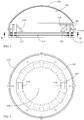
- FIG. 1 is a schematic view showing the main structure of the annular heat dissipation device (101), according to this invention.
- FIG. 2 is a cross sectional view of FIG. 1 taken alone an A-A line.
- FIG. 1 and FIG. 2 it mainly consists of:
- the two or more than two of the light emitting devices (110) arranged in a circular or polygonal means are annularly installed at the side of annular heat dissipation device to be installed with light emitting devices (102) of the lamp, and the light projection axial line of each light emitting device (110) is defined in a reverse direction which is 90 degree larger but 180 degree smaller relative to the preset final projecting direction of the lamp for illuminating light beams, so as to project light beams to the reflection device with concave sphere (103) installed on the inner side, upper side or the upward-inclined surface of the annular heat dissipation device (101), then reflected by the concave spherical reflection unit (104) of the reflection device with concave sphere (103) to a projection surface, and for being coaxial with the final projecting direction for illuminating light beams, the light beams of the light emitting devices (110) are reflected by the reflection device with concave sphere (103) then ref
- the annular-arranged lamp capable of backward projecting by concave sphere can be further formed in a fluid cooling type structure having flowpath therein.
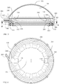
- FIG. 3 is a schematic structural view showing the fluid cooling type annular heat dissipation device assembly (200) having flowpath therein, according to this invention.
- FIG. 4 is a cross sectional view of FIG. 3 taken along a B-B line.
- FIG. 3 and FIG. 4 it mainly consists of:
- the upper end of the middle annular member (201) is installed with an upper annular member (202), and a leakage-proof pad (204) is provided therebetween;
- the lower end of the middle annular member (201) is installed with a lower annular member (203), and a leakage-proof pad (204) is provided therebetween;
- the mentioned fluid cooling type annular heat dissipation device assembly (200) includes an integrally-formed structure made of a heat conductive material in which the leakage-proof pad (204) is not provided;
- the two or more than two of the light emitting devices (110) arranged in a circular or polygonal means are annularly installed at the side of fluid cooling type annular heat dissipation device assembly to be installed with light emitting devices (302) of the lamp, and the light projection axial line of each light emitting device (110) is defined in a reverse direction which is 90 degree larger but 180 degree smaller relative to the preset final projecting direction of the lamp for illuminating light beams, so as to project light beams to the reflection device with concave sphere (103) installed on the inner side, upper side or the upward-inclined surface of the fluid cooling type annular heat dissipation device assembly (200), then reflected by the concave spherical reflection unit (104) of the reflection device with concave sphere (103) to a projection surface, and for being coaxial with the final projecting direction for illuminating light beams, the light beams of the light emitting devices (110) are reflected by the reflection device with con
- the mentioned light emitting device (110) is consisted of one or more than one of the followings, which include:
Landscapes
- Engineering & Computer Science (AREA)
- General Engineering & Computer Science (AREA)
- Non-Portable Lighting Devices Or Systems Thereof (AREA)
- Arrangement Of Elements, Cooling, Sealing, Or The Like Of Lighting Devices (AREA)
Abstract
Description
- This invention provides an annular-arranged lamp capable of backward projecting by concave sphere, in which two or more than two light emitting devices (110) arranged in a circular or polygonal means being annularly installed at the side of annular heat dissipation device to be installed with light emitting devices (102) of the lamp, and the light projecting axial line of each light emitting device (110) is projected towards a reflection device with concave sphere (103) disposed above the annular heat dissipation device (101), light beams of the light emitting devices (110) are reflected by the reflection device with concave sphere (103) then refracted to a preset projection range, thereby forming a unified light source.
- When a conventional lamp is configured by multiple light sources, there is a shortage of illumination deterioration due to uneven brightness formed at different locations. Such shortage shall be improved.
- This invention provides an annular-arranged lamp capable of backward projecting by concave sphere, in which two or more than two light emitting devices (110) arranged in a circular or polygonal means being annularly installed at the side of annular heat dissipation device to be installed with light emitting devices (102) of the lamp, the light projection axial line of each light emitting device (110) is defined in a reverse direction which is 90 degree larger but 180 degree smaller relative to the preset final projecting direction for illuminating light of the lamp for projecting towards a reflection device with concave sphere (103) disposed above the annular heat dissipation device (101), the project surface after being reflected by a concave spherical reflection unit (104) of the reflection device with concave sphere (103) is coaxial with the final projecting direction for illuminating light beams, light beams of the light emitting devices (110) are reflected by the reflection device with concave sphere (103) then refracted to a preset projection range, thereby forming a unified light source.
- According to a second aspect of the invention, an annular-arranged lamp comprising two or more light emitting devices, LEDs, arranged in a substantially circular or polygonal array arrangement; an annular heat dissipation device arranged in close proximity to and around the perimeter of said array of LEDs; a reflection member coupled to said annular heat dissipation device, the reflection member having a concave substantially hemispherical reflective surface on which lights emitted from each LED of said LED array are reflected and projected in a preset direction; and wherein each LED is arranged such that the axis of the light beam from said LED is at an angle of between 90 degrees and 180 degrees relative to said preset direction.
-
-
FIG. 1 is a schematic view showing the main structure of the annular heat dissipation device (101), according to this invention. -
FIG. 2 is a cross sectional view ofFIG. 1 taken alone an A-A line. -
FIG. 3 is a schematic structural view showing the fluid cooling type annular heat dissipation device assembly (200) having flowpath therein, according to this invention. -
FIG. 4 is a cross sectional view ofFIG. 3 taken along a B-B line. -
- 101 : Annular heat dissipation device
- 102 : A side of annular heat dissipation device to be installed with light emitting devices
- 103 : Reflection device with concave sphere
- 104 : Concave spherical reflection unit
- 110 : Light emitting device
- 111 : Light pervious protection sheet
- 112 : Fasten ring
- 113 : Elastic pad
- 200 : Fluid cooling type annular heat dissipation device assembly
- 201 : Middle annular member
- 202 : Upper annular member
- 203 : Lower annular member
- 204 : Leakage-proof pad
- 205 : Upper annular flowpath
- 206 : Lower annular flowpath
- 207 : Fluid pipe connector
- 208 : Upper/lower annular flowpath through hole
- 302 : A side of fluid cooling type heat dissipation device assembly to be installed with light emitting devices
- When a conventional lamp is configured by multiple light sources, there is a shortage of illumination deterioration due to uneven brightness formed at different locations. Such shortage shall be improved.
- This invention provides an annular-arranged lamp capable of backward projecting by concave sphere, in which two or more than two light emitting devices arranged in a circular or polygonal means being annularly installed at the side of annular heat dissipation device to be installed with light emitting devices of the lamp, the light projection axial line of each light emitting device is defined in a reverse direction which is 90 degree larger but 180 degree smaller relative to the preset final projecting direction for illuminating light of the lamp for projecting towards a reflection device with concave sphere disposed above the annular heat dissipation device, the project surface after being reflected by a concave spherical reflection unit of the reflection device with concave sphere is coaxial with the final projecting direction for illuminating light beams, light beams of the light emitting devices are reflected by the reflection device with concave sphere then refracted to a preset projection range, thereby forming a unified light source.
-
FIG. 1 is a schematic view showing the main structure of the annular heat dissipation device (101), according to this invention. -
FIG. 2 is a cross sectional view ofFIG. 1 taken alone an A-A line. - As shown
FIG. 1 and FIG. 2 , it mainly consists of: - -- Annular heat dissipation device (101): which is configured by an annular heat dissipation structure made of a heat conductive material, and combined with the reflection device with concave sphere (103), wherein the annular heat dissipation device (101) is provided with a side of annular heat dissipation device to be installed with light emitting devices (102) for the installation of two or more than two light emitting devices (110);
- -- The side of annular heat dissipation device to be installed with light emitting devices (102): which is defined at the inner side, upper side or an upward-inclined surface of the annular heat dissipation device (101) for the installation of two or more than two of the light emitting devices (110), for projecting light beams to a concave spherical reflection unit (104) of the reflection device with concave sphere (103);
- -- Reflection device with concave sphere (103): which is combined with the annular heat dissipation device (101), the top of the reflection device with concave sphere (103) is formed as a sphere, and the interior of the sphere is integrally formed with a concave spherical reflection unit (104) processed with a polishing or coating treatment, or a concave spherical reflection unit (104) having a high-performance reflection surface capable of being installed inside the top end of the reflection device with concave sphere (103) is separately manufactured to be assembled, the enclosure of the reflection device with concave sphere (103) is disposed at the top end and the periphery of the annular heat dissipation device (101), and the space defined between the annular bottom end thereof and the bottom end of the side of annular heat dissipation device to be installed with light emitting devices (102) is clamped with a light pervious protection sheet (111) through a fasten ring (112), and two sides of the light pervious protection sheet (111) are installed with elastic pads (113);
- -- Concave spherical reflection unit (104): which is constituted by a concave spherical reflection unit (104) integrally formed inside the reflection device with concave sphere (103) and processed with the polishing or coating treatment, or a concave spherical unit (104) having a high-performance reflection surface capable of being installed inside the top end of the reflection device with concave sphere (103) is separately manufactured to be assembled, and the concave spherical reflection unit (104) is equipped with a high-performance light reflection capability for reflecting the light beams from the light emitting devices (110) to the final projecting direction;
- The operations and functions of the assembly of the mentioned components are: the two or more than two of the light emitting devices (110) arranged in a circular or polygonal means are annularly installed at the side of annular heat dissipation device to be installed with light emitting devices (102) of the lamp, and the light projection axial line of each light emitting device (110) is defined in a reverse direction which is 90 degree larger but 180 degree smaller relative to the preset final projecting direction of the lamp for illuminating light beams, so as to project light beams to the reflection device with concave sphere (103) installed on the inner side, upper side or the upward-inclined surface of the annular heat dissipation device (101), then reflected by the concave spherical reflection unit (104) of the reflection device with concave sphere (103) to a projection surface, and for being coaxial with the final projecting direction for illuminating light beams, the light beams of the light emitting devices (110) are reflected by the reflection device with concave sphere (103) then refracted to the preset projection range, thereby forming a unified light source;
- According to this invention, the annular-arranged lamp capable of backward projecting by concave sphere can be further formed in a fluid cooling type structure having flowpath therein.
-
FIG. 3 is a schematic structural view showing the fluid cooling type annular heat dissipation device assembly (200) having flowpath therein, according to this invention. -
FIG. 4 is a cross sectional view ofFIG. 3 taken along a B-B line. - As shown in
FIG. 3 and FIG. 4 , it mainly consists of: - -- Fluid cooling type annular heat dissipation device assembly (200): which is assembled by multiple layers of annular members made of heat conductive materials for structuring the fluid cooling type annular heat dissipation device assembly having fluid flowpath, and is combined with the reflection device with concave sphere (103), the fluid cooling type annular heat dissipation device assembly (200) is formed with a side of fluid cooling type annular heat dissipation device assembly to be installed with light emitting devices (302) for the installation of two or more than two of the light emitting devices (110), wherein a middle annular member (201) is respectively installed with an upper annular flowpath (205) and a lower annular flowpath (206) at the upper and lower ends thereof, and an upper/lower annular flowpath through hole (208) is formed at the distal flowpaths ends defined at the same location angles of the upper annular flowpath (205) and the lower annular flowpath (206) for the purpose of communication;
- The upper end of the middle annular member (201) is installed with an upper annular member (202), and a leakage-proof pad (204) is provided therebetween;
- The lower end of the middle annular member (201) is installed with a lower annular member (203), and a leakage-proof pad (204) is provided therebetween;
- By tightening the middle annular member (201), the upper annular member (202) and the lower annular member (203), flowpaths respectively in the clockwise and the counterclockwise directions are formed and respectively leaded towards a fluid pipe connector (207) for connecting with the exterior, so as to allow the fluid to flow in and flow out;
- The mentioned fluid cooling type annular heat dissipation device assembly (200) includes an integrally-formed structure made of a heat conductive material in which the leakage-proof pad (204) is not provided;
- -- The side of fluid cooling type annular heat dissipation device assembly to be installed with light emitting devices (302): the inner side, or the upper side or an upward-inclined surface of the fluid cooling type annular heat dissipation device assembly (200) is installed with two or more than two of the light emitting devices (110) for projecting light beams to the concave spherical reflection unit (104) of the reflection device with concave sphere (103);
- -- Reflection device with concave sphere (103): which is combined with the fluid cooling type annular heat dissipation device assembly (200), the top of the reflection device with concave sphere (103) is formed as a sphere, and the interior of the sphere is integrally formed with a concave spherical unit (104) processed with a polishing or coating treatment, or a concave spherical unit (104) having a high-performance reflection surface capable of being installed inside the top end of the reflection device with concave sphere (103) is separately manufactured to be assembled, the enclosure of the reflection device with concave sphere (103) is disposed at the top end and the periphery of the fluid cooling type annular heat dissipation device assembly (200), and the space defined between the annular bottom end thereof and the bottom end of the side of annular heat dissipation device to be installed with light emitting devices (102) is clamped with a light pervious protection sheet (111) through a fasten ring (112), and two sides of the light pervious protection sheet (111) are installed with elastic pads (113);
- -- Concave spherical reflection unit (104): which is constituted by a concave spherical reflection unit (104) integrally formed inside the reflection device with concave sphere (103) and processed with the polishing or coating treatment, or a concave spherical unit (104) having a high-performance reflection surface capable of being installed inside the top end of the reflection device with concave sphere (103) is separately manufactured to be assembled, and the concave spherical reflection unit (104) is equipped with a high-performance light reflection capability for reflecting the light beams from the light emitting devices (110) to the final projecting direction;
- The operations and functions of the assembly of the mentioned components are: the two or more than two of the light emitting devices (110) arranged in a circular or polygonal means are annularly installed at the side of fluid cooling type annular heat dissipation device assembly to be installed with light emitting devices (302) of the lamp, and the light projection axial line of each light emitting device (110) is defined in a reverse direction which is 90 degree larger but 180 degree smaller relative to the preset final projecting direction of the lamp for illuminating light beams, so as to project light beams to the reflection device with concave sphere (103) installed on the inner side, upper side or the upward-inclined surface of the fluid cooling type annular heat dissipation device assembly (200), then reflected by the concave spherical reflection unit (104) of the reflection device with concave sphere (103) to a projection surface, and for being coaxial with the final projecting direction for illuminating light beams, the light beams of the light emitting devices (110) are reflected by the reflection device with concave sphere (103) then refracted to the preset projection range, thereby forming a unified light source;
- According to the annular-arranged lamp capable of backward projecting by concave sphere provided by this invention, the mentioned light emitting device (110) is consisted of one or more than one of the followings, which include:
- 1) DC light emitting diode (LED);
- 2) AC light emitting diode (LED);
- 3) Gas lamp set;
- 4) Fluorescent lamp;
- 5) Lamp bulb.
Claims (2)
- An annular-arranged lamp capable of backward projecting by concave sphere, in which two or more than two light emitting devices arranged in a circular or polygonal means being annularly installed at the side of annular heat dissipation device to be installed with light emitting devices of the lamp, the light projection axial line of each light emitting device is defined in a reverse direction which is 90 degree larger but 180 degree smaller relative to the preset final projecting direction for illuminating light of the lamp for projecting towards a reflection device with concave sphere disposed above the annular heat dissipation device, the project surface after being reflected by a concave spherical reflection unit of the reflection device with concave sphere is coaxial with the final projecting direction for illuminating light beams, light beams of the light emitting devices are reflected by the reflection device with concave sphere then refracted to a preset projection range, thereby forming a unified light source, and it mainly consists of:-- Annular heat dissipation device (101): which is configured by an annular heat dissipation structure made of a heat conductive material, and combined with the reflection device with concave sphere (103), wherein the annular heat dissipation device (101) is provided with a side of annular heat dissipation device to be installed with light emitting devices (102) for the installation of two or more than two light emitting devices (110);-- The side of annular heat dissipation device to be installed with light emitting devices (102): which is defined at the inner side, upper side or an upward-inclined surface of the annular heat dissipation device (101) for the installation of two or more than two of the light emitting devices (110), for projecting light beams to a concave spherical reflection unit (104) of the reflection device with concave sphere (103);-- Reflection device with concave sphere (103): which is combined with the annular heat dissipation device (101), the top of the reflection device with concave sphere (103) is formed as a sphere, and the interior of the sphere is integrally formed with a concave spherical reflection unit (104) processed with a polishing or coating treatment, or a concave spherical reflection unit (104) having a high-performance reflection surface capable of being installed inside the top end of the reflection device with concave sphere (103) is separately manufactured to be assembled, the enclosure of the reflection device with concave sphere (103) is disposed at the top end and the periphery of the annular heat dissipation device (101), and the space defined between the annular bottom end thereof and the bottom end of the side of annular heat dissipation device to be installed with light emitting devices (102) is clamped with a light pervious protection sheet (111) through a fasten ring (112), and two sides of the light pervious protection sheet (111) are installed with elastic pads (113);-- Concave spherical reflection unit (104): which is constituted by a concave spherical reflection unit (104) integrally formed inside the reflection device with concave sphere (103) and processed with the polishing or coating treatment, or a concave spherical unit (104) having a high-performance reflection surface capable of being installed inside the top end of the reflection device with concave sphere (103) is separately manufactured to be assembled, and the concave spherical reflection unit (104) is equipped with a high-performance light reflection capability for reflecting the light beams from the light emitting devices (110) to the final projecting direction;The operations and functions of the assembly of the mentioned components are: the two or more than two of the light emitting devices (110) arranged in a circular or polygonal means are annularly installed at the side of annular heat dissipation device to be installed with light emitting devices (102) of the lamp, and the light projection axial line of each light emitting device (110) is defined in a reverse direction which is 90 degree larger but 180 degree smaller relative to the preset final projecting direction of the lamp for illuminating light beams, so as to project light beams to the reflection device with concave sphere (103) installed on the inner side, upper side or the upward-inclined surface of the annular heat dissipation device (101), then reflected by the concave spherical reflection unit (104) of the reflection device with concave sphere (103) to a projection surface, and for being coaxial with the final projecting direction for illuminating light beams, the light beams of the light emitting devices (110) are reflected by the reflection device with concave sphere (103) then refracted to the preset projection range, thereby forming a unified light source.
- An annular-arranged lamp capable of backward projecting by concave sphere as claimed in claim 1, wherein the mentioned light emitting device (110) is consisted of one or more than one of the followings, which include:1) DC light emitting diode (LED);2) AC light emitting diode (LED);3) Gas lamp set;4) Fluorescent lamp;5) Lamp bulb.
Applications Claiming Priority (2)
| Application Number | Priority Date | Filing Date | Title |
|---|---|---|---|
| US13/219,791 US8568000B2 (en) | 2011-08-29 | 2011-08-29 | Annular-arranged lamp capable of backward projecting by concave sphere |
| EP12181158.2A EP2565528B1 (en) | 2011-08-29 | 2012-08-21 | Annular-arranged lamp capable of backward projecting by concave sphere |
Related Parent Applications (1)
| Application Number | Title | Priority Date | Filing Date |
|---|---|---|---|
| EP12181158.2A Division EP2565528B1 (en) | 2011-08-29 | 2012-08-21 | Annular-arranged lamp capable of backward projecting by concave sphere |
Publications (1)
| Publication Number | Publication Date |
|---|---|
| EP3232120A1 true EP3232120A1 (en) | 2017-10-18 |
Family
ID=47224968
Family Applications (2)
| Application Number | Title | Priority Date | Filing Date |
|---|---|---|---|
| EP12181158.2A Active EP2565528B1 (en) | 2011-08-29 | 2012-08-21 | Annular-arranged lamp capable of backward projecting by concave sphere |
| EP17170081.8A Withdrawn EP3232120A1 (en) | 2011-08-29 | 2012-08-21 | Annular-arranged lamp capable of backward projecting by concave sphere |
Family Applications Before (1)
| Application Number | Title | Priority Date | Filing Date |
|---|---|---|---|
| EP12181158.2A Active EP2565528B1 (en) | 2011-08-29 | 2012-08-21 | Annular-arranged lamp capable of backward projecting by concave sphere |
Country Status (8)
| Country | Link |
|---|---|
| US (2) | US8568000B2 (en) |
| EP (2) | EP2565528B1 (en) |
| JP (2) | JP6140406B2 (en) |
| CN (1) | CN102966863B (en) |
| AU (1) | AU2012216484B2 (en) |
| CA (1) | CA2787399C (en) |
| ES (1) | ES2627795T3 (en) |
| TW (2) | TWI586920B (en) |
Families Citing this family (5)
| Publication number | Priority date | Publication date | Assignee | Title |
|---|---|---|---|---|
| US8985816B2 (en) * | 2012-06-01 | 2015-03-24 | RAB Lighting Inc. | Light fixture with central lighting housing and peripheral cooling housing |
| CN104235763B (en) * | 2013-06-17 | 2017-01-18 | 展晶科技(深圳)有限公司 | Light emitting diode lighting device |
| WO2015013857A1 (en) * | 2013-07-29 | 2015-02-05 | Lee Chun-Yu | Dual-sided transparent led lamp |
| CN110822353A (en) * | 2019-11-15 | 2020-02-21 | 徐州达娇物资贸易有限公司 | Cast high-temperature-resistant LED explosion-proof lamp |
| CN113570886A (en) * | 2021-07-26 | 2021-10-29 | 江苏坤博交通科技有限公司 | Split type traffic signal lamp |
Citations (4)
| Publication number | Priority date | Publication date | Assignee | Title |
|---|---|---|---|---|
| JP2007080533A (en) * | 2005-09-09 | 2007-03-29 | Matsushita Electric Works Ltd | LED lighting fixtures |
| WO2007130536A2 (en) * | 2006-05-05 | 2007-11-15 | Cree Led Lighting Solutions, Inc. | Lighting device |
| US20090034252A1 (en) * | 2007-08-02 | 2009-02-05 | Engel Hartmut S | Luminaire |
| EP2278214A1 (en) * | 2009-07-23 | 2011-01-26 | LG Innotek Co., Ltd. | Light emitting device |
Family Cites Families (34)
| Publication number | Priority date | Publication date | Assignee | Title |
|---|---|---|---|---|
| JPH024401Y2 (en) * | 1985-05-02 | 1990-02-01 | ||
| DE3929955A1 (en) * | 1989-09-08 | 1991-03-14 | Inotec Gmbh Ges Fuer Innovativ | LIGHT SPOTLIGHTS |
| IT1252026B (en) * | 1991-11-29 | 1995-05-27 | LIGHTING APPARATUS IN PARTICULAR FOR ENVIRONMENTS WITHOUT NATURAL LIGHT | |
| US5475571A (en) * | 1994-03-30 | 1995-12-12 | Ford Motor Company | Ring Light collector |
| US5924785A (en) * | 1997-05-21 | 1999-07-20 | Zhang; Lu Xin | Light source arrangement |
| JP3173453B2 (en) * | 1998-03-13 | 2001-06-04 | スタンレー電気株式会社 | Signal lights for vehicles |
| US6076948A (en) * | 1998-10-28 | 2000-06-20 | K. W. Muth Company, Inc. | Electromagnetic radiation emitting or receiving assembly |
| JP4010084B2 (en) * | 1999-10-21 | 2007-11-21 | 市光工業株式会社 | Compact light source module and light source unit |
| DE20002565U1 (en) * | 2000-02-14 | 2001-06-28 | Zumtobel Staff Ges.M.B.H., Dornbirn | LED arrangement with reflector |
| US6840652B1 (en) * | 2001-07-31 | 2005-01-11 | Hi-Lite Safety Systems, L.C. | Lighting enhanced by magnified reflective surfaces |
| US6871993B2 (en) * | 2002-07-01 | 2005-03-29 | Accu-Sort Systems, Inc. | Integrating LED illumination system for machine vision systems |
| JP4371733B2 (en) * | 2003-08-21 | 2009-11-25 | 三菱電機株式会社 | Surface light source device |
| JP4804429B2 (en) * | 2003-12-05 | 2011-11-02 | 三菱電機株式会社 | Light emitting device and lighting apparatus using the same |
| US7559664B1 (en) * | 2004-12-27 | 2009-07-14 | John V. Walleman | Low profile backlighting using LEDs |
| JP2006236984A (en) * | 2005-01-25 | 2006-09-07 | Showa Denko Kk | Light source cooling device |
| US7473019B2 (en) * | 2005-09-29 | 2009-01-06 | Osram Opto Semiconductors Gmbh | Lighting apparatus |
| TWI294023B (en) * | 2006-03-17 | 2008-03-01 | Ind Tech Res Inst | Reflective illumination device |
| US20070279910A1 (en) * | 2006-06-02 | 2007-12-06 | Gigno Technology Co., Ltd. | Illumination device |
| WO2008022065A2 (en) * | 2006-08-11 | 2008-02-21 | Light Prescriptions Innovators, Llc | Led luminance-enhancement and color-mixing by rotationally multiplexed beam-combining |
| TW200839140A (en) * | 2007-03-27 | 2008-10-01 | Ama Precision Inc | LED table lamp |
| US7654709B2 (en) * | 2007-03-30 | 2010-02-02 | Sportlite, Inc. | Compact fluorescent lamp high bay luminaire |
| EP2843464A1 (en) * | 2007-05-29 | 2015-03-04 | Koninklijke Philips N.V. | Lighting device having a light exit window |
| US7980728B2 (en) * | 2008-05-27 | 2011-07-19 | Abl Ip Holding Llc | Solid state lighting using light transmissive solid in or forming optical integrating volume |
| JP2009289709A (en) * | 2008-06-02 | 2009-12-10 | Toshiba Lighting & Technology Corp | Ceiling direct attachment type illumination device and illumination device |
| CN101614362B (en) * | 2008-06-27 | 2012-06-13 | 富准精密工业(深圳)有限公司 | LED lamp |
| CN101660715B (en) * | 2008-08-25 | 2013-06-05 | 富准精密工业(深圳)有限公司 | Light-emitting diode lamp |
| JP2012526347A (en) * | 2009-05-07 | 2012-10-25 | コーニンクレッカ フィリップス エレクトロニクス エヌ ヴィ | Lighting device with phosphor and dichroic filter |
| US8651692B2 (en) * | 2009-06-18 | 2014-02-18 | Intematix Corporation | LED based lamp and light emitting signage |
| EP2863117B1 (en) * | 2009-11-09 | 2016-07-13 | LG Innotek Co., Ltd. | Lighting device |
| TW201120376A (en) * | 2009-12-11 | 2011-06-16 | Power Light Tech Co Ltd | Reflection type light-emitting assembly |
| JP4786750B2 (en) * | 2010-03-12 | 2011-10-05 | シャープ株式会社 | Lighting device |
| US8297798B1 (en) * | 2010-04-16 | 2012-10-30 | Cooper Technologies Company | LED lighting fixture |
| US8419203B1 (en) * | 2010-09-03 | 2013-04-16 | Rockwell Collins, Inc. | Single card multi mode LCD backlight |
| JP3168300U (en) * | 2011-01-26 | 2011-06-09 | 日本発條株式会社 | Floodlight waterproof structure |
-
2011
- 2011-08-29 US US13/219,791 patent/US8568000B2/en active Active
- 2011-09-21 TW TW100133862A patent/TWI586920B/en active
- 2011-09-21 TW TW100217637U patent/TWM437915U/en unknown
-
2012
- 2012-08-21 CA CA2787399A patent/CA2787399C/en active Active
- 2012-08-21 ES ES12181158.2T patent/ES2627795T3/en active Active
- 2012-08-21 EP EP12181158.2A patent/EP2565528B1/en active Active
- 2012-08-21 EP EP17170081.8A patent/EP3232120A1/en not_active Withdrawn
- 2012-08-22 CN CN201210301409.8A patent/CN102966863B/en active Active
- 2012-08-28 AU AU2012216484A patent/AU2012216484B2/en active Active
- 2012-08-29 JP JP2012188517A patent/JP6140406B2/en active Active
-
2013
- 2013-09-25 US US14/036,266 patent/US8956016B2/en active Active
-
2017
- 2017-04-28 JP JP2017089483A patent/JP2017152399A/en active Pending
Patent Citations (4)
| Publication number | Priority date | Publication date | Assignee | Title |
|---|---|---|---|---|
| JP2007080533A (en) * | 2005-09-09 | 2007-03-29 | Matsushita Electric Works Ltd | LED lighting fixtures |
| WO2007130536A2 (en) * | 2006-05-05 | 2007-11-15 | Cree Led Lighting Solutions, Inc. | Lighting device |
| US20090034252A1 (en) * | 2007-08-02 | 2009-02-05 | Engel Hartmut S | Luminaire |
| EP2278214A1 (en) * | 2009-07-23 | 2011-01-26 | LG Innotek Co., Ltd. | Light emitting device |
Also Published As
| Publication number | Publication date |
|---|---|
| JP6140406B2 (en) | 2017-05-31 |
| TW201309970A (en) | 2013-03-01 |
| AU2012216484B2 (en) | 2015-10-22 |
| TWM437915U (en) | 2012-09-21 |
| US8568000B2 (en) | 2013-10-29 |
| EP2565528B1 (en) | 2017-05-10 |
| US20140022785A1 (en) | 2014-01-23 |
| CA2787399C (en) | 2019-12-10 |
| CN102966863B (en) | 2016-11-09 |
| US8956016B2 (en) | 2015-02-17 |
| CA2787399A1 (en) | 2013-02-28 |
| EP2565528A2 (en) | 2013-03-06 |
| EP2565528A3 (en) | 2014-06-04 |
| ES2627795T3 (en) | 2017-07-31 |
| TWI586920B (en) | 2017-06-11 |
| JP2013048093A (en) | 2013-03-07 |
| JP2017152399A (en) | 2017-08-31 |
| US20130051007A1 (en) | 2013-02-28 |
| CN102966863A (en) | 2013-03-13 |
| AU2012216484A1 (en) | 2013-03-21 |
Similar Documents
| Publication | Publication Date | Title |
|---|---|---|
| US8388193B2 (en) | Lens with TIR for off-axial light distribution | |
| AU2009249557A1 (en) | Recessed LED lighting fixture | |
| US10077883B2 (en) | Illumination device with optical units including spiral structure optical unit and illumination device having the same | |
| US8956016B2 (en) | Annular-arranged lamp capable of backward projecting by concave sphere | |
| US8292464B2 (en) | LED lamp | |
| TW201422974A (en) | Light emitting diode bulb | |
| TW201416606A (en) | Light emitting diode bulb | |
| JP2009009870A (en) | Light source unit and light bulb shaped lamp | |
| JP6241601B2 (en) | Lighting device | |
| TW201339502A (en) | A light fixture | |
| TWM457847U (en) | Lighting device having a widely light emitting angle | |
| CN105402656B (en) | LED spotlight structure | |
| JP6429672B2 (en) | Light emitting device and lighting apparatus using the same | |
| JP4614351B2 (en) | Vehicle lamp | |
| TWM445676U (en) | Lighting device | |
| JP2016219378A (en) | Lighting equipment and light source cover | |
| TWI457515B (en) | Lamp | |
| JP2013143399A (en) | Light-emitting diode lamp | |
| JP5653396B2 (en) | Light emitting device | |
| WO2012160635A1 (en) | Illumination device | |
| CN104948944B (en) | Wide-angle LED lamp | |
| JP6393942B2 (en) | lighting equipment | |
| JP2009289440A (en) | Luminaire | |
| TWM459345U (en) | LED sphere bulb lamp | |
| TWM524428U (en) | Lighting device and optical member thereof |
Legal Events
| Date | Code | Title | Description |
|---|---|---|---|
| PUAI | Public reference made under article 153(3) epc to a published international application that has entered the european phase |
Free format text: ORIGINAL CODE: 0009012 |
|
| STAA | Information on the status of an ep patent application or granted ep patent |
Free format text: STATUS: REQUEST FOR EXAMINATION WAS MADE |
|
| 17P | Request for examination filed |
Effective date: 20170509 |
|
| AC | Divisional application: reference to earlier application |
Ref document number: 2565528 Country of ref document: EP Kind code of ref document: P |
|
| AK | Designated contracting states |
Kind code of ref document: A1 Designated state(s): AL AT BE BG CH CY CZ DE DK EE ES FI FR GB GR HR HU IE IS IT LI LT LU LV MC MK MT NL NO PL PT RO RS SE SI SK SM TR |
|
| STAA | Information on the status of an ep patent application or granted ep patent |
Free format text: STATUS: THE APPLICATION HAS BEEN WITHDRAWN |
|
| 18W | Application withdrawn |
Effective date: 20180601 |