EP3232047A1 - High pressure fuel pump - Google Patents
High pressure fuel pump Download PDFInfo
- Publication number
- EP3232047A1 EP3232047A1 EP17165362.9A EP17165362A EP3232047A1 EP 3232047 A1 EP3232047 A1 EP 3232047A1 EP 17165362 A EP17165362 A EP 17165362A EP 3232047 A1 EP3232047 A1 EP 3232047A1
- Authority
- EP
- European Patent Office
- Prior art keywords
- face
- shoe
- leading
- pump
- trailing
- Prior art date
- Legal status (The legal status is an assumption and is not a legal conclusion. Google has not performed a legal analysis and makes no representation as to the accuracy of the status listed.)
- Withdrawn
Links
Images

Classifications
-
- F—MECHANICAL ENGINEERING; LIGHTING; HEATING; WEAPONS; BLASTING
- F02—COMBUSTION ENGINES; HOT-GAS OR COMBUSTION-PRODUCT ENGINE PLANTS
- F02M—SUPPLYING COMBUSTION ENGINES IN GENERAL WITH COMBUSTIBLE MIXTURES OR CONSTITUENTS THEREOF
- F02M59/00—Pumps specially adapted for fuel-injection and not provided for in groups F02M39/00 -F02M57/00, e.g. rotary cylinder-block type of pumps
- F02M59/02—Pumps specially adapted for fuel-injection and not provided for in groups F02M39/00 -F02M57/00, e.g. rotary cylinder-block type of pumps of reciprocating-piston or reciprocating-cylinder type
- F02M59/10—Pumps specially adapted for fuel-injection and not provided for in groups F02M39/00 -F02M57/00, e.g. rotary cylinder-block type of pumps of reciprocating-piston or reciprocating-cylinder type characterised by the piston-drive
-
- F—MECHANICAL ENGINEERING; LIGHTING; HEATING; WEAPONS; BLASTING
- F02—COMBUSTION ENGINES; HOT-GAS OR COMBUSTION-PRODUCT ENGINE PLANTS
- F02M—SUPPLYING COMBUSTION ENGINES IN GENERAL WITH COMBUSTIBLE MIXTURES OR CONSTITUENTS THEREOF
- F02M59/00—Pumps specially adapted for fuel-injection and not provided for in groups F02M39/00 -F02M57/00, e.g. rotary cylinder-block type of pumps
- F02M59/02—Pumps specially adapted for fuel-injection and not provided for in groups F02M39/00 -F02M57/00, e.g. rotary cylinder-block type of pumps of reciprocating-piston or reciprocating-cylinder type
- F02M59/10—Pumps specially adapted for fuel-injection and not provided for in groups F02M39/00 -F02M57/00, e.g. rotary cylinder-block type of pumps of reciprocating-piston or reciprocating-cylinder type characterised by the piston-drive
- F02M59/102—Mechanical drive, e.g. tappets or cams
-
- F—MECHANICAL ENGINEERING; LIGHTING; HEATING; WEAPONS; BLASTING
- F04—POSITIVE - DISPLACEMENT MACHINES FOR LIQUIDS; PUMPS FOR LIQUIDS OR ELASTIC FLUIDS
- F04B—POSITIVE-DISPLACEMENT MACHINES FOR LIQUIDS; PUMPS
- F04B1/00—Multi-cylinder machines or pumps characterised by number or arrangement of cylinders
- F04B1/04—Multi-cylinder machines or pumps characterised by number or arrangement of cylinders having cylinders in star- or fan-arrangement
- F04B1/0404—Details or component parts
- F04B1/0439—Supporting or guiding means for the pistons
Definitions
- the present invention relates generally to the field of high pressure fuel pumps. More particularly, but not exclusively, the present invention concerns an adapted shoe for high pressure diesel fuel pumps.
- a typical high pressure diesel fuel pump adopting a roller-shoe arrangement as part of the drivetrain comprises a plunger 1 extending from a hydraulic head along a pumping axis A-A'.
- a plunger return spring is seated around the head and extends to the top of a spring seat fixed near a lower end of the plunger 1.
- the lower end of the plunger 1 contacts an upper face 2a of a shoe 2.
- the shoe 2 slides within an axial bore 4 (disposed along the pumping axis A-A') of a shoe guide 3.
- a roller 5 is mounted and retained within an aperture provided at a lower end of the shoe 3 and slides within the bore 4 with the shoe 3.
- the roller 5 contacts a surface of a cam 6, which is driven to rotate in direction D by a rotating driveshaft (not shown) to provide upward sliding motion along the pumping axis A-A'.
- a 'leading' or 'trust' face 2a hereafter referred to as the leading face
- BDC bottom dead centre
- the shoe 2 is generally in full contact with a respective inside wall 4a of the bore 4.
- the shoe 2 tilts rapidly within the bore 4 of the shoe guide 3, shifting a lower edge of the leading face 2a away from the inside wall 4a of the bore 4.
- the angle of the leading face 2a relative to the inside wall 4a generates a void between the leading face 2a and the respective inside wall 4a of the bore 4, which forms a low pressure region and results in cavitation of the leading face 2a and/ or the inside wall 4a of the bore 4.
- the tilt causes the shoe 2 to 'run' on an upper edge of the leading face 2a against the respective inside wall 4a, which results in deterioration of the integrity of that upper edge.
- TDC top dead centre
- the shoe 2 tilts swinging a lower edge of a 'trailing' face 2b away from the opposite inside wall 4b. Also, the shoe 2 is rapidly moves from bore inside wall 4b towards bore inside wall 4a, creating a void between the trailing face 2b and the respective inside wall 4b, resulting in low pressure and cavitation as before. This time, the tilt causes the shoe 2 to 'run' on an upper edge of the trailing face 2b against the respective inside wall 4b, which results in deterioration of the integrity of that upper edge.
- BDC bottom dead centre
- a high pressure fuel pump adapted to be actuated by a rotating cam.
- the pump has a pump head wherein a plunger is arranged for reciprocating linear movement along the pumping axis within a pumping chamber.
- the plunger performing a pumping cycle translating between TDC and BDC in a filling stroke and a thereafter a pumping stroke.
- the pump is further provided with a shoe guided in a shoe guide, the shoe having an upper face in contact with the plunger, an opposed lower face shaped to receiving a roller for contact with the cam and, between said faces, a side leading face sliding along a side internal leading wall of said guide and, an opposed side trailing face sliding along a side internal trailing wall of said guide (20).
- At least one side leading or trailing face of the shoe comprises a convex curve thereon.
- 'side face' what is meant is a face of the shoe that is not a face open to said roller; and by 'leading face' is meant a side face of the shoe that is biased towards a corresponding internal side wall of the shoe guide during the pumping stroke caused by the direction of rotation of the cam, but biased away from that internal side wall during the filling stroke.
- 'trailing face' is meant a side face of the shoe opposite the leading face.
- the convex curve on the side face functions to prevent the shoe from running on an upper edge, since the curve encourages the shoe to roll onto the side face during the pumping stroke.
- the curve also reduces the volume of the void that is created between the side face and the corresponding shoe guide inner wall even at a high tilting angle. In turn, this reduces cavitation.
- the shoe is provided with a cavity, shaped in its lower face, the roller being mounted within said cavity.
- leading face and the trailing face of the shoe may both comprise a convex curve thereon.
- leading and trailing faces may have different profiles, in an embodiment the leading and of the trailing faces are symmetrical relative to the pumping axis, the convex curves matching together. Alternatively in another embodiment, the leading and trailing faces are symmetrical relative to an axis perpendicular to the pumping axis.
- the convex curve extends across at least a part of the respective side face between a top edge of said side face with said upper face to, a bottom edge of said side face with said lower face.
- the convex curve extends from the top edge or from the bottom edge of the respective side face.
- the convex curve may extend across the whole of the respective side face from the top edge to the bottom edge thereof.
- the convex curve comprises a consistent curve profile across the respective side leading or trailing face.
- 'consistent' is meant that the convex curvature of the face is smooth, constant or evolving slowly, without accident or rough changes. The curvature is uniform or, if nonuniform it is gradually shallowing.
- the convex curve comprises a radius of between 100 mm and 400 mm, and preferably of approximately 200 mm.
- the shoe may comprise a chamfered upper edge.
- the chamfered upper edge comprises at least two opposing sloped portions extending between the upper face flat plunger-engaging surface and respective side faces of the shoe.
- the pump is a diesel pump.
- the invention further extends to a shoe adapted to be arranged in a high pressure fuel pump as described above.
- a high pressure diesel fuel pump comprises a pumping assembly (not shown) comprising a plunger (not shown) extending from a pump head (not shown) along a pumping axis A-A'.
- a shoe 10 is in contact with a lower end of the plunger and a roller 11 is mounted within a cavity 13 of the shoe 10 for contact with a cam 2.
- the pump also comprises a shoe guide 20 mounted within a guide chamber (not shown) of the housing substantially between the cam 2 and the plunger and adapted to receive the shoe 10 and roller 11 within a bore 23 thereof, wherein the plunger is arranged for reciprocating linear movement along the pumping axis A-A' within a pumping chamber (not shown) of the housing.
- One side face 15a, 15b of the shoe 10 comprises a convex curve thereon.
- the shoe 10 comprises an upper face 12a and a lower face 12b.
- the cavity 13 for the roller 11 is provided in the lower face 12b, whilst a plunger contact surface is provided by the upper face 12a.
- Between the upper face 12a and the lower face 12b are a pair of opposing end faces 14a and 14b (only one shown) and a pair of opposing side faces comprising a leading face 15a and a trailing face 15b.
- the cavity 13 for the roller 11 extends between the pair of end faces 14a and is open to both end faces 14a.
- the leading face 15a and the trailing face 15b are closed to the cavity 13.
- the shoe 10 is generally cuboidal, with the leading face 15a and the trailing face 15b being elongate compared with the end faces 14a. At the junction between the leading face 15a and the trailing face 15b with the respective end faces 14a, the shoe 10 comprises blunted corners 18.
- the shoe 10 is sized for a sliding fit with the bore 23 of the shoe guide 20 between two pairs of retaining walls, comprising end retaining walls (not shown) and side retaining walls 25a, 25b.
- the cavity 13 comprises a half-cylindrical open-ended aperture sized to accommodate the rotating roller 11.
- both the leading face 15a and the trailing face 15b comprise a convex curve.
- the curve extends substantially from the upper face 12a of the shoe 10 to the lower face 12b of the shoe 10.
- the curve also extends substantially across the whole of the respective leading face 15b and trailing face 15b between the two end faces 14a, 14b of the shoe 10 and as such covers substantially the whole of the respective leading face 15a and the trailing face 15b.
- the curve may either: only extend from the upper face 12a of the shoe 10 to part way down the respective leading face 15a or the trailing face 15b, and as such may cover from at least 50% of a depth of the respective leading face 15a or the trailing face 15b; and/or only extend from the across a portion of the respective leading face 15a or the trailing face 15b of the shoe 10 between the two end faces 14a, 14b, and as such may cover from at least 50% of a length of the respective leading face 15a or the trailing face 15b.
- the curve on the leading face 15a and the trailing face 15b comprise a uniform curve-profile.
- the curve profile comprises a curve with a radius of approximately 200 mm thereacross.
- the curve profile may be non-uniform and could, for example comprise a gradually shallowing curve across the depth and/or the length of the respective leading face 15a or the trailing face 15b.
- a 'leading' face is characterised by the direction D of rotation of the cam 2, as the side face of the shoe 10 that is biased towards a corresponding internal wall of the bore 25 of the shoe guide 20 during the pumping stroke, but biased away from that internal wall during the filling stroke, in the Figures, the leading face has been designated as side face 15a and the leading internal wall as 25a where the direction D is clockwise.
- either of said side faces 15a, 15b may be configured to comprise the leading face of the shoe 10 and either of said walls 25a, 25b of the guide 20 may comprise the corresponding leading internal wall, with the remaining opposing side face 15a, 15b and corresponding internal wall 25a, 25b taking on the function of a trailing face and trailing internal wall. Accordingly, in the event that the direction D of rotation of the cam 2 was reversed, side face 15b would be the leading face and internal wall 25b would be the leading internal wall.
- the shoe 10 is disposed in the bore 23 of the shoe guide 20 such that the end faces 14a of the shoe 10 contact the internal end walls and the leading face 15a and the trailing face 15b contact the internal leading wall 25a and the internal trailing wall 25b respectively.
- the cavity 13 for the roller 11 is orientated downwardly towards the cam 2. Therefore, the convex curve of each of the leading face 15a and the trailing face 15b span substantially across an entire width of the internal leading wall 25a and the internal trailing wall 25b respectively.
- both side faces 15a, 15b incorporate such a convex curve since both side faces 15a, 15b are prone to cavitation during the process pumping and filling stroke respectively.
- both side faces 15a, 15b are prone to cavitation during the process pumping and filling stroke respectively.
- either side face 15a, 15b is capable of performing as the leading face and as such, the shoe 10 can be used in either of two orientations and still function as intended, which minimises assembly issues. It is to be appreciated therefore, that only one of said side faces 15a, 15b may be provided with the convex curve to be orientated as the leading face during assembly.
- the leading face 15a is tilted to lean towards inside wall 25a.
- the curve on the leading face 15a prevents the shoe 10 from running on the top edge of the leading face 15a.
- the curve on the leading face 15a minimises the space between itself and the inside wall 25a caused by the tilt.
- the curve on the opposite trailing face 15b minimises the space created between itself and the inside wall 25b. Where spaces are reduced, cavitation is reduced.
- 'high pressure fuel pump' it is intended to mean a pump operating at 2000 bars and above which is typically the case for a diesel pump but, despite this, the invention can be utilized for another type of pump such as a gasoline pump.
Landscapes
- Engineering & Computer Science (AREA)
- Mechanical Engineering (AREA)
- General Engineering & Computer Science (AREA)
- Chemical & Material Sciences (AREA)
- Combustion & Propulsion (AREA)
- Fuel-Injection Apparatus (AREA)
Abstract
Description
- The present invention relates generally to the field of high pressure fuel pumps. More particularly, but not exclusively, the present invention concerns an adapted shoe for high pressure diesel fuel pumps.
- As shown in
Figure 1 , a typical high pressure diesel fuel pump adopting a roller-shoe arrangement as part of the drivetrain, comprises aplunger 1 extending from a hydraulic head along a pumping axis A-A'. A plunger return spring is seated around the head and extends to the top of a spring seat fixed near a lower end of theplunger 1. The lower end of theplunger 1 contacts anupper face 2a of ashoe 2. Theshoe 2 slides within an axial bore 4 (disposed along the pumping axis A-A') of ashoe guide 3. Aroller 5 is mounted and retained within an aperture provided at a lower end of theshoe 3 and slides within thebore 4 with theshoe 3. Theroller 5 contacts a surface of acam 6, which is driven to rotate in direction D by a rotating driveshaft (not shown) to provide upward sliding motion along the pumping axis A-A'. - As shown in
Figure 2 , during the pumping stroke of theshoe 2, a 'leading' or 'trust'face 2a, hereafter referred to as the leading face, of theshoe 2 is lifted from bottom dead centre (BDC) by sliding up one side of thecam 6. Initially, theshoe 2 is generally in full contact with arespective inside wall 4a of thebore 4. However, soon thereafter, theshoe 2 tilts rapidly within thebore 4 of theshoe guide 3, shifting a lower edge of the leadingface 2a away from theinside wall 4a of thebore 4. The angle of the leadingface 2a relative to theinside wall 4a, generates a void between the leadingface 2a and the respective insidewall 4a of thebore 4, which forms a low pressure region and results in cavitation of the leadingface 2a and/ or theinside wall 4a of thebore 4. In addition, the tilt causes theshoe 2 to 'run' on an upper edge of the leadingface 2a against the respective insidewall 4a, which results in deterioration of the integrity of that upper edge. - Once the
shoe 2 reaches top dead centre (TDC), during the pumping stroke, theshoe 2 slides down on an opposite side of thecam 6 moving rapidly from bore insidewall 4a towards bore insidewall 2b. This rapid lateral movement also contributes to cavitation between leadingshoe face 2a and bore insidewall 4a. - Once the
shoe 2 reaches bottom dead centre (BDC), during filling stroke, theshoe 2 tilts swinging a lower edge of a 'trailing'face 2b away from theopposite inside wall 4b. Also, theshoe 2 is rapidly moves from bore insidewall 4b towards bore insidewall 4a, creating a void between the trailingface 2b and the respective insidewall 4b, resulting in low pressure and cavitation as before. This time, the tilt causes theshoe 2 to 'run' on an upper edge of the trailingface 2b against the respective insidewall 4b, which results in deterioration of the integrity of that upper edge. - Whilst cavitation has been observed on both
faces shoe 2, due to the direction of rotation of thecam 6, it is generally greater on a leadingface 2a than a trailingface 2b. Cavitation causes material erosion on theshoe 2 and bore 4 faces. Freed particles are able to travel to other parts of the system causing failures in the entire fuel system, including pump and injector failure. - In order to prevent such inefficiencies and failures as a result of the cavitation, it is necessary to minimise cavitation.
- It is an object of the present invention to address one or more of the problems of known designs, particularly, but not exclusively high pressure pumps.
- Therefore, it is now desired to provide an improved drivetrain arrangement for a high pressure fuel pump that is capable of minimising cavitation, preferably during at least the pumping stroke of the shoe. More particularly, it is desired to provide an improved shoe for a drivetrain arrangement of a high pressure fuel pump.
- In a first aspect of the present invention there is provided a high pressure fuel pump adapted to be actuated by a rotating cam. The pump has a pump head wherein a plunger is arranged for reciprocating linear movement along the pumping axis within a pumping chamber. The plunger performing a pumping cycle translating between TDC and BDC in a filling stroke and a thereafter a pumping stroke. The pump is further provided with a shoe guided in a shoe guide, the shoe having an upper face in contact with the plunger, an opposed lower face shaped to receiving a roller for contact with the cam and, between said faces, a side leading face sliding along a side internal leading wall of said guide and, an opposed side trailing face sliding along a side internal trailing wall of said guide (20).
- Advantageously, at least one side leading or trailing face of the shoe comprises a convex curve thereon.
- By 'side face', what is meant is a face of the shoe that is not a face open to said roller; and by 'leading face' is meant a side face of the shoe that is biased towards a corresponding internal side wall of the shoe guide during the pumping stroke caused by the direction of rotation of the cam, but biased away from that internal side wall during the filling stroke. By 'trailing face' is meant a side face of the shoe opposite the leading face.
- With this arrangement, the convex curve on the side face functions to prevent the shoe from running on an upper edge, since the curve encourages the shoe to roll onto the side face during the pumping stroke. The curve also reduces the volume of the void that is created between the side face and the corresponding shoe guide inner wall even at a high tilting angle. In turn, this reduces cavitation.
- More precisely, the shoe is provided with a cavity, shaped in its lower face, the roller being mounted within said cavity.
- Furthermore, the leading face and the trailing face of the shoe may both comprise a convex curve thereon.
- Although the leading and trailing faces may have different profiles, in an embodiment the leading and of the trailing faces are symmetrical relative to the pumping axis, the convex curves matching together. Alternatively in another embodiment, the leading and trailing faces are symmetrical relative to an axis perpendicular to the pumping axis.
- Anyway, the convex curve extends across at least a part of the respective side face between a top edge of said side face with said upper face to, a bottom edge of said side face with said lower face.
- Particularly, the convex curve extends from the top edge or from the bottom edge of the respective side face.
- Also, the convex curve may extend across the whole of the respective side face from the top edge to the bottom edge thereof.
- Preferably, the convex curve comprises a consistent curve profile across the respective side leading or trailing face. By 'consistent' is meant that the convex curvature of the face is smooth, constant or evolving slowly, without accident or rough changes. The curvature is uniform or, if nonuniform it is gradually shallowing.
- More precisely, the convex curve comprises a radius of between 100 mm and 400 mm, and preferably of approximately 200 mm.
- Furthermore, the shoe may comprise a chamfered upper edge. Preferably, the chamfered upper edge comprises at least two opposing sloped portions extending between the upper face flat plunger-engaging surface and respective side faces of the shoe.
- More precisely, the pump is a diesel pump.
- The invention further extends to a shoe adapted to be arranged in a high pressure fuel pump as described above.
- For a better understanding of the invention, and to show how exemplary embodiments may be carried into effect, reference will now be made to the accompanying drawings in which:
-
Figure 1 is a cross-sectional partial view of a prior art pumping assembly and drivetrain assembly of a high pressure diesel fuel pump at bottom dead centre (BDC); -
Figure 2 is cross-sectional partial view of a prior art shoe guide and shoe as part of the drivetrain assembly ofFigure 1 in use; -
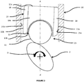
Figure 3 is a schematic cross-sectional partial view of a shoe and shoe guide for a drivetrain assembly of a high pressure fuel pump according to an embodiment of the invention in use during a pumping stroke; and -
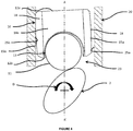
Figure 4 is a schematic cross-sectional partial view of the shoe and shoe guide for the drivetrain assembly ofFigure 3 during a filling stroke. - An embodiment of the invention is shown in
Figures 3 and4 . A high pressure diesel fuel pump comprises a pumping assembly (not shown) comprising a plunger (not shown) extending from a pump head (not shown) along a pumping axis A-A'. Ashoe 10 is in contact with a lower end of the plunger and aroller 11 is mounted within acavity 13 of theshoe 10 for contact with acam 2. The pump also comprises ashoe guide 20 mounted within a guide chamber (not shown) of the housing substantially between thecam 2 and the plunger and adapted to receive theshoe 10 androller 11 within abore 23 thereof, wherein the plunger is arranged for reciprocating linear movement along the pumping axis A-A' within a pumping chamber (not shown) of the housing. Oneside face shoe 10 comprises a convex curve thereon. - The
shoe 10 comprises anupper face 12a and alower face 12b. Thecavity 13 for theroller 11 is provided in thelower face 12b, whilst a plunger contact surface is provided by theupper face 12a. Between theupper face 12a and thelower face 12b are a pair of opposing end faces 14a and 14b (only one shown) and a pair of opposing side faces comprising a leadingface 15a and a trailingface 15b. Thecavity 13 for theroller 11 extends between the pair of end faces 14a and is open to both end faces 14a. The leadingface 15a and the trailingface 15b are closed to thecavity 13. - The
shoe 10 is generally cuboidal, with the leadingface 15a and the trailingface 15b being elongate compared with the end faces 14a. At the junction between the leadingface 15a and the trailingface 15b with the respective end faces 14a, theshoe 10 comprises bluntedcorners 18. Theshoe 10 is sized for a sliding fit with thebore 23 of theshoe guide 20 between two pairs of retaining walls, comprising end retaining walls (not shown) andside retaining walls cavity 13 comprises a half-cylindrical open-ended aperture sized to accommodate therotating roller 11. - In the embodiment shown, both the leading
face 15a and the trailingface 15b comprise a convex curve. The curve extends substantially from theupper face 12a of theshoe 10 to thelower face 12b of theshoe 10. The curve also extends substantially across the whole of the respective leadingface 15b and trailingface 15b between the two end faces 14a, 14b of theshoe 10 and as such covers substantially the whole of the respective leadingface 15a and the trailingface 15b. However, it is to be appreciated that to have an advantageous effect, the curve may either: only extend from theupper face 12a of theshoe 10 to part way down the respective leadingface 15a or the trailingface 15b, and as such may cover from at least 50% of a depth of the respective leadingface 15a or the trailingface 15b; and/or only extend from the across a portion of the respective leadingface 15a or the trailingface 15b of theshoe 10 between the two end faces 14a, 14b, and as such may cover from at least 50% of a length of the respective leadingface 15a or the trailingface 15b. - The curve on the leading
face 15a and the trailingface 15b comprise a uniform curve-profile. The curve profile comprises a curve with a radius of approximately 200 mm thereacross. However, it is to be appreciated that the curve profile may be non-uniform and could, for example comprise a gradually shallowing curve across the depth and/or the length of the respective leadingface 15a or the trailingface 15b. - The curve profile of both the leading
face 15a and the trailingface 15b are substantially the same in order to maintain balance to theshoe 10. - Since a 'leading' face is characterised by the direction D of rotation of the
cam 2, as the side face of theshoe 10 that is biased towards a corresponding internal wall of the bore 25 of theshoe guide 20 during the pumping stroke, but biased away from that internal wall during the filling stroke, in the Figures, the leading face has been designated as side face 15a and the leading internal wall as 25a where the direction D is clockwise. However, it is to be appreciated that either of said side faces 15a, 15b may be configured to comprise the leading face of theshoe 10 and either of saidwalls guide 20 may comprise the corresponding leading internal wall, with the remaining opposingside face internal wall cam 2 was reversed,side face 15b would be the leading face andinternal wall 25b would be the leading internal wall. - During assembly, the
shoe 10 is disposed in thebore 23 of theshoe guide 20 such that the end faces 14a of theshoe 10 contact the internal end walls and the leadingface 15a and the trailingface 15b contact the internal leadingwall 25a and the internal trailingwall 25b respectively. Thecavity 13 for theroller 11 is orientated downwardly towards thecam 2. Therefore, the convex curve of each of the leadingface 15a and the trailingface 15b span substantially across an entire width of the internal leadingwall 25a and the internal trailingwall 25b respectively. - In the described embodiment, both side faces 15a, 15b incorporate such a convex curve since both side faces 15a, 15b are prone to cavitation during the process pumping and filling stroke respectively. However, since greater cavitation is generally observed in the prior art on the leading face, in this
case 15a, and respective inside wall, in thiscase 25a, it also means that eitherside face shoe 10 can be used in either of two orientations and still function as intended, which minimises assembly issues. It is to be appreciated therefore, that only one of said side faces 15a, 15b may be provided with the convex curve to be orientated as the leading face during assembly. - In use, as the
cam 2 rotates in direction D to push theshoe 10 up to top dead centre (TDC), as shown inFigure 3 , the leadingface 15a is tilted to lean towardsinside wall 25a. The curve on the leadingface 15a prevents theshoe 10 from running on the top edge of the leadingface 15a. The curve on the leadingface 15a minimises the space between itself and theinside wall 25a caused by the tilt. Furthermore, the curve on the opposite trailingface 15b minimises the space created between itself and theinside wall 25b. Where spaces are reduced, cavitation is reduced. - In contrast, as the
cam 2 continues to rotate in direction D to drop theshoe 10 from TDC toward bottom dead centre (BDC), as shown inFigure 4 , instead the trailingface 15b is tilted to lean towardsinside wall 25b. The curve on the trailingface 15b prevents theshoe 10 from running on the top edge of the trailingface 15b. The curve on the trailingface 15b minimises the space between itself and theinside wall 25b caused by the tilt. Furthermore, the curve on the opposite leadingface 15a minimises the space created between itself and theinside wall 25a. - By 'high pressure fuel pump', it is intended to mean a pump operating at 2000 bars and above which is typically the case for a diesel pump but, despite this, the invention can be utilized for another type of pump such as a gasoline pump.
- Although a few preferred embodiments have been shown and described, it will be appreciated by those skilled in the art that various changes and modifications might be made without departing from the scope of the invention, as defined in the appended claims.
Claims (10)
- A high pressure fuel pump adapted to be actuated by a rotating cam (2), the pump having a pump head wherein a plunger is arranged for reciprocating linear movement along the pumping axis (A-A') within a pumping chamber; the pump being further provided with a shoe (2) guided in a shoe guide (20), said shoe (2) having an upper face (12a) cooperating with the plunger, an opposed lower face (12b) shaped to receiving a roller (11) for contact with the cam (2) and, between said upper and lower faces (12a, 12b), a side leading face (15a) sliding along a side internal leading wall (25a) of said guide (20) and, an opposed side trailing face (15b) sliding along a side internal trailing wall (25b) of said guide (20), characterised in that
at least one of said side leading or trailing face (15a, 15b) of the shoe (2) comprises a convex curve thereon. - The pump according to claim 1, wherein both the leading face (15a) of the shoe (20) and the trailing face (15b) of the shoe (10) comprise a convex curve thereon.
- The pump according to claim 2, wherein the leading face (15a) and of the trailing face (15b) are symmetrical, the convex curves matching together.
- The pump according to any one of claims 1 to 3, wherein the convex curve extends across at least a part of the respective side face (15a, 15b) between a top edge of said side face (15a, 15b) with said upper face (12a) to, a bottom edge of said side face (15a, 15b) with said lower face (12b).
- The pump according to claim 4, wherein the convex curve extends from the top edge of the respective side face (15a, 15b).
- The pump according to any one of claims 4 or 5, wherein the convex curve extends across the whole of the respective side face (15a, 15b) from the top edge to the bottom edge thereof.
- The pump according to any one of claims 1 to 6, wherein the convex curve comprises a consistent curve profile across the respective side leading or trailing face (15a, 15b).
- The pump according to any one of claims 1 to 7, wherein the convex curve comprises a radius of between 100 mm and 400 mm and preferably of approximately 200 mm.
- The pump according to any one of claims 1 to 8, wherein the pump is a diesel pump.
- A shoe (10) adapted to be arranged in a high pressure fuel pump as claimed in any one of the preceding claims.
Applications Claiming Priority (1)
| Application Number | Priority Date | Filing Date | Title |
|---|---|---|---|
| GB1606297.8A GB2549303A (en) | 2016-04-12 | 2016-04-12 | High pressure fuel pump |
Publications (1)
| Publication Number | Publication Date |
|---|---|
| EP3232047A1 true EP3232047A1 (en) | 2017-10-18 |
Family
ID=58501330
Family Applications (1)
| Application Number | Title | Priority Date | Filing Date |
|---|---|---|---|
| EP17165362.9A Withdrawn EP3232047A1 (en) | 2016-04-12 | 2017-04-06 | High pressure fuel pump |
Country Status (2)
| Country | Link |
|---|---|
| EP (1) | EP3232047A1 (en) |
| GB (1) | GB2549303A (en) |
Citations (4)
| Publication number | Priority date | Publication date | Assignee | Title |
|---|---|---|---|---|
| DE102006052484A1 (en) * | 2006-11-07 | 2008-05-08 | Robert Bosch Gmbh | Camshaft drive with a geometric roller stabilization |
| US20080295807A1 (en) * | 2006-02-20 | 2008-12-04 | Peter Bauer | High Pressure Pump, in Particular for a Fuel Injection System Of an Internal Combustion Engine |
| WO2011018389A1 (en) * | 2009-08-10 | 2011-02-17 | Robert Bosch Gmbh | High pressure pump |
| WO2015036440A1 (en) * | 2013-09-12 | 2015-03-19 | Continental Automotive Gmbh | Roller tappet |
Family Cites Families (1)
| Publication number | Priority date | Publication date | Assignee | Title |
|---|---|---|---|---|
| SU1763700A1 (en) * | 1990-10-31 | 1992-09-23 | Павлодарский Индустриальный Институт | Plunger of fuel pump |
-
2016
- 2016-04-12 GB GB1606297.8A patent/GB2549303A/en not_active Withdrawn
-
2017
- 2017-04-06 EP EP17165362.9A patent/EP3232047A1/en not_active Withdrawn
Patent Citations (4)
| Publication number | Priority date | Publication date | Assignee | Title |
|---|---|---|---|---|
| US20080295807A1 (en) * | 2006-02-20 | 2008-12-04 | Peter Bauer | High Pressure Pump, in Particular for a Fuel Injection System Of an Internal Combustion Engine |
| DE102006052484A1 (en) * | 2006-11-07 | 2008-05-08 | Robert Bosch Gmbh | Camshaft drive with a geometric roller stabilization |
| WO2011018389A1 (en) * | 2009-08-10 | 2011-02-17 | Robert Bosch Gmbh | High pressure pump |
| WO2015036440A1 (en) * | 2013-09-12 | 2015-03-19 | Continental Automotive Gmbh | Roller tappet |
Also Published As
| Publication number | Publication date |
|---|---|
| GB2549303A (en) | 2017-10-18 |
Similar Documents
| Publication | Publication Date | Title |
|---|---|---|
| KR101967505B1 (en) | Swash-plate hydraulic motor or swash-plate hydraulic pump | |
| US10174731B2 (en) | High pressure pump for a fuel injection system of an internal combustion engine | |
| EP3232047A1 (en) | High pressure fuel pump | |
| US10393118B2 (en) | Screw machine | |
| JP6299949B2 (en) | Piston for internal combustion engine | |
| CN106062354A (en) | Fuel pump | |
| EP2660458B1 (en) | High-pressure pump | |
| US11274626B2 (en) | Bore portion for receiving a reciprocating piston | |
| CN203926356U (en) | Bent axle | |
| CN110873037B (en) | Compressor and apparatus using the same | |
| US10808665B2 (en) | Camshaft for a pump, in particular a high pressure fuel pump, and pump having a camshaft | |
| EP2910769A1 (en) | Fuel pumping mechanism | |
| JP5885992B2 (en) | Lifter structure | |
| US20090047146A1 (en) | Eccentric Radial Piston Pump and Eccentric Radial Piston Motor | |
| JP2017501339A (en) | Fuel high pressure pump and pressure control device | |
| EP3139029B1 (en) | High pressure fuel pump | |
| EP3337975A1 (en) | High pressure diesel fuel pumps | |
| JP7610437B2 (en) | engine | |
| KR101419811B1 (en) | Pressurizing member for reciprocating pump | |
| KR102615466B1 (en) | Pumping assembly | |
| CN107429612B (en) | Internal combustion engine | |
| JP6139570B2 (en) | Cylinder block for a compressor, in particular a swash plate compressor, and a swash plate compressor | |
| KR102237730B1 (en) | compressor shoe | |
| KR101892068B1 (en) | Cylinder device having a function of preventing rotation of a rod | |
| JP2021092196A (en) | Pump lifter |
Legal Events
| Date | Code | Title | Description |
|---|---|---|---|
| PUAI | Public reference made under article 153(3) epc to a published international application that has entered the european phase |
Free format text: ORIGINAL CODE: 0009012 |
|
| STAA | Information on the status of an ep patent application or granted ep patent |
Free format text: STATUS: THE APPLICATION HAS BEEN PUBLISHED |
|
| AK | Designated contracting states |
Kind code of ref document: A1 Designated state(s): AL AT BE BG CH CY CZ DE DK EE ES FI FR GB GR HR HU IE IS IT LI LT LU LV MC MK MT NL NO PL PT RO RS SE SI SK SM TR |
|
| AX | Request for extension of the european patent |
Extension state: BA ME |
|
| STAA | Information on the status of an ep patent application or granted ep patent |
Free format text: STATUS: REQUEST FOR EXAMINATION WAS MADE |
|
| 17P | Request for examination filed |
Effective date: 20180418 |
|
| RBV | Designated contracting states (corrected) |
Designated state(s): AL AT BE BG CH CY CZ DE DK EE ES FI FR GB GR HR HU IE IS IT LI LT LU LV MC MK MT NL NO PL PT RO RS SE SI SK SM TR |
|
| STAA | Information on the status of an ep patent application or granted ep patent |
Free format text: STATUS: EXAMINATION IS IN PROGRESS |
|
| 17Q | First examination report despatched |
Effective date: 20181128 |
|
| RAP1 | Party data changed (applicant data changed or rights of an application transferred) |
Owner name: DELPHI TECHNOLOGIES IP LIMITED |
|
| STAA | Information on the status of an ep patent application or granted ep patent |
Free format text: STATUS: THE APPLICATION IS DEEMED TO BE WITHDRAWN |
|
| 18D | Application deemed to be withdrawn |
Effective date: 20210120 |