EP3232019A1 - Heat shield with axial retention lock - Google Patents
Heat shield with axial retention lock Download PDFInfo
- Publication number
- EP3232019A1 EP3232019A1 EP17166212.5A EP17166212A EP3232019A1 EP 3232019 A1 EP3232019 A1 EP 3232019A1 EP 17166212 A EP17166212 A EP 17166212A EP 3232019 A1 EP3232019 A1 EP 3232019A1
- Authority
- EP
- European Patent Office
- Prior art keywords
- heat shield
- combustor
- diffuser case
- tab
- support lock
- Prior art date
- Legal status (The legal status is an assumption and is not a legal conclusion. Google has not performed a legal analysis and makes no representation as to the accuracy of the status listed.)
- Granted
Links
Images



Classifications
-
- F—MECHANICAL ENGINEERING; LIGHTING; HEATING; WEAPONS; BLASTING
- F01—MACHINES OR ENGINES IN GENERAL; ENGINE PLANTS IN GENERAL; STEAM ENGINES
- F01D—NON-POSITIVE DISPLACEMENT MACHINES OR ENGINES, e.g. STEAM TURBINES
- F01D9/00—Stators
- F01D9/02—Nozzles; Nozzle boxes; Stator blades; Guide conduits, e.g. individual nozzles
- F01D9/023—Transition ducts between combustor cans and first stage of the turbine in gas-turbine engines; their cooling or sealings
-
- F—MECHANICAL ENGINEERING; LIGHTING; HEATING; WEAPONS; BLASTING
- F23—COMBUSTION APPARATUS; COMBUSTION PROCESSES
- F23R—GENERATING COMBUSTION PRODUCTS OF HIGH PRESSURE OR HIGH VELOCITY, e.g. GAS-TURBINE COMBUSTION CHAMBERS
- F23R3/00—Continuous combustion chambers using liquid or gaseous fuel
- F23R3/02—Continuous combustion chambers using liquid or gaseous fuel characterised by the air-flow or gas-flow configuration
- F23R3/04—Air inlet arrangements
- F23R3/10—Air inlet arrangements for primary air
-
- F—MECHANICAL ENGINEERING; LIGHTING; HEATING; WEAPONS; BLASTING
- F01—MACHINES OR ENGINES IN GENERAL; ENGINE PLANTS IN GENERAL; STEAM ENGINES
- F01D—NON-POSITIVE DISPLACEMENT MACHINES OR ENGINES, e.g. STEAM TURBINES
- F01D25/00—Component parts, details, or accessories, not provided for in, or of interest apart from, other groups
- F01D25/08—Cooling; Heating; Heat-insulation
- F01D25/14—Casings modified therefor
- F01D25/145—Thermally insulated casings
-
- F—MECHANICAL ENGINEERING; LIGHTING; HEATING; WEAPONS; BLASTING
- F01—MACHINES OR ENGINES IN GENERAL; ENGINE PLANTS IN GENERAL; STEAM ENGINES
- F01D—NON-POSITIVE DISPLACEMENT MACHINES OR ENGINES, e.g. STEAM TURBINES
- F01D25/00—Component parts, details, or accessories, not provided for in, or of interest apart from, other groups
- F01D25/24—Casings; Casing parts, e.g. diaphragms, casing fastenings
- F01D25/243—Flange connections; Bolting arrangements
-
- F—MECHANICAL ENGINEERING; LIGHTING; HEATING; WEAPONS; BLASTING
- F01—MACHINES OR ENGINES IN GENERAL; ENGINE PLANTS IN GENERAL; STEAM ENGINES
- F01D—NON-POSITIVE DISPLACEMENT MACHINES OR ENGINES, e.g. STEAM TURBINES
- F01D25/00—Component parts, details, or accessories, not provided for in, or of interest apart from, other groups
- F01D25/24—Casings; Casing parts, e.g. diaphragms, casing fastenings
- F01D25/246—Fastening of diaphragms or stator-rings
-
- F—MECHANICAL ENGINEERING; LIGHTING; HEATING; WEAPONS; BLASTING
- F23—COMBUSTION APPARATUS; COMBUSTION PROCESSES
- F23R—GENERATING COMBUSTION PRODUCTS OF HIGH PRESSURE OR HIGH VELOCITY, e.g. GAS-TURBINE COMBUSTION CHAMBERS
- F23R3/00—Continuous combustion chambers using liquid or gaseous fuel
- F23R3/42—Continuous combustion chambers using liquid or gaseous fuel characterised by the arrangement or form of the flame tubes or combustion chambers
- F23R3/60—Support structures; Attaching or mounting means
-
- F—MECHANICAL ENGINEERING; LIGHTING; HEATING; WEAPONS; BLASTING
- F05—INDEXING SCHEMES RELATING TO ENGINES OR PUMPS IN VARIOUS SUBCLASSES OF CLASSES F01-F04
- F05D—INDEXING SCHEME FOR ASPECTS RELATING TO NON-POSITIVE-DISPLACEMENT MACHINES OR ENGINES, GAS-TURBINES OR JET-PROPULSION PLANTS
- F05D2230/00—Manufacture
- F05D2230/60—Assembly methods
- F05D2230/64—Assembly methods using positioning or alignment devices for aligning or centring, e.g. pins
- F05D2230/642—Assembly methods using positioning or alignment devices for aligning or centring, e.g. pins using maintaining alignment while permitting differential dilatation
-
- F—MECHANICAL ENGINEERING; LIGHTING; HEATING; WEAPONS; BLASTING
- F05—INDEXING SCHEMES RELATING TO ENGINES OR PUMPS IN VARIOUS SUBCLASSES OF CLASSES F01-F04
- F05D—INDEXING SCHEME FOR ASPECTS RELATING TO NON-POSITIVE-DISPLACEMENT MACHINES OR ENGINES, GAS-TURBINES OR JET-PROPULSION PLANTS
- F05D2240/00—Components
- F05D2240/10—Stators
- F05D2240/15—Heat shield
-
- F—MECHANICAL ENGINEERING; LIGHTING; HEATING; WEAPONS; BLASTING
- F05—INDEXING SCHEMES RELATING TO ENGINES OR PUMPS IN VARIOUS SUBCLASSES OF CLASSES F01-F04
- F05D—INDEXING SCHEME FOR ASPECTS RELATING TO NON-POSITIVE-DISPLACEMENT MACHINES OR ENGINES, GAS-TURBINES OR JET-PROPULSION PLANTS
- F05D2260/00—Function
- F05D2260/20—Heat transfer, e.g. cooling
- F05D2260/231—Preventing heat transfer
-
- F—MECHANICAL ENGINEERING; LIGHTING; HEATING; WEAPONS; BLASTING
- F05—INDEXING SCHEMES RELATING TO ENGINES OR PUMPS IN VARIOUS SUBCLASSES OF CLASSES F01-F04
- F05D—INDEXING SCHEME FOR ASPECTS RELATING TO NON-POSITIVE-DISPLACEMENT MACHINES OR ENGINES, GAS-TURBINES OR JET-PROPULSION PLANTS
- F05D2260/00—Function
- F05D2260/30—Retaining components in desired mutual position
- F05D2260/31—Retaining bolts or nuts
-
- F—MECHANICAL ENGINEERING; LIGHTING; HEATING; WEAPONS; BLASTING
- F23—COMBUSTION APPARATUS; COMBUSTION PROCESSES
- F23R—GENERATING COMBUSTION PRODUCTS OF HIGH PRESSURE OR HIGH VELOCITY, e.g. GAS-TURBINE COMBUSTION CHAMBERS
- F23R2900/00—Special features of, or arrangements for continuous combustion chambers; Combustion processes therefor
- F23R2900/00012—Details of sealing devices
-
- Y—GENERAL TAGGING OF NEW TECHNOLOGICAL DEVELOPMENTS; GENERAL TAGGING OF CROSS-SECTIONAL TECHNOLOGIES SPANNING OVER SEVERAL SECTIONS OF THE IPC; TECHNICAL SUBJECTS COVERED BY FORMER USPC CROSS-REFERENCE ART COLLECTIONS [XRACs] AND DIGESTS
- Y02—TECHNOLOGIES OR APPLICATIONS FOR MITIGATION OR ADAPTATION AGAINST CLIMATE CHANGE
- Y02T—CLIMATE CHANGE MITIGATION TECHNOLOGIES RELATED TO TRANSPORTATION
- Y02T50/00—Aeronautics or air transport
- Y02T50/60—Efficient propulsion technologies, e.g. for aircraft
Definitions
- a gas turbine engine typically includes a fan section, a compressor section, a combustor section, and a turbine section.
- air is pressurized in the compressor section and is mixed with fuel and burned in the combustor section to generate hot combustion gases.
- the hot combustion gases flow through the turbine section, which extracts energy from the hot combustion gases to power the compressor section and other gas turbine engine loads.
- the compressor section typically includes low pressure and high pressure compressors, and the turbine section includes low pressure and high pressure turbines.
- the combustor is typically coupled to an engine case of the gas turbine engine.
- the engine case may include a diffuser case, which circumscribes the compressor section.
- the diffuser case and fittings may be subjected to relatively high temperatures due to heat convectively transferred from the combustor to the diffuser case.
- Thermal loads in the diffuser case may cause thermal gradients that may stress, deform, fracture, and/or degrade portions of the diffuser case over time.
- a flange of the diffuser case may experience thermal gradients of 500°F (260°C) to 600°F (315°C). The thermal gradients cause stress that may shorten the operational life of engine case components.
- the thermal load on an engine case may increase the overall length of the engine case. This thermal growth may contribute to misalignment of engine components.
- the heat shield assembly may include a heat shield and a support lock.
- the heat shield may have an annular shape.
- the heat shield may define an aperture extending through the heat shield.
- the support lock may have a tab extending radially outward from a distal surface of the support lock.
- the aperture in the heat shield may be configured to retain the tab of the support lock.
- a distal surface of the support lock may be configured to be coupled to the inner surface of the heat shield.
- the aperture may be disposed in proximity to an aft end of the heat shield.
- the tab may be disposed at a forward end of the support lock.
- the outer surface of the heat shield may form a seal with the engine case.
- the outer surface of the heat shield and an inner surface of the engine case may define a gap.
- the engine case may be a diffuser case.
- a combustor section of a gas turbine engine is also provided.
- the combustor section may include a combustor and a diffuser case disposed about the combustor.
- a heat shield may have an annular shape and may be disposed between the combustor and the diffuser case. The heat shield may define an aperture extending through the heat shield.
- the heat shield may be configured to couple to the diffuser case.
- the heat shield may be disposed circumferentially along an inner surface of the diffuser case.
- An outer surface of the heat shield may form a seal with the inner surface of the diffuser case.
- the outer surface of the heat shield and the inner surface of the diffuser case may define a gap.
- a support lock may have a tab extending radially outward from a distal surface of the support lock.
- the aperture in the heat shield may be configured to retain the tab of the support lock.
- the tab may be disposed at a forward end of the support lock.
- the tab and the aperture may be configured to retain the heat shield in an axial direction.
- the gas turbine engine may include a combustor section as defined in any of the preceding paragraphs.
- the gas turbine engine may comprise a combustor and a diffuser case disposed about the combustor.
- a heat shield assembly may be disposed between the combustor and diffuser case.
- the heat shield assembly may include a heat shield having an annular shape.
- the heat shield may define an aperture extending through the heat shield.
- the heat shield assembly may further include a support lock having a tab extending radially outward from a distal surface of the support lock.
- the aperture in the heat shield may be configured to retain the tab of the support lock.
- turbine section 28 receives combusted gas or exhaust from combustor section 26.
- turbine section 28 may include multiple rows of vanes and multiple rows of blades that can rotate about an axis with respect to the vanes. Combusted gas from the combustor section 26 is channeled to the turbine section where it can be directed through the turbine vanes and blades.
- high pressure turbine 54 may include a plurality of vanes, such as vane 112, and a plurality of blades. Vane 112 may operate as a first stage high pressure turbine vane of high pressure turbine 54.
- Vane 112 and combustor 56 may attach to outer diffuser case 70 by a combustor vane support 114.
- Combustor 56 may be further secured to outer diffuser case 70 and combustor vane support 114 by a plurality of support locks 116.
- diffuser mount assembly 100 includes a plurality of support locks 116 disposed at regular intervals circumferentially around combustor 56.
- Each support lock 116 and combustor vane support 114 may be configured to receive a fastener 118.
- a fastener 118 may be passed through combustor vane support 114 and support lock 116 to mechanically couple support lock 116 to combustor vane support 114.
- outer diffuser case 70 may be attached to HPT case 72.
- Outer diffuser case 70 may include a diffuser case flange 120 extending radially from outer diffuser case 70 at or near the aft end of outer diffuser case 70.
- HPT case 72 may include an HPT case flange 122 extending radially from HPT case 72 at or near the forward end of HPT case 72.
- Diffuser case flange 120 and HPT case flange 122 may mate together at attachment interface 74.
- Flanges 120, 122 may be in directly abutting engagement with each other at attachment interface 74 and may be secured by a plurality of fasteners 124.
- Fasteners 124 may be passed through flanges 120, 122 to mechanically couple outer diffuser case 70 and HPT case 72.
- Fasteners 124 may include rivets, bolts, or other suitable fasteners to couple outer diffuser case 70 and HPT case 72 along flanges 120, 122.
- Heat radiating from combustor 56 may introduce thermal loads on outer diffuser case 70 and diffuser case flange 120.
- heat may convectively transfer from combustor 56 to outer diffuser case 70 and to diffuser case flange 120, resulting in a thermal gradient in diffuser case flange 120.
- a heat shield 126 may be configured to block heat radiating from combustor 56 from directly impinging on outer diffuser case 70 and on diffuser case flange 120.
- Heat shield 126 may be disposed between combustor 56 and outer diffuser case 70.
- a heat shield 126 may extend circumferentially along an inner wall of outer diffuser case 70. Heat shield 126 may help reduce the thermal gradients in diffuser mount flange 120, thereby reducing stress on diffuser case flange 120.
- Heat shield 126 may be used to insulate outer diffuser case 70 and diffuser case flange 120 from convective heat transfer from combustor 56 through gas flowing through outer plenum 110.
- a forward end 130 of heat shield 126 may contact outer diffuser case 70 at a contact surface 132.
- An aft end 134 of heat shield 126 may further contact outer diffuser case 70 at a contact surface 136.
- Heat shield 126 may form a seal with outer diffuser case 70 at contact surface 132 and contact surface 136.
- Contact surfaces 132, 136 may each form an annular seal disposed circumferentially along an inner surface 140 of outer diffuser case 70.
- a portion of heat shield 126 may be configured to be separated from outer diffuser case 70 by a gap 144.
- an outer surface 142 of heat shield 126 and an inner surface 140 of outer diffuser case 70 define gap 144, which is disposed between heat shield 126 and outer diffuser case 70.
- Gap 144 may extend axially and circumferentially along heat shield 126 between contact surfaces 132, 136.
- Gap 144 may be configured such that a conductive thermal path does not exist between heat shield 126 and outer diffuser case 70 at gap 144.
- Gap 144 may be configured to minimize convective heat transfer between heat shield 126 and outer diffuser case 70. Accordingly, heat shield 126 may be configured to minimize convective heat transfer between combustor 56 and outer diffuser case 70, thereby decreasing the temperature of diffuser case flange 120. The reduced temperature of diffuser case flange 120 reduces thermal gradients and stress experienced by diffuser case flange 120 and increases the operational life of diffuser case flange 120.
- Core airflow C generally flows through combustor section 26 in the direction of arrows 146.
- core airflow C may backflow or may travel in a direction other than in the direction of arrows 146.
- Backflow of core airflow C can disrupt the position of engine components and may lead to liberation of heat shield 126 (e.g., heat shield 126 may loosen or detach from outer diffuser case 70), increasing the risk of damage to the surrounding engine structure.
- Thermal growth of engine components, such as the engine case may also lead to liberation of heat shield 126.
- An axial retention feature 150 may be included to prevent axial liberation of heat shield 126, due to thermal growth and/or during a surge event.
- axial retention feature 150 may include a plurality of apertures 152 formed in heat shield 126.
- Apertures 152 may be configured as openings formed completely through heat shield 126, wherein apertures 152 may extend from outer surface 142 to an inner surface 154 of heat shield 126. Inner sidewalls of heat shield 126 may define apertures 152.
- tab 156 coupled to outer diffuser case 70 and to aperture 152 of heat shield 126 may prevent heat shield 126 from moving axially in the z direction, for example, with respect to outer diffuser case 70.
- axial retention feature 150 may retain heat shield 126 in the axial direction or reduce movement of heat shield 126 in the axial direction, or z direction.
- Tab 156 extending completely through heat shield 126 may provide improved axial retention during thermal growth or a surge event.
- heat shield 126 may be circumferentially continuous (e.g., annular or ring shaped). Heat shield 126 having annular geometry may interface with and fit within outer diffuser case 70, which may also have annular geometry. Heat shield 126 includes an outer surface 142 and an inner surface 154. In various embodiments, heat shield 126 may include a plurality of apertures 152 disposed at regular intervals around the circumference of heat shield 126. Apertures 152 may be configured to align with support locks 116. A number of apertures 152 may correspond to the number of support locks 116. Apertures 152 may be formed in proximity to aft end 134 of heat shield 126.
- a forward side surface of tab 156 may be coplanar or continuous with a forward surface 170 of support lock 116.
- Tab 156 may operate as a first axial retention feature of support lock 116 and may be configured to complement and interface with a second axial retention feature, such as aperture 152, of heat shield 126. While the first axial retention feature, or tab 156, of support lock 116 is depicted as rectangular in shape, it is to be understood that any shape complementary to the second axial retention feature, or aperture 152, of heat shield 126 may be used.
- heat shield 126 may be integral to (e.g., forged or manufactured as part of) support lock 116. Apertures 152 and tab 156 may be disposed in proximity to aft end 134 of heat shield 126. Tab 156 may be disposed at a forward end of support lock 116. A position of tab 156 and apertures 152 is configured to provide both axial retention and thermal shielding. A configuration with tab 156 extending through heat shield 126 may improve axial retention. A configuration with tab 156 disposed at a forward end of support lock 116 may improve thermal shielding by reducing heat transfer from support lock 116 and tab 156 to outer diffuser case 70.
Landscapes
- Engineering & Computer Science (AREA)
- Mechanical Engineering (AREA)
- General Engineering & Computer Science (AREA)
- Chemical & Material Sciences (AREA)
- Combustion & Propulsion (AREA)
- Turbine Rotor Nozzle Sealing (AREA)
Abstract
Description
- The present disclosure relates to gas turbine engines, and, more specifically, to a combustor section and engine case.
- A gas turbine engine typically includes a fan section, a compressor section, a combustor section, and a turbine section. In general, during operation, air is pressurized in the compressor section and is mixed with fuel and burned in the combustor section to generate hot combustion gases. The hot combustion gases flow through the turbine section, which extracts energy from the hot combustion gases to power the compressor section and other gas turbine engine loads. The compressor section typically includes low pressure and high pressure compressors, and the turbine section includes low pressure and high pressure turbines.
- The combustor is typically coupled to an engine case of the gas turbine engine. The engine case may include a diffuser case, which circumscribes the compressor section. The diffuser case and fittings may be subjected to relatively high temperatures due to heat convectively transferred from the combustor to the diffuser case. Thermal loads in the diffuser case may cause thermal gradients that may stress, deform, fracture, and/or degrade portions of the diffuser case over time. A flange of the diffuser case may experience thermal gradients of 500°F (260°C) to 600°F (315°C). The thermal gradients cause stress that may shorten the operational life of engine case components. During operation, the thermal load on an engine case may increase the overall length of the engine case. This thermal growth may contribute to misalignment of engine components.
- A heat shield assembly for an engine case of a gas turbine engine is described herein, in accordance with various embodiments. The heat shield assembly may include a heat shield and a support lock. The heat shield may have an annular shape. The heat shield may define an aperture extending through the heat shield. The support lock may have a tab extending radially outward from a distal surface of the support lock. The aperture in the heat shield may be configured to retain the tab of the support lock.
- In various embodiments, a distal surface of the support lock may be configured to be coupled to the inner surface of the heat shield. The aperture may be disposed in proximity to an aft end of the heat shield. The tab may be disposed at a forward end of the support lock. The outer surface of the heat shield may form a seal with the engine case. The outer surface of the heat shield and an inner surface of the engine case may define a gap. In various embodiments, the engine case may be a diffuser case.
- A combustor section of a gas turbine engine is also provided. The combustor section may include a combustor and a diffuser case disposed about the combustor. A heat shield may have an annular shape and may be disposed between the combustor and the diffuser case. The heat shield may define an aperture extending through the heat shield.
- In various embodiments, the heat shield may be configured to couple to the diffuser case. The heat shield may be disposed circumferentially along an inner surface of the diffuser case. An outer surface of the heat shield may form a seal with the inner surface of the diffuser case. The outer surface of the heat shield and the inner surface of the diffuser case may define a gap. A support lock may have a tab extending radially outward from a distal surface of the support lock. The aperture in the heat shield may be configured to retain the tab of the support lock. The tab may be disposed at a forward end of the support lock. The tab and the aperture may be configured to retain the heat shield in an axial direction.
- A gas turbine engine is also provided. The gas turbine engine may include a combustor section as defined in any of the preceding paragraphs. For example the gas turbine engine may comprise a combustor and a diffuser case disposed about the combustor. A heat shield assembly may be disposed between the combustor and diffuser case. The heat shield assembly may include a heat shield having an annular shape. The heat shield may define an aperture extending through the heat shield. The heat shield assembly may further include a support lock having a tab extending radially outward from a distal surface of the support lock. The aperture in the heat shield may be configured to retain the tab of the support lock.
- In various embodiments, the heat shield may be disposed circumferentially along an inner surface of the diffuser case. An outer surface of the heat shield may form a seal with the inner surface of the diffuser case. The outer surface of the heat shield and the inner surface of the diffuser case may define a gap.
- The foregoing features and elements may be combined in various combinations without exclusivity, unless expressly indicated otherwise. These features and elements as well as the operation thereof will become more apparent in light of the following description and the accompanying drawings. It should be understood, however, the following description and drawings are intended to be exemplary in nature and non-limiting.
- The subject matter of the present disclosure is particularly pointed out and distinctly claimed in the concluding portion of the specification. A more complete understanding of the present disclosure, however, may best be obtained by referring to the detailed description and claims when considered in connection with the figures, wherein like numerals denote like elements.
-
FIG. 1 illustrates a cross-sectional view of an exemplary gas turbine engine, in accordance with various embodiments; -
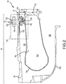
FIG. 2 illustrates a cross-sectional view of a combustor and a case of a gas turbine engine including a heat shield and an axial retention feature, in accordance with various embodiments; -
FIG. 3A illustrates a cross-sectional view of a diffuser case flange having a heat shield, in accordance with various embodiments; -
FIG. 3B illustrates a perspective view of a heat shield, in accordance with various embodiments; -
FIG. 3C illustrates a perspective view of a support lock having an axial retention feature, in accordance with various embodiments; and -
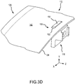
FIG. 3D illustrates a perspective view of a heat shield and support lock, in accordance with various embodiments. - All ranges and ratio limits disclosed herein may be combined. It is to be understood that unless specifically stated otherwise, references to "a," "an," and/or "the" may include one or more than one and that reference to an item in the singular may also include the item in the plural.
- The detailed description of various embodiments herein makes reference to the accompanying drawings, which show various embodiments by way of illustration. While these various embodiments are described in sufficient detail to enable those skilled in the art to practice the disclosure, it should be understood that other embodiments may be realized and that logical, chemical, and mechanical changes may be made without departing from the scope of the disclosure. Thus, the detailed description herein is presented for purposes of illustration only and not of limitation. For example, the steps recited in any of the method or process descriptions may be executed in any order and are not necessarily limited to the order presented. Furthermore, any reference to singular includes plural embodiments, and any reference to more than one component or step may include a singular embodiment or step. Also, any reference to attached, fixed, connected, or the like may include permanent, removable, temporary, partial, full, and/or any other possible attachment option. Additionally, any reference to without contact (or similar phrases) may also include reduced contact or minimal contact. Surface shading lines may be used throughout the figures to denote different parts but not necessarily to denote the same or different materials.
- As used herein, "aft" refers to the direction associated with the tail (e.g., the back end) of an aircraft, or generally, to the direction of exhaust of the gas turbine engine. As used herein, "forward" refers to the direction associated with the nose (e.g., the front end) of an aircraft, or generally, to the direction of flight or motion.
- As used herein, "distal" refers to the direction radially outward, or generally, away from the axis of rotation of a turbine engine. As used herein, "proximal" refers to a direction radially inward, or generally, towards the axis of rotation of a turbine engine.
- In various embodiments and with reference to
FIG. 1 , agas turbine engine 20 is provided.Gas turbine engine 20 may be a two-spool turbofan that generally incorporates afan section 22, acompressor section 24, acombustor section 26 and aturbine section 28. Alternative engines may include, for example, an augmentor section among other systems or features. In operation,fan section 22 can drive coolant (e.g., air) along a bypass flow-path B whilecompressor section 24 can drive coolant along a core flow-path C for compression and communication intocombustor section 26 then expansion throughturbine section 28. Although depicted as a turbofangas turbine engine 20 herein, it should be understood that the concepts described herein are not limited to use with turbofans as the teachings may be applied to other types of turbine engines including three-spool architectures. -
Gas turbine engine 20 may generally comprise alow speed spool 30 and ahigh speed spool 32 mounted for rotation about an engine central longitudinal axis A-A' relative to an enginestatic structure 36 or engine case viaseveral bearing systems 38, 38-1, and 38-2. Engine central longitudinal axis A-A' is oriented in the z direction on the provided xyz axis. It should be understood that various bearingsystems 38 at various locations may alternatively or additionally be provided, including for example, bearingsystem 38, bearing system 38-1, and bearing system 38-2. -
Low speed spool 30 may generally comprise aninner shaft 40 that interconnects afan 42, alow pressure compressor 44 and alow pressure turbine 46.Inner shaft 40 may be connected to fan 42 through a gearedarchitecture 48 that can drivefan 42 at a lower speed thanlow speed spool 30.Geared architecture 48 may comprise a gear assembly 60 enclosed within agear housing 62. Gear assembly 60 couplesinner shaft 40 to a rotating fan structure.High speed spool 32 may comprise anouter shaft 50 that interconnects ahigh pressure compressor 52 andhigh pressure turbine 54. Acombustor 56 may be located betweenhigh pressure compressor 52 andhigh pressure turbine 54. Anouter diffuser case 70 of enginestatic structure 36 may enclose thecombustor 56. A high pressure turbine (HPT)case 72 of enginestatic structure 36 may enclosehigh pressure turbine 54. An aft end ofouter diffuser case 70 may be attached to a forward end ofHPT case 72 at anattachment interface 74. Amid-turbine frame 57 of enginestatic structure 36 may be located generally betweenhigh pressure turbine 54 andlow pressure turbine 46.Mid-turbine frame 57 may support one ormore bearing systems 38 inturbine section 28.Inner shaft 40 andouter shaft 50 may be concentric and rotate via bearingsystems 38 about the engine central longitudinal axis A-A', which is collinear with their longitudinal axes. As used herein, a "high pressure" compressor or turbine experiences a higher pressure than a corresponding "low pressure" compressor or turbine. - The core airflow C may be compressed by
low pressure compressor 44 thenhigh pressure compressor 52, mixed and burned with fuel incombustor 56, then expanded overhigh pressure turbine 54 andlow pressure turbine 46.Turbines low speed spool 30 andhigh speed spool 32 in response to the expansion. -
Gas turbine engine 20 may be, for example, a high-bypass ratio geared aircraft engine. In various embodiments, the bypass ratio ofgas turbine engine 20 may be greater than about six. In various embodiments, the bypass ratio ofgas turbine engine 20 may be greater than ten. In various embodiments, gearedarchitecture 48 may be an epicyclic gear train, such as a star gear system (sun gear in meshing engagement with a plurality of star gears supported by a carrier and in meshing engagement with a ring gear) or other gear system.Geared architecture 48 may have a gear reduction ratio of greater than about 2.3 andlow pressure turbine 46 may have a pressure ratio that is greater than about five. In various embodiments, the bypass ratio ofgas turbine engine 20 is greater than about ten. In various embodiments, the diameter offan 42 may be significantly larger than that of thelow pressure compressor 44, and thelow pressure turbine 46 may have a pressure ratio that is greater than about five.Low pressure turbine 46 pressure ratio may be measured prior to inlet oflow pressure turbine 46 as related to the pressure at the outlet oflow pressure turbine 46 prior to an exhaust nozzle. It should be understood, however, that the above parameters are exemplary of various embodiments of a suitable geared architecture engine and that the present disclosure contemplates other gas turbine engines including direct drive turbofans. - With reference to
FIG. 2 , acombustor section 26 is shown, in accordance with various embodiments.Combustor section 26 generally includescombustor 56, which may be coupled toouter diffuser case 70 by adiffuser mount assembly 100.Combustor 56 generally includes acombustion chamber 102 defined by acombustor wall 104.Combustor 56 may be encased byouter diffuser case 70 having an annular geometry and disposed aboutcombustor 56.Combustor 56 may be further encased by aninner diffuser case 106.Inner diffuser case 106 is spaced radially inward fromcombustor wall 104 to define aninner plenum 108.Outer diffuser case 70 is spaced radially outward fromcombustor wall 104 to define anouter plenum 110. - Referring briefly to
FIG. 1 ,combustor 56 may be disposed downstream of thecompressor section 24 to receive compressed airflow therefrom. Referring now toFIG. 2 ,Combustion chamber 102 contains the combustion products that flow axially towardturbine section 28. Gas leavinghigh pressure compressor 52 may flow intocombustion chamber 102 to supplycombustor 56 with air for combustion. Uncombusted gas may be mixed with fuel and burned incombustion chamber 102. Combusted gas incombustor 56 may reach or exceed temperatures of up to 3,500°F (1,925°C) or higher. Heat may radiate fromcombustor 56 to other nearby components which may cause the nearby components to increase in temperature. - With momentary reference to
FIG. 1 ,turbine section 28 receives combusted gas or exhaust fromcombustor section 26. In various embodiments,turbine section 28 may include multiple rows of vanes and multiple rows of blades that can rotate about an axis with respect to the vanes. Combusted gas from thecombustor section 26 is channeled to the turbine section where it can be directed through the turbine vanes and blades. With reference toFIGS. 1 and2 ,high pressure turbine 54 may include a plurality of vanes, such asvane 112, and a plurality of blades.Vane 112 may operate as a first stage high pressure turbine vane ofhigh pressure turbine 54.Vane 112 andcombustor 56 may attach toouter diffuser case 70 by acombustor vane support 114.Combustor 56 may be further secured toouter diffuser case 70 andcombustor vane support 114 by a plurality of support locks 116. In various embodiments,diffuser mount assembly 100 includes a plurality ofsupport locks 116 disposed at regular intervals circumferentially aroundcombustor 56. Eachsupport lock 116 andcombustor vane support 114 may be configured to receive afastener 118. Afastener 118 may be passed throughcombustor vane support 114 andsupport lock 116 to mechanically couplesupport lock 116 tocombustor vane support 114. - In various embodiments,
outer diffuser case 70 may be attached toHPT case 72.Outer diffuser case 70 may include adiffuser case flange 120 extending radially fromouter diffuser case 70 at or near the aft end ofouter diffuser case 70.HPT case 72 may include anHPT case flange 122 extending radially fromHPT case 72 at or near the forward end ofHPT case 72.Diffuser case flange 120 andHPT case flange 122 may mate together atattachment interface 74.Flanges attachment interface 74 and may be secured by a plurality offasteners 124.Fasteners 124 may be passed throughflanges outer diffuser case 70 andHPT case 72.Fasteners 124 may include rivets, bolts, or other suitable fasteners to coupleouter diffuser case 70 andHPT case 72 alongflanges - Heat radiating from
combustor 56 may introduce thermal loads onouter diffuser case 70 anddiffuser case flange 120. For example, heat may convectively transfer fromcombustor 56 toouter diffuser case 70 and todiffuser case flange 120, resulting in a thermal gradient indiffuser case flange 120. Aheat shield 126 may be configured to block heat radiating fromcombustor 56 from directly impinging onouter diffuser case 70 and ondiffuser case flange 120.Heat shield 126 may be disposed betweencombustor 56 andouter diffuser case 70. In various embodiments, aheat shield 126 may extend circumferentially along an inner wall ofouter diffuser case 70.Heat shield 126 may help reduce the thermal gradients indiffuser mount flange 120, thereby reducing stress ondiffuser case flange 120. - With reference to
FIG. 3A , a cross-sectional view ofdiffuser mount assembly 100 is shown withheat shield 126, in accordance with various embodiments.Heat shield 126 may be used to insulateouter diffuser case 70 and diffuser case flange 120 from convective heat transfer fromcombustor 56 through gas flowing throughouter plenum 110. In various embodiments, aforward end 130 ofheat shield 126 may contactouter diffuser case 70 at acontact surface 132. Anaft end 134 ofheat shield 126 may further contactouter diffuser case 70 at acontact surface 136.Heat shield 126 may form a seal withouter diffuser case 70 atcontact surface 132 andcontact surface 136. Contact surfaces 132, 136 may each form an annular seal disposed circumferentially along aninner surface 140 ofouter diffuser case 70. A portion ofheat shield 126 may be configured to be separated fromouter diffuser case 70 by agap 144. In various embodiments, anouter surface 142 ofheat shield 126 and aninner surface 140 ofouter diffuser case 70 definegap 144, which is disposed betweenheat shield 126 andouter diffuser case 70.Gap 144 may extend axially and circumferentially alongheat shield 126 between contact surfaces 132, 136.Gap 144 may be configured such that a conductive thermal path does not exist betweenheat shield 126 andouter diffuser case 70 atgap 144.Gap 144 may be configured to minimize convective heat transfer betweenheat shield 126 andouter diffuser case 70. Accordingly,heat shield 126 may be configured to minimize convective heat transfer betweencombustor 56 andouter diffuser case 70, thereby decreasing the temperature ofdiffuser case flange 120. The reduced temperature ofdiffuser case flange 120 reduces thermal gradients and stress experienced bydiffuser case flange 120 and increases the operational life ofdiffuser case flange 120. - Core airflow C generally flows through
combustor section 26 in the direction ofarrows 146. During a surge event, core airflow C may backflow or may travel in a direction other than in the direction ofarrows 146. Backflow of core airflow C can disrupt the position of engine components and may lead to liberation of heat shield 126 (e.g.,heat shield 126 may loosen or detach from outer diffuser case 70), increasing the risk of damage to the surrounding engine structure. Thermal growth of engine components, such as the engine case, may also lead to liberation ofheat shield 126. Anaxial retention feature 150 may be included to prevent axial liberation ofheat shield 126, due to thermal growth and/or during a surge event. In various embodiments,axial retention feature 150 may include a plurality ofapertures 152 formed inheat shield 126.Apertures 152 may be configured as openings formed completely throughheat shield 126, whereinapertures 152 may extend fromouter surface 142 to aninner surface 154 ofheat shield 126. Inner sidewalls ofheat shield 126 may defineapertures 152. -
Axial retention feature 150 may further include atab 156 ofsupport lock 116. In various embodiments, each of the plurality ofapertures 152 may be configured to receive atab 156 ofsupport lock 116.Tab 156 disposed withinaperture 152 may form a tight fit such thatgap 144 remains sealed betweenouter surface 142 ofheat shield 126 andinner surface 140 ofouter diffuser case 70.Tab 156 may extend completely thoughaperture 152 and may further extend radially outward beyondouter surface 142 ofheat shield 126 and intogap 144. In various embodiments,tab 156 extending intogap 144 may not extend completely throughgap 144 and may not contactinner surface 140 ofouter diffuser case 70.Tab 156 may remain spaced apart fromouter diffuser case 70 such that a thermal conduction path is not formed betweentab 156 andouter diffuser case 70.Tab 156 remaining spaced apart fromouter diffuser case 70 improves the thermal shielding ofouter diffuser case 70 anddiffuser case flange 120. - In various embodiments,
tab 156 ofsupport lock 116 may fit throughaperture 152 ofheat shield 126 to formaxial retention feature 150.Support lock 116 may be secured tocombustor vane support 114 byfastener 118, andtab 156 ofsupport lock 116 securesheat shield 126 tocombustor vane support 114 with respect to axial motion. Further,combustor vane support 114 may be coupled toouter diffuser case 70. Accordingly,tab 156 may be coupled toouter diffuser case 70 throughsupport lock 116,fastener 118, andcombustor vane support 114. The configuration oftab 156 coupled toouter diffuser case 70 and toaperture 152 ofheat shield 126 may preventheat shield 126 from moving axially in the z direction, for example, with respect toouter diffuser case 70. Thus,axial retention feature 150 may retainheat shield 126 in the axial direction or reduce movement ofheat shield 126 in the axial direction, or z direction.Tab 156 extending completely throughheat shield 126 may provide improved axial retention during thermal growth or a surge event. - With reference to
FIG. 3B , a perspective view ofheat shield 126 is shown in accordance with various embodiments. In various embodiments,heat shield 126 may be circumferentially continuous (e.g., annular or ring shaped).Heat shield 126 having annular geometry may interface with and fit withinouter diffuser case 70, which may also have annular geometry.Heat shield 126 includes anouter surface 142 and aninner surface 154. In various embodiments,heat shield 126 may include a plurality ofapertures 152 disposed at regular intervals around the circumference ofheat shield 126.Apertures 152 may be configured to align with support locks 116. A number ofapertures 152 may correspond to the number of support locks 116.Apertures 152 may be formed in proximity toaft end 134 ofheat shield 126. - In various embodiments,
heat shield 126 may be manufactured using sheet metal, forging, casting, additive manufacturing, machining or the like.Apertures 152 may further be formed by milling, electrochemical machining (ECM), or electrostatic discharge machining (EDM) as desired, for example. It is desirable for the material ofheat shield 126 to be resistant to heat. In that regard and in various embodiments,heat shield 126 may include a high performance nickel-based super alloy or other suitable material. - With reference to
FIG. 3C , a perspective view ofsupport lock 116 is shown with an axial retention feature, in accordance with various embodiments. In various embodiments,support lock 116 may be configured to interface withcombustor vane support 114 at amating surface 160.Support lock 116 may be configured to receive a fastener, for example, withinopening 162.Support lock 116 may be further configured with adistal surface 164 havingtab 156 extending radially outward fromdistal surface 164.Tab 156 is depicted with a rectangular shape having aside surface 166 and atop surface 168.Side surface 166 may extend radially outward fromdistal surface 164. A forward side surface oftab 156 may be coplanar or continuous with aforward surface 170 ofsupport lock 116.Tab 156 may operate as a first axial retention feature ofsupport lock 116 and may be configured to complement and interface with a second axial retention feature, such asaperture 152, ofheat shield 126. While the first axial retention feature, ortab 156, ofsupport lock 116 is depicted as rectangular in shape, it is to be understood that any shape complementary to the second axial retention feature, oraperture 152, ofheat shield 126 may be used. - In various embodiments,
support lock 116 may be manufactured by forging, casting, additive manufacturing, machining such as ECM, EDM, or the like. In various embodiments,support lock 116 may include an austenitic nickel-chromium-based alloy, a high performance nickel-based super alloy, or other suitable material. - With reference to
FIG. 3D , a perspective view of aheat shield assembly 172 is shown withaxial retention feature 150, in accordance with various embodiments. In various embodiments,heat shield assembly 172 may includeheat shield 126 andsupport lock 116. In various embodiments,heat shield assembly 172 may further include a plurality of axial retention features 150. Eachaxial retention feature 150 may comprise anaperture 152 and atab 156. In various embodiments,tab 156 may extend radially outward and integrally fromdistal surface 164 ofsupport lock 116.Tab 156 may engage withaperture 152 to prevent axial liberation ofheat shield 126.Tab 156 ofsupport lock 116 may fit intoaperture 152 ofheat shield 126 such thattab 156 extends completely through a thickness ofheat shield 126. An interference fit may be formed withtab 156 disposed withinaperture 152 to help retainheat shield 126 in a position along the z axis. In various embodiments,heat shield 126 may be integral to (e.g., forged or manufactured as part of)support lock 116.Apertures 152 andtab 156 may be disposed in proximity toaft end 134 ofheat shield 126.Tab 156 may be disposed at a forward end ofsupport lock 116. A position oftab 156 andapertures 152 is configured to provide both axial retention and thermal shielding. A configuration withtab 156 extending throughheat shield 126 may improve axial retention. A configuration withtab 156 disposed at a forward end ofsupport lock 116 may improve thermal shielding by reducing heat transfer fromsupport lock 116 andtab 156 toouter diffuser case 70. - Benefits and other advantages have been described herein with regard to specific embodiments. Furthermore, the connecting lines shown in the various figures contained herein are intended to represent exemplary functional relationships and/or physical couplings between the various elements. It should be noted that many alternative or additional functional relationships or physical connections may be present in a practical system. However, the benefits, advantages, and any elements that may cause any benefit or advantage to occur or become more pronounced are not to be construed as critical, required, or essential features or elements of the disclosure. The scope of the disclosure is accordingly to be limited by nothing other than the appended claims, in which reference to an element in the singular is not intended to mean "one and only one" unless explicitly so stated, but rather "one or more." Moreover, where a phrase similar to "at least one of A, B, or C" is used in the claims, it is intended that the phrase be interpreted to mean that A alone may be present in an embodiment, B alone may be present in an embodiment, C alone may be present in an embodiment, or that any combination of the elements A, B and C may be present in a single embodiment; for example, A and B, A and C, B and C, or A and B and C.
- Systems, methods and apparatus are provided herein. In the detailed description herein, references to "various embodiments", "one embodiment", "an embodiment", "an example embodiment", etc., indicate that the embodiment described may include a particular feature, structure, or characteristic, but every embodiment may not necessarily include the particular feature, structure, or characteristic. Moreover, such phrases are not necessarily referring to the same embodiment. Further, when a particular feature, structure, or characteristic is described in connection with an embodiment, it is submitted that it is within the knowledge of one skilled in the art to affect such feature, structure, or characteristic in connection with other embodiments whether or not explicitly described. After reading the description, it will be apparent to one skilled in the relevant art(s) how to implement the disclosure in alternative embodiments.
- As used herein, the terms "comprises", "comprising", or any other variation thereof, are intended to cover a non-exclusive inclusion, such that a process, method, article, or apparatus that comprises a list of elements does not include only those elements but may include other elements not expressly listed or inherent to such process, method, article, or apparatus.
Claims (15)
- A heat shield assembly (172) for an engine case (70) of a gas turbine engine (20), comprising:a heat shield (126) having an annular shape, wherein the heat shield (126) defines an aperture (152) extending through the heat shield (126); anda support lock (116) having a tab (156) extending radially outward from a distal surface (164) of the support lock (116), wherein the aperture (152) in the heat shield (126) is configured to retain the tab (156) of the support lock (116).
- The heat shield assembly of claim 1, wherein the distal surface (164) of the support lock (116) is configured to be coupled to an inner surface (154) of the heat shield (126).
- The heat shield assembly of claim 1 or 2, wherein the aperture (152) is disposed in proximity to an aft end (134) of the heat shield (126).
- The heat shield assembly of any preceding claim, wherein an outer surface (142) of the heat shield (126) forms a seal with the engine case (70).
- The heat shield assembly of claim 4, wherein the outer surface (142) of the heat shield (126) and an inner surface (140) of the engine case (70) define a gap (144).
- The heat shield assembly of any preceding claim, wherein the engine case (70) comprises a diffuser case (70).
- A combustor section of a gas turbine engine, comprising:a combustor (56);a diffuser case (70) disposed about the combustor (56); anda heat shield (126) having an annular shape and disposed between the combustor (56) and the diffuser case (70), wherein the heat shield (126) defines an aperture (152) extending through the heat shield (126).
- The combustor section of claim 7, wherein the heat shield (126) is configured to couple to the diffuser case (70).
- The combustor section of claim 7 or 8, wherein the heat shield (126) is disposed circumferentially along an inner surface (140) of the diffuser case (70).
- The combustor section of claim 9, wherein an outer surface (142) of the heat shield (126) forms a seal with the inner surface (140) of the diffuser case (70).
- The combustor section of claim 10, wherein the outer surface (142) of the heat shield (126) and the inner surface (140) of the diffuser case (70) define a gap (144).
- The combustor section of any of claims 7 to 11, further comprising a support lock (116) having a tab (156) extending radially outward from a distal surface (164) of the support lock (116).
- The combustor section of claim 12, wherein the aperture (152) in the heat shield (126) is configured to retain the tab (156) of the support lock (116).
- The combustor section of claim 12 or 13, wherein the tab (156) and the aperture (152) are configured to retain the heat shield (126) in an axial direction.
- The heat shield assembly of any of claims 1 to 6 or the combustor section of claim 12, 13 or 14, wherein the tab (156) is disposed at a forward end of the support lock (116).
Applications Claiming Priority (1)
| Application Number | Priority Date | Filing Date | Title |
|---|---|---|---|
| US15/097,275 US10816204B2 (en) | 2016-04-12 | 2016-04-12 | Heat shield with axial retention lock |
Publications (2)
| Publication Number | Publication Date |
|---|---|
| EP3232019A1 true EP3232019A1 (en) | 2017-10-18 |
| EP3232019B1 EP3232019B1 (en) | 2019-12-25 |
Family
ID=58548570
Family Applications (1)
| Application Number | Title | Priority Date | Filing Date |
|---|---|---|---|
| EP17166212.5A Active EP3232019B1 (en) | 2016-04-12 | 2017-04-12 | Heat shield with axial retention lock |
Country Status (2)
| Country | Link |
|---|---|
| US (1) | US10816204B2 (en) |
| EP (1) | EP3232019B1 (en) |
Cited By (1)
| Publication number | Priority date | Publication date | Assignee | Title |
|---|---|---|---|---|
| EP3502421A1 (en) * | 2017-12-22 | 2019-06-26 | United Technologies Corporation | A gas turbine engine triple bend finger seal |
Families Citing this family (3)
| Publication number | Priority date | Publication date | Assignee | Title |
|---|---|---|---|---|
| US10465911B2 (en) * | 2016-05-17 | 2019-11-05 | United Technologies Corporation | Heat shield with axial retention |
| US10808558B2 (en) | 2018-05-17 | 2020-10-20 | Raytheon Technologies Corporation | Support ring with thermal heat shield for case flange |
| US20200248568A1 (en) * | 2019-02-01 | 2020-08-06 | Rolls-Royce Plc | Turbine vane assembly with ceramic matrix composite components and temperature management features |
Citations (4)
| Publication number | Priority date | Publication date | Assignee | Title |
|---|---|---|---|---|
| US5238365A (en) * | 1991-07-09 | 1993-08-24 | General Electric Company | Assembly for thermal shielding of low pressure turbine |
| WO2013165868A1 (en) * | 2012-05-01 | 2013-11-07 | United Technologies Corporation | Gas turbine engine combustor surge retention |
| EP2775102A2 (en) * | 2013-03-08 | 2014-09-10 | General Electric Company | Device and method for preventing leakage of air between multiple turbine components |
| WO2014201247A1 (en) * | 2013-06-14 | 2014-12-18 | United Technologies Corporation | Heat shield assembly with double lap joint for a gas turbine engine |
Family Cites Families (8)
| Publication number | Priority date | Publication date | Assignee | Title |
|---|---|---|---|---|
| US4191011A (en) * | 1977-12-21 | 1980-03-04 | General Motors Corporation | Mount assembly for porous transition panel at annular combustor outlet |
| US4302940A (en) | 1979-06-13 | 1981-12-01 | General Motors Corporation | Patterned porous laminated material |
| FR2825783B1 (en) * | 2001-06-06 | 2003-11-07 | Snecma Moteurs | HANGING OF CMC COMBUSTION CHAMBER OF TURBOMACHINE BY BRAZED LEGS |
| JP3840556B2 (en) | 2002-08-22 | 2006-11-01 | 川崎重工業株式会社 | Combustor liner seal structure |
| FR2855249B1 (en) | 2003-05-20 | 2005-07-08 | Snecma Moteurs | COMBUSTION CHAMBER HAVING A FLEXIBLE CONNECTION BETWEEN A BOTTOM BED AND A BEDROOM |
| FR2871846B1 (en) * | 2004-06-17 | 2006-09-29 | Snecma Moteurs Sa | GAS TURBINE COMBUSTION CHAMBER SUPPORTED IN A METALLIC CASING BY CMC BONDING FEATURES |
| FR2871847B1 (en) * | 2004-06-17 | 2006-09-29 | Snecma Moteurs Sa | MOUNTING A TURBINE DISPENSER ON A COMBUSTION CHAMBER WITH CMC WALLS IN A GAS TURBINE |
| US8534076B2 (en) * | 2009-06-09 | 2013-09-17 | Honeywell Internationl Inc. | Combustor-turbine seal interface for gas turbine engine |
-
2016
- 2016-04-12 US US15/097,275 patent/US10816204B2/en active Active
-
2017
- 2017-04-12 EP EP17166212.5A patent/EP3232019B1/en active Active
Patent Citations (4)
| Publication number | Priority date | Publication date | Assignee | Title |
|---|---|---|---|---|
| US5238365A (en) * | 1991-07-09 | 1993-08-24 | General Electric Company | Assembly for thermal shielding of low pressure turbine |
| WO2013165868A1 (en) * | 2012-05-01 | 2013-11-07 | United Technologies Corporation | Gas turbine engine combustor surge retention |
| EP2775102A2 (en) * | 2013-03-08 | 2014-09-10 | General Electric Company | Device and method for preventing leakage of air between multiple turbine components |
| WO2014201247A1 (en) * | 2013-06-14 | 2014-12-18 | United Technologies Corporation | Heat shield assembly with double lap joint for a gas turbine engine |
Cited By (1)
| Publication number | Priority date | Publication date | Assignee | Title |
|---|---|---|---|---|
| EP3502421A1 (en) * | 2017-12-22 | 2019-06-26 | United Technologies Corporation | A gas turbine engine triple bend finger seal |
Also Published As
| Publication number | Publication date |
|---|---|
| EP3232019B1 (en) | 2019-12-25 |
| US20170292704A1 (en) | 2017-10-12 |
| US10816204B2 (en) | 2020-10-27 |
Similar Documents
| Publication | Publication Date | Title |
|---|---|---|
| EP3246534B1 (en) | Heat shield with axial retention | |
| EP3232018B1 (en) | Heat shield with axial retention lock | |
| EP3404329B1 (en) | Combustor panel endrail interface | |
| US10519811B2 (en) | Flange heat shield | |
| EP3587928A1 (en) | Combustor shell attachment | |
| EP3431874B1 (en) | Combustor panel with standoffs comprising cooling holes | |
| EP3385621A1 (en) | Combustor panel cooling | |
| EP3404330A1 (en) | Redundant endrail for combustor panel | |
| EP3396251B1 (en) | Fuel swirler with anit-rotation features | |
| EP3421723A2 (en) | Airfoils and corresponding method of manufacturing | |
| EP3232019B1 (en) | Heat shield with axial retention lock | |
| EP3597861B1 (en) | Contact coupled vane airfoil segments | |
| EP3246517A1 (en) | Fastener openings for stress distribution | |
| EP3379032B1 (en) | Cooled airfoil and corresponding gas turbine engine | |
| US20170328224A1 (en) | Contoured retaining ring | |
| EP3296515B1 (en) | Vane assembly comprising an anti-rotation plug | |
| EP3285005B1 (en) | Systems and methods for combustor panel of a gas turbine | |
| EP3279448B1 (en) | Annular heatshield in a gas turbine fan section | |
| EP3508789B1 (en) | Ceramic and metal gas turbine combustor components with gradient transition from metal to ceramic | |
| US9957820B2 (en) | Heat shield for a vane assembly of a gas turbine engine | |
| EP3957824B1 (en) | Tandem rotor disk apparatus and corresponding gas turbine engine | |
| EP3309361B1 (en) | Seal, corresponding engine section and gas turbine engine | |
| EP3677836A1 (en) | Combustor panel stud cooling by effusion through heat transfer augmentors |
Legal Events
| Date | Code | Title | Description |
|---|---|---|---|
| PUAI | Public reference made under article 153(3) epc to a published international application that has entered the european phase |
Free format text: ORIGINAL CODE: 0009012 |
|
| STAA | Information on the status of an ep patent application or granted ep patent |
Free format text: STATUS: THE APPLICATION HAS BEEN PUBLISHED |
|
| AK | Designated contracting states |
Kind code of ref document: A1 Designated state(s): AL AT BE BG CH CY CZ DE DK EE ES FI FR GB GR HR HU IE IS IT LI LT LU LV MC MK MT NL NO PL PT RO RS SE SI SK SM TR |
|
| AX | Request for extension of the european patent |
Extension state: BA ME |
|
| STAA | Information on the status of an ep patent application or granted ep patent |
Free format text: STATUS: REQUEST FOR EXAMINATION WAS MADE |
|
| 17P | Request for examination filed |
Effective date: 20180417 |
|
| RBV | Designated contracting states (corrected) |
Designated state(s): AL AT BE BG CH CY CZ DE DK EE ES FI FR GB GR HR HU IE IS IT LI LT LU LV MC MK MT NL NO PL PT RO RS SE SI SK SM TR |
|
| GRAP | Despatch of communication of intention to grant a patent |
Free format text: ORIGINAL CODE: EPIDOSNIGR1 |
|
| STAA | Information on the status of an ep patent application or granted ep patent |
Free format text: STATUS: GRANT OF PATENT IS INTENDED |
|
| INTG | Intention to grant announced |
Effective date: 20190712 |
|
| GRAS | Grant fee paid |
Free format text: ORIGINAL CODE: EPIDOSNIGR3 |
|
| GRAA | (expected) grant |
Free format text: ORIGINAL CODE: 0009210 |
|
| STAA | Information on the status of an ep patent application or granted ep patent |
Free format text: STATUS: THE PATENT HAS BEEN GRANTED |
|
| AK | Designated contracting states |
Kind code of ref document: B1 Designated state(s): AL AT BE BG CH CY CZ DE DK EE ES FI FR GB GR HR HU IE IS IT LI LT LU LV MC MK MT NL NO PL PT RO RS SE SI SK SM TR |
|
| REG | Reference to a national code |
Ref country code: GB Ref legal event code: FG4D |
|
| REG | Reference to a national code |
Ref country code: CH Ref legal event code: EP |
|
| REG | Reference to a national code |
Ref country code: DE Ref legal event code: R096 Ref document number: 602017009994 Country of ref document: DE |
|
| REG | Reference to a national code |
Ref country code: AT Ref legal event code: REF Ref document number: 1217348 Country of ref document: AT Kind code of ref document: T Effective date: 20200115 |
|
| REG | Reference to a national code |
Ref country code: IE Ref legal event code: FG4D |
|
| REG | Reference to a national code |
Ref country code: NL Ref legal event code: MP Effective date: 20191225 |
|
| PG25 | Lapsed in a contracting state [announced via postgrant information from national office to epo] |
Ref country code: SE Free format text: LAPSE BECAUSE OF FAILURE TO SUBMIT A TRANSLATION OF THE DESCRIPTION OR TO PAY THE FEE WITHIN THE PRESCRIBED TIME-LIMIT Effective date: 20191225 Ref country code: LV Free format text: LAPSE BECAUSE OF FAILURE TO SUBMIT A TRANSLATION OF THE DESCRIPTION OR TO PAY THE FEE WITHIN THE PRESCRIBED TIME-LIMIT Effective date: 20191225 Ref country code: NO Free format text: LAPSE BECAUSE OF FAILURE TO SUBMIT A TRANSLATION OF THE DESCRIPTION OR TO PAY THE FEE WITHIN THE PRESCRIBED TIME-LIMIT Effective date: 20200325 Ref country code: FI Free format text: LAPSE BECAUSE OF FAILURE TO SUBMIT A TRANSLATION OF THE DESCRIPTION OR TO PAY THE FEE WITHIN THE PRESCRIBED TIME-LIMIT Effective date: 20191225 Ref country code: GR Free format text: LAPSE BECAUSE OF FAILURE TO SUBMIT A TRANSLATION OF THE DESCRIPTION OR TO PAY THE FEE WITHIN THE PRESCRIBED TIME-LIMIT Effective date: 20200326 Ref country code: BG Free format text: LAPSE BECAUSE OF FAILURE TO SUBMIT A TRANSLATION OF THE DESCRIPTION OR TO PAY THE FEE WITHIN THE PRESCRIBED TIME-LIMIT Effective date: 20200325 Ref country code: LT Free format text: LAPSE BECAUSE OF FAILURE TO SUBMIT A TRANSLATION OF THE DESCRIPTION OR TO PAY THE FEE WITHIN THE PRESCRIBED TIME-LIMIT Effective date: 20191225 |
|
| REG | Reference to a national code |
Ref country code: LT Ref legal event code: MG4D |
|
| PG25 | Lapsed in a contracting state [announced via postgrant information from national office to epo] |
Ref country code: RS Free format text: LAPSE BECAUSE OF FAILURE TO SUBMIT A TRANSLATION OF THE DESCRIPTION OR TO PAY THE FEE WITHIN THE PRESCRIBED TIME-LIMIT Effective date: 20191225 Ref country code: HR Free format text: LAPSE BECAUSE OF FAILURE TO SUBMIT A TRANSLATION OF THE DESCRIPTION OR TO PAY THE FEE WITHIN THE PRESCRIBED TIME-LIMIT Effective date: 20191225 |
|
| PG25 | Lapsed in a contracting state [announced via postgrant information from national office to epo] |
Ref country code: AL Free format text: LAPSE BECAUSE OF FAILURE TO SUBMIT A TRANSLATION OF THE DESCRIPTION OR TO PAY THE FEE WITHIN THE PRESCRIBED TIME-LIMIT Effective date: 20191225 |
|
| PG25 | Lapsed in a contracting state [announced via postgrant information from national office to epo] |
Ref country code: CZ Free format text: LAPSE BECAUSE OF FAILURE TO SUBMIT A TRANSLATION OF THE DESCRIPTION OR TO PAY THE FEE WITHIN THE PRESCRIBED TIME-LIMIT Effective date: 20191225 Ref country code: RO Free format text: LAPSE BECAUSE OF FAILURE TO SUBMIT A TRANSLATION OF THE DESCRIPTION OR TO PAY THE FEE WITHIN THE PRESCRIBED TIME-LIMIT Effective date: 20191225 Ref country code: PT Free format text: LAPSE BECAUSE OF FAILURE TO SUBMIT A TRANSLATION OF THE DESCRIPTION OR TO PAY THE FEE WITHIN THE PRESCRIBED TIME-LIMIT Effective date: 20200520 Ref country code: EE Free format text: LAPSE BECAUSE OF FAILURE TO SUBMIT A TRANSLATION OF THE DESCRIPTION OR TO PAY THE FEE WITHIN THE PRESCRIBED TIME-LIMIT Effective date: 20191225 Ref country code: NL Free format text: LAPSE BECAUSE OF FAILURE TO SUBMIT A TRANSLATION OF THE DESCRIPTION OR TO PAY THE FEE WITHIN THE PRESCRIBED TIME-LIMIT Effective date: 20191225 |
|
| PG25 | Lapsed in a contracting state [announced via postgrant information from national office to epo] |
Ref country code: SK Free format text: LAPSE BECAUSE OF FAILURE TO SUBMIT A TRANSLATION OF THE DESCRIPTION OR TO PAY THE FEE WITHIN THE PRESCRIBED TIME-LIMIT Effective date: 20191225 Ref country code: SM Free format text: LAPSE BECAUSE OF FAILURE TO SUBMIT A TRANSLATION OF THE DESCRIPTION OR TO PAY THE FEE WITHIN THE PRESCRIBED TIME-LIMIT Effective date: 20191225 Ref country code: IS Free format text: LAPSE BECAUSE OF FAILURE TO SUBMIT A TRANSLATION OF THE DESCRIPTION OR TO PAY THE FEE WITHIN THE PRESCRIBED TIME-LIMIT Effective date: 20200425 |
|
| REG | Reference to a national code |
Ref country code: DE Ref legal event code: R097 Ref document number: 602017009994 Country of ref document: DE |
|
| PG25 | Lapsed in a contracting state [announced via postgrant information from national office to epo] |
Ref country code: DK Free format text: LAPSE BECAUSE OF FAILURE TO SUBMIT A TRANSLATION OF THE DESCRIPTION OR TO PAY THE FEE WITHIN THE PRESCRIBED TIME-LIMIT Effective date: 20191225 Ref country code: ES Free format text: LAPSE BECAUSE OF FAILURE TO SUBMIT A TRANSLATION OF THE DESCRIPTION OR TO PAY THE FEE WITHIN THE PRESCRIBED TIME-LIMIT Effective date: 20191225 |
|
| PLBE | No opposition filed within time limit |
Free format text: ORIGINAL CODE: 0009261 |
|
| STAA | Information on the status of an ep patent application or granted ep patent |
Free format text: STATUS: NO OPPOSITION FILED WITHIN TIME LIMIT |
|
| REG | Reference to a national code |
Ref country code: AT Ref legal event code: MK05 Ref document number: 1217348 Country of ref document: AT Kind code of ref document: T Effective date: 20191225 |
|
| PG25 | Lapsed in a contracting state [announced via postgrant information from national office to epo] |
Ref country code: MC Free format text: LAPSE BECAUSE OF FAILURE TO SUBMIT A TRANSLATION OF THE DESCRIPTION OR TO PAY THE FEE WITHIN THE PRESCRIBED TIME-LIMIT Effective date: 20191225 Ref country code: SI Free format text: LAPSE BECAUSE OF FAILURE TO SUBMIT A TRANSLATION OF THE DESCRIPTION OR TO PAY THE FEE WITHIN THE PRESCRIBED TIME-LIMIT Effective date: 20191225 |
|
| REG | Reference to a national code |
Ref country code: CH Ref legal event code: PL |
|
| 26N | No opposition filed |
Effective date: 20200928 |
|
| PG25 | Lapsed in a contracting state [announced via postgrant information from national office to epo] |
Ref country code: CH Free format text: LAPSE BECAUSE OF NON-PAYMENT OF DUE FEES Effective date: 20200430 Ref country code: AT Free format text: LAPSE BECAUSE OF FAILURE TO SUBMIT A TRANSLATION OF THE DESCRIPTION OR TO PAY THE FEE WITHIN THE PRESCRIBED TIME-LIMIT Effective date: 20191225 Ref country code: LI Free format text: LAPSE BECAUSE OF NON-PAYMENT OF DUE FEES Effective date: 20200430 Ref country code: IT Free format text: LAPSE BECAUSE OF FAILURE TO SUBMIT A TRANSLATION OF THE DESCRIPTION OR TO PAY THE FEE WITHIN THE PRESCRIBED TIME-LIMIT Effective date: 20191225 Ref country code: LU Free format text: LAPSE BECAUSE OF NON-PAYMENT OF DUE FEES Effective date: 20200412 |
|
| REG | Reference to a national code |
Ref country code: BE Ref legal event code: MM Effective date: 20200430 |
|
| PG25 | Lapsed in a contracting state [announced via postgrant information from national office to epo] |
Ref country code: PL Free format text: LAPSE BECAUSE OF FAILURE TO SUBMIT A TRANSLATION OF THE DESCRIPTION OR TO PAY THE FEE WITHIN THE PRESCRIBED TIME-LIMIT Effective date: 20191225 Ref country code: BE Free format text: LAPSE BECAUSE OF NON-PAYMENT OF DUE FEES Effective date: 20200430 |
|
| PG25 | Lapsed in a contracting state [announced via postgrant information from national office to epo] |
Ref country code: IE Free format text: LAPSE BECAUSE OF NON-PAYMENT OF DUE FEES Effective date: 20200412 |
|
| PG25 | Lapsed in a contracting state [announced via postgrant information from national office to epo] |
Ref country code: TR Free format text: LAPSE BECAUSE OF FAILURE TO SUBMIT A TRANSLATION OF THE DESCRIPTION OR TO PAY THE FEE WITHIN THE PRESCRIBED TIME-LIMIT Effective date: 20191225 Ref country code: MT Free format text: LAPSE BECAUSE OF FAILURE TO SUBMIT A TRANSLATION OF THE DESCRIPTION OR TO PAY THE FEE WITHIN THE PRESCRIBED TIME-LIMIT Effective date: 20191225 Ref country code: CY Free format text: LAPSE BECAUSE OF FAILURE TO SUBMIT A TRANSLATION OF THE DESCRIPTION OR TO PAY THE FEE WITHIN THE PRESCRIBED TIME-LIMIT Effective date: 20191225 |
|
| PG25 | Lapsed in a contracting state [announced via postgrant information from national office to epo] |
Ref country code: MK Free format text: LAPSE BECAUSE OF FAILURE TO SUBMIT A TRANSLATION OF THE DESCRIPTION OR TO PAY THE FEE WITHIN THE PRESCRIBED TIME-LIMIT Effective date: 20191225 |
|
| REG | Reference to a national code |
Ref country code: DE Ref legal event code: R081 Ref document number: 602017009994 Country of ref document: DE Owner name: RAYTHEON TECHNOLOGIES CORPORATION (N.D.GES.D.S, US Free format text: FORMER OWNER: UNITED TECHNOLOGIES CORPORATION, FARMINGTON, CONN., US Ref country code: DE Ref legal event code: R081 Ref document number: 602017009994 Country of ref document: DE Owner name: RTX CORPORATION (N.D.GES.D. STAATES DELAWARE),, US Free format text: FORMER OWNER: UNITED TECHNOLOGIES CORPORATION, FARMINGTON, CONN., US |
|
| P01 | Opt-out of the competence of the unified patent court (upc) registered |
Effective date: 20230520 |
|
| PGFP | Annual fee paid to national office [announced via postgrant information from national office to epo] |
Ref country code: DE Payment date: 20250319 Year of fee payment: 9 |
|
| REG | Reference to a national code |
Ref country code: DE Ref legal event code: R081 Ref document number: 602017009994 Country of ref document: DE Owner name: RTX CORPORATION (N.D.GES.D. STAATES DELAWARE),, US Free format text: FORMER OWNER: RAYTHEON TECHNOLOGIES CORPORATION (N.D.GES.D.STAATES DELAWARE), ARLINGTON, VA, US |
|
| PGFP | Annual fee paid to national office [announced via postgrant information from national office to epo] |
Ref country code: GB Payment date: 20260319 Year of fee payment: 10 |
|
| PGFP | Annual fee paid to national office [announced via postgrant information from national office to epo] |
Ref country code: FR Payment date: 20260319 Year of fee payment: 10 |