EP3231932A1 - Washing machine - Google Patents
Washing machine Download PDFInfo
- Publication number
- EP3231932A1 EP3231932A1 EP15867326.9A EP15867326A EP3231932A1 EP 3231932 A1 EP3231932 A1 EP 3231932A1 EP 15867326 A EP15867326 A EP 15867326A EP 3231932 A1 EP3231932 A1 EP 3231932A1
- Authority
- EP
- European Patent Office
- Prior art keywords
- water
- tank
- washing
- outer tank
- washing tank
- Prior art date
- Legal status (The legal status is an assumption and is not a legal conclusion. Google has not performed a legal analysis and makes no representation as to the accuracy of the status listed.)
- Withdrawn
Links
Images



Classifications
-
- D—TEXTILES; PAPER
- D06—TREATMENT OF TEXTILES OR THE LIKE; LAUNDERING; FLEXIBLE MATERIALS NOT OTHERWISE PROVIDED FOR
- D06F—LAUNDERING, DRYING, IRONING, PRESSING OR FOLDING TEXTILE ARTICLES
- D06F39/00—Details of washing machines not specific to a single type of machines covered by groups D06F9/00 - D06F27/00
- D06F39/08—Liquid supply or discharge arrangements
- D06F39/083—Liquid discharge or recirculation arrangements
-
- D—TEXTILES; PAPER
- D06—TREATMENT OF TEXTILES OR THE LIKE; LAUNDERING; FLEXIBLE MATERIALS NOT OTHERWISE PROVIDED FOR
- D06F—LAUNDERING, DRYING, IRONING, PRESSING OR FOLDING TEXTILE ARTICLES
- D06F23/00—Washing machines with receptacles, e.g. perforated, having a rotary movement, e.g. oscillatory movement, the receptacle serving both for washing and for centrifugally separating water from the laundry
- D06F23/04—Washing machines with receptacles, e.g. perforated, having a rotary movement, e.g. oscillatory movement, the receptacle serving both for washing and for centrifugally separating water from the laundry and rotating or oscillating about a vertical axis
-
- D—TEXTILES; PAPER
- D06—TREATMENT OF TEXTILES OR THE LIKE; LAUNDERING; FLEXIBLE MATERIALS NOT OTHERWISE PROVIDED FOR
- D06F—LAUNDERING, DRYING, IRONING, PRESSING OR FOLDING TEXTILE ARTICLES
- D06F37/00—Details specific to washing machines covered by groups D06F21/00 - D06F25/00
- D06F37/20—Mountings, e.g. resilient mountings, for the rotary receptacle, motor, tub or casing; Preventing or damping vibrations
- D06F37/24—Mountings, e.g. resilient mountings, for the rotary receptacle, motor, tub or casing; Preventing or damping vibrations in machines with a receptacle rotating or oscillating about a vertical axis
- D06F37/245—Damping vibrations by displacing, supplying or ejecting a material, e.g. liquid, into or from counterbalancing pockets
-
- D—TEXTILES; PAPER
- D06—TREATMENT OF TEXTILES OR THE LIKE; LAUNDERING; FLEXIBLE MATERIALS NOT OTHERWISE PROVIDED FOR
- D06F—LAUNDERING, DRYING, IRONING, PRESSING OR FOLDING TEXTILE ARTICLES
- D06F37/00—Details specific to washing machines covered by groups D06F21/00 - D06F25/00
- D06F37/26—Casings; Tubs
- D06F37/266—Gaskets mounted between tub and casing around the loading opening
-
- D—TEXTILES; PAPER
- D06—TREATMENT OF TEXTILES OR THE LIKE; LAUNDERING; FLEXIBLE MATERIALS NOT OTHERWISE PROVIDED FOR
- D06F—LAUNDERING, DRYING, IRONING, PRESSING OR FOLDING TEXTILE ARTICLES
- D06F37/00—Details specific to washing machines covered by groups D06F21/00 - D06F25/00
- D06F37/02—Rotary receptacles, e.g. drums
- D06F37/12—Rotary receptacles, e.g. drums adapted for rotation or oscillation about a vertical axis
- D06F37/14—Ribs or rubbing means forming part of the receptacle
- D06F37/145—Ribs or rubbing means forming part of the receptacle ribs or lifters having means for circulating the washing liquid
-
- D—TEXTILES; PAPER
- D06—TREATMENT OF TEXTILES OR THE LIKE; LAUNDERING; FLEXIBLE MATERIALS NOT OTHERWISE PROVIDED FOR
- D06F—LAUNDERING, DRYING, IRONING, PRESSING OR FOLDING TEXTILE ARTICLES
- D06F37/00—Details specific to washing machines covered by groups D06F21/00 - D06F25/00
- D06F37/26—Casings; Tubs
- D06F37/267—Tubs specially adapted for mounting thereto components or devices not provided for in preceding subgroups
Definitions
- the present invention relates to a washing machine.
- a rotary wing for stirring washings is rotationally and freely arranged at a bottom of a washing/dewatering tank; and a pumping wing is rotationally and freely arranged below the rotary wing.
- a drive shaft of a drive motor is directly connected with the rotary wing; and the pumping wing is connected with the rotary wing by a planetary gear mechanism. After being delivered to the rotary wing, a torque of the drive motor is delivered to the pumping wing by the planetary gear mechanism.
- a pumping path is arranged on an inner side wall of the washing/dewatering tank.
- a detergent stored in the washing/dewatering tank is sent into the pumping path by the pumping wing and rises in the pumping path; and then detergent is returned into the washing/dewatering tank from an exhaust port of the pumping path.
- Patent literature 1 Japan specifically disclosed No. 2010-94248 bulletin
- the present invention is achieved under such background.
- the present invention aims at providing a washing machine capable of reducing the number of parts in a structure for absorbing water and draining water into the washing tank.
- the washing machine includes an outer tank capable of storing water; a washing tank contained in the outer tank, having a through hole for allowing water to flow between the washing tank and the outer tank and used for containing washings and rotatable; water paths for absorbing water stored in the outer tank; an exhaust port for draining water absorbed through water paths into the washing tank from above; and blades integrally arranged on a bottom wall of the washing tank to deliver water stored in the outer tank into water paths by rotating with the washing tank integrally.
- a plurality of the water paths are arranged at an outer side of the outer tank.
- receiving ports in the water paths to receive water stored in the outer tank are arranged near the bottom wall of the washing tank.
- the receiving ports are set to be as high as the blades.
- the receiving ports are configured to face a direction between a normal direction relative to a rotary direction of the washing tank and a tangential direction relative to the rotary direction.
- a labyrinth structure for preventing water stored in the outer tank from leaking to a gap between the outer tank and the washing tank above the receiving ports, is arranged.
- the outer tank is formed with a drainage port for draining water in the outer tank, and an overflow port for allowing water above a specified water level in the outer tank to overflow outside the outer tank; and water paths, the drainage port and the overflow port are respectively separated.
- the washing tank for containing washings can be rotationally contained in the outer tank in the washing machine.
- the water paths can absorb water stored in the outer tank.
- the absorbed water can be drained to the washing tank by the drainage port from above.
- the washing in the washing tank passes through the through hole of the washing tank. Therefore, water can flow between the washing tank and the outer tank.
- water can be used for washing when circulating, and thus water can be saved.
- detergent in the washing tank can blister through drainage of water and falling strength in the washing tank. Therefore, washings can be effectively washed by the blistering detergent.
- clearing power can be improved by water drained from the washing tank from the above and mechanical force, generated by water falling, acting on washings; washings can be rinsed effectively, and thus the rinsing operation time can be shortened.
- the bottom wall of the washing tank is integrally provided with blades which rotate integrally with the washing tank for delivering water stored in the outer tank into the water paths.
- water in the outer tank can be largely delivered into the water paths by a synergistic effect of centrifugal force generated on water in the outer tank due to the rotation of the washing tank and the blades.
- quantity of water absorbed by the water paths can be increased.
- the blades are integrally arranged on the washing tank, if the blades and the washing tank are integrally formed, other parts are not arranged again. In addition, since the blades and the washing tank rotate integrally, a mechanism for rotating the blades independently is not arranged. Therefore, the number of the parts can be reduced in a structure for absorbing water and draining water into the washing tank.
- water in the outer tank can be largely absorbed through a plurality of water paths.
- the pressure and flow rate of water absorbed by the water paths can be freely regulated.
- the receiving ports of the water paths are arranged near the bottom wall of the washing tank, the receiving ports are located at a position for directly receiving water stored in the outer tank. Therefore, quantity of water absorbed by the water paths can be increased by largely receiving water in the outer tank by the receiving ports.
- the receiving ports of the water paths are set to be as high as the blades, the receiving ports are located at the position near the blades for delivering water into the water paths. Therefore, quantity of water absorbed by the water paths can be increased by largely receiving water delivered by the blades at the receiving ports.
- the receiving ports of the water paths are confirmed to face a direction between the normal direction relative to the rotary direction of the washing tank and a tangential direction relative to the rotary direction, the receiving ports are located at a flowing destination of water delivered by the rotary blades. Therefore, quantity of water absorbed by the water paths can be increased by largely receiving water delivered by the blades at the receiving ports.
- the labyrinth structure can restrain water stored in the outer tank to overflow to the gap between the outer tank and the washing tank above the receiving port of the water paths.
- water delivered by the blades can be effectively received at the receiving ports instead of overflowing to the gap between the outer tank and the washing tank; and thus quantity of water absorbed by the water paths can be increased.
- the water paths, the drainage port and the overflow port are respectively separated. Therefore, water stored in the outer tank is not affected by water flowing through steps near the drainage port and the overflow port; and water is stably absorbed and drained into the washing tank.
- Fig. 1 is a stereoscopic diagram illustrating an internal structure of a washing machine 1 of one embedment observed from above in the present invention.
- a gesture of a washing machine 1 in Fig. 1 prevails under a condition of mentioning a direction of the washing machine 1.
- An up-down direction in Fig. 1 is consistent with an up-down direction Z (vertical) of the washing machine 1.
- a left-right direction in Fig. 1 is consistent with a left-right direction X of the washing machine 1.
- an upper side is called as an upper side Z1 and a lower side is called as a lower side Z2.
- a left side is called as a left side X1 and a right side is called as a right side X2.
- An orthogonal direction of the up-down direction Z and the left-right direction X is a front-rear direction Y of the washing machine 1.
- a front side is called as a front side Y1 and a rear side is called as a rear side Y2.
- the left-right direction X as well as the front-rear direction Y are included in a horizontal direction H (transverse).
- the washing machine 1 includes an enclosure 2, an outer tank 3, water paths 4 and a washing tank 5.
- the enclosure 2 is a hollow body with a roughly cuboid shape; and the outer tank 3, the water paths 4 and the washing tank 5 are contained in the enclosure 2.
- the outer tank 3 is supported by the enclosure 2 through a plurality of hanger rods (not shown in the drawings) with springs and damping mechanisms.
- the outer tank 3 is in a cylindrical shape having an axis extending along the up-down direction Z, and is made from resin.
- a circumference of the cylindrical outer tank 3 is called as a circumference S; and a radial direction of the outer tank 3 is called as a radial direction R.
- the outer tank 3 has a cylindrical side wall 6 extending along the up-down direction Z, a discoid bottom wall 7 flatly extending along the horizontal direction H and blocking a lower end of the side wall 6, and an annular wall 8 extending fully to an inner side of radial direction R from the upper end of the side wall 6 and the circumference S.
- a peripheral surface 6A of the side wall 6 is an outer side of the outer tank 3. Water can be stored in the outer tank 3 from the side of the bottom wall 7.
- An opening 9 divided by an inner periphery of the annular wall 8 is formed on the upper end of the outer tank 3.
- the inner part of the outer tank 3 is exposed to the upper side Z1 by the opening 9.
- the annular wall 8 has an inner space 10 extending along the circumference S and an exhaust port 11 for cutting the inner periphery part of the annular wall 8 along the circumference S and exposing the inner space 10 to the inner side of the radial direction R.
- the annular wall 8 has a plurality of (four, herein) protrusions 12. A plurality of protrusions 12 are separated in the circumference S.
- each protrusion 12 is a hollow body forming one part of the inner space 10; and the protrusions 12 are respectively arranged at four corners of the roughly quadrangular enclosure 2 when being viewed from above in configuration.
- the water paths 4 are slender tubes made from resin; and a plurality of water paths are arranged on the peripheral surface 6A of the side wall 6 in such a manner that the quantity of the water paths is the same as that (four herein) of the protrusions 12.
- Each water path 4 has a lower end part 4A extending from the lower end part of the side wall 6 of the outer tank 3 to the outer side of the radial direction R along the horizontal direction H, a middle part 4B bending from the lower end part 4A and extending to the upper side Z1 along the peripheral surface 6A, and an upper end part 4C extending from the middle part 4B to the upper side Z1 and connected with the protrusion 12 from the lower side Z2.
- the middle part 4B does not need to extend linearly along the up-down direction Z, and can be bent at one side or can extend along the upper side Z1 by a bent side.
- each water path 4 is respectively configured at four corners of the enclosure 2.
- Each water path 4 has a receiving port 13 at a connection part of the lower end part 4A and the side wall 6 of the outer tank 3; and the inner space of each water path 4 is communicated with the inner part of the outer tank 3 by the receiving port 13.
- the inner space of each water path 4 is communicated with the inner space 10 of the annular wall 8 of the outer tank 3 by the connection part of the upper end part 4C and the protrusion 12.
- the washing tank 5 is formed as a cylindrical shape having the axis extending along the up-down direction Z, and is slightly smaller than the outer tank 3. Washings are contained in the washing tank 5.
- the washing tank 5 has a metal side wall 20 forming the cylindrical shape extending along the up-down direction Z; a resin bottom wall 21 flatly extending along the horizontal direction H, blocking the lower end of the side wall 20 and forming the discoid shape; and a resin balancing ring 22 assembled at the upper end of the washing tank 5.
- a plurality of through holes 23 are respectively formed in the side wall 20 and bottom wall 21.
- the balancing ring 22 is an annular hollow body having an inner space for containing liquid and is coaxially assembled with the upper end part of the side wall 20. As described below, when the washing tank 5 rotates, the rotary balance of the washing tank 5 is maintained by the movement of the liquid in the balancing ring 22.
- the opening 24 divided by the inner periphery of the balancing ring 22 is formed at the upper end of the washing tank 5. The inner part of the washing tank 5 is exposed to the upper side Z1 through the opening 24.
- the washing tank 5 is contained in the outer tank 3 and is almost coaxially configured with the outer tank 3. Therefore, the circumference of the washing tank 5 is the circumference S and the radial direction of the washing tank 5 is the radial direction R.
- the opening 24 of the washing tank 5 is communicated with the opening of the outer tank 3 from the lower side Z2.
- the openings 9 and 24 in a communication state form an access 25 of washings. Washings can be throw into and take out of the washing tank 5 from the upper side Z1 through the access 25 by users of the washing machine 1.
- the bottom wall 21 is opposite to the bottom wall 7 of the outer tank 3 from the upper side Z1 by separating a gap.
- Water stored in the outer tank 3 passes through the through holes 23 respectively located in the side wall 20 and bottom wall 21 of the washing tank 5; therefore, water can flow between the outer tank 3 and the washing tank 5.
- a water level in the water tank 3 is approximately consistent with a water level in the washing tank 5.
- Fig. 2 is a vertical section view illustrating an internal structure of a washing machine 1.
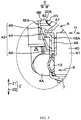
- Fig. 3 is an amplifying diagram illustrating a main part surrounded by a circle in Fig. 2 .
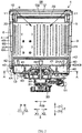
- Fig. 4 is a section view in A-A direction of Fig. 2 . The following description refers to Fig. 2 and Fig. 3 mainly.
- the washing machine 1 includes a motor 30 which generates a torque by power drive.
- the motor 30 is configured at the lower side Z2 of the bottom wall 7 of the outer tank 3 in the enclosure 2.
- the motor 30 has an output shaft 31 for outputting torque.
- the output shaft 31 extends to the upper side Z1 from the motor 30.
- a transmission shaft 32 extending to the upper side Z1 is coaxially configured at the upper side Z1 of the output shaft 31.
- the output shaft 31 is connected with the transmission shaft 32 by a transmission mechanism 33 composed of a retarding mechanism and the like.
- the transmission shaft 32 passes through a center part of a circle of the bottom wall 7 of the outer tank 3 and extends to the upper side Z1. An upper end part of the transmission shaft 32 is connected with the center part of the circle of the bottom wall 21 of the washing tank 5. Torque generated by the motor 30 is delivered to the transmission shaft 32 via the output shaft 31 and the transmission mechanism 33. Therefore, the washing tank 5 takes the transmission shaft 32 as a rotary center to rotate together with the transmission shaft 32. The rotary direction of the washing tank 5 is consistent with the circumference S.
- the washing tank 5 rotates under a state that detergent has been dissolved in water stored in the outer tank 3. Thus, the washing operation of washings contained in the washing tank 5 is executed. After the washing operation, the washing tank 5 rotates under a state that the outer tank 3 supplies water. Therefore, rinsing operation of washings contained in the washing tank 5 is executed. The washing tank 5 rotates at a high speed under a state of performing drainage of the outer tank 3. Therefore, the dewatering operation of washings contained in the washing tank 5 is executed.
- a plurality of blades 40 protruded to the lower side Z2 are integrally arranged on the lower surface 21A of the bottom wall 21 of the washing tank 5.
- Each blade 40 is formed in a plate shape which is thin in the circumference S and which linearly extends along the radial direction R; and the blades 40 are radially configured (refer to Fig. 4 ) by using the center of the circle of the bottom wall 21 as a reference.
- the blades 40 are made from resin and integrally formed with the bottom wall 21. Under a state of not contacting with the outer tank 3, the blades 40 are configured at the gap 41 between the bottom wall 21 and the bottom wall 7 of the outer tank 3 along the up-down direction Z.
- the receiving port 13 at the lower end part 4A of each water path 4 is arranged near the bottom wall 21 of the washing tank 5. Specifically, the receiving port 13 is set to be as high as the blades 40.
- the blades 40 at the bottom wall 21 of the washing tank 5 rotate integrally with the washing tank 5. Therefore, the blades 40 feed water stored in the outer tank 3. Specifically, water stored in the gap between the bottom wall 21 of the washing tank 5 and the bottom wall 7 of the outer tank 3 is delivered into the receiving port 13 of each water path 4. Thus, water stored in the outer tank 3 is continuously delivered to the receiving port 13 of each water path 4 through the rotating blades 40; and water is received into the water paths 4 by the receiving port 3.
- Water received into the water path 4 is pushed by subsequent water. Therefore, water rises in the water paths 4. Water rising to the upper end part 4C of the water paths 4 flows into the inner space 10 of the annular wall 8 from the protrusions 12 (refer to Fig. 1 ) of the annular wall 8 of the outer tank 3. As shown by a dotted arrow, water is drained into the washing tank 5 from the exhaust port 11 at the inner periphery part of the annular wall 8 and falls to an inclined down direction in the washing tank 5.
- the water paths 4 absorb water stored in the outer tank 3; and the exhaust port 11 drains water absorbed by the water paths 4 into the washing tank 5 from the upper side Z1. Water in the washing tank 5 passes through the through holes 23 of the washing tank 5. Therefore, water flows between the washing tank 5 and the outer tank 3.
- washings in the washing tanks 5 are stirred by the rotating washing tank 5 and water drained from the upper side Z1.
- detergent in the washing tank 5 can blister through drainage of water and falling strength in the washing tank 5. Therefore, washings can be effectively washed by the blistering detergent.
- water drained into the washing tank 5 from the upper side Z1 mechanical force generated by water falling is applied to washings, clearing power can be improved, and washings can be rinsed effectively, and thus the rinsing operation time can be shortened.
- the blades 40 integrally arranged at the bottom wall 21 of the washing tank 5 rotate integrally with the washing tank 5.
- water stored in the outer tank 3 is delivered into the receiving port 13 of the water paths 4 as shown by a bold line arrow. Therefore, water in the outer tank 3 can be largely delivered into the water paths 4 by a synergistic effect of centrifugal force generated on water in the outer tank 3 due to the rotation of the washing tank 5 and the blades 40.
- quantity of water absorbed by the water paths 4 can be increased.
- the blades 40 are integrally arranged at the washing tank 5, no other part is required to be arranged if the blades 40 are integrally formed with the washing tank 5 as described above. In addition, since the blades 40 and the washing 5 rotate integrally, no mechanism for rotating the blades 40 independently need to be arranged. Thus, the number of parts can be reduced in a structure for absorbing water and draining water into the washing tank 5.
- Water in the outer tank 3 can be largely absorbed by a plurality of water paths 4. Since each water path 4 is arranged at the peripheral surface 6A of the side wall 6 of the outer tank 3, namely, outside the outer tank 3, the water paths 4 can be freely designed compared with a condition that the water paths 4 are arranged in the outer tank 3. Thus, the pressure and flow rate of water absorbed by the water paths 4 can be freely regulated. Specifically, if the water paths 4 are thickened and the inner spaces of the water paths 4 are enlarged, water quantity can be increased; and if the water paths 4 are thinned and the inner spaces of the water paths 4 are reduced, water pressure can be increased.
- the receiving port 13 of each water path 4 is arranged near the bottom wall 21 of the washing tank 5, so the receiving port is directly located at the position for receiving water stored in the outer tank 3. Therefore, quantity of water absorbed by the water paths 4 can be increased by largely receiving water in the outer tank 3 through the receiving port 13. Specifically, since the receiving port 13 of the water path 4 is set to be as high as the blades 40, the receiving port 13 is located near the blades 40 for delivering water into the water paths 4. Therefore, quantity of water absorbed by the water paths 4 can be increased by receiving a great number of water delivered by the blades 40 through the receiving port 13.
- the gap 42 is ensured between the inner peripheral surface 6B of the side wall 6 of the outer tank 3 and the outer peripheral surface 20A of the side wall 20 of the washing tank 5.
- the gap 42 is formed in a ring extending along the circumference S and enclosing the washing tank 5. It can be imagined that water can overflow to the gap 42 at the upper side Z1 of the receiving port 13 when water stored in the outer tank 3 is delivered into the receiving port 13 by the rotating blades 40. Therefore, the labyrinth structure 43 for preventing water from overflowing to the gap 42 is arranged on the washing machine 1.
- the labyrinth structure 43 includes one part of the lower end part of the inner peripheral surface 6B of the side wall 6 of the outer tank 3, namely, a flat surface 44 extending to the outer side in the radial direction R.
- the flat surface 44 is located at the upper side Z1 of the receiving port 13.
- the labyrinth structure 43 further includes a transverse flange 45 extending from the low end part of the outer peripheral surface 20A of the side wall 20 of the washing tank 5 to the outer side of the radial direction R and an annular vertical flange 46 extending from the whole domain of the circumference S at the lower end of the side wall 20 to the lower side Z2.
- the transverse flange 45 is formed in a thin-plate shape in the up-down direction Z.
- the transverse flange 45 can also be form in a ring extending along the circumference S.
- the lower surface 45A of the transverse flange 45 is opposite to the flat surface 44 from the upper side Z1 across the gap 47, and the lower surface 45A and the flat surface 44 extend in parallel along the horizontal direction H.
- the gap 47 is a thin space along the up-down direction Z.
- the lower end of the vertical flange 46 is located at the upper side Z1 of the receiving port 13 of each water path 4.
- Each blade 40 is convexly configured at the lower side Z2 of the lower end of the vertical flange 46.
- the outside end part of each blade 40 in the radial direction R and the vertical flange 46 are located at the same position; and each blade 40 is configured to be near the receiving port 13 of the water paths 40 from the inner side of the radial direction R.
- the vertical flange 46 is opposite to the part of the lower side Z2 of the flat surface 44 relative to the inner peripheral surface 6B of the side wall 6 and the whole domain of circumference S from the inner side of the radial direction R across the gap 48.
- the gap 48 is the thin annular space in radial direction R; and the lower side Z2 is communicated with the inner side of gap 47 in radial direction R.
- the gaps 47 and 48 are the narrowest parts in the gap between the outer tank 3 and the washing tank 5.
- water stored in the outer tank 3 must rise in the gap 48 firstly; then a flowing direction of the water is changed in a roughly right angle at the upper end part of the gap 48; and the water flows through the gap 47 along the radial direction R. Therefore, water stored in the outer tank 3 is hard to reach the gap 42 across the gaps 47 and 48.
- the gap 42 is enlarged in a ladder manner (refer to Fig. 2 ) to an outer side of the radial direction R as the gap 42 faces the upper side Z1.
- the receiving port 13 of each water path 4 is configured to face a direction between a normal direction P relative to the circumference S and a tangential direction Q relative to the circumference S. That is to say, the receiving port 13 is configured to face the inclined direction K towards the normal direction P and the tangential direction Q. It shall be noted that the washing tank 5 in the present embodiment rotates in a direction reverse to the direction of the receiving port 13 (anti-clockwise direction in Fig. 4 ).
- the receiving port 13 of the water path 4 is located at a flowing target of water delivered by the blades 40 integrally rotating with the washing tank. Therefore, quantity of water absorbed by the water paths 4 can be increased by receiving a large number of water delivered by the blades 40 through the receiving port 13.
- Fig. 5 is a diagram illustrating the first variation example applied to Fig. 4 .
- a drainage port 50 for draining water in the outer tank 3 is formed in one position on the circumference S at the bottom wall 7 of the water tank 3.
- the drainage port 50 is connected with a drainage path 51 (refer to Fig. 2 ) for draining out of the washing machine 1.
- An overflow port 52 for overflowing water above the specified water level in the outer tank 3 to overflow out of the outer tank 3 is formed in the position at the side wall 6 of the outer tank 3 away from the bottom wall 7 to the upper side Z1 by a specified distance.
- the overflow port 52 is connected with an overflow path 53 for leading water overflowing from the overflow port 52 to the drainage path 51.
- Each water path 4 is preferably separate from the drainage port 50 and the overflow port 52.
- the drainage port 50 and the overflow port 52 are respectively configured between two adjacent water paths 4 in the circumference S. More preferably, the drainage port 50 and the overflow port 52 are respectively configured at a position where the drainage port 50 and the overflow port 52 are spaced by a roughly equal distance from the adjacent water path 4 in the circumference S.
- Fig. 6 is a diagram illustrating the second variation example applied to Fig. 4 .
- each blade 40 at the lower surface 21A of the bottom wall 21 of the washing tank 5 is formed in a plate shape which is thin in the circumference S and which extends linearly along the radial direction R, and the blades 40 are radially configured by taking the center of the circle of the bottom wall 21 (refer to Fig. 4 and Fig. 5 ) as a reference.
- the blades 40 can also be formed in the plate shape which is thin in the circumference S and which bends and extends crossed with the radial direction R from the lower side Z2 through observation.
- each blade 40 observed from the lower side Z2, is radially configured by taking the center of the circle of the bottom wall 21 as a reference; and the blades are bent in such a manner that one side of the blade faces the outer side of the radial direction R and the other side faces the same direction of the circumference S (anti-clockwise direction in Fig. 6 ).
- number of the water paths 4 is four, and can be freely altered.
- each water path 4 can have different shape.
- the blades 40 are integrally formed with the bottom wall 21 of the washing tank 5, or can also be fixed on the bottom wall 21 by screws and other connection components after the blades 40 are independently formed with the bottom wall 21.
- the receiving port 13 of each water path 4 is configured to face a direction between the normal direction P relative to the circumference S and the tangential direction Q relative to the circumference S (refer to Fig. 4 ).
- the receiving port 13 is configured to face the normal direction P.
- washings in the washing tank 5 is stirred by the rotating washing tank 5 and water drained by the water paths 4 from the upper side Z1.
- a rotating stirrer can be additionally arranged in the washing tank 5.
- the bottom wall 21 of the washing tank 5 may be not fully made from resin; and the part connected with the transmission shaft 32 can be made of metal.
- the washing tank 5 can also be obliquely configured in such a manner that the rotating center of the washing tank 5 obliquely extends relative to the up-down direction Z.
Landscapes
- Engineering & Computer Science (AREA)
- Textile Engineering (AREA)
- Main Body Construction Of Washing Machines And Laundry Dryers (AREA)
- Detail Structures Of Washing Machines And Dryers (AREA)
- Accessory Of Washing/Drying Machine, Commercial Washing/Drying Machine, Other Washing/Drying Machine (AREA)
- Cleaning By Liquid Or Steam (AREA)
Abstract
Description
- The present invention relates to a washing machine.
- In a washing machine in the following
patent literature 1, a rotary wing for stirring washings is rotationally and freely arranged at a bottom of a washing/dewatering tank; and a pumping wing is rotationally and freely arranged below the rotary wing. - A drive shaft of a drive motor is directly connected with the rotary wing; and the pumping wing is connected with the rotary wing by a planetary gear mechanism. After being delivered to the rotary wing, a torque of the drive motor is delivered to the pumping wing by the planetary gear mechanism.
- A pumping path is arranged on an inner side wall of the washing/dewatering tank. When the pumping wing rotates, a detergent stored in the washing/dewatering tank is sent into the pumping path by the pumping wing and rises in the pumping path; and then detergent is returned into the washing/dewatering tank from an exhaust port of the pumping path.
- Patent literature 1: Japan specifically disclosed No.
2010-94248 - In the washing machine in the following
patent literature 1, to deliver detergent stored in the washing/dewatering tank back to the washing/dewatering tank by the pumping path, the pumping ring and the planetary gear mechanism for delivering torque to the pumping wing from the rotary wing need to be arranged, so the number of parts is increased. - The present invention is achieved under such background. The present invention aims at providing a washing machine capable of reducing the number of parts in a structure for absorbing water and draining water into the washing tank.
- The washing machine provided in the present invention includes an outer tank capable of storing water; a washing tank contained in the outer tank, having a through hole for allowing water to flow between the washing tank and the outer tank and used for containing washings and rotatable; water paths for absorbing water stored in the outer tank; an exhaust port for draining water absorbed through water paths into the washing tank from above; and blades integrally arranged on a bottom wall of the washing tank to deliver water stored in the outer tank into water paths by rotating with the washing tank integrally.
- In addition, in the present invention, a plurality of the water paths are arranged at an outer side of the outer tank.
- In addition, in the present invention, receiving ports in the water paths to receive water stored in the outer tank are arranged near the bottom wall of the washing tank.
- In addition, in the present invention, the receiving ports are set to be as high as the blades.
- In addition, in the present invention, the receiving ports are configured to face a direction between a normal direction relative to a rotary direction of the washing tank and a tangential direction relative to the rotary direction.
- In addition, in the present invention, a labyrinth structure, for preventing water stored in the outer tank from leaking to a gap between the outer tank and the washing tank above the receiving ports, is arranged.
- In addition, in the present invention, the outer tank is formed with a drainage port for draining water in the outer tank, and an overflow port for allowing water above a specified water level in the outer tank to overflow outside the outer tank; and water paths, the drainage port and the overflow port are respectively separated.
- According to the present invention, the washing tank for containing washings can be rotationally contained in the outer tank in the washing machine. The water paths can absorb water stored in the outer tank. The absorbed water can be drained to the washing tank by the drainage port from above. The washing in the washing tank passes through the through hole of the washing tank. Therefore, water can flow between the washing tank and the outer tank.
- Thus, water can be used for washing when circulating, and thus water can be saved. In addition, when washings are washed, detergent in the washing tank can blister through drainage of water and falling strength in the washing tank. Therefore, washings can be effectively washed by the blistering detergent. In addition, clearing power can be improved by water drained from the washing tank from the above and mechanical force, generated by water falling, acting on washings; washings can be rinsed effectively, and thus the rinsing operation time can be shortened.
- The bottom wall of the washing tank is integrally provided with blades which rotate integrally with the washing tank for delivering water stored in the outer tank into the water paths. Thus, water in the outer tank can be largely delivered into the water paths by a synergistic effect of centrifugal force generated on water in the outer tank due to the rotation of the washing tank and the blades. Thus, quantity of water absorbed by the water paths can be increased.
- Since the blades are integrally arranged on the washing tank, if the blades and the washing tank are integrally formed, other parts are not arranged again. In addition, since the blades and the washing tank rotate integrally, a mechanism for rotating the blades independently is not arranged. Therefore, the number of the parts can be reduced in a structure for absorbing water and draining water into the washing tank.
- In addition, according to the present invention, water in the outer tank can be largely absorbed through a plurality of water paths. In addition, under a condition that the water paths are arranged at the outer side of the outer tank, compared with a condition that the water paths are arranged in the outer tank, since the water paths can be freely designed, the pressure and flow rate of water absorbed by the water paths can be freely regulated.
- In addition, according to the present invention, since the receiving ports of the water paths are arranged near the bottom wall of the washing tank, the receiving ports are located at a position for directly receiving water stored in the outer tank. Therefore, quantity of water absorbed by the water paths can be increased by largely receiving water in the outer tank by the receiving ports.
- In addition, according to the present invention, since the receiving ports of the water paths are set to be as high as the blades, the receiving ports are located at the position near the blades for delivering water into the water paths. Therefore, quantity of water absorbed by the water paths can be increased by largely receiving water delivered by the blades at the receiving ports.
- In addition, according to the present invention, since the receiving ports of the water paths are confirmed to face a direction between the normal direction relative to the rotary direction of the washing tank and a tangential direction relative to the rotary direction, the receiving ports are located at a flowing destination of water delivered by the rotary blades. Therefore, quantity of water absorbed by the water paths can be increased by largely receiving water delivered by the blades at the receiving ports.
- In addition, according to the present invention, the labyrinth structure can restrain water stored in the outer tank to overflow to the gap between the outer tank and the washing tank above the receiving port of the water paths. Thus, water delivered by the blades can be effectively received at the receiving ports instead of overflowing to the gap between the outer tank and the washing tank; and thus quantity of water absorbed by the water paths can be increased.
- In addition, according to the present invention, the water paths, the drainage port and the overflow port are respectively separated. Therefore, water stored in the outer tank is not affected by water flowing through steps near the drainage port and the overflow port; and water is stably absorbed and drained into the washing tank.
-
-
Fig. 1 is a stereoscopic diagram illustrating an internal structure of awashing machine 1 of one embedment observed from above in the present invention; -
Fig. 2 is a vertical section view illustrating an internal structure of awashing machine 1; -
Fig. 3 is an amplifying diagram illustrating a main part ofFig. 2 ; -
Fig. 4 is a section view in A-A direction ofFig. 2 ; -
Fig. 5 is a diagram illustrating a first variation example applied toFig. 4 ; -
Fig. 6 is a diagram illustrating a second variation example applied toFig. 4 . - A list of reference numerals:
- 1: washing machine;
- 3: outer tank;
- 4: water path;
- 5: washing tank;
- 6A: peripheral surface;
- 11: exhaust port;
- 13: receiving port;
- 21: bottom wall;
- 23: through hole;
- 40: blade;
- 42: gap;
- 43: labyrinth structure;
- 50: drainage port;
- 52: overflow port;
- P: normal direction;
- Q: tangential direction;
- S: circumference;
- Z1: upper side.
- An implementation mode of the present invention is specifically explained below with reference to drawings.
-
Fig. 1 is a stereoscopic diagram illustrating an internal structure of awashing machine 1 of one embedment observed from above in the present invention. - It should be noted that a gesture of a
washing machine 1 inFig. 1 prevails under a condition of mentioning a direction of thewashing machine 1. An up-down direction inFig. 1 is consistent with an up-down direction Z (vertical) of thewashing machine 1. A left-right direction inFig. 1 is consistent with a left-right direction X of thewashing machine 1. In the up-down direction Z, an upper side is called as an upper side Z1 and a lower side is called as a lower side Z2. In the left-right direction X, a left side is called as a left side X1 and a right side is called as a right side X2. An orthogonal direction of the up-down direction Z and the left-right direction X is a front-rear direction Y of thewashing machine 1. In the front-rear direction Y, a front side is called as a front side Y1 and a rear side is called as a rear side Y2. The left-right direction X as well as the front-rear direction Y are included in a horizontal direction H (transverse). - The
washing machine 1 includes anenclosure 2, anouter tank 3,water paths 4 and awashing tank 5. - The
enclosure 2 is a hollow body with a roughly cuboid shape; and theouter tank 3, thewater paths 4 and thewashing tank 5 are contained in theenclosure 2. - The
outer tank 3 is supported by theenclosure 2 through a plurality of hanger rods (not shown in the drawings) with springs and damping mechanisms. Theouter tank 3 is in a cylindrical shape having an axis extending along the up-down direction Z, and is made from resin. A circumference of the cylindricalouter tank 3 is called as a circumference S; and a radial direction of theouter tank 3 is called as a radial direction R. Theouter tank 3 has acylindrical side wall 6 extending along the up-down direction Z, adiscoid bottom wall 7 flatly extending along the horizontal direction H and blocking a lower end of theside wall 6, and anannular wall 8 extending fully to an inner side of radial direction R from the upper end of theside wall 6 and the circumference S. Aperipheral surface 6A of theside wall 6 is an outer side of theouter tank 3. Water can be stored in theouter tank 3 from the side of thebottom wall 7. - An
opening 9 divided by an inner periphery of theannular wall 8 is formed on the upper end of theouter tank 3. The inner part of theouter tank 3 is exposed to the upper side Z1 by theopening 9. Theannular wall 8 has aninner space 10 extending along the circumference S and anexhaust port 11 for cutting the inner periphery part of theannular wall 8 along the circumference S and exposing theinner space 10 to the inner side of the radial direction R. Theannular wall 8 has a plurality of (four, herein)protrusions 12. A plurality ofprotrusions 12 are separated in the circumference S. It is observed from the upper side Z1 that the protrusions extend in a roughly triangular shape from an outer periphery part of theannular wall 8 to the outer side of the radial direction R. Eachprotrusion 12 is a hollow body forming one part of theinner space 10; and theprotrusions 12 are respectively arranged at four corners of the roughlyquadrangular enclosure 2 when being viewed from above in configuration. - The
water paths 4 are slender tubes made from resin; and a plurality of water paths are arranged on theperipheral surface 6A of theside wall 6 in such a manner that the quantity of the water paths is the same as that (four herein) of theprotrusions 12. Eachwater path 4 has alower end part 4A extending from the lower end part of theside wall 6 of theouter tank 3 to the outer side of the radial direction R along the horizontal direction H, amiddle part 4B bending from thelower end part 4A and extending to the upper side Z1 along theperipheral surface 6A, and anupper end part 4C extending from themiddle part 4B to the upper side Z1 and connected with theprotrusion 12 from the lower side Z2. Themiddle part 4B does not need to extend linearly along the up-down direction Z, and can be bent at one side or can extend along the upper side Z1 by a bent side. - Like the
protrusions 12, thewater paths 4 are respectively configured at four corners of theenclosure 2. Eachwater path 4 has a receivingport 13 at a connection part of thelower end part 4A and theside wall 6 of theouter tank 3; and the inner space of eachwater path 4 is communicated with the inner part of theouter tank 3 by the receivingport 13. The inner space of eachwater path 4 is communicated with theinner space 10 of theannular wall 8 of theouter tank 3 by the connection part of theupper end part 4C and theprotrusion 12. - The
washing tank 5 is formed as a cylindrical shape having the axis extending along the up-down direction Z, and is slightly smaller than theouter tank 3. Washings are contained in thewashing tank 5. Thewashing tank 5 has ametal side wall 20 forming the cylindrical shape extending along the up-down direction Z; aresin bottom wall 21 flatly extending along the horizontal direction H, blocking the lower end of theside wall 20 and forming the discoid shape; and aresin balancing ring 22 assembled at the upper end of thewashing tank 5. A plurality of throughholes 23 are respectively formed in theside wall 20 andbottom wall 21. - The balancing
ring 22 is an annular hollow body having an inner space for containing liquid and is coaxially assembled with the upper end part of theside wall 20. As described below, when thewashing tank 5 rotates, the rotary balance of thewashing tank 5 is maintained by the movement of the liquid in the balancingring 22. Theopening 24 divided by the inner periphery of the balancingring 22 is formed at the upper end of thewashing tank 5. The inner part of thewashing tank 5 is exposed to the upper side Z1 through theopening 24. - The
washing tank 5 is contained in theouter tank 3 and is almost coaxially configured with theouter tank 3. Therefore, the circumference of thewashing tank 5 is the circumference S and the radial direction of thewashing tank 5 is the radial direction R. Theopening 24 of thewashing tank 5 is communicated with the opening of theouter tank 3 from the lower side Z2. Theopenings access 25 of washings. Washings can be throw into and take out of thewashing tank 5 from the upper side Z1 through theaccess 25 by users of thewashing machine 1. In thewashing tank 5 contained in theouter tank 3, thebottom wall 21 is opposite to thebottom wall 7 of theouter tank 3 from the upper side Z1 by separating a gap. - Water stored in the
outer tank 3 passes through the throughholes 23 respectively located in theside wall 20 andbottom wall 21 of thewashing tank 5; therefore, water can flow between theouter tank 3 and thewashing tank 5. Thus, a water level in thewater tank 3 is approximately consistent with a water level in thewashing tank 5. -
Fig. 2 is a vertical section view illustrating an internal structure of awashing machine 1.Fig. 3 is an amplifying diagram illustrating a main part surrounded by a circle inFig. 2 .Fig. 4 is a section view in A-A direction ofFig. 2 . The following description refers toFig. 2 andFig. 3 mainly. - The
washing machine 1 includes amotor 30 which generates a torque by power drive. Themotor 30 is configured at the lower side Z2 of thebottom wall 7 of theouter tank 3 in theenclosure 2. Themotor 30 has anoutput shaft 31 for outputting torque. Theoutput shaft 31 extends to the upper side Z1 from themotor 30. Atransmission shaft 32 extending to the upper side Z1 is coaxially configured at the upper side Z1 of theoutput shaft 31. Theoutput shaft 31 is connected with thetransmission shaft 32 by atransmission mechanism 33 composed of a retarding mechanism and the like. - The
transmission shaft 32 passes through a center part of a circle of thebottom wall 7 of theouter tank 3 and extends to the upper side Z1. An upper end part of thetransmission shaft 32 is connected with the center part of the circle of thebottom wall 21 of thewashing tank 5. Torque generated by themotor 30 is delivered to thetransmission shaft 32 via theoutput shaft 31 and thetransmission mechanism 33. Therefore, thewashing tank 5 takes thetransmission shaft 32 as a rotary center to rotate together with thetransmission shaft 32. The rotary direction of thewashing tank 5 is consistent with the circumference S. - The
washing tank 5 rotates under a state that detergent has been dissolved in water stored in theouter tank 3. Thus, the washing operation of washings contained in thewashing tank 5 is executed. After the washing operation, thewashing tank 5 rotates under a state that theouter tank 3 supplies water. Therefore, rinsing operation of washings contained in thewashing tank 5 is executed. Thewashing tank 5 rotates at a high speed under a state of performing drainage of theouter tank 3. Therefore, the dewatering operation of washings contained in thewashing tank 5 is executed. - Associated with the water paths, a plurality of
blades 40 protruded to the lower side Z2 are integrally arranged on thelower surface 21A of thebottom wall 21 of thewashing tank 5. Eachblade 40 is formed in a plate shape which is thin in the circumference S and which linearly extends along the radial direction R; and theblades 40 are radially configured (refer toFig. 4 ) by using the center of the circle of thebottom wall 21 as a reference. Theblades 40 are made from resin and integrally formed with thebottom wall 21. Under a state of not contacting with theouter tank 3, theblades 40 are configured at thegap 41 between thebottom wall 21 and thebottom wall 7 of theouter tank 3 along the up-down direction Z. - The receiving
port 13 at thelower end part 4A of eachwater path 4 is arranged near thebottom wall 21 of thewashing tank 5. Specifically, the receivingport 13 is set to be as high as theblades 40. - When the
washing tank 5 rotates by receiving torque of themotor 30, theblades 40 at thebottom wall 21 of thewashing tank 5 rotate integrally with thewashing tank 5. Therefore, theblades 40 feed water stored in theouter tank 3. Specifically, water stored in the gap between thebottom wall 21 of thewashing tank 5 and thebottom wall 7 of theouter tank 3 is delivered into the receivingport 13 of eachwater path 4. Thus, water stored in theouter tank 3 is continuously delivered to the receivingport 13 of eachwater path 4 through therotating blades 40; and water is received into thewater paths 4 by the receivingport 3. - Water received into the
water path 4 is pushed by subsequent water. Therefore, water rises in thewater paths 4. Water rising to theupper end part 4C of thewater paths 4 flows into theinner space 10 of theannular wall 8 from the protrusions 12 (refer toFig. 1 ) of theannular wall 8 of theouter tank 3. As shown by a dotted arrow, water is drained into thewashing tank 5 from theexhaust port 11 at the inner periphery part of theannular wall 8 and falls to an inclined down direction in thewashing tank 5. - Like this, the
water paths 4 absorb water stored in theouter tank 3; and theexhaust port 11 drains water absorbed by thewater paths 4 into thewashing tank 5 from the upper side Z1. Water in thewashing tank 5 passes through the throughholes 23 of thewashing tank 5. Therefore, water flows between thewashing tank 5 and theouter tank 3. - Thus, water circulates when water is used for washing, and thus water can be saved. Washings in the
washing tanks 5 are stirred by therotating washing tank 5 and water drained from the upper side Z1. In addition, when washings are washed, detergent in thewashing tank 5 can blister through drainage of water and falling strength in thewashing tank 5. Therefore, washings can be effectively washed by the blistering detergent. In addition, by water drained into thewashing tank 5 from the upper side Z1, mechanical force generated by water falling is applied to washings, clearing power can be improved, and washings can be rinsed effectively, and thus the rinsing operation time can be shortened. - As shown in
Fig. 4 , theblades 40 integrally arranged at thebottom wall 21 of thewashing tank 5 rotate integrally with thewashing tank 5. Thus, water stored in theouter tank 3 is delivered into the receivingport 13 of thewater paths 4 as shown by a bold line arrow. Therefore, water in theouter tank 3 can be largely delivered into thewater paths 4 by a synergistic effect of centrifugal force generated on water in theouter tank 3 due to the rotation of thewashing tank 5 and theblades 40. Thus, quantity of water absorbed by thewater paths 4 can be increased. - Since the
blades 40 are integrally arranged at thewashing tank 5, no other part is required to be arranged if theblades 40 are integrally formed with thewashing tank 5 as described above. In addition, since theblades 40 and thewashing 5 rotate integrally, no mechanism for rotating theblades 40 independently need to be arranged. Thus, the number of parts can be reduced in a structure for absorbing water and draining water into thewashing tank 5. - Water in the
outer tank 3 can be largely absorbed by a plurality ofwater paths 4. Since eachwater path 4 is arranged at theperipheral surface 6A of theside wall 6 of theouter tank 3, namely, outside theouter tank 3, thewater paths 4 can be freely designed compared with a condition that thewater paths 4 are arranged in theouter tank 3. Thus, the pressure and flow rate of water absorbed by thewater paths 4 can be freely regulated. Specifically, if thewater paths 4 are thickened and the inner spaces of thewater paths 4 are enlarged, water quantity can be increased; and if thewater paths 4 are thinned and the inner spaces of thewater paths 4 are reduced, water pressure can be increased. - As shown in
Fig. 3 , the receivingport 13 of eachwater path 4 is arranged near thebottom wall 21 of thewashing tank 5, so the receiving port is directly located at the position for receiving water stored in theouter tank 3. Therefore, quantity of water absorbed by thewater paths 4 can be increased by largely receiving water in theouter tank 3 through the receivingport 13. Specifically, since the receivingport 13 of thewater path 4 is set to be as high as theblades 40, the receivingport 13 is located near theblades 40 for delivering water into thewater paths 4. Therefore, quantity of water absorbed by thewater paths 4 can be increased by receiving a great number of water delivered by theblades 40 through the receivingport 13. - To make the
washing tank 5 smoothly rotate in theouter tank 3, thegap 42 is ensured between the innerperipheral surface 6B of theside wall 6 of theouter tank 3 and the outerperipheral surface 20A of theside wall 20 of thewashing tank 5. Thegap 42 is formed in a ring extending along the circumference S and enclosing thewashing tank 5. It can be imagined that water can overflow to thegap 42 at the upper side Z1 of the receivingport 13 when water stored in theouter tank 3 is delivered into the receivingport 13 by therotating blades 40. Therefore, thelabyrinth structure 43 for preventing water from overflowing to thegap 42 is arranged on thewashing machine 1. - The
labyrinth structure 43 includes one part of the lower end part of the innerperipheral surface 6B of theside wall 6 of theouter tank 3, namely, aflat surface 44 extending to the outer side in the radial direction R. Theflat surface 44 is located at the upper side Z1 of the receivingport 13. Thelabyrinth structure 43 further includes atransverse flange 45 extending from the low end part of the outerperipheral surface 20A of theside wall 20 of thewashing tank 5 to the outer side of the radial direction R and an annularvertical flange 46 extending from the whole domain of the circumference S at the lower end of theside wall 20 to the lower side Z2. - The
transverse flange 45 is formed in a thin-plate shape in the up-down direction Z. Thetransverse flange 45 can also be form in a ring extending along the circumference S. The lower surface 45A of thetransverse flange 45 is opposite to theflat surface 44 from the upper side Z1 across thegap 47, and the lower surface 45A and theflat surface 44 extend in parallel along the horizontal direction H. Thegap 47 is a thin space along the up-down direction Z. - The lower end of the
vertical flange 46 is located at the upper side Z1 of the receivingport 13 of eachwater path 4. Eachblade 40 is convexly configured at the lower side Z2 of the lower end of thevertical flange 46. The outside end part of eachblade 40 in the radial direction R and thevertical flange 46 are located at the same position; and eachblade 40 is configured to be near the receivingport 13 of thewater paths 40 from the inner side of the radial direction R. Thevertical flange 46 is opposite to the part of the lower side Z2 of theflat surface 44 relative to the innerperipheral surface 6B of theside wall 6 and the whole domain of circumference S from the inner side of the radial direction R across the gap 48. The gap 48 is the thin annular space in radial direction R; and the lower side Z2 is communicated with the inner side ofgap 47 in radial direction R. - The
gaps 47 and 48 are the narrowest parts in the gap between theouter tank 3 and thewashing tank 5. In addition, before arriving at thegap 42 of the upper side Z1 of the receivingport 13 of eachwater path 4, water stored in theouter tank 3 must rise in the gap 48 firstly; then a flowing direction of the water is changed in a roughly right angle at the upper end part of the gap 48; and the water flows through thegap 47 along the radial direction R. Therefore, water stored in theouter tank 3 is hard to reach thegap 42 across thegaps 47 and 48. - Therefore, since water is not allowed to overflow to the
gap 42 between theouter tank 3 and thewashing tank 5, water delivered by theblades 40 can be effectively received by the receivingport 13. Thus, quantity of water absorbed by thewater paths 4 can be increased. It shall be noted that since the lower end parts of thegaps 47 and 48 have little vibration in thewashing tank 5 when thewashing tank 5 rotates, therotary washing tank 5 does not contact with theouter tank 3 even if thegaps 47 and 48 are narrow. On the other hand, to prevent the upper part with great vibration in therotary washing tank 5 from contacting with theouter tank 3, thegap 42 is enlarged in a ladder manner (refer toFig. 2 ) to an outer side of the radial direction R as thegap 42 faces the upper side Z1. - Referring to the
water paths 4 located at left end inFig. 4 , the receivingport 13 of eachwater path 4 is configured to face a direction between a normal direction P relative to the circumference S and a tangential direction Q relative to the circumference S. That is to say, the receivingport 13 is configured to face the inclined direction K towards the normal direction P and the tangential direction Q. It shall be noted that thewashing tank 5 in the present embodiment rotates in a direction reverse to the direction of the receiving port 13 (anti-clockwise direction inFig. 4 ). - In this case, the receiving
port 13 of thewater path 4 is located at a flowing target of water delivered by theblades 40 integrally rotating with the washing tank. Therefore, quantity of water absorbed by thewater paths 4 can be increased by receiving a large number of water delivered by theblades 40 through the receivingport 13. -
Fig. 5 is a diagram illustrating the first variation example applied toFig. 4 . - Referring to
Fig. 5 , adrainage port 50 for draining water in theouter tank 3 is formed in one position on the circumference S at thebottom wall 7 of thewater tank 3. Thedrainage port 50 is connected with a drainage path 51 (refer toFig. 2 ) for draining out of thewashing machine 1. Anoverflow port 52 for overflowing water above the specified water level in theouter tank 3 to overflow out of theouter tank 3 is formed in the position at theside wall 6 of theouter tank 3 away from thebottom wall 7 to the upper side Z1 by a specified distance. Theoverflow port 52 is connected with anoverflow path 53 for leading water overflowing from theoverflow port 52 to thedrainage path 51. - Each
water path 4 is preferably separate from thedrainage port 50 and theoverflow port 52. Specifically, thedrainage port 50 and theoverflow port 52 are respectively configured between twoadjacent water paths 4 in the circumference S. More preferably, thedrainage port 50 and theoverflow port 52 are respectively configured at a position where thedrainage port 50 and theoverflow port 52 are spaced by a roughly equal distance from theadjacent water path 4 in the circumference S. Through such a structure, water stored in theouter tank 3 can be stably absorbed and drained into thewashing tank 5 instead of being affected by water flowing through thesteps 60 near thedrainage port 50 and theoverflow port 52. -
Fig. 6 is a diagram illustrating the second variation example applied toFig. 4 . In the above embodiment and the first variation example, eachblade 40 at thelower surface 21A of thebottom wall 21 of thewashing tank 5 is formed in a plate shape which is thin in the circumference S and which extends linearly along the radial direction R, and theblades 40 are radially configured by taking the center of the circle of the bottom wall 21 (refer toFig. 4 andFig. 5 ) as a reference. However, as shown inFig. 6 , theblades 40 can also be formed in the plate shape which is thin in the circumference S and which bends and extends crossed with the radial direction R from the lower side Z2 through observation. Specifically, eachblade 40, observed from the lower side Z2, is radially configured by taking the center of the circle of thebottom wall 21 as a reference; and the blades are bent in such a manner that one side of the blade faces the outer side of the radial direction R and the other side faces the same direction of the circumference S (anti-clockwise direction inFig. 6 ). - The present invention is not limited to the contents of the above embodiments, and can be changed within the scope recorded in claims.
- For example, in the above embodiment, number of the
water paths 4 is four, and can be freely altered. In addition, eachwater path 4 can have different shape. - The
blades 40 are integrally formed with thebottom wall 21 of thewashing tank 5, or can also be fixed on thebottom wall 21 by screws and other connection components after theblades 40 are independently formed with thebottom wall 21. - As described above, under a condition that the
washing tank 5 rotates to the direction reverse to that of the receivingport 13, the receivingport 13 of eachwater path 4 is configured to face a direction between the normal direction P relative to the circumference S and the tangential direction Q relative to the circumference S (refer toFig. 4 ). Under a condition that thewashing tank 5 rotates along the positive and negative directions instead of one direction, the receivingport 13 is configured to face the normal direction P. Thus, regardless of the rotation direction of positive direction or negative direction of thewashing tank 5, the receivingport 13 can equally receive water delivered by theblades 40. - Washings in the
washing tank 5 is stirred by therotating washing tank 5 and water drained by thewater paths 4 from the upper side Z1. In order to stir washings, a rotating stirrer can be additionally arranged in thewashing tank 5. - The materials of the above components are only examples. For example, the
bottom wall 21 of thewashing tank 5 may be not fully made from resin; and the part connected with thetransmission shaft 32 can be made of metal. - A
vertical washing machine 1, of which a rotating center of thewashing tank 5 extends along the up-down direction Z, is illustrated in the description. However, thewashing tank 5 can also be obliquely configured in such a manner that the rotating center of thewashing tank 5 obliquely extends relative to the up-down direction Z.
Claims (7)
- A washing machine, comprising:an outer tank, capable of storing water;a washing tank, contained in the outer tank, having a through hole for allowing water to flow between the washing tank and the outer tank, and used for containing washings and rotatable;water paths, for absorbing water stored in the outer tank;an exhaust port, for draining water absorbed through the water paths into the washing tank from above; andblades, integrally arranged on a bottom wall of the washing tank to deliver water stored in the outer tank into the water paths by rotating with the washing tank integrally.
- The washing machine according to claim 1, wherein
a plurality of the water paths are arranged at an outer side of the outer tank. - The washing machine according to claim 1 or 2, wherein
receiving ports in the water paths to receive water stored in the outer tank are arranged near the bottom wall of the washing tank. - The washing machine according to claim 3, wherein
the receiving ports are set to be as high as the blades. - The washing machine according to claim 3 or 4, wherein
the receiving ports are configured to face a direction between a normal direction relative to a rotary direction of the washing tank and a tangential direction relative to the rotary direction. - The washing machine according to any one of claims 3 to 5, wherein
a labyrinth structure, for preventing water stored in the outer tank from leaking to a gap between the outer tank and the washing tank above the receiving port, is arranged. - The washing machine according to any one of claims 1 to 6, wherein
the outer tank is formed with a drainage port for draining water in the outer tank, and an overflow port for allowing water above a specified water level in the outer tank to overflow outside the outer tank; and
the water paths, the drainage port and the overflow port are respectively separated.
Applications Claiming Priority (2)
| Application Number | Priority Date | Filing Date | Title |
|---|---|---|---|
| JP2014249098A JP6591156B2 (en) | 2014-12-09 | 2014-12-09 | Washing machine |
| PCT/CN2015/095668 WO2016091080A1 (en) | 2014-12-09 | 2015-11-26 | Washing machine |
Publications (2)
| Publication Number | Publication Date |
|---|---|
| EP3231932A1 true EP3231932A1 (en) | 2017-10-18 |
| EP3231932A4 EP3231932A4 (en) | 2018-07-18 |
Family
ID=56106679
Family Applications (1)
| Application Number | Title | Priority Date | Filing Date |
|---|---|---|---|
| EP15867326.9A Withdrawn EP3231932A4 (en) | 2014-12-09 | 2015-11-26 | Washing machine |
Country Status (6)
| Country | Link |
|---|---|
| US (1) | US20180016732A1 (en) |
| EP (1) | EP3231932A4 (en) |
| JP (1) | JP6591156B2 (en) |
| KR (1) | KR20170098864A (en) |
| CN (1) | CN107002340B (en) |
| WO (1) | WO2016091080A1 (en) |
Families Citing this family (4)
| Publication number | Priority date | Publication date | Assignee | Title |
|---|---|---|---|---|
| KR102412755B1 (en) * | 2015-08-25 | 2022-06-27 | 삼성전자주식회사 | Waching machine |
| WO2018155520A1 (en) * | 2017-02-24 | 2018-08-30 | パナソニックIpマネジメント株式会社 | Dryer |
| CN107287823B (en) * | 2017-07-21 | 2021-10-29 | 青岛海尔洗衣机有限公司 | A washing tub structure and washing machine |
| CN110195318B (en) * | 2018-02-27 | 2025-03-18 | 青岛海尔洗衣机有限公司 | A washing tub and a washing machine having the same |
Family Cites Families (13)
| Publication number | Priority date | Publication date | Assignee | Title |
|---|---|---|---|---|
| JP2852438B2 (en) * | 1989-10-19 | 1999-02-03 | 松下電器産業株式会社 | Washing machine |
| KR100393275B1 (en) * | 2000-10-16 | 2003-07-31 | 주식회사 엘지이아이 | An Insulator for Generating Bi-directional flow |
| KR100509193B1 (en) * | 2003-06-30 | 2005-08-17 | 주식회사 대우일렉트로닉스 | Washing tank of washing machine with nano silver |
| JP4325346B2 (en) * | 2003-10-03 | 2009-09-02 | パナソニック株式会社 | Washing machine |
| JP4579064B2 (en) * | 2005-06-17 | 2010-11-10 | 日立アプライアンス株式会社 | Electric washing machine |
| JP2009178484A (en) * | 2008-02-01 | 2009-08-13 | Panasonic Corp | Washing machine |
| JP5177152B2 (en) * | 2010-01-06 | 2013-04-03 | パナソニック株式会社 | Washing machine |
| JP5247778B2 (en) * | 2010-08-30 | 2013-07-24 | ハイアール グループ コーポレーション | Washing machine and washing dryer |
| JP5387664B2 (en) * | 2011-12-01 | 2014-01-15 | パナソニック株式会社 | Washing machine |
| JP6008649B2 (en) * | 2012-08-07 | 2016-10-19 | 日本クッカリー株式会社 | Food production system |
| JP5948218B2 (en) * | 2012-10-29 | 2016-07-06 | 日立アプライアンス株式会社 | Washing machine |
| JP2016518890A (en) * | 2013-03-30 | 2016-06-30 | 海爾集団公司 | Washing machine provided with outer tub cover with spray device and its internal circulation spray method |
| CN203498659U (en) * | 2013-08-29 | 2014-03-26 | 上海小珍珠电器有限公司 | Water guide structure of pulsator washing machine |
-
2014
- 2014-12-09 JP JP2014249098A patent/JP6591156B2/en active Active
-
2015
- 2015-11-26 KR KR1020177019136A patent/KR20170098864A/en not_active Ceased
- 2015-11-26 WO PCT/CN2015/095668 patent/WO2016091080A1/en not_active Ceased
- 2015-11-26 US US15/532,699 patent/US20180016732A1/en not_active Abandoned
- 2015-11-26 CN CN201580067402.6A patent/CN107002340B/en active Active
- 2015-11-26 EP EP15867326.9A patent/EP3231932A4/en not_active Withdrawn
Also Published As
| Publication number | Publication date |
|---|---|
| EP3231932A4 (en) | 2018-07-18 |
| WO2016091080A1 (en) | 2016-06-16 |
| JP2016106942A (en) | 2016-06-20 |
| CN107002340A (en) | 2017-08-01 |
| US20180016732A1 (en) | 2018-01-18 |
| JP6591156B2 (en) | 2019-10-16 |
| CN107002340B (en) | 2019-08-09 |
| KR20170098864A (en) | 2017-08-30 |
Similar Documents
| Publication | Publication Date | Title |
|---|---|---|
| US20180016732A1 (en) | Washing machine | |
| JP4811504B2 (en) | Washing machine | |
| EP2527509B1 (en) | Bubble generating device and washing machine having the same | |
| CN105102707B (en) | Drum washing machine | |
| EP2314747B1 (en) | Pulsator device usable with washing machine and washing machine having the same | |
| EP3103912B1 (en) | Device and washing machine | |
| EP3199687A1 (en) | Washing machine inner drum and washing machine | |
| AU2017389358B2 (en) | Laundry processing device | |
| CN110158273B (en) | Integrated motor and gearbox drive system for a washing machine | |
| EP3872252A1 (en) | Detergent box and washing machine comprising same | |
| JP2004261589A (en) | Washing machine | |
| JP2016036398A (en) | Drum washing machine | |
| JP2014144447A (en) | Slurry agitation device and method | |
| BR102013015672A2 (en) | storage and dispensing system for household appliances | |
| KR20200055927A (en) | Laundry Treatment Machine | |
| CN105369559A (en) | Compound balance ring and washing machine | |
| JP2015066115A (en) | Washing machine | |
| KR102563798B1 (en) | Support structure for rotation driving system having ball balancer | |
| JP2015062583A (en) | Washing machine | |
| CN111356802B (en) | Laundry treatment apparatus | |
| JP2016067694A (en) | Washing machine | |
| JPWO2015071962A1 (en) | Washing machine | |
| CN108474163B (en) | Cleaning machine | |
| CN108721953B (en) | Reflux type solid-liquid separation device | |
| JP2015062581A (en) | Washing machine |
Legal Events
| Date | Code | Title | Description |
|---|---|---|---|
| PUAI | Public reference made under article 153(3) epc to a published international application that has entered the european phase |
Free format text: ORIGINAL CODE: 0009012 |
|
| 17P | Request for examination filed |
Effective date: 20170619 |
|
| AK | Designated contracting states |
Kind code of ref document: A1 Designated state(s): AL AT BE BG CH CY CZ DE DK EE ES FI FR GB GR HR HU IE IS IT LI LT LU LV MC MK MT NL NO PL PT RO RS SE SI SK SM TR |
|
| AX | Request for extension of the european patent |
Extension state: BA ME |
|
| DAV | Request for validation of the european patent (deleted) | ||
| DAX | Request for extension of the european patent (deleted) | ||
| A4 | Supplementary search report drawn up and despatched |
Effective date: 20180620 |
|
| RIC1 | Information provided on ipc code assigned before grant |
Ipc: D06F 37/14 20060101ALN20180612BHEP Ipc: D06F 23/04 20060101ALN20180612BHEP Ipc: D06F 37/26 20060101ALN20180612BHEP Ipc: D06F 39/08 20060101AFI20180612BHEP |
|
| STAA | Information on the status of an ep patent application or granted ep patent |
Free format text: STATUS: THE APPLICATION HAS BEEN WITHDRAWN |
|
| 18W | Application withdrawn |
Effective date: 20181219 |