EP3231931A1 - Washing machine - Google Patents
Washing machine Download PDFInfo
- Publication number
- EP3231931A1 EP3231931A1 EP15867159.4A EP15867159A EP3231931A1 EP 3231931 A1 EP3231931 A1 EP 3231931A1 EP 15867159 A EP15867159 A EP 15867159A EP 3231931 A1 EP3231931 A1 EP 3231931A1
- Authority
- EP
- European Patent Office
- Prior art keywords
- water
- tank
- washing tank
- washing
- washing machine
- Prior art date
- Legal status (The legal status is an assumption and is not a legal conclusion. Google has not performed a legal analysis and makes no representation as to the accuracy of the status listed.)
- Withdrawn
Links
Images




Classifications
-
- D—TEXTILES; PAPER
- D06—TREATMENT OF TEXTILES OR THE LIKE; LAUNDERING; FLEXIBLE MATERIALS NOT OTHERWISE PROVIDED FOR
- D06F—LAUNDERING, DRYING, IRONING, PRESSING OR FOLDING TEXTILE ARTICLES
- D06F39/00—Details of washing machines not specific to a single type of machines covered by groups D06F9/00 - D06F27/00
- D06F39/08—Liquid supply or discharge arrangements
- D06F39/083—Liquid discharge or recirculation arrangements
-
- D—TEXTILES; PAPER
- D06—TREATMENT OF TEXTILES OR THE LIKE; LAUNDERING; FLEXIBLE MATERIALS NOT OTHERWISE PROVIDED FOR
- D06F—LAUNDERING, DRYING, IRONING, PRESSING OR FOLDING TEXTILE ARTICLES
- D06F34/00—Details of control systems for washing machines, washer-dryers or laundry dryers
- D06F34/28—Arrangements for programme selection, e.g. control panels therefor; Arrangements for indicating programme parameters, e.g. the selected programme or its progress
-
- D—TEXTILES; PAPER
- D06—TREATMENT OF TEXTILES OR THE LIKE; LAUNDERING; FLEXIBLE MATERIALS NOT OTHERWISE PROVIDED FOR
- D06F—LAUNDERING, DRYING, IRONING, PRESSING OR FOLDING TEXTILE ARTICLES
- D06F37/00—Details specific to washing machines covered by groups D06F21/00 - D06F25/00
- D06F37/02—Rotary receptacles, e.g. drums
- D06F37/12—Rotary receptacles, e.g. drums adapted for rotation or oscillation about a vertical axis
-
- D—TEXTILES; PAPER
- D06—TREATMENT OF TEXTILES OR THE LIKE; LAUNDERING; FLEXIBLE MATERIALS NOT OTHERWISE PROVIDED FOR
- D06F—LAUNDERING, DRYING, IRONING, PRESSING OR FOLDING TEXTILE ARTICLES
- D06F37/00—Details specific to washing machines covered by groups D06F21/00 - D06F25/00
- D06F37/26—Casings; Tubs
- D06F37/28—Doors; Security means therefor
-
- D—TEXTILES; PAPER
- D06—TREATMENT OF TEXTILES OR THE LIKE; LAUNDERING; FLEXIBLE MATERIALS NOT OTHERWISE PROVIDED FOR
- D06F—LAUNDERING, DRYING, IRONING, PRESSING OR FOLDING TEXTILE ARTICLES
- D06F37/00—Details specific to washing machines covered by groups D06F21/00 - D06F25/00
- D06F37/30—Driving arrangements
- D06F37/304—Arrangements or adaptations of electric motors
-
- D—TEXTILES; PAPER
- D06—TREATMENT OF TEXTILES OR THE LIKE; LAUNDERING; FLEXIBLE MATERIALS NOT OTHERWISE PROVIDED FOR
- D06F—LAUNDERING, DRYING, IRONING, PRESSING OR FOLDING TEXTILE ARTICLES
- D06F37/00—Details specific to washing machines covered by groups D06F21/00 - D06F25/00
- D06F37/30—Driving arrangements
- D06F37/36—Driving arrangements for rotating the receptacle at more than one speed
-
- D—TEXTILES; PAPER
- D06—TREATMENT OF TEXTILES OR THE LIKE; LAUNDERING; FLEXIBLE MATERIALS NOT OTHERWISE PROVIDED FOR
- D06F—LAUNDERING, DRYING, IRONING, PRESSING OR FOLDING TEXTILE ARTICLES
- D06F37/00—Details specific to washing machines covered by groups D06F21/00 - D06F25/00
- D06F37/26—Casings; Tubs
- D06F37/267—Tubs specially adapted for mounting thereto components or devices not provided for in preceding subgroups
Definitions
- the washing machine in the following patent literature 1 has an impeller arranged at a bottom of the washing tank and one or more circulating water paths arranged at a side wall of the washing tank.
- a back blade is arranged on a back surface of the impeller.
- the discharging port only exists at one circumferential position of the washing tank.
- a plurality of discharging ports are configured at intervals in the circumferential direction of the washing tank. Therefore, the washing water discharged from all the discharging ports only can reach limited positions in the circumferential direction in the washing tank. In this way, the washing water is hard to wholly sprinkle onto the clothes in the washing tank.
- the present invention is completed on the basis of the background and aims at providing a washing machine capable of sprinkling water on washings contained in a washing tank without dead angle.
- the present invention includes a cover forming the outer tank.
- the cover is also used as at least one part of the water path.
- the present invention includes light sources lighted according to an operating state of the washing machine.
- the washing tank for containing washings is rotatably contained in the outer tank.
- Water in the outer tank generates centrifugal force and the like with the rotation of the washing tank. Therefore, the water path absorbs water stored in the outer tank.
- the discharging ports on the water path discharge water absorbed from the upper side into the washing tank. Water in the washing tank can flow between the washing tank and the outer tank through the through holes of the washing tank. Therefore, water can be used for washing while circulating, so that water can be saved.
- the cover forming the outer tank is also used as one part of the water path, the quantity of parts can be reduced.
- the dispersing unit disperses and discharges water absorbed from the water path to the central side and the outer circumferential side of the washing tank. Therefore, water can be further sprinkled onto the washings in the washing tank from the discharging ports without dead angle. Thus, the washings can be cleaned or rinsed more effectively.
- the dispersing unit also can be ribs arranged in the water path.
- the centrifugal force generated by water in the outer tank can be adjusted by utilizing the changing unit to change the rotating speed of the washing tank.
- the potential of water absorbed from the water path can be adjusted. Therefore, water with strong potential can be discharged to the central side of the washing tank from the discharging ports or water with weak potential can be discharged to the outer circumferential side from the discharging ports.
- the light sources are lighted according to the operating state of the washing machine. Therefore, the operating state of the washing machine can be visually transferred to a user.
- FIG. 1 is a stereoscopic diagram illustrating an internal structure of a washing machine 1 of one embodiment observed from an upper side in the present invention.
- a gesture of the washing machine 1 in Fig. 1 prevails under a condition of mentioning directions of the washing machine 1.
- An up-down direction in Fig. 1 is consistent with an up-down direction Z (vertical) of the washing machine 1.
- an upper side is called as an upper side Z1 and a lower side is called as a lower side Z2.
- a left-right direction in Fig. 1 is consistent with a left-right direction X of the washing machine 1.
- a left side is called as a left side X1 and a right side is called as a right side X2.
- a direction orthogonal to the up-down direction Z and the left-right direction X is a front-rear direction Y of the washing machine 1.
- a front side is called as a front side Y1 and a rear side is called as a rear side Y2.
- the left-right direction X and the front-rear direction Y are included in a horizontal direction H (transverse).
- the washing machine 1 includes an enclosure 2, an outer tank 3 and a washing tank 5.
- the enclosure 2 is a hollow body in a roughly cuboid shape, and the outer tank 3 and the washing tank 5 are contained in the enclosure 2.
- the outer tank 3 is supported by the enclosure 2 through a plurality of hanger rods (not shown in the drawings) with springs and damping mechanisms.
- the outer tank 3 is formed in a cylindrical shape having an axis extending along the up-down direction Z, and is made from resin.
- a circumferential direction of the cylindrical outer tank 3 is called as a circumferential direction S.
- a clockwise side observed from the upper side Z1 is called as a clockwise side S1
- an anticlockwise side observed from the upper side Z1 is called as an anticlockwise side S2.
- a radial direction of the outer tank 3 is called as a radial direction R.
- an inner side close to the axis of the outer tank 3 is called as a radial inner side R1
- an outer side far away from the axis is called as a radial outer side R2.
- the outer tank 3 has a cylindrical side wall 6 extending along the up-down direction Z, a disc-shaped bottom wall 7 extending flatly along the horizontal direction H and blocking a lower end of the side wall 6, and a hollow annular wall 8 protruding from an upper end part of the side wall 6 to the radial inner side R1 around the whole area of the circumferential direction S.
- the outer circumferential surface 6A of the side wall 6 is an outer side surface of the outer tank 3. In the outer tank 3, water is stored from the side of the bottom wall 7.
- a round opening 9 divided by the inner circumferential edge of the annular wall 8 is formed at an upper end of the outer tank 3. Due to the opening 9, the inner part of the outer tank 3 is exposed to the upper side Z1.
- the annular wall 8 has a plurality of (four herein) protrusions 10.
- the plurality of protrusions 10 are arranged at intervals in the circumferential direction S. Observed from the upper side Z1, the protrusions form a roughly triangular shape from an outer circumferential part of the annular wall 8 to the radial outer side R2.
- the protrusions 10 are respectively configured at four corners of the enclosure 2 forming a roughly quadrangular shape when being viewed from the upper side. All the protrusions 10 are hollow.
- the washing tank 5 is formed in a cylindrical shape with an axis extending along the up-down direction Z, and is slightly smaller than the outer tank 3.
- the washings are contained in the washing tank 5.
- the washing tank 5 has a cylindrical side wall 20 made of metal and extending along the up-down direction Z, a disc-shaped bottom wall 21 made of resin and flatly extending along the horizontal direction H and blocking the lower end of the side wall 20, and a balancing ring 22 made of resin and arranged at the upper end of the washing tank 5.
- a plurality of through holes 23 are respectively formed in the side wall 20 and the bottom wall 21.
- the balancing ring 22 is an annular hollow body having an inner space for containing liquid and is arranged coaxially to the upper end part of the side wall 20.
- the washing tank 5 is contained in the outer tank 3, and is roughly coaxial to the outer tank 3. Therefore, the circumferential direction of the washing tank 5 is the above-mentioned circumferential direction S, and the radial direction of the washing tank 5 is the above-mentioned radial direction R.
- the radial inner side R1 is a direction towards the central axis of the washing tank 5, and the radial outer side R2 is a direction far away from the axis of the washing tank 5 and towards the side wall 20 of the outer circumferential side.
- the opening 24 of the washing tank 5 is communicated with the opening 9 of the outer tank 3 from the lower side Z2.
- the openings 9 and 24 in a communication state form an access 25 of the washings.
- a user of the washing machine 1 puts the washings into the washing tank 5 or takes the washings out of the washing tank 5 through the access 25 from the upper side Z1.
- the bottom wall 21 is opposite to the bottom wall 7 of the outer tank 3 from the upper side Z across a gap.
- Water stored in the outer tank 3 flows between the outer tank 3 and the washing tank 5 through the through holes in the side wall 20 and the bottom wall 21 of the washing tank 5. Therefore, a water level in the outer tank 3 is roughly consistent to that in the washing tank 5.
- Fig. 2 is a longitudinal section view illustrating an internal structure of the washing machine 1. Specifically, Fig. 2 is a view of the section when a roughly central part of the left-right direction X of the washing machine 1 observed from the right part X2 is sectioned along the front-rear direction Y.
- the washing machine 1 includes a motor 30, a transmission shaft 31, a transmission mechanism 32 formed by a speed reducing mechanism and the like, and a dispersing unit 29.
- the motor 30 is electrically driven to generate torque.
- the motor 30 is arranged in the enclosure 2 and configured at the lower side Z2 of the bottom wall 7 of the outer tank 3.
- the motor 30 is provided with an output shaft 34 for outputting torque.
- the output shaft 34 extends from the motor 30 to the upper side Z1.
- the transmission shaft 31 penetrates through the circle center part of the bottom wall 7 of the outer tank 3 and extends towards the upper side Z1.
- the transmission shaft 31 is coaxially arranged with the output shaft 34 at the upper side Z1 of the output shaft 34.
- the output shaft 34 and the transmission shaft 31 are connected by the transmission mechanism 32.
- the upper end part of the transmission shaft 31 is connected with the circle center part of the bottom wall 21 of the washing tank 5. Torque generated by the motor 30 is transmitted to the transmission shaft 31 via the output shaft 34 and the transmission mechanism 32. Therefore, the washing tank 5 rotates together with the transmission shaft 31 by adopting the transmission shaft 31 as a center of rotation. A rotating direction of the washing tank 5 is consistent with the circumferential direction S.
- the dispersing unit 29 is a member for dispersing water to the central side and the outer circumferential side of the washing tank 5 and includes a control part 33 as a changing unit.
- the control part 33 is a microcomputer including CPU, ROM, RAM and the like, for example, and is configured in the enclosure 2 (referring to Fig. 1 ).
- the control part 33 is connected with the motor 30 by a signal circuit not shown in the drawings.
- the control part 33 can change the rotating speed of the washing tank 5 by controlling torque generated by the motor 30.
- the washing operation for the washings contained in the washing tank 5 is executed by rotation of the washing tank 5.
- the rinsing operation for the washings contained in the washing tank 5 is executed by rotation of the washing tank 5.
- the dewatering operation for the washings contained in the washing tank 5 is executed by high-speed rotation of the washing tank 5.
- a plurality of blades 35 protruding towards the lower side Z2 are integrally arranged on the lower surface 21A of the bottom wall 21 of the washing tank 5. All the blades 35 form a plate shape linearly extending along the thin radial direction R in the circumferential direction S, and are radially configured by adopting the circle center of the bottom wall 21 as a reference. The blades 35 are configured in a gap 36 in the up-down direction Z between the bottom wall 21 and the bottom wall 7 of the outer groove 3 under a state of non-contacting with the outer tank 3.
- the washing machine 1 includes a water path 4 contained in the enclosure 2.
- the water path 4 includes thin and long pipelines 37 made of resin.
- a plurality of pipelines 37 are arranged on the outer circumferential surface 6A of the side wall 6 in such a manner that quantity of pipelines 37 are same (four herein) as that of the above-mentioned protrusions 10 (referring to Fig. 1 ).
- the pipelines 37 have lower end parts 37A extending out along the horizontal direction H from the lower end part of the side wall 6 of the outer tank 3 to the radial outer side R2, middle parts 37B bending from the lower end parts 37A and extending along the outer circumferential surface 6A towards the upper side Z1, and upper end parts 37C (referring to Fig.
- the middle parts 37B also may not need to extend linearly along the up-down direction Z, but extend towards the upper side Z1 while bending or folding as needed.
- the pipelines 37 are respectively arranged at the four corners (referring to Fig. 1 ) of the enclosure 2. All the pipelines 37 have receiving ports 38 at the connecting parts between the lower end parts 37A and the side wall 6 of the outer tank 3, and the inner spaces 39 of the pipelines 37 are communicated with the inner part of the outer tank 3 through the receiving ports 38, specifically, communicated with the above-mentioned gap 36.
- the water path 4 further includes an annular wall 8 of the outer tank 3 as a component of the water path 4.
- the annular wall 8 includes a cover 40 and a bottom part 41.
- the cover 40 and the bottom part 41 form a ring shape extending along the circumferential direction S respectively.
- the cover 40 is in a thin plate shape in the up-down direction Z, and the closer to the radial inner side R1 the more inclination towards the lower side Z2 relative to the horizontal direction H.
- the bottom part 41 is in a thin plate in the up-down direction Z, and is configured along the horizontal direction H.
- the bottom part 41 is integrated with the upper end part of the side wall 6 of the outer tank 3. Therefore, since the cover 40 and the bottom part 41 forming the annular wall 8 of the outer tank 3 are used as part of the water path 4, the quantity of the parts can be reduced.
- the cover 40 coaxially covers the bottom part 41 from the upper side Z1.
- An inner space 42 is formed between the cover 40 and the bottom part 41, the inner space 42 is a hollow part of the annular wall 8 and forms a ring shape extending along the circumferential direction S.
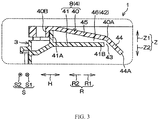
- Fig. 3 is an enlarged diagram illustrating a part represented by III in Fig. 2 .
- a right side of the paper is a radial inner side R1
- a left side of the paper is a radial outer side R2.
- the cover 40 includes a first part 44 at the radial inner side R1 and a second part 45 continuously extending from the first part 44 to the radial outer side R2.
- the inclination of the cover 40 relative to the horizontal direction H is different at a boundary of a connecting part 40A of the first part 44 and the second part 45. Inclination of the first part 44 relative to the horizontal direction H is more inclined than inclination of the second part 45 relative to the horizontal direction H.
- An outer side rib 40B protruding towards the lower side Z2 is arranged at the end part of the radial outer side R2 of the cover 40.
- An outer side rib 41A forming an arc shape protruding towards the upper side Z1 and extending along the circumferential direction S is arranged at the end part of the radial outer side R2 of the bottom part 41.
- the outer side rib 40B of the cover 40 is contacted with the outer side rib 41A of the bottom part 41 from the radial outer side R2.
- the connecting part 40A of the first part 44 and the second part 45 is opposite to the end part 41B of the radial inner side R1 of the bottom part 41 in a manner of closest to but not contact with the upper side Z1.
- An end part 44A of the radial inner side R1 of the first part 44 is positioned at a lower side Z3 of the end part 41B of the bottom part 41 and is closer to the radial inner side R1.
- the inner space 42 of the annular wall 8 includes a first space 46 closer to the radial inner side R1 than the outer side rib 41A of the bottom part 41 and formed by clamping of the second part 45 and the bottom part 41 of the cover 40 from the up-down direction Z.
- the first space 46 is in a ring shape extending along the circumferential direction S, and with inclination of the second part 45 of the cover 40, the closer to the radial inner side R1 the first space 46 is, the narrower in the up-down direction Z the first space 46 is.
- Gaps between the connecting part 40A and the first part 44 of the cover 40, and the end part 41B of the radial inner side R1 of the bottom part 41 are discharging ports 43.
- the discharging ports 43 are formed in an annular slit shape extending along the circumferential direction S. That is to say, the discharging ports 43 are arranged at the end part of the radial inner side R1 of the annular wall 8 and around the whole area of the circumferential direction S.
- the discharging ports 43 are inclined along the first part 44 of the cover 40, and face the radial inner side R1 and the lower side Z2. Due to the discharging ports 43, the first space 46 of the inner space 42 is exposed towards the radial inner side R1 and around the whole area of the circumferential direction S (referring to Fig. 2 ).
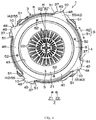
- Fig. 4 is a diagram of the washing machine 1 observed from the upper side Z1.
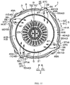
- Fig. 5 is a diagram illustrating removal of the cover 40 from the outer tank 3 in Fig. 4 .
- the cover 40 has protrusions 48 protruding towards the radial outer side R2 to form a roughly triangular shape.
- the bottom part 41 has protrusions 49 (referring to Fig. 5 ) protruding towards the radial outer side R2 to form a roughly triangular shape.
- the protrusions 48 and the protrusions 49 are respectively in a thin plate shape in the up-down direction Z, and are same with the protrusions 10 in quantity (four, herein).
- the four protrusions 48 are arranged at a roughly-equal interval at the outer circumferential part of the cover 40 and along the circumferential direction S.
- the four protrusions 49 are arranged at a roughly-equal interval at the outer circumferential part of the bottom part 41 and along the circumferential direction S.
- the bottom part 41 is provided with ribs 49A protruding towards the radial outer side R2.
- the ribs 49A are arranged at all the protrusions 49 and form a roughly V shape observed from the upper side Z1 in a mode of trimming the roughly-triangular protrusions 49 from the radial outer side R2.
- the inner space 42 of the annular wall 8 includes second spaces 55 forming hollow parts of the protrusions 10.
- the second spaces 55 of the protrusions 10 are spaces formed by clamping of the protrusions 48 and 49 from the up-down direction Z and blocked by the ribs 49A from the radial outer side R2, and are communicated with the first space 46 from the radial outer side R2.
- the inner spaces 39 of all the pipelines 37 are communicated with the second spaces 55 of the protrusions 10 by connecting parts 56 of the upper end parts 37C and the protrusions 10.
- the inner spaces 39 of the pipelines 37 are communicated with the first space 46 by the second spaces 55.
- the blades 35 of the bottom wall 21 of the washing tank 5 rotates integrally with the washing tank 5. Therefore, the blades 35 feed water stored in the outer tank 3, i.e., water stored in the gap 36 between the bottom wall 21 of the washing tank 5 and the bottom wall 7 of the outer tank 3, into the inner spaces 39 from the receiving ports 38 of all the pipelines 37.
- water stored in the gap 36 generates centrifugal force due to rotation of the blades 35 so as to be fed into the inner spaces 39 from the receiving ports 38 of the pipelines 37. Water fed into the inner spaces 39 rises in the pipelines 37 by pushing and pressing of follow-up water.
- water flowing into the first space 46 flows towards the radial inner side R1 without deviating from any area of the circumferential direction S when being diffused along the circumferential direction S. Therefore, seen from the whole circumferential direction S, water flowing from all the pipelines 37 into the first space 46 through the second spaces 55 flows towards the radial inner side R1 from the whole area of the circumferential direction S in the first space 46.
- the discharging ports 43 positioned at an end of a water flow towards the radial inner side R1 in the first space 46 are arranged around the whole area of the circumferential direction S. Therefore, water flowing from the whole area of the circumferential direction S to the radial inner side R1 in the first space 46, as shown by a dotted arrow, is discharged from the whole area of the circumferential direction S of the discharging ports 43. Water discharged from the discharging ports 43, as shown by a dotted arrow in Fig. 2 , flows into the washing tank 5 towards the inclined and lower side from the center of the washing tank 5 along inclination of the first part 44 of the cover 40.
- a great amount of water can be discharged by the discharging ports 43 arranged around the whole area of the circumferential direction S of the washing tank 5. Therefore, due to strong falling of a great amount of water discharged from the discharging ports 43 into the washing tank 5 when the washings are cleaned, detergent in the washing tank 5 can be foamed by means of water potential in the falling process of water. Thus, the washings can be cleaned effectively by means of the foamed detergent. Besides, due to strong falling of a great amount of water discharged from the discharging ports 43 into the washing tank 5, the mechanical force acting on the washings may be increased, and the cleaning capability of the washing machine can be improved. Furthermore, the washings can be rinsed efficiently by a great amount of water discharged from the upper side Z1 into the washing tank 5, so that the time of rinsing operation can be shortened.
- water absorbed from the water paths 4 and water from the discharging ports 43 can be dispersed and discharged to the central side (the radial inner side R1) and the outer circumferential side (the radial outer side R2) of the washing tank 5 by the following structure.
- the control part 33 controls the motor 30 to change the rotating speed of the washing tank 5, so that the centrifugal force generated by water in the outer tank 3 can be adjusted, and the potential of water absorbed from the water paths 4 can be adjusted.
- the larger the centrifugal force is the stronger the potential of water absorbed from the water paths 4 is
- the smaller the centrifugal force is the weaker the potential of water absorbed from the water paths 4 is.
- water with strong potential can be discharged from the discharging ports 43 to the central side of the washing tank 5, and water with weak potential can be discharged to the outer circumferential side of the washing tank 5. That is to say, water absorbed from the water paths 4 and water from the discharging ports 43 can be dispersed and discharged to the central side and the outer circumferential side of the washing tank 5 by the control part 33 of the dispersing unit 29. Thus, water can be sprinkled onto the washings in the washing tank 5 from the discharging ports 43 arranged around the circumferential direction S and the radial direction R in a manner of full range without dead angle. Thus, the washings can be cleaned or rinsed more effectively.
- Fig. 6 is a diagram illustrating the first variation example of the present invention applied in Fig. 5 .
- same reference marks are endowed for members same as the above-described members so as to omit the description, and the same mode is adopted in the following Fig. 7-Fig. 11 .
- the dispersing unit 29 includes a pair of first ribs 61 and a pair of second ribs 62 formed at the bottom part 41 of the annular wall 8 as a part of the water path 4.
- the pair of first ribs 61 and the pair of second ribs 62 are arranged in the water path 4.
- components (four groups in total, herein) formed by one pair of first ribs 61 and one pair of second ribs 62 are respectively arranged one by one.
- one pair of second ribs 62 is arranged at the position closer to the clockwise side S1 than one pair of first ribs 61.
- the first ribs 61 and the second ribs 62 protrude from the upper surface of the bottom part 41 to the upper side Z1 respectively and extend into rib shapes.
- the pair of first ribs 61 extends along the radial direction R roughly between the end parts 49B of the radial inner sides R1 of the protrusions 49 and the end part 41B of the radial inner side R1 of the bottom part 41. From the end parts 49B of the radial inner sides R1 of the protrusions 49, the closer to the end part 41B of the radial inner side R1 of the bottom part 41 the pair of second ribs 62 is, the more extension towards the clockwise side S1 the pair of second ribs 62 is.
- the protrusion 49 at the end part of the radial outer side R2 of the first rib 61 at the anticlockwise side S2 is connected with the end part of the anticlockwise side S2 of the trimming rib 49A.
- the end part of the radial outer side R2 of the second rib 62 at the clockwise side S1 is connected with the end part of the clockwise side S1 of the rib 49A.
- the part 62A of the clockwise side S1 of the second rib 62 is convexly bent towards the radial outer side R2.
- the end part of the radial outer side R2 of the first rib 61 at the clockwise side S1 in the pair of first ribs 61 is connected with the end part of the radial outer side R2 of the second rib 62 at the anticlockwise side S2 in the pair of second rib 62 at the position closer to the radial inner side R1 than the connecting part 56.
- Each first space 46 includes a space 46A formed by clamping of the pair of first ribs 61 from the circumferential direction S and a space 46B formed by clamping of the pair of second ribs 62 from the circumferential direction S.
- the spaces 46A extend towards the radial inner side R1 from the second spaces 55 along the roughly radial direction R, and from the second spaces 55, the closer to the radial inner side R1 the spaces 46B are, the more extension towards the clockwise side S1 the spaces 46B are. Therefore, a whole body of all the first spaces 46 and the second spaces 55 communicated with the first spaces 46 from the radial outer side R2 is divided into two strands in a roughly V shape from the second spaces 55 to the radial inner side R1 by observation from the upper side Z1. A distance from the second spaces 55 to the discharging ports 43 in the spaces 46A is shorter than a distance from the second spaces 55 to the discharging ports 43 in the spaces 46B.
- a moving distance of water flowing into the spaces 46A to the discharging ports 43 is shorter. Therefore, as shown by a dashed line arrow, water moving in the spaces 46A is discharged from the discharging ports 43 with almost no loss of water potential, and is sprinkled onto the washings at the central side of the washing tank 5.
- the pair of second ribs 62 are closer to the clockwise side S1 than the pair of first ribs 61, conversely, the pair of second ribs 62 may also be closer to the anticlockwise side S2 than the pair of first ribs 61.
- a flowing direction of water discharged from the discharging ports 43 can be freely adjusted by adjusting extending directions of the pair of first ribs 61 and the pair of second ribs 62.
- FIG. 7 is a diagram illustrating a second variation example of the present invention applied in Fig. 3 .
- the cover 40 of the second variation example does not have the first part 44.
- the end part 45A of the radial inner side R1 of the second part 45 of the cover 40 is closer to the radial outer side R2 than the end part 41B of the radial inner side R1 of the bottom part 41.
- the cover 40 of the second variation example is provided with a trimming part 63 formed by elastically-deformed members such as rubber and the like. The trimming part 63 is separated from the cover 40, i.e., from the water path 4, and observed from the upper side Z1, the trimming part 63 is annular.
- the inclination of the trimming part 63 relative to the horizontal direction H is consistent with that of the second part 45 relative to the horizontal direction H.
- the inclination of a part 63A closer to the radial inner side R1 than the end part 41B of the bottom part 41 relative to the horizontal direction H is steeper than that of the second part 45 relative to the horizontal direction H.
- the trimming part 63 is installed to the second part 45 of the cover 40 from the upper side Z1.
- the trimming part 63 is jointed with the end part 45A of the second part 45 by the end part of the radial outer side R2.
- the gaps between the part 63A of the radial inner side R1 of the trimming part 63 and the end part 41B of the radial inner side R1 of the bottom part 41 are used as the discharging ports 43.
- Parts of the discharging ports 43 are trimmed by the trimming part 63 from the upper side Z1.
- the end part 63B of the radial inner side R1 of the trimming part 63 is closer to the lower part Z2 and the radial inner side R1 than the bottom part 41.
- the discharging ports 43 also can be widened by bending the trimming part 63 to the upper side Z1, so that the discharging ports 43 are easy to clear.
- Fig. 8 is a diagram illustrating the third variation example of the present invention applied in Fig. 3 .
- a difference between the third variation example and the second variation example lies in arrangement of the trimming part 64 to replace the trimming part 63 in the second variation example.
- the trimming part 64 is separated from the cover 40, and is annular when being observed from the upper side Z1.
- the middle part of the trimming part 64 in the radial direction R has a step 65 bending towards the lower part Z2.
- the step 65 is contacted with the end part of the radial inner side R1 of the second part 45 from the radial inner side R1.
- the part closer to the radial inner side R1 than the step 65 is set as a first part 66
- the part closer to the radial outer side R2 than the step 65 is set as a second part 67.
- the inclination of the outer side part 66A closer to the radial outer side R2 than the end part 41B of the radial inner side R1 of the bottom part 41 relative to the horizontal direction H is consistent with that of the second part 45 relative to the horizontal direction H.
- the inclination of the inner side part 66B closer to the radial inner side R1 than the end part 41B of the radial inner side R1 of the bottom part 41 relative to the horizontal direction H is steeper than that of the second part 45 relative to the horizontal direction H.
- the inclination of the second part 67 is consistent with that of the second part 45 relative to the horizontal direction H.
- the trimming part 64 is installed to the second part 45 of the cover 40 from the upper side Z1.
- the trimming part 64 is jointed with the cover 40 by the step 65 and the second part 67.
- the gaps between the inner side part 66B of the first part 66 of the trimming part 64 and the end part 41B of the radial inner side R1 of the bottom part 41 are used as the discharging ports 43.
- Parts of the discharging ports 43 are trimmed by the trimming part 64 from the upper side Z1.
- the end part 66C of the radial inner side R1 of the inner side part 66B of the first part 66 is positioned at the lower part Z2 of the bottom part 41 and is closer to the radial inner side R1.
- the third variation example is similar. Under a condition that the discharging ports 43 are blocked by dirt and the like, even though the water paths 4 are not split, as shown by the double-dot line in Fig. 8 , the discharging ports 43 also can be widened by bending the whole first part 66 of the trimming part 64 to the upper side Z1, so that the discharging ports 43 are easy to clear.
- Fig. 9 is a diagram illustrating the fourth variation example of the present invention applied in Fig. 2 .
- the enclose 2 includes a door 71 and an upper panel 72 at an upper end part.
- An opening 74 is formed in an upper surface of the enclosure 2.
- the access 25 is positioned at the lower part Z2 of the opening 74.
- the door 71 blocks the opening 74 of a main body 70 from the upper side Z1.
- the upper panel 72 is fixed at the part of a rear side Y2 of the opening 74 at the upper end part of the enclosure 2 so as to support the rear end of the door 71.
- the user of the washing machine 1 can open the door 71 from a front side Y1 of the washing machine 1.
- the user of the washing machine 1 can put the washings into the washing tank 5 or take the washings out of the washing tank 5 from the upper side Z1 through the access 25 under a condition that the door 71 is opened. Since the door 71 is transparent or semitransparent, the user can determine the condition in the washing tank 5 through the closed door 71 by visual inspection.
- the side wall 6 of the outer tank 3 is made of semitransparent resin.
- the whole outer tank 3 also can be semitransparent.
- a water discharging port not shown in the drawings and used for discharging water in the outer tank 3 is formed in the bottom wall 7 of the outer tank 3.
- a water discharging path 76 for discharging water out of the washing machine 1 is connected at water discharging port.
- the water discharging path 76 is provided with a dirt sensor 77 for detecting the dirty degree of water discharging out of the washing machine 1.
- a known structure can be used as the dirt sensor 77.
- the dirt sensor 77 is electrically connected with the control part 33. A detection result of the dirt sensor 77 is input into the control part 33.
- the washing machine 1 includes a light source 81.
- the light source 81 includes one or more LEDs for exampel and can emit lights with various colors.
- the light source 81 is electrically connected with the control part 33 which can control a light emitting mode of the light source 81.
- the light source 81 is installed, for example, on the outer circumferential surface 6A of the side wall 6 of the outer tank 3 from the rear side Y2. Light emitted from the light source 81 irradiates to water in the washing tank 5 from the rear side Y2. Specifically, the light emitted from the light source 81 permeates through the semitransparent side wall 6 of the outer tank 3 and irradiates to water in the washing tank 5 from the rear side Y2 by penetrating through the through holes 23 of the side wall 20 of the washing tank 5.
- Another light source 82 also can be arranged for replacing the light source 81.
- the light source 82 is compoesd of, for example, one or more LEDs, and can emit lights with various colors.
- the light source 82 is electrically connected with the control part 33.
- the control part 33 can control the light emitting mode of the light source 82.
- the light source 82 is installed, for example, on a lower surface of the upper panel 72 from the lower part Z2. The light emitted from the light source 82 irradiates to water in the washing tank 5 from the upper side Z1 or to water discharged from the discharging ports 43 into the washing tank 5.
- Other light sources 83 also can be arranged for replacing the light source 81.
- a plurality of light sources 83 are arranged.
- Each light source 83 is composed of, for example, one or more LEDs, and can emit lights with various colors.
- the light sources 83 are electrically connected with the control part 33 which can control the light emitting mode of the light sources 83.
- the outer tank 3 includes a supporting member 73 which is annular by observation from the upper side Z1.
- the supporting member 73 is installed on the cover 40 of the annular wall 8 from the upper side Z1.
- the plurality of light sources 83 are installed, for example, on the upper surface of the supporting member 73 from the upper side Z1, and are configured in parallel along the circumferential direction S.
- the plurality of light sources 83 also can be installed on a lower surface of the supporting member 73 from the lower side Z2.
- the lights emitted from the light sources 83 irradiate to water in the washing tank 5 or water discharged from the discharging ports 43 into the washing tank 5 from the upper side Z1.
- the light sources 81, 82 and 83 not only can be separately arranged, but also can be combined. Water in the washing tank 5 or water discharged from the discharging ports 43 into the washing tank 5 has a color of the lights emitted from the above light sources 81, 82 and 83.
- the light sources 81, 82 and 83 are lighted, or the colors of the lights emitted from the light sources 81, 82 and 83 are changed. Therefore, the operating state of the washing machine 1 can be transferred to the user in a visual mode.
- the dirty degree of water also can be detected according to the dirt sensor 77 during rinsing operation, and the colors of the lights emitted from the light source 81, 82 or 83 are changed. For example, under a condition that dirty degree of the discharged water is high, all the light sources 81, 82 and 83 emit red lights. When the dirty degree of the discharged water is reduced, the colors of the lights become yellow from red. When the dirty degree of the discharged water is further reduced, the colors of the lights become blue from yellow. Thus, the rinsing state of the washings can be transferred to the user of the washing machine 1 in a visual mode.
- Fig. 10 is a diagram illustrating the fifth variation example of the present invention applied in Fig. 2 .
- the washing machine 1 includes a water pumping wing 84 separated from the washing tank 5.
- the water pumping wing 84 can rotate relative to the washing tank 5 along the circumferential direction S.
- the plurality of blades 35 are not formed on the washing tank 5.
- the water pumping wing 84 is round, and the plurality of above-mentioned blades 35 are formed at the upper surface of the water pumping wing 84.
- the water pumping wing 84 is configured in the gap 36.
- the washing machine 1 of the fifth variation example includes a first transmission shaft 85 and a second transmission shaft 86 to replace the transmission shaft 31 in the present implementation mode.
- the first transmission shaft 85 extends towards the upper side Z1.
- the second transmission shaft 86 is cylindrical and extends towards the upper side Z1, and contains the first transmission shaft 85.
- the first transmission shaft 85 and the second transmission shaft 86 are coaxially configured in a state without contacting each other.
- the first transmission shaft 85 and the second transmission shaft 86 are coaxially configured with the output shaft 34 at the upper side Z1 of the output shaft 34.
- the output shaft 34 is connected with the first transmission shaft 85 via the transmission mechanism 32.
- the output shaft 34 is connected with the second transmission shaft 86 via the transmission mechanism 32.
- the first transmission shaft 85 penetrates the circle center part of the bottom wall 7 of the outer tank 3 and extends towards the upper side Z1. An upper end part of the first transmission shaft 85 is connected with the circle center part of the bottom wall 21 of the washing tank 5.
- the second transmission shaft 86 extends to the gap 36 of the up-down direction Z between the bottom wall 21 and the bottom wall 7 of the outer tank 3. An upper end part of the second transmission shaft 86 is connected with the circle center part of the water pumping wing 84.
- Torque generated by the motor 30 is respectively transmitted to the first transmission shaft 85 and the second transmission shaft 86 via the output shaft 34 and the transmission mechanism 32.
- the washing tank 5 adopts the first transmission shaft 85 as the center of rotation and rotates together with the first transmission shaft 85.
- the water pumping wing 84 adopts the second transmission shaft 86 as the center of rotation, and rotates together with the second transmission shaft 86. Therefore, in the washing machine 1 of the fifth variation example, the plurality of blades 35 of the water pumping wing 84 and the washing tank 5 can separately rotate respectively.
- a load of the motor 30 can be reduced by making the water pumping wing 84 rotate only. Therefore, the temperature rise of the motor 30 can be prevented.
- the washing tank 5 also can rotate together with the water pumping wing 84. In this way, since the positions of the washings in the washing tank 5 can be changed, water can be sprinkled onto the washings without dead angle. Under this condition, the rotating direction of the washing tank 5 and the rotating direction of the water pumping wing 84 also can be reversed.
- Fig. 11 is a diagram illustrating a sixth variation example of the present invention applied in Fig. 5 .
- the bottom part 41 of the annular wall 8 as a part of the water path 4 includes ribs 87.
- the ribs 87 are arranged at all the protrusions 49 in a one-by-one manner.
- the flowing of water flowing into the first space 46 is shown by the solid arrow, and faces the clockwise side S1 by means of the ribs 87.
- a direction of water discharged from the discharging ports 43 can be adjusted by an extending direction of the ribs 87, so that under a condition that the rotating direction of the washing tank 5 is the clockwise side S1, the direction of water discharged from the discharging ports 43 can be consistent with the rotating direction of the washing tank 5.
- the present invention is not limited to the contents of the above implementation modes, and can be changed within a scope recorded in claims.
- the first variation example to the sixth variation example also can be randomly combined and applied into the present implementation mode.
- the bottom wall 21 of the washing tank 5 is not fully made of resin; and the part connected with the transmission shaft 31 also can be made of metal.
Landscapes
- Engineering & Computer Science (AREA)
- Textile Engineering (AREA)
- Main Body Construction Of Washing Machines And Laundry Dryers (AREA)
- Detail Structures Of Washing Machines And Dryers (AREA)
Abstract
Description
- The present invention relates to a washing machine.
- The washing machine in the following
patent literature 1 has an impeller arranged at a bottom of the washing tank and one or more circulating water paths arranged at a side wall of the washing tank. A back blade is arranged on a back surface of the impeller. - When the back blade of the impeller rotates, washing water from the back surface of the impeller passes through the circulating water path, is discharged into the washing tank from the discharging ports at an upper end of the circulating water path and is sprinkled onto clothes in the washing tank.
- In the washing machine of the
patent literature 1, under a condition that only one circulating water path is arranged, the discharging port only exists at one circumferential position of the washing tank. Under a condition that a plurality of circulating water paths are arranged, a plurality of discharging ports are configured at intervals in the circumferential direction of the washing tank. Therefore, the washing water discharged from all the discharging ports only can reach limited positions in the circumferential direction in the washing tank. In this way, the washing water is hard to wholly sprinkle onto the clothes in the washing tank. - The present invention is completed on the basis of the background and aims at providing a washing machine capable of sprinkling water on washings contained in a washing tank without dead angle.
- The present invention provides a washing machine, including an outer tank capable of storing water, a cylindrical washing tank contained in the outer tank, having through holes for allowing water to flow between the washing tank and the outer tank, used for containing the washings and capable of rotating, and a water path for absorbing water stored in the outer tank and discharging water into the washing tank from the upper side. Discharging ports for discharging water into the washing tank from the upper side through the water path are arranged around the whole area of the circumferential direction of the washing tank.
- In addition, the present invention includes trimming parts for trimming local parts of the discharging ports. The trimming parts are separated from the water path.
- In addition, the present invention includes a cover forming the outer tank. The cover is also used as at least one part of the water path.
- In addition, the present invention includes a dispersing unit. The dispersing unit is used for dispersing and discharging water absorbed from the water path to a central side and an outer circumferential side of the washing tank from the discharging ports.
- In addition, in the present invention, the dispersing unit includes ribs. The ribs are arranged in the water path and are used for distributing water from the discharging ports to the central side and the outer circumferential side of the washing tank.
- In addition, in the present invention, the dispersing unit includes a changing unit for changing a rotating speed of the washing tank.
- In addition, the present invention includes light sources lighted according to an operating state of the washing machine.
- According to the present invention, in the washing machine, the washing tank for containing washings is rotatably contained in the outer tank. Water in the outer tank generates centrifugal force and the like with the rotation of the washing tank. Therefore, the water path absorbs water stored in the outer tank. The discharging ports on the water path discharge water absorbed from the upper side into the washing tank. Water in the washing tank can flow between the washing tank and the outer tank through the through holes of the washing tank. Therefore, water can be used for washing while circulating, so that water can be saved.
- Since the discharging ports are arranged around the whole area of the circumferential direction of the cylindrical washing tank, water can be discharged into the washing tank from the whole area of the circumferential direction of the washing tank. Therefore, water can be sprinkled on the washings contained in the washing tank without dead angle from the whole area of the circumferential direction of the washing tank..
- In addition, a great amount of water can be discharged by the discharging ports arranged around the whole area of the circumferential direction of the washing tank. Thus, when the washings are cleaned, due to strong falling of a great amount of water discharged from the discharging ports into the washing tank, a water potential in a falling process of water can be used for foaming detergent in the washing tank. Therefore, the washings can be cleaned effectively by the foamed detergent. Furthermore, due to strong falling of a great amount of water discharged from the discharging ports into the washing tank, the mechanical force acting on the washings is increased, and the cleaning capability of the washing machine can be improved. Besides, since the washings can be rinsed efficiently by a great amount of water discharged from the upper side into the washing tank, the time of rinsing operation can be shortened.
- In addition, according to the present invention, the local parts of the discharging ports are trimmed by the trimming parts separated from the water path. Therefore, under a condition of blockage of the discharging ports due to dirt and the like, even though the water path is not split, the discharging ports can be widened by bending the trimming parts, thereby realizing easy cleaning for the discharging ports.
- In addition, according to the present invention, since the cover forming the outer tank is also used as one part of the water path, the quantity of parts can be reduced.
- In addition, according to the present invention, the dispersing unit disperses and discharges water absorbed from the water path to the central side and the outer circumferential side of the washing tank. Therefore, water can be further sprinkled onto the washings in the washing tank from the discharging ports without dead angle. Thus, the washings can be cleaned or rinsed more effectively.
- In addition, according to the present invention, the dispersing unit also can be ribs arranged in the water path.
- In addition, according to the present invention, the centrifugal force generated by water in the outer tank can be adjusted by utilizing the changing unit to change the rotating speed of the washing tank. Thus, the potential of water absorbed from the water path can be adjusted. Therefore, water with strong potential can be discharged to the central side of the washing tank from the discharging ports or water with weak potential can be discharged to the outer circumferential side from the discharging ports.
- In addition, according to the present invention, the light sources are lighted according to the operating state of the washing machine. Therefore, the operating state of the washing machine can be visually transferred to a user.
-
-
Fig. 1 is a stereoscopic diagram illustrating an internal structure of awashing machine 1 of one embodiment observed from an upper side in the present invention; -
Fig. 2 is a vertical section view illustrating an internal structure of thewashing machine 1; -
Fig. 3 is an enlarged diagram of a part represented by III inFig. 2 ; -
Fig. 4 is a diagram illustrating thewashing machine 1 observed from an upper side; -
Fig. 5 is a diagram illustrating removal of a cover from an outer tank in thewashing machine 1 ofFig. 4 ; -
Fig. 6 is a diagram illustrating a first variation example of the present invention applied inFig. 5 ; -
Fig. 7 is a diagram illustrating a second variation example of the present invention applied inFig. 3 ; -
Fig. 8 is a diagram illustrating a third variation example of the present invention applied inFig. 3 ; -
Fig. 9 is a diagram illustrating a fourth variation example of the present invention applied inFig. 2 ; -
Fig. 10 is a diagram illustrating a fifth variation example of the present invention applied inFig. 2 ; -
Fig. 11 is a diagram illustrating a sixth variation example of the present invention applied inFig. 5 . - 1: washing machine; 3: outer tank; 4: water path; 5: washing tank; 23: through hole; 29: dispersing unit; 33: control part; 40: cover; 43: discharging port; 61: first rib; 62: second rib; 63: trimming part; 64: trimming part; 81: light source; 82: light source; 83: light source; S: circumferential direction; Z1: upper side.
- An implementation mode of the present invention is described in detail below with reference to drawings.
Fig. 1 is a stereoscopic diagram illustrating an internal structure of awashing machine 1 of one embodiment observed from an upper side in the present invention. - It should be noted that a gesture of the
washing machine 1 inFig. 1 prevails under a condition of mentioning directions of thewashing machine 1. An up-down direction inFig. 1 is consistent with an up-down direction Z (vertical) of thewashing machine 1. In the up-down direction Z, an upper side is called as an upper side Z1 and a lower side is called as a lower side Z2. A left-right direction inFig. 1 is consistent with a left-right direction X of thewashing machine 1. In the left-right direction X, a left side is called as a left side X1 and a right side is called as a right side X2. A direction orthogonal to the up-down direction Z and the left-right direction X is a front-rear direction Y of thewashing machine 1. In the front-rear direction Y, a front side is called as a front side Y1 and a rear side is called as a rear side Y2. The left-right direction X and the front-rear direction Y are included in a horizontal direction H (transverse). - Referring to
Fig. 1 , thewashing machine 1 includes anenclosure 2, anouter tank 3 and awashing tank 5. Theenclosure 2 is a hollow body in a roughly cuboid shape, and theouter tank 3 and thewashing tank 5 are contained in theenclosure 2. - The
outer tank 3 is supported by theenclosure 2 through a plurality of hanger rods (not shown in the drawings) with springs and damping mechanisms. Theouter tank 3 is formed in a cylindrical shape having an axis extending along the up-down direction Z, and is made from resin. A circumferential direction of the cylindricalouter tank 3 is called as a circumferential direction S. In the circumferential direction S, a clockwise side observed from the upper side Z1 is called as a clockwise side S1, and an anticlockwise side observed from the upper side Z1 is called as an anticlockwise side S2. A radial direction of theouter tank 3 is called as a radial direction R. In the radial direction R, an inner side close to the axis of theouter tank 3 is called as a radial inner side R1, and an outer side far away from the axis is called as a radial outer side R2. - The
outer tank 3 has acylindrical side wall 6 extending along the up-down direction Z, a disc-shapedbottom wall 7 extending flatly along the horizontal direction H and blocking a lower end of theside wall 6, and a hollowannular wall 8 protruding from an upper end part of theside wall 6 to the radial inner side R1 around the whole area of the circumferential direction S. The outercircumferential surface 6A of theside wall 6 is an outer side surface of theouter tank 3. In theouter tank 3, water is stored from the side of thebottom wall 7. - A
round opening 9 divided by the inner circumferential edge of theannular wall 8 is formed at an upper end of theouter tank 3. Due to theopening 9, the inner part of theouter tank 3 is exposed to the upper side Z1. Theannular wall 8 has a plurality of (four herein)protrusions 10. The plurality ofprotrusions 10 are arranged at intervals in the circumferential direction S. Observed from the upper side Z1, the protrusions form a roughly triangular shape from an outer circumferential part of theannular wall 8 to the radial outer side R2. Theprotrusions 10 are respectively configured at four corners of theenclosure 2 forming a roughly quadrangular shape when being viewed from the upper side. All theprotrusions 10 are hollow. - The
washing tank 5 is formed in a cylindrical shape with an axis extending along the up-down direction Z, and is slightly smaller than theouter tank 3. The washings are contained in thewashing tank 5. Thewashing tank 5 has acylindrical side wall 20 made of metal and extending along the up-down direction Z, a disc-shapedbottom wall 21 made of resin and flatly extending along the horizontal direction H and blocking the lower end of theside wall 20, and abalancing ring 22 made of resin and arranged at the upper end of thewashing tank 5. A plurality of throughholes 23 are respectively formed in theside wall 20 and thebottom wall 21. - The balancing
ring 22 is an annular hollow body having an inner space for containing liquid and is arranged coaxially to the upper end part of theside wall 20. When thewashing tank 5 rotates like the after-mentioned content, the balance of rotation of thewashing tank 5 is maintained by movement of the liquid in the balancingring 22. Around opening 24 divided by the inner circumferential edge of the balancingring 22 is formed at the upper end of thewashing tank 5. Due to theopening 24, the inner part of thewashing tank 5 is exposed to the upper side Z1. - The
washing tank 5 is contained in theouter tank 3, and is roughly coaxial to theouter tank 3. Therefore, the circumferential direction of thewashing tank 5 is the above-mentioned circumferential direction S, and the radial direction of thewashing tank 5 is the above-mentioned radial direction R. The radial inner side R1 is a direction towards the central axis of thewashing tank 5, and the radial outer side R2 is a direction far away from the axis of thewashing tank 5 and towards theside wall 20 of the outer circumferential side. Theopening 24 of thewashing tank 5 is communicated with theopening 9 of theouter tank 3 from the lower side Z2. Theopenings access 25 of the washings. A user of thewashing machine 1 puts the washings into thewashing tank 5 or takes the washings out of thewashing tank 5 through theaccess 25 from the upper side Z1. In thewashing tank 5 contained in theouter tank 3, thebottom wall 21 is opposite to thebottom wall 7 of theouter tank 3 from the upper side Z across a gap. - Water stored in the
outer tank 3 flows between theouter tank 3 and thewashing tank 5 through the through holes in theside wall 20 and thebottom wall 21 of thewashing tank 5. Therefore, a water level in theouter tank 3 is roughly consistent to that in thewashing tank 5. -
Fig. 2 is a longitudinal section view illustrating an internal structure of thewashing machine 1. Specifically,Fig. 2 is a view of the section when a roughly central part of the left-right direction X of thewashing machine 1 observed from the right part X2 is sectioned along the front-rear direction Y. - Referring to
Fig. 2 , thewashing machine 1 includes amotor 30, atransmission shaft 31, atransmission mechanism 32 formed by a speed reducing mechanism and the like, and a dispersingunit 29. - The
motor 30 is electrically driven to generate torque. Themotor 30 is arranged in theenclosure 2 and configured at the lower side Z2 of thebottom wall 7 of theouter tank 3. Themotor 30 is provided with anoutput shaft 34 for outputting torque. Theoutput shaft 34 extends from themotor 30 to the upper side Z1. - The
transmission shaft 31 penetrates through the circle center part of thebottom wall 7 of theouter tank 3 and extends towards the upper side Z1. Thetransmission shaft 31 is coaxially arranged with theoutput shaft 34 at the upper side Z1 of theoutput shaft 34. Theoutput shaft 34 and thetransmission shaft 31 are connected by thetransmission mechanism 32. - The upper end part of the
transmission shaft 31 is connected with the circle center part of thebottom wall 21 of thewashing tank 5. Torque generated by themotor 30 is transmitted to thetransmission shaft 31 via theoutput shaft 34 and thetransmission mechanism 32. Therefore, thewashing tank 5 rotates together with thetransmission shaft 31 by adopting thetransmission shaft 31 as a center of rotation. A rotating direction of thewashing tank 5 is consistent with the circumferential direction S. - The dispersing
unit 29 is a member for dispersing water to the central side and the outer circumferential side of thewashing tank 5 and includes acontrol part 33 as a changing unit. Thecontrol part 33 is a microcomputer including CPU, ROM, RAM and the like, for example, and is configured in the enclosure 2 (referring toFig. 1 ). Thecontrol part 33 is connected with themotor 30 by a signal circuit not shown in the drawings. Thecontrol part 33 can change the rotating speed of thewashing tank 5 by controlling torque generated by themotor 30. - Under a state that detergent is dissolved in water stored in the
outer tank 3, the washing operation for the washings contained in thewashing tank 5 is executed by rotation of thewashing tank 5. After the washing operation, under a state that theouter tank 3 supplies water, the rinsing operation for the washings contained in thewashing tank 5 is executed by rotation of thewashing tank 5. Under a state of drainage from theouter tank 3, the dewatering operation for the washings contained in thewashing tank 5 is executed by high-speed rotation of thewashing tank 5. - A plurality of
blades 35 protruding towards the lower side Z2 are integrally arranged on thelower surface 21A of thebottom wall 21 of thewashing tank 5. All theblades 35 form a plate shape linearly extending along the thin radial direction R in the circumferential direction S, and are radially configured by adopting the circle center of thebottom wall 21 as a reference. Theblades 35 are configured in agap 36 in the up-down direction Z between thebottom wall 21 and thebottom wall 7 of theouter groove 3 under a state of non-contacting with theouter tank 3. - The
washing machine 1 includes awater path 4 contained in theenclosure 2. Thewater path 4 includes thin andlong pipelines 37 made of resin. A plurality ofpipelines 37 are arranged on the outercircumferential surface 6A of theside wall 6 in such a manner that quantity ofpipelines 37 are same (four herein) as that of the above-mentioned protrusions 10 (referring toFig. 1 ). Thepipelines 37 havelower end parts 37A extending out along the horizontal direction H from the lower end part of theside wall 6 of theouter tank 3 to the radial outer side R2,middle parts 37B bending from thelower end parts 37A and extending along the outercircumferential surface 6A towards the upper side Z1, andupper end parts 37C (referring toFig. 1 ) extending from themiddle parts 37B to the upper side X and connected with theprotrusions 10 from the lower side Z2. Themiddle parts 37B also may not need to extend linearly along the up-down direction Z, but extend towards the upper side Z1 while bending or folding as needed. - Like the
protrusions 10, thepipelines 37 are respectively arranged at the four corners (referring toFig. 1 ) of theenclosure 2. All thepipelines 37 have receivingports 38 at the connecting parts between thelower end parts 37A and theside wall 6 of theouter tank 3, and theinner spaces 39 of thepipelines 37 are communicated with the inner part of theouter tank 3 through the receivingports 38, specifically, communicated with the above-mentionedgap 36. - Besides the
pipelines 37, thewater path 4 further includes anannular wall 8 of theouter tank 3 as a component of thewater path 4. Theannular wall 8 includes acover 40 and abottom part 41. Thecover 40 and thebottom part 41 form a ring shape extending along the circumferential direction S respectively. Thecover 40 is in a thin plate shape in the up-down direction Z, and the closer to the radial inner side R1 the more inclination towards the lower side Z2 relative to the horizontal direction H. Thebottom part 41 is in a thin plate in the up-down direction Z, and is configured along the horizontal direction H. Thebottom part 41 is integrated with the upper end part of theside wall 6 of theouter tank 3. Therefore, since thecover 40 and thebottom part 41 forming theannular wall 8 of theouter tank 3 are used as part of thewater path 4, the quantity of the parts can be reduced. - The
cover 40 coaxially covers thebottom part 41 from the upper side Z1. Aninner space 42 is formed between thecover 40 and thebottom part 41, theinner space 42 is a hollow part of theannular wall 8 and forms a ring shape extending along the circumferential direction S. -
Fig. 3 is an enlarged diagram illustrating a part represented by III inFig. 2 . InFig. 3 , a right side of the paper is a radial inner side R1, and a left side of the paper is a radial outer side R2. - Referring to
Fig. 3 , thecover 40 includes afirst part 44 at the radial inner side R1 and asecond part 45 continuously extending from thefirst part 44 to the radial outer side R2. The inclination of thecover 40 relative to the horizontal direction H is different at a boundary of a connectingpart 40A of thefirst part 44 and thesecond part 45. Inclination of thefirst part 44 relative to the horizontal direction H is more inclined than inclination of thesecond part 45 relative to the horizontal direction H. Anouter side rib 40B protruding towards the lower side Z2 is arranged at the end part of the radial outer side R2 of thecover 40. Anouter side rib 41A forming an arc shape protruding towards the upper side Z1 and extending along the circumferential direction S is arranged at the end part of the radial outer side R2 of thebottom part 41. - The
outer side rib 40B of thecover 40 is contacted with theouter side rib 41A of thebottom part 41 from the radial outer side R2. In thecover 40, the connectingpart 40A of thefirst part 44 and thesecond part 45 is opposite to theend part 41B of the radial inner side R1 of thebottom part 41 in a manner of closest to but not contact with the upper side Z1. Anend part 44A of the radial inner side R1 of thefirst part 44 is positioned at a lower side Z3 of theend part 41B of thebottom part 41 and is closer to the radial inner side R1. - The
inner space 42 of theannular wall 8 includes afirst space 46 closer to the radial inner side R1 than theouter side rib 41A of thebottom part 41 and formed by clamping of thesecond part 45 and thebottom part 41 of thecover 40 from the up-down direction Z. Thefirst space 46 is in a ring shape extending along the circumferential direction S, and with inclination of thesecond part 45 of thecover 40, the closer to the radial inner side R1 thefirst space 46 is, the narrower in the up-down direction Z thefirst space 46 is. - Gaps between the connecting
part 40A and thefirst part 44 of thecover 40, and theend part 41B of the radial inner side R1 of thebottom part 41 are dischargingports 43. The dischargingports 43 are formed in an annular slit shape extending along the circumferential direction S. That is to say, the dischargingports 43 are arranged at the end part of the radial inner side R1 of theannular wall 8 and around the whole area of the circumferential direction S. The dischargingports 43 are inclined along thefirst part 44 of thecover 40, and face the radial inner side R1 and the lower side Z2. Due to the dischargingports 43, thefirst space 46 of theinner space 42 is exposed towards the radial inner side R1 and around the whole area of the circumferential direction S (referring toFig. 2 ). -
Fig. 4 is a diagram of thewashing machine 1 observed from the upper side Z1.Fig. 5 is a diagram illustrating removal of thecover 40 from theouter tank 3 inFig. 4 . - Referring to
Fig. 4 , thecover 40 hasprotrusions 48 protruding towards the radial outer side R2 to form a roughly triangular shape. Thebottom part 41 has protrusions 49 (referring toFig. 5 ) protruding towards the radial outer side R2 to form a roughly triangular shape. Theprotrusions 48 and theprotrusions 49 are respectively in a thin plate shape in the up-down direction Z, and are same with theprotrusions 10 in quantity (four, herein). The fourprotrusions 48 are arranged at a roughly-equal interval at the outer circumferential part of thecover 40 and along the circumferential direction S. The fourprotrusions 49 are arranged at a roughly-equal interval at the outer circumferential part of thebottom part 41 and along the circumferential direction S. - Referring to
Fig. 5 , as a part of theouter side rib 41A, thebottom part 41 is provided withribs 49A protruding towards the radial outer side R2. Theribs 49A are arranged at all theprotrusions 49 and form a roughly V shape observed from the upper side Z1 in a mode of trimming the roughly-triangular protrusions 49 from the radial outer side R2. - Referring to
Fig. 4 , in thecover 40 arranged at thebottom part 41, all theprotrusions 48 are respectively overlapped with theprotrusions 49 of thebottom part 41 from the upper side Z1. Theprotrusions screws 51 installed at all the outer edge parts so as to form the above-mentionedprotrusions 10. Thecover 40 and thebottom part 41 are also connected by means ofscrews 52 installed at the positions staggered from theprotrusions 10 in the circumferential direction S. - The
inner space 42 of theannular wall 8 includessecond spaces 55 forming hollow parts of theprotrusions 10. Referring toFig. 5 , thesecond spaces 55 of theprotrusions 10 are spaces formed by clamping of theprotrusions ribs 49A from the radial outer side R2, and are communicated with thefirst space 46 from the radial outer side R2. - The
inner spaces 39 of all thepipelines 37 are communicated with thesecond spaces 55 of theprotrusions 10 by connectingparts 56 of theupper end parts 37C and theprotrusions 10. Theinner spaces 39 of thepipelines 37 are communicated with thefirst space 46 by thesecond spaces 55. - Referring to
Fig. 2 , when thewashing tank 5 receives torque of themotor 30 to rotate, theblades 35 of thebottom wall 21 of thewashing tank 5 rotates integrally with thewashing tank 5. Therefore, theblades 35 feed water stored in theouter tank 3, i.e., water stored in thegap 36 between thebottom wall 21 of thewashing tank 5 and thebottom wall 7 of theouter tank 3, into theinner spaces 39 from the receivingports 38 of all thepipelines 37. In addition, water stored in thegap 36 generates centrifugal force due to rotation of theblades 35 so as to be fed into theinner spaces 39 from the receivingports 38 of thepipelines 37. Water fed into theinner spaces 39 rises in thepipelines 37 by pushing and pressing of follow-up water. - Referring to
Fig. 5 , water rising to theupper end parts 37C of all thepipelines 37 flows into thesecond spaces 55 corresponding to theinner space 42 of theannular wall 8. Water flowing into all thesecond spaces 55 is guided by theribs 49A, as shown by a solid arrow, and flows into thefirst space 46 when being radially diffused from the connectingparts 56 to the radial inner side R1. - As mentioned above, the closer to the radial inner side R1 the
first space 46 is, the narrower in the up-down direction Z thefirst space 46 is (referring toFig. 3 ). Thus, water flowing into thefirst space 46 flows towards the radial inner side R1 without deviating from any area of the circumferential direction S when being diffused along the circumferential direction S. Therefore, seen from the whole circumferential direction S, water flowing from all thepipelines 37 into thefirst space 46 through thesecond spaces 55 flows towards the radial inner side R1 from the whole area of the circumferential direction S in thefirst space 46. - As mentioned above, the discharging
ports 43 positioned at an end of a water flow towards the radial inner side R1 in thefirst space 46 are arranged around the whole area of the circumferential direction S. Therefore, water flowing from the whole area of the circumferential direction S to the radial inner side R1 in thefirst space 46, as shown by a dotted arrow, is discharged from the whole area of the circumferential direction S of the dischargingports 43. Water discharged from the dischargingports 43, as shown by a dotted arrow inFig. 2 , flows into thewashing tank 5 towards the inclined and lower side from the center of thewashing tank 5 along inclination of thefirst part 44 of thecover 40. - In this way, water stored in the
outer tank 3 is absorbed by thewater paths 4, and water absorbed by thewater paths 4 is discharged into thewashing tank 5 from the upper side Z1 by the dischargingports 43 of thewater paths 4. Water in thewashing tank 5 flows between thewashing tank 5 and theouter tank 3 through the throughholes 23 of thewashing tank 5. - Therefore, since water also can be used for washing while in circulation, water can be saved. As mentioned above, since the discharging
ports 43 are arranged in the whole area of the circumferential direction S of thecylindrical washing tank 5, water can be discharged into thewashing tank 5 from the whole area of the circumferential direction S of thewashing tank 5. Thus, water can be sprinkled onto the washings contained in thewashing tank 5 from the whole area of the circumferential direction S of thewashing tank 5 without dead angle. - In addition, a great amount of water can be discharged by the discharging
ports 43 arranged around the whole area of the circumferential direction S of thewashing tank 5. Therefore, due to strong falling of a great amount of water discharged from the dischargingports 43 into thewashing tank 5 when the washings are cleaned, detergent in thewashing tank 5 can be foamed by means of water potential in the falling process of water. Thus, the washings can be cleaned effectively by means of the foamed detergent. Besides, due to strong falling of a great amount of water discharged from the dischargingports 43 into thewashing tank 5, the mechanical force acting on the washings may be increased, and the cleaning capability of the washing machine can be improved. Furthermore, the washings can be rinsed efficiently by a great amount of water discharged from the upper side Z1 into thewashing tank 5, so that the time of rinsing operation can be shortened. - Moreover, water absorbed from the
water paths 4 and water from the dischargingports 43 can be dispersed and discharged to the central side (the radial inner side R1) and the outer circumferential side (the radial outer side R2) of thewashing tank 5 by the following structure. For example, the control part 33 (referring toFig. 2 ) controls themotor 30 to change the rotating speed of thewashing tank 5, so that the centrifugal force generated by water in theouter tank 3 can be adjusted, and the potential of water absorbed from thewater paths 4 can be adjusted. Specifically, the larger the centrifugal force is, the stronger the potential of water absorbed from thewater paths 4 is, and the smaller the centrifugal force is, the weaker the potential of water absorbed from thewater paths 4 is. Therefore, water with strong potential can be discharged from the dischargingports 43 to the central side of thewashing tank 5, and water with weak potential can be discharged to the outer circumferential side of thewashing tank 5. That is to say, water absorbed from thewater paths 4 and water from the dischargingports 43 can be dispersed and discharged to the central side and the outer circumferential side of thewashing tank 5 by thecontrol part 33 of the dispersingunit 29. Thus, water can be sprinkled onto the washings in thewashing tank 5 from the dischargingports 43 arranged around the circumferential direction S and the radial direction R in a manner of full range without dead angle. Thus, the washings can be cleaned or rinsed more effectively. - Next, a first variation example about the present invention will be described.
-
Fig. 6 is a diagram illustrating the first variation example of the present invention applied inFig. 5 . InFig. 6 , same reference marks are endowed for members same as the above-described members so as to omit the description, and the same mode is adopted in the followingFig. 7-Fig. 11 . - Referring to
Fig. 6 , in the first variation example, the dispersingunit 29 includes a pair offirst ribs 61 and a pair ofsecond ribs 62 formed at thebottom part 41 of theannular wall 8 as a part of thewater path 4. The pair offirst ribs 61 and the pair ofsecond ribs 62 are arranged in thewater path 4. Corresponding to all theprotrusions 49, components (four groups in total, herein) formed by one pair offirst ribs 61 and one pair ofsecond ribs 62 are respectively arranged one by one. In all the components, one pair ofsecond ribs 62 is arranged at the position closer to the clockwise side S1 than one pair offirst ribs 61. Thefirst ribs 61 and thesecond ribs 62 protrude from the upper surface of thebottom part 41 to the upper side Z1 respectively and extend into rib shapes. - The pair of
first ribs 61 extends along the radial direction R roughly between theend parts 49B of the radial inner sides R1 of theprotrusions 49 and theend part 41B of the radial inner side R1 of thebottom part 41. From theend parts 49B of the radial inner sides R1 of theprotrusions 49, the closer to theend part 41B of the radial inner side R1 of thebottom part 41 the pair ofsecond ribs 62 is, the more extension towards the clockwise side S1 the pair ofsecond ribs 62 is. - In the pair of
first ribs 61, theprotrusion 49 at the end part of the radial outer side R2 of thefirst rib 61 at the anticlockwise side S2 is connected with the end part of the anticlockwise side S2 of the trimmingrib 49A. In the pair ofsecond ribs 62, the end part of the radial outer side R2 of thesecond rib 62 at the clockwise side S1 is connected with the end part of the clockwise side S1 of therib 49A. Thepart 62A of the clockwise side S1 of thesecond rib 62 is convexly bent towards the radial outer side R2. - The end part of the radial outer side R2 of the
first rib 61 at the clockwise side S1 in the pair offirst ribs 61 is connected with the end part of the radial outer side R2 of thesecond rib 62 at the anticlockwise side S2 in the pair ofsecond rib 62 at the position closer to the radial inner side R1 than the connectingpart 56. - In the first variation example, a plurality of first spaces 46 (four, herein) are divided in the circumferential direction S. Each
first space 46 includes aspace 46A formed by clamping of the pair offirst ribs 61 from the circumferential direction S and aspace 46B formed by clamping of the pair ofsecond ribs 62 from the circumferential direction S. - In all the
first spaces 46, thespaces 46A extend towards the radial inner side R1 from thesecond spaces 55 along the roughly radial direction R, and from thesecond spaces 55, the closer to the radial inner side R1 thespaces 46B are, the more extension towards the clockwise side S1 thespaces 46B are. Therefore, a whole body of all thefirst spaces 46 and thesecond spaces 55 communicated with thefirst spaces 46 from the radial outer side R2 is divided into two strands in a roughly V shape from thesecond spaces 55 to the radial inner side R1 by observation from the upper side Z1. A distance from thesecond spaces 55 to the dischargingports 43 in thespaces 46A is shorter than a distance from thesecond spaces 55 to the dischargingports 43 in thespaces 46B. - Water fed into the
water paths 4 by rotation of thewashing tank 5 and rising to theupper end parts 37C of all thepipelines 37 flows into thesecond spaces 55 of theprotrusions 10 of theannular wall 8 of theouter tank 3. Water flowing into all thesecond spaces 55, as shown by a solid arrow, is divided by thefirst ribs 61 and thesecond ribs 62 to flow into thespaces 46A and thespaces 46B of thefirst spaces 46 respectively. - A moving distance of water flowing into the
spaces 46A to the dischargingports 43 is shorter. Therefore, as shown by a dashed line arrow, water moving in thespaces 46A is discharged from the dischargingports 43 with almost no loss of water potential, and is sprinkled onto the washings at the central side of thewashing tank 5. - The moving distance of water flowing into the
spaces 46B to the dischargingports 43 is longer. Therefore, as shown by a dashed line arrow, since water in thespaces 46B is discharged from the dischargingports 43 while water potential is reduced, water cannot reach the central side of thewashing tank 5, but flows along the clockwise side S1 and is sprinkled onto the washings at the outer circumferential side of thewashing tank 5. - In this way, by means of the plurality of
first ribs 61 and the plurality ofsecond ribs 62 arranged in thewater paths 4, water discharged from the dischargingports 43 can be distributed to the central side and the outer circumferential side of thewashing tank 5. Therefore, water can be sprinkled onto the washings in thewashing tank 5 from the dischargingports 43 without dead angle, so that the washings can be cleaned or rinsed more effectively. - It should be noted that, in the above description, although the pair of
second ribs 62 are closer to the clockwise side S1 than the pair offirst ribs 61, conversely, the pair ofsecond ribs 62 may also be closer to the anticlockwise side S2 than the pair offirst ribs 61. - In addition, a flowing direction of water discharged from the discharging
ports 43 can be freely adjusted by adjusting extending directions of the pair offirst ribs 61 and the pair ofsecond ribs 62. - Next, the second variation example about the present invention will be described.
Fig. 7 is a diagram illustrating a second variation example of the present invention applied inFig. 3 . - Referring to
Fig. 7 , thecover 40 of the second variation example does not have thefirst part 44. In the second variation example, theend part 45A of the radial inner side R1 of thesecond part 45 of thecover 40 is closer to the radial outer side R2 than theend part 41B of the radial inner side R1 of thebottom part 41. Thecover 40 of the second variation example is provided with a trimmingpart 63 formed by elastically-deformed members such as rubber and the like. The trimmingpart 63 is separated from thecover 40, i.e., from thewater path 4, and observed from the upper side Z1, the trimmingpart 63 is annular. - The closer to the radial inner side R1 the trimming
part 63 is, the more inclination towards the lower part Z2 relative to the horizontal direction H the trimmingpart 63 is. At a position closer to the radial outer side R2 than theend part 41B of the radial inner side R1 of thebottom part 41 of thecover 40, the inclination of the trimmingpart 63 relative to the horizontal direction H is consistent with that of thesecond part 45 relative to the horizontal direction H. In the trimmingpart 63, the inclination of apart 63A closer to the radial inner side R1 than theend part 41B of thebottom part 41 relative to the horizontal direction H is steeper than that of thesecond part 45 relative to the horizontal direction H. - The trimming
part 63 is installed to thesecond part 45 of thecover 40 from the upper side Z1. The trimmingpart 63 is jointed with theend part 45A of thesecond part 45 by the end part of the radial outer side R2. In the second variation example, the gaps between thepart 63A of the radial inner side R1 of the trimmingpart 63 and theend part 41B of the radial inner side R1 of thebottom part 41 are used as the dischargingports 43. Parts of the dischargingports 43 are trimmed by the trimmingpart 63 from the upper side Z1. Theend part 63B of the radial inner side R1 of the trimmingpart 63 is closer to the lower part Z2 and the radial inner side R1 than thebottom part 41. - If a structure of the trimming
part 63 is arranged, under a condition that the dischargingports 43 are blocked by dirt and the like, even though thewater paths 4 are not split, as shown by the dashed line inFig. 7 , the dischargingports 43 also can be widened by bending the trimmingpart 63 to the upper side Z1, so that the dischargingports 43 are easy to clear. - Next, a third variation example about the present invention will be described.
-
Fig. 8 is a diagram illustrating the third variation example of the present invention applied inFig. 3 . - Referring to
Fig. 8 , a difference between the third variation example and the second variation example lies in arrangement of the trimmingpart 64 to replace the trimmingpart 63 in the second variation example. - Different from the trimming
part 63, the trimmingpart 64 is separated from thecover 40, and is annular when being observed from the upper side Z1. The closer to the radial inner side R1 the trimmingpart 64 is, the more inclination towards the lower part Z2 relative to the horizontal direction H the trimmingpart 64 is. The middle part of the trimmingpart 64 in the radial direction R has astep 65 bending towards the lower part Z2. Thestep 65 is contacted with the end part of the radial inner side R1 of thesecond part 45 from the radial inner side R1. In the trimmingpart 64, the part closer to the radial inner side R1 than thestep 65 is set as afirst part 66, and the part closer to the radial outer side R2 than thestep 65 is set as asecond part 67. - In the
first part 66, the inclination of theouter side part 66A closer to the radial outer side R2 than theend part 41B of the radial inner side R1 of thebottom part 41 relative to the horizontal direction H is consistent with that of thesecond part 45 relative to the horizontal direction H. In thefirst part 66, the inclination of theinner side part 66B closer to the radial inner side R1 than theend part 41B of the radial inner side R1 of thebottom part 41 relative to the horizontal direction H is steeper than that of thesecond part 45 relative to the horizontal direction H. The inclination of thesecond part 67 is consistent with that of thesecond part 45 relative to the horizontal direction H. - The trimming
part 64 is installed to thesecond part 45 of thecover 40 from the upper side Z1. The trimmingpart 64 is jointed with thecover 40 by thestep 65 and thesecond part 67. In the third variation example, the gaps between theinner side part 66B of thefirst part 66 of the trimmingpart 64 and theend part 41B of the radial inner side R1 of thebottom part 41 are used as the dischargingports 43. Parts of the dischargingports 43 are trimmed by the trimmingpart 64 from the upper side Z1. Theend part 66C of the radial inner side R1 of theinner side part 66B of thefirst part 66 is positioned at the lower part Z2 of thebottom part 41 and is closer to the radial inner side R1. - The third variation example is similar. Under a condition that the discharging
ports 43 are blocked by dirt and the like, even though thewater paths 4 are not split, as shown by the double-dot line inFig. 8 , the dischargingports 43 also can be widened by bending the wholefirst part 66 of the trimmingpart 64 to the upper side Z1, so that the dischargingports 43 are easy to clear. - Next, a fourth variation example about the present invention will be described.
-
Fig. 9 is a diagram illustrating the fourth variation example of the present invention applied inFig. 2 . - Referring to
Fig. 9 , the enclose 2 includes adoor 71 and anupper panel 72 at an upper end part. Anopening 74 is formed in an upper surface of theenclosure 2. Theaccess 25 is positioned at the lower part Z2 of theopening 74. Thedoor 71 blocks theopening 74 of a main body 70 from the upper side Z1. Theupper panel 72 is fixed at the part of a rear side Y2 of theopening 74 at the upper end part of theenclosure 2 so as to support the rear end of thedoor 71. - The user of the
washing machine 1 can open thedoor 71 from a front side Y1 of thewashing machine 1. The user of thewashing machine 1 can put the washings into thewashing tank 5 or take the washings out of thewashing tank 5 from the upper side Z1 through theaccess 25 under a condition that thedoor 71 is opened. Since thedoor 71 is transparent or semitransparent, the user can determine the condition in thewashing tank 5 through theclosed door 71 by visual inspection. - The
side wall 6 of theouter tank 3 is made of semitransparent resin. The wholeouter tank 3 also can be semitransparent. A water discharging port not shown in the drawings and used for discharging water in theouter tank 3 is formed in thebottom wall 7 of theouter tank 3. Awater discharging path 76 for discharging water out of thewashing machine 1 is connected at water discharging port. Thewater discharging path 76 is provided with adirt sensor 77 for detecting the dirty degree of water discharging out of thewashing machine 1. A known structure can be used as thedirt sensor 77. Thedirt sensor 77 is electrically connected with thecontrol part 33. A detection result of thedirt sensor 77 is input into thecontrol part 33. - The
washing machine 1 includes alight source 81. Thelight source 81 includes one or more LEDs for exampel and can emit lights with various colors. Thelight source 81 is electrically connected with thecontrol part 33 which can control a light emitting mode of thelight source 81. - The
light source 81 is installed, for example, on the outercircumferential surface 6A of theside wall 6 of theouter tank 3 from the rear side Y2. Light emitted from thelight source 81 irradiates to water in thewashing tank 5 from the rear side Y2. Specifically, the light emitted from thelight source 81 permeates through thesemitransparent side wall 6 of theouter tank 3 and irradiates to water in thewashing tank 5 from the rear side Y2 by penetrating through the throughholes 23 of theside wall 20 of thewashing tank 5. - Another
light source 82 also can be arranged for replacing thelight source 81. Thelight source 82 is compoesd of, for example, one or more LEDs, and can emit lights with various colors. Thelight source 82 is electrically connected with thecontrol part 33. Thecontrol part 33 can control the light emitting mode of thelight source 82. Thelight source 82 is installed, for example, on a lower surface of theupper panel 72 from the lower part Z2. The light emitted from thelight source 82 irradiates to water in thewashing tank 5 from the upper side Z1 or to water discharged from the dischargingports 43 into thewashing tank 5. - Other
light sources 83 also can be arranged for replacing thelight source 81. A plurality oflight sources 83 are arranged. Eachlight source 83 is composed of, for example, one or more LEDs, and can emit lights with various colors. Thelight sources 83 are electrically connected with thecontrol part 33 which can control the light emitting mode of thelight sources 83. - Under a condition that the
light sources 83 are arranged, theouter tank 3 includes a supportingmember 73 which is annular by observation from the upper side Z1. The supportingmember 73 is installed on thecover 40 of theannular wall 8 from the upper side Z1. The plurality oflight sources 83 are installed, for example, on the upper surface of the supportingmember 73 from the upper side Z1, and are configured in parallel along the circumferential direction S. The plurality oflight sources 83 also can be installed on a lower surface of the supportingmember 73 from the lower side Z2. The lights emitted from thelight sources 83 irradiate to water in thewashing tank 5 or water discharged from the dischargingports 43 into thewashing tank 5 from the upper side Z1. - The
light sources washing tank 5 or water discharged from the dischargingports 43 into thewashing tank 5 has a color of the lights emitted from the abovelight sources - According to an operating state of the
washing machine 1, i.e., washing and rinsing states of the washings, the time spent for completion of washing and rinsing of the washings, etc., thelight sources light sources washing machine 1 can be transferred to the user in a visual mode. - The dirty degree of water also can be detected according to the
dirt sensor 77 during rinsing operation, and the colors of the lights emitted from thelight source light sources washing machine 1 in a visual mode. - Next, a fifth variation example about the present invention will be described.
-
Fig. 10 is a diagram illustrating the fifth variation example of the present invention applied inFig. 2 . - Referring to
Fig. 10 , thewashing machine 1 includes awater pumping wing 84 separated from thewashing tank 5. Thewater pumping wing 84 can rotate relative to thewashing tank 5 along the circumferential direction S. In the fifth variation example, different from the present implementation mode, the plurality ofblades 35 are not formed on thewashing tank 5. Observed from the upper side Z1, thewater pumping wing 84 is round, and the plurality of above-mentionedblades 35 are formed at the upper surface of thewater pumping wing 84. Thewater pumping wing 84 is configured in thegap 36. - The
washing machine 1 of the fifth variation example includes afirst transmission shaft 85 and asecond transmission shaft 86 to replace thetransmission shaft 31 in the present implementation mode. Thefirst transmission shaft 85 extends towards the upper side Z1. Thesecond transmission shaft 86 is cylindrical and extends towards the upper side Z1, and contains thefirst transmission shaft 85. Thefirst transmission shaft 85 and thesecond transmission shaft 86 are coaxially configured in a state without contacting each other. - The
first transmission shaft 85 and thesecond transmission shaft 86 are coaxially configured with theoutput shaft 34 at the upper side Z1 of theoutput shaft 34. Theoutput shaft 34 is connected with thefirst transmission shaft 85 via thetransmission mechanism 32. Theoutput shaft 34 is connected with thesecond transmission shaft 86 via thetransmission mechanism 32. - The
first transmission shaft 85 penetrates the circle center part of thebottom wall 7 of theouter tank 3 and extends towards the upper side Z1. An upper end part of thefirst transmission shaft 85 is connected with the circle center part of thebottom wall 21 of thewashing tank 5. Thesecond transmission shaft 86 extends to thegap 36 of the up-down direction Z between thebottom wall 21 and thebottom wall 7 of theouter tank 3. An upper end part of thesecond transmission shaft 86 is connected with the circle center part of thewater pumping wing 84. - Torque generated by the
motor 30 is respectively transmitted to thefirst transmission shaft 85 and thesecond transmission shaft 86 via theoutput shaft 34 and thetransmission mechanism 32. Thewashing tank 5 adopts thefirst transmission shaft 85 as the center of rotation and rotates together with thefirst transmission shaft 85. Thewater pumping wing 84 adopts thesecond transmission shaft 86 as the center of rotation, and rotates together with thesecond transmission shaft 86. Therefore, in thewashing machine 1 of the fifth variation example, the plurality ofblades 35 of thewater pumping wing 84 and thewashing tank 5 can separately rotate respectively. - In the structure, a load of the
motor 30 can be reduced by making thewater pumping wing 84 rotate only. Therefore, the temperature rise of themotor 30 can be prevented. Certainly, thewashing tank 5 also can rotate together with thewater pumping wing 84. In this way, since the positions of the washings in thewashing tank 5 can be changed, water can be sprinkled onto the washings without dead angle. Under this condition, the rotating direction of thewashing tank 5 and the rotating direction of thewater pumping wing 84 also can be reversed. - Next, a six variation example about the present invention will be described.
-
Fig. 11 is a diagram illustrating a sixth variation example of the present invention applied inFig. 5 . - Referring to
Fig. 11 , in the sixth variation example, thebottom part 41 of theannular wall 8 as a part of thewater path 4 includesribs 87. Theribs 87 are arranged at all theprotrusions 49 in a one-by-one manner. - From the end part of the radial outer side R2 of the
bottom part 41, the closer to the radial inner side R1 theribs 87 are, the more linear extension towards the clockwise side S1 theribs 87 are. The end parts of the radial outer sides R2 of theribs 87 are connected with theribs 49A of theprotrusions 49 at the position closer to the anticlockwise side S2 than the connectingparts 56. - Water fed into the
water paths 4 by rotation of thewashing tank 5 and rising to theupper end parts 37C of all thepipelines 37 flows into thefirst space 46 by thesecond spaces 55 corresponding to theprotrusions 10 of theannular wall 8 of theouter tank 3. The flowing of water flowing into thefirst space 46 is shown by the solid arrow, and faces the clockwise side S1 by means of theribs 87. In this way, a direction of water discharged from the dischargingports 43 can be adjusted by an extending direction of theribs 87, so that under a condition that the rotating direction of thewashing tank 5 is the clockwise side S1, the direction of water discharged from the dischargingports 43 can be consistent with the rotating direction of thewashing tank 5. - It should be noted that different from the sixth variation example, the closer to the radial inner side R1 the
ribs 87 are, the more extending towards the anticlockwise side S2 theribs 87 are. - The present invention is not limited to the contents of the above implementation modes, and can be changed within a scope recorded in claims.
- For example, the first variation example to the sixth variation example also can be randomly combined and applied into the present implementation mode.
- In addition, in the above-mentioned implementation mode, although the quantity of the
water paths 4 is set to four, the quantity can be randomly changed. Furthermore, all thewater paths 4 also can be different in shape. - The materials of the above components are only examples. For example, the
bottom wall 21 of thewashing tank 5 is not fully made of resin; and the part connected with thetransmission shaft 31 also can be made of metal. - Although a
vertical washing machine 1 for allowing a center of rotation of thewashing tank 5 to extend along the up-down direction Z is shown, thewashing tank 5 also can be obliquely configured in such a manner that the center of rotation obliquely extends relative to the up-down direction Z.
Claims (7)
- A washing machine, comprising:an outer tank capable of storing water;a cylindrical washing tank contained in the outer tank, having through holes for allowing water to flow between the washing tank and the outer tank, used for containing the washings and capable of rotating; anda water path for absorbing water stored in the outer tank and discharging the water into the washing tank from an upper side,wherein discharging ports for discharging water into the washing tank from the upper side through the water path are arranged around whole area of a circumferential direction of the washing tank.
- The washing machine according to claim 1, wherein the washing machine comprises trimming parts for trimming local parts of the discharging ports, and the trimming parts are separated from the water path.
- The washing machine according to Claim 1 or 2, wherein
the washing machine comprises a cover forming the outer tank; and
the cover is also used as at least one part of the water path. - The washing machine according to claim 3, wherein the washing machine comprises a dispersing unit; and the dispersing unit is used for dispersing and discharging water absorbed from the water path to a central side and an outer circumferential side of the washing tank from the discharging ports.
- The washing machine according to claim 4, wherein the discharging unit comprises ribs; and the ribs are arranged in the water path and are used for distributing water from the discharging ports to the central side and the outer circumferential side of the washing tank.
- The washing machine according to claim 4 or 5, wherein the dispersing unit comprises a changing unit for changing a rotating speed of the washing tank.
- The washing machine according to any one of claims 1-6, wherein the washing machine comprises light sources lighted according to an operating state of the washing machine.
Applications Claiming Priority (2)
| Application Number | Priority Date | Filing Date | Title |
|---|---|---|---|
| JP2014249099A JP6591157B2 (en) | 2014-12-09 | 2014-12-09 | Washing machine |
| PCT/CN2015/095670 WO2016091081A1 (en) | 2014-12-09 | 2015-11-26 | Washing machine |
Publications (2)
| Publication Number | Publication Date |
|---|---|
| EP3231931A1 true EP3231931A1 (en) | 2017-10-18 |
| EP3231931A4 EP3231931A4 (en) | 2018-07-25 |
Family
ID=56106680
Family Applications (1)
| Application Number | Title | Priority Date | Filing Date |
|---|---|---|---|
| EP15867159.4A Withdrawn EP3231931A4 (en) | 2014-12-09 | 2015-11-26 | Washing machine |
Country Status (6)
| Country | Link |
|---|---|
| US (1) | US20170327994A1 (en) |
| EP (1) | EP3231931A4 (en) |
| JP (1) | JP6591157B2 (en) |
| KR (1) | KR101964747B1 (en) |
| CN (1) | CN107002341B (en) |
| WO (1) | WO2016091081A1 (en) |
Families Citing this family (2)
| Publication number | Priority date | Publication date | Assignee | Title |
|---|---|---|---|---|
| JP7084106B2 (en) * | 2016-12-13 | 2022-06-14 | 東芝ライフスタイル株式会社 | washing machine |
| CN113201912B (en) * | 2016-12-13 | 2023-10-20 | 东芝生活电器株式会社 | washing machine |
Family Cites Families (20)
| Publication number | Priority date | Publication date | Assignee | Title |
|---|---|---|---|---|
| JPH05103897A (en) * | 1991-10-17 | 1993-04-27 | Sanyo Electric Co Ltd | Dehydrating/washing machine |
| JP3036294B2 (en) * | 1993-04-16 | 2000-04-24 | 松下電器産業株式会社 | Washing machine |
| KR960034606U (en) * | 1995-04-29 | 1996-11-21 | Injection nozzle of washing machine | |
| JP3508405B2 (en) | 1996-07-22 | 2004-03-22 | 松下電器産業株式会社 | Washing machine |
| KR100539506B1 (en) * | 1998-08-28 | 2006-02-28 | 엘지전자 주식회사 | the structure of tub cover for washing machine |
| CN1217049C (en) * | 1998-08-18 | 2005-08-31 | Lg电子株式会社 | Osmotic washing machine control method |
| KR100685981B1 (en) * | 1998-12-29 | 2007-05-17 | 엘지전자 주식회사 | Tub cover structure of automatic washing machine |
| KR100315818B1 (en) * | 1999-08-18 | 2001-12-12 | 구자홍 | Washing machine having tilting drum |
| KR100360426B1 (en) * | 2000-05-04 | 2002-11-08 | 엘지전자 주식회사 | Tub cover for washing machine |
| JP2002263396A (en) * | 2001-03-08 | 2002-09-17 | Matsushita Electric Ind Co Ltd | Washing machine |
| US20040243255A1 (en) * | 2003-05-27 | 2004-12-02 | Gonzales Eric Vincent | Controller for a multi-function appliance |
| BRPI0502662A (en) * | 2005-06-29 | 2007-02-13 | Multibras Eletrodomesticos Sa | washing machine water recirculation system |
| JP2008188460A (en) * | 2008-05-12 | 2008-08-21 | Sanyo Electric Co Ltd | Washing machine and washing machine |
| KR101466337B1 (en) * | 2008-07-04 | 2014-11-28 | 삼성전자 주식회사 | washer |
| KR20120040793A (en) * | 2010-10-20 | 2012-04-30 | 삼성전자주식회사 | Washing machine |
| EP2719814A1 (en) * | 2012-10-09 | 2014-04-16 | Candy S.p.A. | Laundry washing machine with enhanced detergent activation |
| JP5948218B2 (en) * | 2012-10-29 | 2016-07-06 | 日立アプライアンス株式会社 | Washing machine |
| JP2014097267A (en) * | 2012-11-16 | 2014-05-29 | Tosei Corp | Washing machine and drying machine |
| CN203514051U (en) * | 2013-09-30 | 2014-04-02 | 韩电集团宁波洗衣机有限公司 | Waterfall flushing washing machine |
| CN203683954U (en) * | 2013-12-30 | 2014-07-02 | 海信容声(广东)冰箱有限公司 | Washing machine |
-
2014
- 2014-12-09 JP JP2014249099A patent/JP6591157B2/en active Active
-
2015
- 2015-11-26 US US15/533,642 patent/US20170327994A1/en not_active Abandoned
- 2015-11-26 EP EP15867159.4A patent/EP3231931A4/en not_active Withdrawn
- 2015-11-26 KR KR1020177019133A patent/KR101964747B1/en not_active Expired - Fee Related
- 2015-11-26 CN CN201580067403.0A patent/CN107002341B/en not_active Expired - Fee Related
- 2015-11-26 WO PCT/CN2015/095670 patent/WO2016091081A1/en not_active Ceased
Also Published As
| Publication number | Publication date |
|---|---|
| KR20170095940A (en) | 2017-08-23 |
| CN107002341B (en) | 2020-03-13 |
| EP3231931A4 (en) | 2018-07-25 |
| JP2016106943A (en) | 2016-06-20 |
| WO2016091081A1 (en) | 2016-06-16 |
| KR101964747B1 (en) | 2019-04-02 |
| JP6591157B2 (en) | 2019-10-16 |
| US20170327994A1 (en) | 2017-11-16 |
| CN107002341A (en) | 2017-08-01 |
Similar Documents
| Publication | Publication Date | Title |
|---|---|---|
| KR101592318B1 (en) | Dryer | |
| AU2014305336B2 (en) | Washing machine | |
| KR101203550B1 (en) | Control panel assembly | |
| KR102493966B1 (en) | Washing machine | |
| US20210262142A1 (en) | Washing machine | |
| US20170327994A1 (en) | Washing machine | |
| KR20100106260A (en) | Washing machine | |
| EP2982792B1 (en) | Water quality detector assembly of a washing machine | |
| KR102160971B1 (en) | Balancer and washing machine having the same | |
| JP6591156B2 (en) | Washing machine | |
| KR101669910B1 (en) | Miniature of washing machine for exhibition | |
| US20170233937A1 (en) | Water circulation in washing machine | |
| JP6908397B2 (en) | washing machine | |
| JP2017196269A (en) | Washing machine | |
| US11377773B2 (en) | Washing machine | |
| JP6311125B2 (en) | Washing machine | |
| JP2019024526A (en) | Washing machine | |
| JP6347042B2 (en) | Drum washing machine | |
| KR102852918B1 (en) | Water supply device and washing machine including the same | |
| JP2017018467A (en) | Washing machine | |
| JP2017196030A (en) | Washing machine | |
| JP6825897B2 (en) | Washing machine | |
| EP3276070B1 (en) | Washing machine | |
| KR102229351B1 (en) | Washing Machine | |
| JP7084106B2 (en) | washing machine |
Legal Events
| Date | Code | Title | Description |
|---|---|---|---|
| STAA | Information on the status of an ep patent application or granted ep patent |
Free format text: STATUS: THE INTERNATIONAL PUBLICATION HAS BEEN MADE |
|
| PUAI | Public reference made under article 153(3) epc to a published international application that has entered the european phase |
Free format text: ORIGINAL CODE: 0009012 |
|
| STAA | Information on the status of an ep patent application or granted ep patent |
Free format text: STATUS: REQUEST FOR EXAMINATION WAS MADE |
|
| 17P | Request for examination filed |
Effective date: 20170620 |
|
| AK | Designated contracting states |
Kind code of ref document: A1 Designated state(s): AL AT BE BG CH CY CZ DE DK EE ES FI FR GB GR HR HU IE IS IT LI LT LU LV MC MK MT NL NO PL PT RO RS SE SI SK SM TR |
|
| AX | Request for extension of the european patent |
Extension state: BA ME |
|
| DAV | Request for validation of the european patent (deleted) | ||
| DAX | Request for extension of the european patent (deleted) | ||
| A4 | Supplementary search report drawn up and despatched |
Effective date: 20180625 |
|
| RIC1 | Information provided on ipc code assigned before grant |
Ipc: D06F 37/26 20060101ALN20180619BHEP Ipc: D06F 37/12 20060101ALN20180619BHEP Ipc: D06F 37/30 20060101ALN20180619BHEP Ipc: D06F 39/08 20060101AFI20180619BHEP |
|
| STAA | Information on the status of an ep patent application or granted ep patent |
Free format text: STATUS: THE APPLICATION HAS BEEN WITHDRAWN |
|
| 18W | Application withdrawn |
Effective date: 20190904 |