EP3231727A1 - Lidded container - Google Patents
Lidded container Download PDFInfo
- Publication number
- EP3231727A1 EP3231727A1 EP16767959.6A EP16767959A EP3231727A1 EP 3231727 A1 EP3231727 A1 EP 3231727A1 EP 16767959 A EP16767959 A EP 16767959A EP 3231727 A1 EP3231727 A1 EP 3231727A1
- Authority
- EP
- European Patent Office
- Prior art keywords
- container body
- lid member
- peripheral surface
- inner ring
- sidewall
- Prior art date
- Legal status (The legal status is an assumption and is not a legal conclusion. Google has not performed a legal analysis and makes no representation as to the accuracy of the status listed.)
- Withdrawn
Links
Images

Classifications
-
- B—PERFORMING OPERATIONS; TRANSPORTING
- B65—CONVEYING; PACKING; STORING; HANDLING THIN OR FILAMENTARY MATERIAL
- B65D—CONTAINERS FOR STORAGE OR TRANSPORT OF ARTICLES OR MATERIALS, e.g. BAGS, BARRELS, BOTTLES, BOXES, CANS, CARTONS, CRATES, DRUMS, JARS, TANKS, HOPPERS, FORWARDING CONTAINERS; ACCESSORIES, CLOSURES, OR FITTINGS THEREFOR; PACKAGING ELEMENTS; PACKAGES
- B65D45/00—Clamping or other pressure-applying devices for securing or retaining closure members
- B65D45/32—Clamping or other pressure-applying devices for securing or retaining closure members for applying radial or radial and axial pressure, e.g. contractible bands encircling closure member
-
- B—PERFORMING OPERATIONS; TRANSPORTING
- B65—CONVEYING; PACKING; STORING; HANDLING THIN OR FILAMENTARY MATERIAL
- B65D—CONTAINERS FOR STORAGE OR TRANSPORT OF ARTICLES OR MATERIALS, e.g. BAGS, BARRELS, BOTTLES, BOXES, CANS, CARTONS, CRATES, DRUMS, JARS, TANKS, HOPPERS, FORWARDING CONTAINERS; ACCESSORIES, CLOSURES, OR FITTINGS THEREFOR; PACKAGING ELEMENTS; PACKAGES
- B65D43/00—Lids or covers for rigid or semi-rigid containers
- B65D43/14—Non-removable lids or covers
- B65D43/16—Non-removable lids or covers hinged for upward or downward movement
- B65D43/162—Non-removable lids or covers hinged for upward or downward movement the container, the lid and the hinge being made of one piece
-
- B—PERFORMING OPERATIONS; TRANSPORTING
- B65—CONVEYING; PACKING; STORING; HANDLING THIN OR FILAMENTARY MATERIAL
- B65D—CONTAINERS FOR STORAGE OR TRANSPORT OF ARTICLES OR MATERIALS, e.g. BAGS, BARRELS, BOTTLES, BOXES, CANS, CARTONS, CRATES, DRUMS, JARS, TANKS, HOPPERS, FORWARDING CONTAINERS; ACCESSORIES, CLOSURES, OR FITTINGS THEREFOR; PACKAGING ELEMENTS; PACKAGES
- B65D43/00—Lids or covers for rigid or semi-rigid containers
- B65D43/14—Non-removable lids or covers
- B65D43/16—Non-removable lids or covers hinged for upward or downward movement
- B65D43/163—Non-removable lids or covers hinged for upward or downward movement the container and the lid being made separately
-
- B—PERFORMING OPERATIONS; TRANSPORTING
- B65—CONVEYING; PACKING; STORING; HANDLING THIN OR FILAMENTARY MATERIAL
- B65D—CONTAINERS FOR STORAGE OR TRANSPORT OF ARTICLES OR MATERIALS, e.g. BAGS, BARRELS, BOTTLES, BOXES, CANS, CARTONS, CRATES, DRUMS, JARS, TANKS, HOPPERS, FORWARDING CONTAINERS; ACCESSORIES, CLOSURES, OR FITTINGS THEREFOR; PACKAGING ELEMENTS; PACKAGES
- B65D43/00—Lids or covers for rigid or semi-rigid containers
- B65D43/14—Non-removable lids or covers
- B65D43/22—Devices for holding in closed position, e.g. clips
-
- B—PERFORMING OPERATIONS; TRANSPORTING
- B65—CONVEYING; PACKING; STORING; HANDLING THIN OR FILAMENTARY MATERIAL
- B65D—CONTAINERS FOR STORAGE OR TRANSPORT OF ARTICLES OR MATERIALS, e.g. BAGS, BARRELS, BOTTLES, BOXES, CANS, CARTONS, CRATES, DRUMS, JARS, TANKS, HOPPERS, FORWARDING CONTAINERS; ACCESSORIES, CLOSURES, OR FITTINGS THEREFOR; PACKAGING ELEMENTS; PACKAGES
- B65D2543/00—Lids or covers essentially for box-like containers
- B65D2543/00009—Details of lids or covers for rigid or semi-rigid containers
- B65D2543/00444—Contact between the container and the lid
- B65D2543/00481—Contact between the container and the lid on the inside or the outside of the container
- B65D2543/0049—Contact between the container and the lid on the inside or the outside of the container on the inside, or a part turned to the inside of the mouth of the container
-
- B—PERFORMING OPERATIONS; TRANSPORTING
- B65—CONVEYING; PACKING; STORING; HANDLING THIN OR FILAMENTARY MATERIAL
- B65D—CONTAINERS FOR STORAGE OR TRANSPORT OF ARTICLES OR MATERIALS, e.g. BAGS, BARRELS, BOTTLES, BOXES, CANS, CARTONS, CRATES, DRUMS, JARS, TANKS, HOPPERS, FORWARDING CONTAINERS; ACCESSORIES, CLOSURES, OR FITTINGS THEREFOR; PACKAGING ELEMENTS; PACKAGES
- B65D2543/00—Lids or covers essentially for box-like containers
- B65D2543/00009—Details of lids or covers for rigid or semi-rigid containers
- B65D2543/00444—Contact between the container and the lid
- B65D2543/00481—Contact between the container and the lid on the inside or the outside of the container
- B65D2543/0049—Contact between the container and the lid on the inside or the outside of the container on the inside, or a part turned to the inside of the mouth of the container
- B65D2543/00518—Skirt
-
- B—PERFORMING OPERATIONS; TRANSPORTING
- B65—CONVEYING; PACKING; STORING; HANDLING THIN OR FILAMENTARY MATERIAL
- B65D—CONTAINERS FOR STORAGE OR TRANSPORT OF ARTICLES OR MATERIALS, e.g. BAGS, BARRELS, BOTTLES, BOXES, CANS, CARTONS, CRATES, DRUMS, JARS, TANKS, HOPPERS, FORWARDING CONTAINERS; ACCESSORIES, CLOSURES, OR FITTINGS THEREFOR; PACKAGING ELEMENTS; PACKAGES
- B65D2543/00—Lids or covers essentially for box-like containers
- B65D2543/00009—Details of lids or covers for rigid or semi-rigid containers
- B65D2543/00444—Contact between the container and the lid
- B65D2543/00481—Contact between the container and the lid on the inside or the outside of the container
- B65D2543/00537—Contact between the container and the lid on the inside or the outside of the container on the outside, or a part turned to the outside of the mouth of the container
-
- B—PERFORMING OPERATIONS; TRANSPORTING
- B65—CONVEYING; PACKING; STORING; HANDLING THIN OR FILAMENTARY MATERIAL
- B65D—CONTAINERS FOR STORAGE OR TRANSPORT OF ARTICLES OR MATERIALS, e.g. BAGS, BARRELS, BOTTLES, BOXES, CANS, CARTONS, CRATES, DRUMS, JARS, TANKS, HOPPERS, FORWARDING CONTAINERS; ACCESSORIES, CLOSURES, OR FITTINGS THEREFOR; PACKAGING ELEMENTS; PACKAGES
- B65D2543/00—Lids or covers essentially for box-like containers
- B65D2543/00009—Details of lids or covers for rigid or semi-rigid containers
- B65D2543/00444—Contact between the container and the lid
- B65D2543/00481—Contact between the container and the lid on the inside or the outside of the container
- B65D2543/00555—Contact between the container and the lid on the inside or the outside of the container on both the inside and the outside
-
- B—PERFORMING OPERATIONS; TRANSPORTING
- B65—CONVEYING; PACKING; STORING; HANDLING THIN OR FILAMENTARY MATERIAL
- B65D—CONTAINERS FOR STORAGE OR TRANSPORT OF ARTICLES OR MATERIALS, e.g. BAGS, BARRELS, BOTTLES, BOXES, CANS, CARTONS, CRATES, DRUMS, JARS, TANKS, HOPPERS, FORWARDING CONTAINERS; ACCESSORIES, CLOSURES, OR FITTINGS THEREFOR; PACKAGING ELEMENTS; PACKAGES
- B65D2543/00—Lids or covers essentially for box-like containers
- B65D2543/00009—Details of lids or covers for rigid or semi-rigid containers
- B65D2543/00444—Contact between the container and the lid
- B65D2543/00592—Snapping means
- B65D2543/00601—Snapping means on the container
- B65D2543/00611—Profiles
- B65D2543/00629—Massive bead
-
- B—PERFORMING OPERATIONS; TRANSPORTING
- B65—CONVEYING; PACKING; STORING; HANDLING THIN OR FILAMENTARY MATERIAL
- B65D—CONTAINERS FOR STORAGE OR TRANSPORT OF ARTICLES OR MATERIALS, e.g. BAGS, BARRELS, BOTTLES, BOXES, CANS, CARTONS, CRATES, DRUMS, JARS, TANKS, HOPPERS, FORWARDING CONTAINERS; ACCESSORIES, CLOSURES, OR FITTINGS THEREFOR; PACKAGING ELEMENTS; PACKAGES
- B65D2543/00—Lids or covers essentially for box-like containers
- B65D2543/00009—Details of lids or covers for rigid or semi-rigid containers
- B65D2543/00444—Contact between the container and the lid
- B65D2543/00592—Snapping means
- B65D2543/00601—Snapping means on the container
- B65D2543/00675—Periphery concerned
- B65D2543/00685—Totality
-
- B—PERFORMING OPERATIONS; TRANSPORTING
- B65—CONVEYING; PACKING; STORING; HANDLING THIN OR FILAMENTARY MATERIAL
- B65D—CONTAINERS FOR STORAGE OR TRANSPORT OF ARTICLES OR MATERIALS, e.g. BAGS, BARRELS, BOTTLES, BOXES, CANS, CARTONS, CRATES, DRUMS, JARS, TANKS, HOPPERS, FORWARDING CONTAINERS; ACCESSORIES, CLOSURES, OR FITTINGS THEREFOR; PACKAGING ELEMENTS; PACKAGES
- B65D2543/00—Lids or covers essentially for box-like containers
- B65D2543/00009—Details of lids or covers for rigid or semi-rigid containers
- B65D2543/00444—Contact between the container and the lid
- B65D2543/00592—Snapping means
- B65D2543/00712—Snapping means on the lid
- B65D2543/00722—Profiles
- B65D2543/00731—Groove or hollow bead
-
- B—PERFORMING OPERATIONS; TRANSPORTING
- B65—CONVEYING; PACKING; STORING; HANDLING THIN OR FILAMENTARY MATERIAL
- B65D—CONTAINERS FOR STORAGE OR TRANSPORT OF ARTICLES OR MATERIALS, e.g. BAGS, BARRELS, BOTTLES, BOXES, CANS, CARTONS, CRATES, DRUMS, JARS, TANKS, HOPPERS, FORWARDING CONTAINERS; ACCESSORIES, CLOSURES, OR FITTINGS THEREFOR; PACKAGING ELEMENTS; PACKAGES
- B65D2543/00—Lids or covers essentially for box-like containers
- B65D2543/00009—Details of lids or covers for rigid or semi-rigid containers
- B65D2543/00444—Contact between the container and the lid
- B65D2543/00592—Snapping means
- B65D2543/00712—Snapping means on the lid
- B65D2543/00787—Periphery concerned
- B65D2543/00796—Totality
-
- B—PERFORMING OPERATIONS; TRANSPORTING
- B65—CONVEYING; PACKING; STORING; HANDLING THIN OR FILAMENTARY MATERIAL
- B65D—CONTAINERS FOR STORAGE OR TRANSPORT OF ARTICLES OR MATERIALS, e.g. BAGS, BARRELS, BOTTLES, BOXES, CANS, CARTONS, CRATES, DRUMS, JARS, TANKS, HOPPERS, FORWARDING CONTAINERS; ACCESSORIES, CLOSURES, OR FITTINGS THEREFOR; PACKAGING ELEMENTS; PACKAGES
- B65D2543/00—Lids or covers essentially for box-like containers
- B65D2543/00009—Details of lids or covers for rigid or semi-rigid containers
- B65D2543/00824—Means for facilitating removing of the closure
- B65D2543/00833—Integral tabs, tongues, handles or similar
- B65D2543/00842—Integral tabs, tongues, handles or similar outside of the lid
Definitions
- the present invention relates to a container that includes a container body and a lid member that seals an opening portion of the container body.
- a container that includes a lid member coupled to a container body by a hinge so as to be openable/closable relative to an opening portion of the container body.
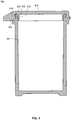
- Fig. 4 shows a cross section of such a container 900.
- a lid member 911 is closed in such a way that a sidewall 922 and an inner ring 912 provided to the lid member 911 sandwich an opening portion of a container body 901.
- the inner ring 912 is fitted to an inner peripheral surface of the opening portion of a sidewall 902 of the container body 901.
- the sidewall 922 of the lid member 911 has an inner peripheral surface on which a projection 914 is formed along the circumferential direction.
- the sidewall 902 of the container body 901 has an outer peripheral surface on which a recess 903 is formed along the circumferential direction. In the state where the lid member is closed, the projection 914 and the recess 903 are engaged with each other to lock the lid member 911 so as not to be opened.
- An object of the present invention is to provide a container that has a lid member coupled to a container body by a hinge, the container enabling easier and reliable closing operation of the lid member while improving the design.
- An aspect of the present invention is a container that includes a cylindrical container body, and a lid member coupled to the container body by a hinge so as to be openable/closable relative to an opening portion of the container body.
- the lid member has a top panel and an inner ring formed on the top panel, the inner ring being fitted to an inner peripheral surface of a sidewall of the container body in a closed state to seal the container body.
- the inner ring has an outer peripheral surface on which an outer peripheral surface projection is formed along a circumferential direction
- the container body has an inner peripheral surface on which an inner peripheral surface projection is formed along the circumferential direction, in the vicinity of an end portion of the sidewall.
- the inner ring When closing the lid member, the inner ring may seal the container body after the outer peripheral surface projection contacts and slides over the inner peripheral surface projection.
- the lid member and the end portion of the sidewall of the container body may have the same outer diameter, and in a closed state, the top panel of the lid member may come in contact with the end portion of the sidewall of the container body.
- the lid member may have a peripheral edge portion on an opposite side to where the lid member is coupled to the hinge, the peripheral edge portion being formed with a flange having an upper surface flush with an upper surface of the top panel of the lid member.
- closing of the lid member can be carried out more easily and reliably, while improving the design.
- the container 100 includes a cylindrical container body 101 having a sidewall 102, and a lid member 111.
- the container body 101 and the lid member 111 are coupled to each other by a hinge 121.
- Fig. 1 is a longitudinal cross section of the container 100 in a state where the lid member 111 is closed, taken by a plane that passes through a central axis of the container body 101 and the hinge 121.
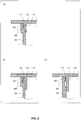
- Fig. 2(a) is a partial enlarged view of the longitudinal cross section shown in Fig. 1 .
- the lid member 111 has a top panel 113 and an inner ring 112.
- the inner ring 112 is formed on the top panel 113, and fitted to the inner peripheral surface of the sidewall 102 of the container body 101 to seal the container body 101, in the state where the lid member 111 is closed.
- the inner ring 112 has an outer peripheral surface on which an outer peripheral surface projection 114 is formed along the circumferential direction. Also, the sidewall 102 of the container body 101 has an inner peripheral surface on which an inner peripheral surface projection 103 is formed along the circumferential direction, in the vicinity of the end portion.
- the outer peripheral surface projection 114 comes into contact with and slides over the inner peripheral surface projection 103 to thereby lock the lid member 111 to the container body 101, with the inner ring 112 sealing the container body 101.
- the lid member 111 has a peripheral edge portion which faces a portion where the lid member 111 is coupled to the hinge 121.
- the peripheral edge portion is formed with a flange 115.
- the flange 115 and the top panel 113 are preferably shaped such that the respective upper surfaces are flush with each other to provide a planar surface.
- the inner ring 112 has a cross section in a doglegged shape.
- the sidewall 102 of the container body 101 is in a curved shape to facilitate elastic deformation, described later, and relieve stiffness.
- the inner ring 112 has an outer peripheral surface projection 114 having a chamfered and rounded triangular cross section. In the cross section, the inner peripheral surface projection 103 of the sidewall 102 and its vicinity are shaped in conformity with the outer peripheral surface of the inner ring 112, and are curved to relieve stiffness.
- a rib is formed as the outer peripheral surface projection 114, and the thickness of the sidewall 102 is decreased in the portion right beneath the inner peripheral surface projection 103 to thereby relieve stiffness. In this way, the cross-sectional shape of the inner ring 112 and the sidewall 102 can be varied.
- the outer peripheral surface projection 114 may be formed throughout the perimeter of the inner ring 112, or may be partially formed along the circumferential direction. To secure strength, a plurality of ribs may be formed on the top panel 113 so as to radially extend from the center.
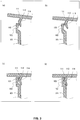
- FIG. 3 is a set of diagrams showing, as an example, cross sections in the vicinity of the flange 115 of the container 100 in the process of opening/closing the lid member 111 shown in Fig. 2(a) .
- the outer peripheral surface projection 114 When closing the lid member 111 from its opened state using the hinge 121 as an axis, the outer peripheral surface projection 114 firstly comes into contact with the inner peripheral surface projection 103 as shown in Fig. 3(a) .
- the sidewall 102 elastically deforms radially outward
- the inner ring 112 elastically deforms radially inward.
- the outer peripheral surface projection 114 comes into contact with and slides over the inner peripheral surface projection 103.
- the expression “slides over” refers to the fact that the peak portion of the outer peripheral surface projection 114 passes over the peak portion of the inner peripheral surface projection 103, and then the sidewall 102 and the inner ring 112 start recovering from the deformed state.
- the inner ring 112 contacts and slides over the sidewall 102 so as to be fitted thereto to thereby seal the container body 101.
- the lid member 111 and the container body 101 are locked to each other, and recovery from the deformed state is completed to thereby close the container body 101.
- the container body 101 is sealed after the outer peripheral surface projection 114 slides over the inner peripheral surface projection 103. This is because the amount of the fitting that continues after completion of the sealing can be made small, and the inner pressure of the container body 100 is unlikely to rise.
- the timing for the outer peripheral surface projection 114 and the inner ring 112 to contact the sidewall 102, and the timing for the inner ring 112 to conduct sealing may be different from what is described above. It is preferred that there is a gap of approximately 0.02 mm in the engaged portion in the closed state.
- the lid member 111 when closing the lid member 111, contacts the sidewall 102 of the container body 101, via the inner ring 112, only from inside the sidewall 102. Also, the lid member 111 does not cover the outer peripheral surface of the sidewall 102 of the container body 101.
- the inner ring 112 favorably functions as a guide for adjusting position, making it easier for the central axes of the lid member 111 and the container body 101 to align with each other in the course of achieving the closed state.
- the outer peripheral surface projection 114 slides over the inner peripheral surface projection 103, the sidewall 102 is expanded radially outward. This reduces friction at the time when the end of the inner ring 112 is fitted to the inner peripheral surface of the sidewall 102. For these reasons, resistance that would be caused by unnecessary interference between the lid member 111 and the container body 101 can be prevented from occurring, thereby enabling stable opening/closing motion with a small force.
- the sealing performance can be improved.
- the flange 115 can be made small.
- the closing operation can also be conducted by depressing the center of the top panel 113.
- the closed state can be directly and visually confirmed.
- insufficient closing can be prevented because the insufficiency of the closing operation can be immediately detected by at least confirming floating of the lid member 111 from the container body 101 due to partial non-contact of the top panel 113 with the sidewall 102.
- the planar top panel 113 can cover at least the opening portion of the container body 101, providing a fine look to the container and improves design.
- the push-down surface of the flange 115 is prevented from hanging over the sidewall 102 of the container body 101.
- the stroke of pushing up/down the flange 115 at the time of opening/closing the container is reduced.
- the present invention is useful as a container that includes a container body and a lid member sealing an opening portion of the container body.
- the present invention is useful as a container for accommodating pharmaceutical products, reagents and sensors such as for blood glucose level, and the like where high sealability and repetitive opening/closing are required.
Landscapes
- Engineering & Computer Science (AREA)
- Mechanical Engineering (AREA)
- Closures For Containers (AREA)
Abstract
Description
- The present invention relates to a container that includes a container body and a lid member that seals an opening portion of the container body.
- There is known a container that includes a lid member coupled to a container body by a hinge so as to be openable/closable relative to an opening portion of the container body.
Fig. 4 shows a cross section of such acontainer 900. In thecontainer 900, alid member 911 is closed in such a way that asidewall 922 and aninner ring 912 provided to thelid member 911 sandwich an opening portion of acontainer body 901. At this time, in order to enhance sealing properties, theinner ring 912 is fitted to an inner peripheral surface of the opening portion of asidewall 902 of thecontainer body 901. Thesidewall 922 of thelid member 911 has an inner peripheral surface on which aprojection 914 is formed along the circumferential direction. Thesidewall 902 of thecontainer body 901 has an outer peripheral surface on which arecess 903 is formed along the circumferential direction. In the state where the lid member is closed, theprojection 914 and therecess 903 are engaged with each other to lock thelid member 911 so as not to be opened. - [PTL 1]
JP 2008-297010 A - In such a container, when closing the lid member, the projection slides over the opening portion of the container body. In this case, the sidewall of the lid member receives resistance from the opening portion, which results in displacement and expansion of the sidewall radially outward. In conformity with this displacement, the inner ring is also displaced and expands radially outward. Thus, a large force is needed for closing the lid member, because the inner ring has to be strongly pressed against the inner wall of the opening portion when the inner ring is fitted to an inner wall. Further, since the sidewall is provided to a lid member, the outer diameter of the lid member is increased accordingly, which may lead to degradation of the design. Additionally, since the sidewall and the inner ring of the lid member sandwich the container body, closing the lid member narrows the path for the air to escape and raises the inner pressure. Consequently, the lid tends to float in a closed state, which may lead to insufficient sealing of the container, or opening of the lid when not desired.
- An object of the present invention is to provide a container that has a lid member coupled to a container body by a hinge, the container enabling easier and reliable closing operation of the lid member while improving the design.
- An aspect of the present invention is a container that includes a cylindrical container body, and a lid member coupled to the container body by a hinge so as to be openable/closable relative to an opening portion of the container body. The lid member has a top panel and an inner ring formed on the top panel, the inner ring being fitted to an inner peripheral surface of a sidewall of the container body in a closed state to seal the container body. The inner ring has an outer peripheral surface on which an outer peripheral surface projection is formed along a circumferential direction, and the container body has an inner peripheral surface on which an inner peripheral surface projection is formed along the circumferential direction, in the vicinity of an end portion of the sidewall. When closing the lid member, the outer peripheral surface projection contacts and slides over the inner peripheral surface projection to cause the lid member to be locked to the container body, with the inner ring sealing the container body.
- When closing the lid member, the inner ring may seal the container body after the outer peripheral surface projection contacts and slides over the inner peripheral surface projection.
- The lid member and the end portion of the sidewall of the container body may have the same outer diameter, and in a closed state, the top panel of the lid member may come in contact with the end portion of the sidewall of the container body.
- The lid member may have a peripheral edge portion on an opposite side to where the lid member is coupled to the hinge, the peripheral edge portion being formed with a flange having an upper surface flush with an upper surface of the top panel of the lid member.
- In the container of the present invention having the lid member coupled to the container body by a hinge, closing of the lid member can be carried out more easily and reliably, while improving the design.
-
-
Fig. 1 is a cross section of a container according to an embodiment of the present invention. -
Fig. 2 is a set of diagrams in which (a) is a partial enlarged cross section of a container according to an embodiment of the present invention, and (b) and (c) are partial enlarged cross sections of containers according to modifications of the present invention. -
Fig. 3 is a set of diagrams in which (a), (b), (c) and (d) each show a partial enlarged cross section of a container according to an embodiment of the present invention. -
Fig. 4 is a cross section of a conventional container. - A
container 100 according to an embodiment of the present invention will be described. Thecontainer 100 includes acylindrical container body 101 having asidewall 102, and alid member 111. Thecontainer body 101 and thelid member 111 are coupled to each other by ahinge 121.Fig. 1 is a longitudinal cross section of thecontainer 100 in a state where thelid member 111 is closed, taken by a plane that passes through a central axis of thecontainer body 101 and thehinge 121.Fig. 2(a) is a partial enlarged view of the longitudinal cross section shown inFig. 1 . - The
lid member 111 has atop panel 113 and aninner ring 112. Theinner ring 112 is formed on thetop panel 113, and fitted to the inner peripheral surface of thesidewall 102 of thecontainer body 101 to seal thecontainer body 101, in the state where thelid member 111 is closed. - The
inner ring 112 has an outer peripheral surface on which an outerperipheral surface projection 114 is formed along the circumferential direction. Also, thesidewall 102 of thecontainer body 101 has an inner peripheral surface on which an innerperipheral surface projection 103 is formed along the circumferential direction, in the vicinity of the end portion. - When closing the
lid member 111, the outerperipheral surface projection 114 comes into contact with and slides over the innerperipheral surface projection 103 to thereby lock thelid member 111 to thecontainer body 101, with theinner ring 112 sealing thecontainer body 101. - The
lid member 111 has a peripheral edge portion which faces a portion where thelid member 111 is coupled to thehinge 121. The peripheral edge portion is formed with aflange 115. Theflange 115 and thetop panel 113 are preferably shaped such that the respective upper surfaces are flush with each other to provide a planar surface. - In the example shown in
Fig. 2(a) , theinner ring 112 has a cross section in a doglegged shape. Thesidewall 102 of thecontainer body 101 is in a curved shape to facilitate elastic deformation, described later, and relieve stiffness. In another example shown inFig. 2(b) , theinner ring 112 has an outerperipheral surface projection 114 having a chamfered and rounded triangular cross section. In the cross section, the innerperipheral surface projection 103 of thesidewall 102 and its vicinity are shaped in conformity with the outer peripheral surface of theinner ring 112, and are curved to relieve stiffness. In another example shown inFig.2(c) , a rib is formed as the outerperipheral surface projection 114, and the thickness of thesidewall 102 is decreased in the portion right beneath the innerperipheral surface projection 103 to thereby relieve stiffness. In this way, the cross-sectional shape of theinner ring 112 and thesidewall 102 can be varied. - The outer
peripheral surface projection 114 may be formed throughout the perimeter of theinner ring 112, or may be partially formed along the circumferential direction. To secure strength, a plurality of ribs may be formed on thetop panel 113 so as to radially extend from the center. - An example of how the
lid member 111 is opened/closed will hereinafter be described.Fig. 3 is a set of diagrams showing, as an example, cross sections in the vicinity of theflange 115 of thecontainer 100 in the process of opening/closing thelid member 111 shown inFig. 2(a) . - When closing the
lid member 111 from its opened state using thehinge 121 as an axis, the outerperipheral surface projection 114 firstly comes into contact with the innerperipheral surface projection 103 as shown inFig. 3(a) . - Afterwards, as shown in
Fig. 3(b) , thesidewall 102 elastically deforms radially outward, and theinner ring 112 elastically deforms radially inward. Further, as shown inFig. 3(c) , the outerperipheral surface projection 114 comes into contact with and slides over the innerperipheral surface projection 103. The expression "slides over" refers to the fact that the peak portion of the outerperipheral surface projection 114 passes over the peak portion of the innerperipheral surface projection 103, and then thesidewall 102 and theinner ring 112 start recovering from the deformed state. - Afterwards, as shown in
Fig. 3(d) , theinner ring 112 contacts and slides over thesidewall 102 so as to be fitted thereto to thereby seal thecontainer body 101. At the same time, with the outerperipheral surface projection 114 and the innerperipheral surface projection 103 being engaged with each other, thelid member 111 and thecontainer body 101 are locked to each other, and recovery from the deformed state is completed to thereby close thecontainer body 101. In such a way, it is preferred that thecontainer body 101 is sealed after the outerperipheral surface projection 114 slides over the innerperipheral surface projection 103. This is because the amount of the fitting that continues after completion of the sealing can be made small, and the inner pressure of thecontainer body 100 is unlikely to rise. However, not being limited to this, the timing for the outerperipheral surface projection 114 and theinner ring 112 to contact thesidewall 102, and the timing for theinner ring 112 to conduct sealing may be different from what is described above. It is preferred that there is a gap of approximately 0.02 mm in the engaged portion in the closed state. - When the
lid member 111 is opened from the closed state using thehinge 121 as an axis, a process that is the reverse of the process described above is taken. Specifically, from the state shown inFig. 3(d) , theinner ring 112 slides over and becomes separated from the inner peripheral surface of the container body 101 (Fig. 3(c) ), and then, the peak portion of the outerperipheral surface projection 114 slides over the peak portion of the inner peripheral surface projection 103 (Fig. 3(b) and Fig. 3(a) ), with thesidewall 102 and theinner ring 112 elastically deformed. Further, the outerperipheral surface projection 114 is separated from the innerperipheral surface projection 103, exposing the opening portion of thecontainer body 101, to thereby open thecontainer body 101. The same applies to other examples shown in (b) and (c) ofFig. 2 . - In the
container 100, when closing thelid member 111, thelid member 111 contacts thesidewall 102 of thecontainer body 101, via theinner ring 112, only from inside thesidewall 102. Also, thelid member 111 does not cover the outer peripheral surface of thesidewall 102 of thecontainer body 101. - Therefore, the
inner ring 112 favorably functions as a guide for adjusting position, making it easier for the central axes of thelid member 111 and thecontainer body 101 to align with each other in the course of achieving the closed state. When the outerperipheral surface projection 114 slides over the innerperipheral surface projection 103, thesidewall 102 is expanded radially outward. This reduces friction at the time when the end of theinner ring 112 is fitted to the inner peripheral surface of thesidewall 102. For these reasons, resistance that would be caused by unnecessary interference between thelid member 111 and thecontainer body 101 can be prevented from occurring, thereby enabling stable opening/closing motion with a small force. Accordingly, by increasing the contact area of theinner ring 112 with the inner peripheral surface of thesidewall 102, the sealing performance can be improved. Further, theflange 115 can be made small. Also, the closing operation can also be conducted by depressing the center of thetop panel 113. - In addition, since the
top panel 113 of thelid member 111 is in contact with thesidewall 102 of thecontainer body 101 in a closed state, the closed state can be directly and visually confirmed. Thus, insufficient closing can be prevented because the insufficiency of the closing operation can be immediately detected by at least confirming floating of thelid member 111 from thecontainer body 101 due to partial non-contact of thetop panel 113 with thesidewall 102. - By allowing the
lid member 111 and the end portion of thesidewall 102 of thecontainer body 101 to have the same outer diameter, the planartop panel 113 can cover at least the opening portion of thecontainer body 101, providing a fine look to the container and improves design. By aligning the side surfaces so that the peripheral edge of thelid member 111 does not protrude, undesired opening of thelid member 111 is prevented, which would otherwise occur by the impact of dropping that locally works on thelid member 111. - Since the air easily escapes during closing motion of the
lid member 111, the inner pressure inside the container is unlikely to rise, and thelid member 111 is unlikely to float in the closed state. Therefore, the closed state is stably maintained. - By providing a shape in which the upper surface of the
flange 115 is flush with the upper surface of thetop panel 113, the push-down surface of theflange 115 is prevented from hanging over thesidewall 102 of thecontainer body 101. Thus, the stroke of pushing up/down theflange 115 at the time of opening/closing the container is reduced. - As described above, in the container having the lid member connected to the container body by a hinge according to the present invention, closing operation of the lid member can be conducted more easily and reliably, while improving the design. The features mentioned above may be omitted or modified as appropriate.
- The present invention is useful as a container that includes a container body and a lid member sealing an opening portion of the container body. Specifically, the present invention is useful as a container for accommodating pharmaceutical products, reagents and sensors such as for blood glucose level, and the like where high sealability and repetitive opening/closing are required.
-
- 100
- Container
- 101
- Container body
- 102
- Sidewall
- 103
- Inner peripheral surface projection
- 104
- First inner peripheral surface
- 105
- Second inner peripheral surface
- 111
- Lid member
- 112
- Inner ring
- 113
- Top panel
- 114
- Outer peripheral surface projection
- 115
- Flange
- 116
- Projection
- 121
- Hinge
Claims (4)
- A container comprising a cylindrical container body, and a lid member coupled to the container body by a hinge so as to be openable/closable relative to an opening portion of the container body, wherein:the lid member has a top panel and an inner ring formed on the top panel, the inner ring being fitted to an inner peripheral surface of a sidewall of the container body in a closed state to seal the container body;the inner ring has an outer peripheral surface on which an outer peripheral surface projection is formed along a circumferential direction;the container body has an inner peripheral surface on which an inner peripheral surface projection is formed along the circumferential direction, in the vicinity of an end portion of the sidewall; andwhen closing the lid member, the outer peripheral surface projection contacts and slides over the inner peripheral surface projection to cause the lid member to be locked to the container body, with the inner ring sealing the container body.
- The container body according to claim 1, wherein:when closing the lid member, the inner ring seals the container body after the outer peripheral surface projection contacts and slides over the inner peripheral surface projection.
- The container according to claim 1 or 2, wherein the lid member and the end portion of the sidewall of the container body have the same outer diameter, and in a closed state, the top panel of the lid member comes into contact with the end portion of the sidewall of the container body.
- The container according to any one of claims 1 to 3, wherein:the lid member has a peripheral edge portion facing a portion where the lid member is coupled to the hinge, the peripheral edge portion being formed with a flange having an upper surface flush with an upper surface of the top panel of the lid member.
Applications Claiming Priority (2)
| Application Number | Priority Date | Filing Date | Title |
|---|---|---|---|
| JP2015064987A JP6808911B2 (en) | 2015-03-26 | 2015-03-26 | Container with lid |
| PCT/JP2016/001207 WO2016152049A1 (en) | 2015-03-26 | 2016-03-04 | Lidded container |
Publications (2)
| Publication Number | Publication Date |
|---|---|
| EP3231727A1 true EP3231727A1 (en) | 2017-10-18 |
| EP3231727A4 EP3231727A4 (en) | 2018-01-17 |
Family
ID=56977266
Family Applications (1)
| Application Number | Title | Priority Date | Filing Date |
|---|---|---|---|
| EP16767959.6A Withdrawn EP3231727A4 (en) | 2015-03-26 | 2016-03-04 | Lidded container |
Country Status (5)
| Country | Link |
|---|---|
| US (1) | US10246227B2 (en) |
| EP (1) | EP3231727A4 (en) |
| JP (1) | JP6808911B2 (en) |
| CN (1) | CN107406174B (en) |
| WO (1) | WO2016152049A1 (en) |
Families Citing this family (14)
| Publication number | Priority date | Publication date | Assignee | Title |
|---|---|---|---|---|
| GB2536265B (en) * | 2015-03-11 | 2018-01-24 | Crown Packaging Technology Inc | Ringless metal cans |
| JP6634690B2 (en) * | 2015-03-26 | 2020-01-22 | 凸版印刷株式会社 | Container with lid |
| US10130171B2 (en) | 2017-02-08 | 2018-11-20 | Intermetro Industries Corporation | Insulated transport cabinets for food and the like |
| KR102701926B1 (en) | 2017-08-10 | 2024-09-02 | 도판 홀딩스 가부시키가이샤 | Packaging container having a spout stopper and a spout stopper |
| CN111032524B (en) * | 2017-08-10 | 2022-04-08 | 凸版印刷株式会社 | Discharge stopper and packaging container with discharge stopper |
| US20190119011A1 (en) * | 2017-10-21 | 2019-04-25 | Zipporo LLC | Sealable Container System |
| JP6942069B2 (en) * | 2018-01-31 | 2021-09-29 | 株式会社吉野工業所 | Box-shaped container |
| US10947018B2 (en) * | 2018-06-06 | 2021-03-16 | Clarity, Inc. | Cups and containers with a living hinge and sleeves |
| USD873613S1 (en) | 2018-06-07 | 2020-01-28 | Clarity, Inc. | Cup with a lid |
| EP4001155B1 (en) * | 2019-07-16 | 2024-11-13 | Jin Hee Ahn | Container cap and container combined with same |
| US11591141B2 (en) * | 2020-07-08 | 2023-02-28 | Veraseal Pty Limited | Closures and vessels with closures |
| US20230271756A1 (en) * | 2020-07-08 | 2023-08-31 | Veraseal Pty Limited | Closures and vessels with closures |
| KR102935376B1 (en) * | 2021-11-11 | 2026-03-06 | 주식회사 엘지에너지솔루션 | Battery Module Having Improved Water/Dust Proofing And Battery Pack with The Same |
| USD1120115S1 (en) | 2024-02-14 | 2026-03-24 | Rolyn Dice Limited | Dice holder |
Family Cites Families (24)
| Publication number | Priority date | Publication date | Assignee | Title |
|---|---|---|---|---|
| AT284649B (en) * | 1968-11-26 | 1970-09-25 | Empla Gmbh | Container with a stopper |
| US4639386A (en) * | 1984-02-03 | 1987-01-27 | Fuji Photo Film Co., Ltd. | Container for photographic film cartridge |
| US4730745A (en) * | 1987-03-30 | 1988-03-15 | Owens-Illinois Closure Inc. | Tamper indicating plug style closure |
| US5106665A (en) * | 1989-02-16 | 1992-04-21 | Fuji Photo Film Co., Ltd. | Container for photographic film cartridge |
| US5254314A (en) * | 1989-08-24 | 1993-10-19 | International Mould Engineering | Microcentrifuge tube |
| GB9001756D0 (en) * | 1990-01-25 | 1990-03-28 | Lin Pac Mouldings | A container |
| DE4013799A1 (en) * | 1990-04-28 | 1991-10-31 | Gaplast Gmbh | PLASTIC CONTAINER AND CONTAINER CLOSURE, ESPECIALLY FOR MEDICINAL PRODUCTS |
| JPH0678265U (en) * | 1993-04-16 | 1994-11-04 | 花王株式会社 | Container |
| AU1260895A (en) * | 1993-12-06 | 1995-06-27 | Thompson Minwax Company, The | Container with hinged lid for paint |
| JPH08324652A (en) * | 1995-05-31 | 1996-12-10 | Eastman Kodak Co | Film case |
| JPH11263359A (en) * | 1998-03-13 | 1999-09-28 | Shiseido Co Ltd | Unplugging mechanism for cap |
| JP4330198B2 (en) * | 1999-02-23 | 2009-09-16 | 吉田プラ工業株式会社 | Airtight cosmetic container |
| FR2789857B1 (en) * | 1999-02-23 | 2005-01-28 | Yoshida Industry Co | COSMETIC SEALED BOX |
| US6571942B2 (en) * | 2001-08-09 | 2003-06-03 | Multisorb Technologies, Inc. | Container with integral material-treating container and method of fabrication thereof |
| FR2858301B1 (en) * | 2003-07-29 | 2006-05-26 | Airsec | WATERPROOF DESSICATIVE CONTAINER FOR PACKAGING AMBIENT HUMIDITY-SENSITIVE PRODUCTS |
| US20050092641A1 (en) * | 2003-10-31 | 2005-05-05 | Marsden Andrew W. | Medicine container and packaging therefor |
| US8800798B2 (en) * | 2005-12-22 | 2014-08-12 | Superfos A/S | Packaging with lid sealable to container and a method of sealing the packaging |
| JP2008297010A (en) | 2007-05-31 | 2008-12-11 | Nisshin Gosei:Kk | Hinged cap integral type tube container |
| DK2207727T3 (en) * | 2007-11-16 | 2016-06-20 | Clariant Production (France) S A S | Container |
| US9428311B2 (en) * | 2007-11-16 | 2016-08-30 | Clariant Production (France) S.A.S. | Container |
| WO2012082399A1 (en) * | 2010-12-13 | 2012-06-21 | Csp Technologies, Inc. | Vial with lid attachment mechanism |
| CN102943030A (en) * | 2012-10-30 | 2013-02-27 | 无锡耐思生物科技有限公司 | Polymerase chain reaction single tube structure |
| US20150259115A1 (en) * | 2014-03-12 | 2015-09-17 | Huan-Fu Yeh | Sealed Container with Moisture-proof Function |
| US9694955B2 (en) * | 2014-12-11 | 2017-07-04 | Kush Bottles, Inc. | Unitary child-resistant containers configured for attachment to identifier cap, and identifier cap |
-
2015
- 2015-03-26 JP JP2015064987A patent/JP6808911B2/en active Active
-
2016
- 2016-03-04 CN CN201680013071.2A patent/CN107406174B/en not_active Expired - Fee Related
- 2016-03-04 EP EP16767959.6A patent/EP3231727A4/en not_active Withdrawn
- 2016-03-04 WO PCT/JP2016/001207 patent/WO2016152049A1/en not_active Ceased
-
2017
- 2017-09-12 US US15/702,699 patent/US10246227B2/en active Active
Also Published As
| Publication number | Publication date |
|---|---|
| EP3231727A4 (en) | 2018-01-17 |
| JP2016182983A (en) | 2016-10-20 |
| JP6808911B2 (en) | 2021-01-06 |
| CN107406174A (en) | 2017-11-28 |
| US10246227B2 (en) | 2019-04-02 |
| WO2016152049A1 (en) | 2016-09-29 |
| CN107406174B (en) | 2020-11-17 |
| US20180009579A1 (en) | 2018-01-11 |
Similar Documents
| Publication | Publication Date | Title |
|---|---|---|
| US10246227B2 (en) | Lidded container | |
| EP3067291B1 (en) | Lidded vessel | |
| US10611529B2 (en) | Lidded container | |
| US7891519B2 (en) | Easy open can lid | |
| EP3626641A1 (en) | Bottle-shaped can, bottle-shaped can with cap, and method for manufacturing bottle-shaped can | |
| JP2018532664A (en) | Snap engagement cover with multi-component injection molding technology | |
| EP2627573B1 (en) | A method for producing filled and reclosable pressure vessels | |
| JP2010042401A (en) | Cup for centrifuge | |
| EP3133027A1 (en) | Sealed container for pressurized beverage and manufacturing method therefor | |
| JP6292964B2 (en) | Hinge cap | |
| KR101963835B1 (en) | Secondary battery | |
| JP2019060358A (en) | Hole plug | |
| TWI706899B (en) | Bottles and cans with lids | |
| JP2005047511A (en) | container | |
| JP3224712U (en) | Sealed structure for storage containers and storage containers | |
| JP6476071B2 (en) | Cup container with lid | |
| EP2783889B1 (en) | Weather strip | |
| EP3342725A1 (en) | Packaging for receiving a filling material | |
| EP2241514B1 (en) | Container with hermetic seal | |
| JP2025006043A (en) | Hinge Cap | |
| JP6632889B2 (en) | Cap type resin cap | |
| JP2022098046A (en) | Pull-up cap with inside plug | |
| MX2025006529A (en) | Resealable container | |
| JP2002234535A (en) | Can lid |
Legal Events
| Date | Code | Title | Description |
|---|---|---|---|
| STAA | Information on the status of an ep patent application or granted ep patent |
Free format text: STATUS: THE INTERNATIONAL PUBLICATION HAS BEEN MADE |
|
| PUAI | Public reference made under article 153(3) epc to a published international application that has entered the european phase |
Free format text: ORIGINAL CODE: 0009012 |
|
| STAA | Information on the status of an ep patent application or granted ep patent |
Free format text: STATUS: REQUEST FOR EXAMINATION WAS MADE |
|
| 17P | Request for examination filed |
Effective date: 20170712 |
|
| AK | Designated contracting states |
Kind code of ref document: A1 Designated state(s): AL AT BE BG CH CY CZ DE DK EE ES FI FR GB GR HR HU IE IS IT LI LT LU LV MC MK MT NL NO PL PT RO RS SE SI SK SM TR |
|
| AX | Request for extension of the european patent |
Extension state: BA ME |
|
| A4 | Supplementary search report drawn up and despatched |
Effective date: 20171215 |
|
| RIC1 | Information provided on ipc code assigned before grant |
Ipc: B65D 43/16 20060101ALI20171212BHEP Ipc: B65D 43/22 20060101AFI20171212BHEP |
|
| DAV | Request for validation of the european patent (deleted) | ||
| DAX | Request for extension of the european patent (deleted) | ||
| STAA | Information on the status of an ep patent application or granted ep patent |
Free format text: STATUS: EXAMINATION IS IN PROGRESS |
|
| 17Q | First examination report despatched |
Effective date: 20210429 |
|
| GRAP | Despatch of communication of intention to grant a patent |
Free format text: ORIGINAL CODE: EPIDOSNIGR1 |
|
| STAA | Information on the status of an ep patent application or granted ep patent |
Free format text: STATUS: GRANT OF PATENT IS INTENDED |
|
| INTG | Intention to grant announced |
Effective date: 20240124 |
|
| STAA | Information on the status of an ep patent application or granted ep patent |
Free format text: STATUS: THE APPLICATION IS DEEMED TO BE WITHDRAWN |
|
| 18D | Application deemed to be withdrawn |
Effective date: 20240525 |