EP3231671A1 - Webbing winding device - Google Patents
Webbing winding device Download PDFInfo
- Publication number
- EP3231671A1 EP3231671A1 EP15867320.2A EP15867320A EP3231671A1 EP 3231671 A1 EP3231671 A1 EP 3231671A1 EP 15867320 A EP15867320 A EP 15867320A EP 3231671 A1 EP3231671 A1 EP 3231671A1
- Authority
- EP
- European Patent Office
- Prior art keywords
- spool
- webbing
- stopper member
- load
- torsion shaft
- Prior art date
- Legal status (The legal status is an assumption and is not a legal conclusion. Google has not performed a legal analysis and makes no representation as to the accuracy of the status listed.)
- Granted
Links
- 238000004804 winding Methods 0.000 title 1
- 238000003780 insertion Methods 0.000 claims abstract description 39
- 230000037431 insertion Effects 0.000 claims abstract description 39
- 230000008878 coupling Effects 0.000 claims description 13
- 238000010168 coupling process Methods 0.000 claims description 13
- 238000005859 coupling reaction Methods 0.000 claims description 13
- 230000000694 effects Effects 0.000 description 3
- 238000010586 diagram Methods 0.000 description 2
- 238000012986 modification Methods 0.000 description 1
- 230000004048 modification Effects 0.000 description 1
Images

Classifications
-
- B—PERFORMING OPERATIONS; TRANSPORTING
- B60—VEHICLES IN GENERAL
- B60R—VEHICLES, VEHICLE FITTINGS, OR VEHICLE PARTS, NOT OTHERWISE PROVIDED FOR
- B60R22/00—Safety belts or body harnesses in vehicles
- B60R22/34—Belt retractors, e.g. reels
- B60R22/36—Belt retractors, e.g. reels self-locking in an emergency
-
- B—PERFORMING OPERATIONS; TRANSPORTING
- B60—VEHICLES IN GENERAL
- B60R—VEHICLES, VEHICLE FITTINGS, OR VEHICLE PARTS, NOT OTHERWISE PROVIDED FOR
- B60R22/00—Safety belts or body harnesses in vehicles
- B60R22/34—Belt retractors, e.g. reels
-
- B—PERFORMING OPERATIONS; TRANSPORTING
- B60—VEHICLES IN GENERAL
- B60R—VEHICLES, VEHICLE FITTINGS, OR VEHICLE PARTS, NOT OTHERWISE PROVIDED FOR
- B60R22/00—Safety belts or body harnesses in vehicles
- B60R22/28—Safety belts or body harnesses in vehicles incorporating energy-absorbing devices
- B60R2022/286—Safety belts or body harnesses in vehicles incorporating energy-absorbing devices using deformation of material
- B60R2022/287—Safety belts or body harnesses in vehicles incorporating energy-absorbing devices using deformation of material of torsion rods or tubes
-
- B—PERFORMING OPERATIONS; TRANSPORTING
- B60—VEHICLES IN GENERAL
- B60R—VEHICLES, VEHICLE FITTINGS, OR VEHICLE PARTS, NOT OTHERWISE PROVIDED FOR
- B60R22/00—Safety belts or body harnesses in vehicles
- B60R22/34—Belt retractors, e.g. reels
- B60R2022/3427—Seat belt connection on reels
Definitions
- the present invention relates to a webbing take-up device.
- JP-A No. 2008-1194 discloses a webbing take-up device provided with: a spool (a bobbin) that is turnably supported and onto which a webbing is taken up; and a stopper (a belt plate) to which one end of the webbing is fixed.
- the end portion of the webbing is secured at the spool by a central portion of the stopper engaging with an engaging portion formed in the spool and two end portions (securing portions) of the stopper being set in setting portions formed in the spool.
- an object of the present invention is to provide a webbing take-up device that may suppress an increase in diameter of a spool.
- a webbing take-up device includes: a spool including a webbing insertion hole at which a webbing to be applied to a vehicle occupant is inserted, the webbing being taken up onto the spool, and the spool being turned in a pull-out direction when the webbing is pulled out; a stopper member provided at an end portion of the webbing, the stopper member securing the end portion of the webbing at the spool by engaging with a periphery portion of the webbing insertion hole; and a load bracing portion disposed at a diametric direction inner side of the spool relative to the stopper member, the load bracing portion bracing a load that is applied to the spool from the webbing via the stopper member.
- the stopper member is formed in a long shape whose length direction is along an axial direction of the spool; and the load bracing portion is provided at each of locations of end portions at a length direction one side and another side of the stopper member, which locations oppose the spool in the diametric direction.
- a lock portion is provided at an axial direction one side of the spool, turning of the lock portion in the pull-out direction being limited during an emergency state of a vehicle;
- a torsion shaft is provided at an axial central portion of the spool, a portion of the torsion shaft serving as a first coupling portion that is coupled to an end portion at an axial direction another side of the spool, another portion of the torsion shaft serving as a second coupling portion that is coupled to the lock portion, and, when the turning of the lock portion is being limited, the torsion shaft allowing turning of the spool in the pull-out direction relative to the lock portion by a load of at least a force limiter load; and a portion of at least one of the first coupling portion and the second coupling portion serves as the load bracing portion.
- the webbing applied to a vehicle occupant is taken up onto the spool, and the spool is turned in the pull-out direction by the webbing being pulled out from the spool.
- the load bracing portion is provided at the diametric direction inner side of the spool relative to the stopper member, a load applied to the spool from the webbing via the stopper member is braced by the load bracing portion. Therefore, deformation of a periphery portion of the webbing insertion hole due to the periphery portion of the webbing insertion hole being pressed by the stopper member can be suppressed. That is, a rise in stress values produced in the periphery portion of the webbing insertion hole can be suppressed.
- an increase in thickness of the periphery portion of the webbing insertion hole may be moderated and an increase in diameter of the spool may be suppressed.
- deformation of the periphery portion of the webbing insertion hole that is pressed by the stopper member may be effectively suppressed by the load bracing portion being provided at each of the locations that oppose, in the diametric direction of the spool, the end portion at the length direction one side of the stopper member and the end portion at the another side.
- an increase in a number of components structuring the webbing take-up device may be suppressed by the load bracing portions being portions of the torsion shaft.
- the structure of the torsion shaft may be simplified by a portion of at least one of the first coupling portion and the second coupling portion serving as the load bracing portion.
- a webbing take-up device is described using Fig. 1 to Fig. 4 .
- the directions of arrow Z, arrow R and arrow C that are shown as appropriate in the drawings indicate, respectively, an axial direction of the spool, a diametric direction of the spool and a circumferential direction of the spool. Where an axial direction, diametric direction or circumferential direction is referred to herebelow, these refer to the axial direction, diametric direction or circumferential direction of the spool unless specifically stated otherwise.
- a webbing take-up device 10 is provided with a spool 14 and a lock mechanism 18.
- a webbing 12 to be applied to a vehicle occupant is taken up onto the spool 14, and the spool 14 is turned in a pull-out direction by the webbing 12 being pulled out.
- the lock mechanism 18 is provided to be turnable integrally with the spool 14 and includes a lock portion 16. Turning of the lock portion 16 in the pull-out direction is limited (restricted) during an emergency state of a vehicle.
- the webbing take-up device 10 is further provided with a force limiter mechanism 20 that, when turning of the lock portion 16 is being restricted, allows turning of the spool 14 in the pull-out direction relative to the lock portion 16 by a load that is at least a force limiter load.
- the spool 14 is provided with a take-up portion 14A that is formed in a substantially circular rod shape and onto which the webbing 12 is taken up.
- a webbing insertion hole 14B is formed in the take-up portion 14A.
- the webbing 12 is inserted into the webbing insertion hole 14B.
- the webbing insertion hole 14B is formed in a rectangular shape whose length direction is in the axial direction.
- a dimension of one side opening portion of the webbing insertion hole 14B in the short direction thereof is specified to be smaller toward the axial center of the spool 14.
- a stopper member insertion portion 12A is formed at an end portion of the long direction of the webbing 12.
- the stopper member insertion portion 12A is formed by the end portion of the long direction of the webbing 12 being folded back and sewn to itself. After the webbing 12 is inserted into the webbing insertion hole 14B, a stopper member 15 is inserted into the stopper member insertion portion 12A of the webbing 12.
- the end portion of the long direction of the webbing 12 is secured at the spool 14 by the webbing 12 being pulled in the pull-out direction and the stopper member 15 that is inserted into the stopper member insertion portion 12A of the webbing 12 being caught at a periphery portion 14H at the one side opening portion of the webbing insertion hole 14B.
- the webbing 12 extends to the upper side from a frame 24 at which the spool 14 is turnably supported, and can be applied to a vehicle occupant sitting on a seat (not shown in the drawings) of the vehicle.
- a circumferential direction another side the direction opposite to the direction of arrow C
- the webbing 12 is taken up onto the spool 14, and when the webbing 12 is pulled out from the spool 14, the spool 14 is turned to a circumferential direction one side (the direction of arrow C), which is to say the spool 14 is turned in the pull-out direction.
- An engaging teeth portion 14C is provided at an end portion at an axial direction another side of the spool 14 (the direction opposite to the direction of arrow Z).
- the engaging teeth portion 14C constitutes a portion of a pre-tensioner mechanism 26 (see Fig. 1 ).
- the pre-tensioner mechanism 26 When there is an emergency state of the vehicle, the pre-tensioner mechanism 26 forcibly turns the spool 14 in the take-up direction of the webbing 12.
- a torsion shaft insertion hole 14D is formed at an axial central portion of the spool 14.
- a torsion shaft 34 which is described below, is inserted into the torsion shaft insertion hole 14D.
- An inner diameter (a minimum internal diameter) of the torsion shaft insertion hole 14D is set to be slightly larger than an outer diameter of a first serrated portion 34A, which serves as a first coupling portion.
- the first serrated portion 34A is formed at an end portion at the axial direction another side of the torsion shaft 34.
- a first serrated portion engaging portion 14G is formed at an end portion at the axial direction another side of the torsion shaft insertion hole 14D.
- the first serrated portion 34A of the torsion shaft 34 engages with the first serrated portion engaging portion 14G. Seen from the axial direction one side, an inner edge portion of the first serrated portion engaging portion 14G is formed in a shape that corresponds with the shape of an outer edge portion of the first serrated portion 34A.
- the end portion at the axial direction another side of the torsion shaft 34 and the spool 14 are coupled to be integrally turnable by the first serrated portion 34A of the torsion shaft 34 engaging with the first serrated portion engaging portion 14G.
- the coupling of the first serrated portion 34A of the torsion shaft 34 with the first serrated portion engaging portion 14G is prevented from disengaging by a first support member, which is not shown in the drawings, that is attached to the spool 14.
- the lock mechanism 18 includes the lock portion 16, which is provided at the axial direction one side of the spool 14, and a lock piece 32, which is attached to the lock portion 16.
- the lock portion 16 is formed in a substantially circular plate shape whose thickness direction is along the axial direction.
- a first engagement receiving tooth 16C is formed at the lock portion 16.
- the first engagement receiving tooth 16C engages with ratchet teeth, which are not shown in the drawing, that are provided at the frame 24 (see Fig. 1 ) during an emergency state of the vehicle (during a collision of the vehicle, when the spool 14 is suddenly pulled out from the webbing 12, there is a sudden deceleration of the vehicle or the like).
- a second engagement receiving tooth 32A is formed at the lock piece 32.
- the second engagement receiving tooth 32A also engages with the ratchet teeth.
- a second serrated portion engaging portion 16A is formed at an axial central portion of the lock portion 16.
- a second serrated portion 34B which serves as a second coupling portion, engages with the second serrated portion engaging portion 16A.
- the second serrated portion 34B is formed at an end portion at the axial direction one side of the below-described torsion shaft 34.
- the second serrated portion engaging portion 16A penetrates through the axial central portion of the lock portion 16 in the axial direction. Seen from the axial direction one side, an inner edge portion of the second serrated portion engaging portion 16A is formed in a shape that corresponds with the shape of an outer edge portion of the second serrated portion 34B.
- the end portion at the axial direction one side of the torsion shaft 34 and the lock portion 16 are coupled to be integrally turnable by the second serrated portion 34B of the torsion shaft 34 engaging with the second serrated portion engaging portion 16A.
- an end face 16B at the axial direction another side of the lock portion 16 abuts against an end 14F at the axial direction one side of the spool 14.
- the force limiter mechanism 20 includes the torsion shaft 34, which is formed in a substantially circular rod shape.
- the first serrated portion 34A that engages with the first serrated portion engaging portion 14G provided at the spool 14 is formed at the end portion at the axial direction another side of the torsion shaft 34.
- a dimension L1 of the first serrated portion 34A in the axial direction is set to be longer than a dimension L2 of the first serrated portion engaging portion 14G in the axial direction.
- the second serrated portion 34B that engages with the second serrated portion engaging portion 16A provided at the lock portion 16 is formed at the end portion at the axial direction one side of the torsion shaft 34.
- An outer diameter of the second serrated portion 34B is set to be larger than an outer diameter of the first serrated portion 34A.
- a dimension L3 of the second serrated portion 34B in the axial direction is set to be longer than a dimension L4 of the second serrated portion engaging portion 16A in the axial direction. Consequently, a portion P3 at the axial direction one side of the second serrated portion 34B engages with the second serrated portion engaging portion 16A and a portion P4 at the axial direction another side of the second serrated portion 34B does not engage with the second serrated portion engaging portion 16A.
- a portion of the torsion shaft 34 at the axial direction another side relative to the second serrated portion 34B is a rod portion 34E that is formed in a substantially circular rod shape.
- An outer diameter of the rod portion 34E is set to be slightly larger than the inner diameter (minimum internal diameter) of the torsion shaft insertion hole 14D and to be substantially the same as the outer diameter of the first serrated portion 34A.
- the outer diameter of the rod portion 34E substantially matches a diameter of valleys of the second serrated portion 34B.
- a portion of the torsion shaft 34 between the rod portion 34E and the first serrated portion 34A serves as a twisting portion 34F, which is specified with an outer diameter smaller than the outer diameter of the rod portion 34E.
- the portion P2 at the axial direction one side of the first serrated portion 34A which serves as a load bracing portion, is disposed to oppose an end portion 15A at a long direction another side of the stopper member 15 in the diametric direction.
- Outer periphery faces of the portion P2 at the axial direction one side of the first serrated portion 34A and the portion P5 at the axial direction another side of the rod portion 34E are disposed to be close to inner periphery faces of minimum internal diameter portions of the torsion shaft insertion hole 14D.
- a supported portion 34C is provided at the axial direction one side of the torsion shaft 34 relative to the second serrated portion 34B.
- the supported portion 34C is supported by a second support member, which is not shown in the drawings.
- a flange portion 34D is provided at a boundary between the supported portion 34C and the second serrated portion 34B.
- the flange portion 34D has a larger diameter than the second serrated portion 34B. Movement of the torsion shaft 34 to the axial direction another side relative to the lock portion 16 is restricted by the flange portion 34D abutting against the lock portion 16.
- the webbing 12 is pulled out from the spool 14 and applied to a vehicle occupant sitting on a seat of a vehicle, which is not shown in the drawings.
- the outer periphery faces of the portion P2 at the axial direction one side of the first serrated portion 34A and the portion P5 at the axial direction another side of the rod portion 34E that are formed at the torsion shaft 34 are close to the inner periphery faces of the torsion shaft insertion hole 14D formed in the axial central portion of the spool 14. Therefore, in the state in which the webbing 12 that was taken up onto the spool 14 has been completely pulled out from the spool 14, if the webbing 12 is pulled further in the pull-out direction, the stopper member 15 installed at the end portion of the webbing 12 presses against the periphery portion 14H of the webbing insertion hole 14B formed in the spool 14.
- the periphery portion 14H of the webbing insertion hole 14B deforms slightly toward the diametric direction inner side.
- the inner periphery face of the torsion shaft insertion hole 14D abuts against the portion P2 at the axial direction one side of the first serrated portion 34A and the outer periphery face of the portion P5 at the axial direction another side of the rod portion 34E that are formed at the torsion shaft 34. Therefore, deformation of the periphery portion 14H of the webbing insertion hole 14B due to the periphery portion 14H of the webbing insertion hole 14B being pressed against by the stopper member 15 is suppressed.
- an increase in thickness of the periphery portion 14H of the webbing insertion hole 14B may be moderated and an increase in diameter of the spool 14 may be suppressed.
- the portion P2 at the axial direction one side of the first serrated portion 34A and the portion P5 at the axial direction another side of the rod portion 34E that are formed at the torsion shaft 34 are provided at positions opposing in the diametric direction, respectively, the end portion 15A at the length direction another side and the end portion 15B at the length direction one side of the stopper member 15. Therefore, deformation of the periphery portion 14H of the webbing insertion hole 14B being pressed by the stopper member 15 may be suppressed effectively.
- the present exemplary embodiment is a structure in which a load applied from the stopper member 15 to the periphery portion 14H of the webbing insertion hole 14B formed in the spool 14 is braced by a portion of the torsion shaft 34. Therefore, compared to a structure in which an alternative member is additionally provided in order to brace this load, an increase in the number of components structuring the webbing take-up device 10 may be suppressed.
- a load bracing portion that braces this load may be disposed at a position that opposes a length direction middle portion of the stopper member 15 in the diametric direction.
- the arrangement of load bracing portions is specified appropriately in consideration of the shape of the stopper member 15, stress distribution in the periphery portion 14H of the webbing insertion hole 14B, and the like.
Landscapes
- Engineering & Computer Science (AREA)
- Mechanical Engineering (AREA)
- Automotive Seat Belt Assembly (AREA)
Abstract
Description
- The present invention relates to a webbing take-up device.
- Japanese Patent Application Laid-Open (
JP-A) No. 2008-1194 JP-A No. 2008-1194 - However, in the structure recited in
JP-A No. 2008-1194 - In consideration of the circumstances described above, an object of the present invention is to provide a webbing take-up device that may suppress an increase in diameter of a spool.
- A webbing take-up device according to a first aspect of the present invention includes: a spool including a webbing insertion hole at which a webbing to be applied to a vehicle occupant is inserted, the webbing being taken up onto the spool, and the spool being turned in a pull-out direction when the webbing is pulled out; a stopper member provided at an end portion of the webbing, the stopper member securing the end portion of the webbing at the spool by engaging with a periphery portion of the webbing insertion hole; and a load bracing portion disposed at a diametric direction inner side of the spool relative to the stopper member, the load bracing portion bracing a load that is applied to the spool from the webbing via the stopper member.
- In a webbing take-up device according to a second aspect of the present invention, in the webbing take-up device of the first aspect: the stopper member is formed in a long shape whose length direction is along an axial direction of the spool; and the load bracing portion is provided at each of locations of end portions at a length direction one side and another side of the stopper member, which locations oppose the spool in the diametric direction.
- In a webbing take-up device according to a third aspect of the present invention, in the webbing take-up device of the second aspect: a lock portion is provided at an axial direction one side of the spool, turning of the lock portion in the pull-out direction being limited during an emergency state of a vehicle; a torsion shaft is provided at an axial central portion of the spool, a portion of the torsion shaft serving as a first coupling portion that is coupled to an end portion at an axial direction another side of the spool, another portion of the torsion shaft serving as a second coupling portion that is coupled to the lock portion, and, when the turning of the lock portion is being limited, the torsion shaft allowing turning of the spool in the pull-out direction relative to the lock portion by a load of at least a force limiter load; and a portion of at least one of the first coupling portion and the second coupling portion serves as the load bracing portion.
- In the webbing take-up device of the first aspect of the present invention, the webbing applied to a vehicle occupant is taken up onto the spool, and the spool is turned in the pull-out direction by the webbing being pulled out from the spool.
- In the present invention, because the above-mentioned load bracing portion is provided at the diametric direction inner side of the spool relative to the stopper member, a load applied to the spool from the webbing via the stopper member is braced by the load bracing portion. Therefore, deformation of a periphery portion of the webbing insertion hole due to the periphery portion of the webbing insertion hole being pressed by the stopper member can be suppressed. That is, a rise in stress values produced in the periphery portion of the webbing insertion hole can be suppressed. Thus, with the present invention, an increase in thickness of the periphery portion of the webbing insertion hole may be moderated and an increase in diameter of the spool may be suppressed.
- According to the webbing take-up device of the second aspect of the present invention, deformation of the periphery portion of the webbing insertion hole that is pressed by the stopper member may be effectively suppressed by the load bracing portion being provided at each of the locations that oppose, in the diametric direction of the spool, the end portion at the length direction one side of the stopper member and the end portion at the another side.
- According to the webbing take-up device of the third aspect of the present invention, an increase in a number of components structuring the webbing take-up device may be suppressed by the load bracing portions being portions of the torsion shaft. Furthermore, the structure of the torsion shaft may be simplified by a portion of at least one of the first coupling portion and the second coupling portion serving as the load bracing portion.
-
-
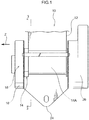
Fig. 1 is a front view showing a webbing take-up device. -
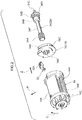
Fig. 2 is an exploded perspective view showing a spool, a lock portion and a torsion shaft structuring portions of the webbing take-up device shown inFig. 1 . -
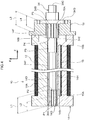
Fig. 3 is a magnified sectional diagram showing the spool, a stopper member, a webbing and the torsion shaft, cut along line 3-3 inFig. 1 . -
Fig. 4 is a magnified sectional diagram showing a section of the webbing take-up device cut along line 4-4 inFig. 3 . - A webbing take-up device according to an exemplary embodiment of the present invention is described using
Fig. 1 to Fig. 4 . The directions of arrow Z, arrow R and arrow C that are shown as appropriate in the drawings indicate, respectively, an axial direction of the spool, a diametric direction of the spool and a circumferential direction of the spool. Where an axial direction, diametric direction or circumferential direction is referred to herebelow, these refer to the axial direction, diametric direction or circumferential direction of the spool unless specifically stated otherwise. - As shown in
Fig. 1 andFig. 2 , a webbing take-up device 10 according to the present exemplary embodiment is provided with aspool 14 and alock mechanism 18. Awebbing 12 to be applied to a vehicle occupant is taken up onto thespool 14, and thespool 14 is turned in a pull-out direction by thewebbing 12 being pulled out. Thelock mechanism 18 is provided to be turnable integrally with thespool 14 and includes alock portion 16. Turning of thelock portion 16 in the pull-out direction is limited (restricted) during an emergency state of a vehicle. The webbing take-up device 10 is further provided with aforce limiter mechanism 20 that, when turning of thelock portion 16 is being restricted, allows turning of thespool 14 in the pull-out direction relative to thelock portion 16 by a load that is at least a force limiter load. - As shown in
Fig. 2 , thespool 14 is provided with a take-up portion 14A that is formed in a substantially circular rod shape and onto which thewebbing 12 is taken up. Awebbing insertion hole 14B is formed in the take-up portion 14A. Thewebbing 12 is inserted into thewebbing insertion hole 14B. Viewed from the diametric direction outer side, thewebbing insertion hole 14B is formed in a rectangular shape whose length direction is in the axial direction. A dimension of one side opening portion of thewebbing insertion hole 14B in the short direction thereof is specified to be smaller toward the axial center of thespool 14. - As shown in
Fig. 3 , a stoppermember insertion portion 12A is formed at an end portion of the long direction of thewebbing 12. The stoppermember insertion portion 12A is formed by the end portion of the long direction of thewebbing 12 being folded back and sewn to itself. After thewebbing 12 is inserted into thewebbing insertion hole 14B, astopper member 15 is inserted into the stoppermember insertion portion 12A of thewebbing 12. The end portion of the long direction of thewebbing 12 is secured at thespool 14 by thewebbing 12 being pulled in the pull-out direction and thestopper member 15 that is inserted into the stoppermember insertion portion 12A of thewebbing 12 being caught at aperiphery portion 14H at the one side opening portion of thewebbing insertion hole 14B. - As shown in
Fig. 1 , thewebbing 12 extends to the upper side from aframe 24 at which thespool 14 is turnably supported, and can be applied to a vehicle occupant sitting on a seat (not shown in the drawings) of the vehicle. As shown inFig. 2 , when thespool 14 is turned to a circumferential direction another side (the direction opposite to the direction of arrow C), thewebbing 12 is taken up onto thespool 14, and when thewebbing 12 is pulled out from thespool 14, thespool 14 is turned to a circumferential direction one side (the direction of arrow C), which is to say thespool 14 is turned in the pull-out direction. - An
engaging teeth portion 14C is provided at an end portion at an axial direction another side of the spool 14 (the direction opposite to the direction of arrow Z). Theengaging teeth portion 14C constitutes a portion of a pre-tensioner mechanism 26 (seeFig. 1 ). When there is an emergency state of the vehicle, thepre-tensioner mechanism 26 forcibly turns thespool 14 in the take-up direction of thewebbing 12. - As shown in
Fig. 4 , a torsionshaft insertion hole 14D is formed at an axial central portion of thespool 14. Atorsion shaft 34, which is described below, is inserted into the torsionshaft insertion hole 14D. An inner diameter (a minimum internal diameter) of the torsionshaft insertion hole 14D is set to be slightly larger than an outer diameter of a first serratedportion 34A, which serves as a first coupling portion. The firstserrated portion 34A is formed at an end portion at the axial direction another side of thetorsion shaft 34. A first serratedportion engaging portion 14G is formed at an end portion at the axial direction another side of the torsionshaft insertion hole 14D. The firstserrated portion 34A of thetorsion shaft 34 engages with the first serratedportion engaging portion 14G. Seen from the axial direction one side, an inner edge portion of the first serratedportion engaging portion 14G is formed in a shape that corresponds with the shape of an outer edge portion of the firstserrated portion 34A. The end portion at the axial direction another side of thetorsion shaft 34 and thespool 14 are coupled to be integrally turnable by the firstserrated portion 34A of thetorsion shaft 34 engaging with the first serratedportion engaging portion 14G. The coupling of the firstserrated portion 34A of thetorsion shaft 34 with the first serratedportion engaging portion 14G is prevented from disengaging by a first support member, which is not shown in the drawings, that is attached to thespool 14. - As shown in
Fig. 1 andFig. 2 , thelock mechanism 18 includes thelock portion 16, which is provided at the axial direction one side of thespool 14, and alock piece 32, which is attached to thelock portion 16. - As shown in
Fig. 2 , thelock portion 16 is formed in a substantially circular plate shape whose thickness direction is along the axial direction. A firstengagement receiving tooth 16C is formed at thelock portion 16. The firstengagement receiving tooth 16C engages with ratchet teeth, which are not shown in the drawing, that are provided at the frame 24 (seeFig. 1 ) during an emergency state of the vehicle (during a collision of the vehicle, when thespool 14 is suddenly pulled out from thewebbing 12, there is a sudden deceleration of the vehicle or the like). A secondengagement receiving tooth 32A is formed at thelock piece 32. The secondengagement receiving tooth 32A also engages with the ratchet teeth. A second serratedportion engaging portion 16A is formed at an axial central portion of thelock portion 16. A secondserrated portion 34B, which serves as a second coupling portion, engages with the second serratedportion engaging portion 16A. The secondserrated portion 34B is formed at an end portion at the axial direction one side of the below-describedtorsion shaft 34. The second serratedportion engaging portion 16A penetrates through the axial central portion of thelock portion 16 in the axial direction. Seen from the axial direction one side, an inner edge portion of the second serratedportion engaging portion 16A is formed in a shape that corresponds with the shape of an outer edge portion of the secondserrated portion 34B. The end portion at the axial direction one side of thetorsion shaft 34 and thelock portion 16 are coupled to be integrally turnable by the secondserrated portion 34B of thetorsion shaft 34 engaging with the second serratedportion engaging portion 16A. As shown inFig. 4 , in a state in which the webbing take-updevice 10 has been assembled, anend face 16B at the axial direction another side of thelock portion 16 abuts against anend 14F at the axial direction one side of thespool 14. - As shown in
Fig. 4 , theforce limiter mechanism 20 includes thetorsion shaft 34, which is formed in a substantially circular rod shape. The firstserrated portion 34A that engages with the first serratedportion engaging portion 14G provided at thespool 14 is formed at the end portion at the axial direction another side of thetorsion shaft 34. A dimension L1 of the firstserrated portion 34A in the axial direction is set to be longer than a dimension L2 of the first serratedportion engaging portion 14G in the axial direction. Consequently, a portion P1 at the axial direction another side of the firstserrated portion 34A engages with the first serratedportion engaging portion 14G and a portion P2 at the axial direction one side of the firstserrated portion 34A does not engage with the first serratedportion engaging portion 14G. - The second
serrated portion 34B that engages with the second serratedportion engaging portion 16A provided at thelock portion 16 is formed at the end portion at the axial direction one side of thetorsion shaft 34. An outer diameter of the secondserrated portion 34B is set to be larger than an outer diameter of the firstserrated portion 34A. A dimension L3 of the secondserrated portion 34B in the axial direction is set to be longer than a dimension L4 of the second serratedportion engaging portion 16A in the axial direction. Consequently, a portion P3 at the axial direction one side of the secondserrated portion 34B engages with the second serratedportion engaging portion 16A and a portion P4 at the axial direction another side of the secondserrated portion 34B does not engage with the second serratedportion engaging portion 16A. - A portion of the
torsion shaft 34 at the axial direction another side relative to the secondserrated portion 34B is arod portion 34E that is formed in a substantially circular rod shape. An outer diameter of therod portion 34E is set to be slightly larger than the inner diameter (minimum internal diameter) of the torsionshaft insertion hole 14D and to be substantially the same as the outer diameter of the firstserrated portion 34A. The outer diameter of therod portion 34E substantially matches a diameter of valleys of the secondserrated portion 34B. - A portion of the
torsion shaft 34 between therod portion 34E and the firstserrated portion 34A serves as a twistingportion 34F, which is specified with an outer diameter smaller than the outer diameter of therod portion 34E. - In the state in which the webbing take-up
device 10 has been assembled, the portion P2 at the axial direction one side of the firstserrated portion 34A, which serves as a load bracing portion, is disposed to oppose anend portion 15A at a long direction another side of thestopper member 15 in the diametric direction. A portion P5 at the axial direction another side of therod portion 34E, which also serves as a load bracing portion, is disposed to oppose anend portion 15B at the long direction one side of thestopper member 15 in the diametric direction. Outer periphery faces of the portion P2 at the axial direction one side of the firstserrated portion 34A and the portion P5 at the axial direction another side of therod portion 34E are disposed to be close to inner periphery faces of minimum internal diameter portions of the torsionshaft insertion hole 14D. - A supported
portion 34C is provided at the axial direction one side of thetorsion shaft 34 relative to the secondserrated portion 34B. The supportedportion 34C is supported by a second support member, which is not shown in the drawings. Aflange portion 34D is provided at a boundary between the supportedportion 34C and the secondserrated portion 34B. Theflange portion 34D has a larger diameter than the secondserrated portion 34B. Movement of thetorsion shaft 34 to the axial direction another side relative to thelock portion 16 is restricted by theflange portion 34D abutting against thelock portion 16. - Now, operation and effects of the present exemplary embodiment are described.
- As shown in
Fig. 1 , in the webbing take-updevice 10 according to the present exemplary embodiment, thewebbing 12 is pulled out from thespool 14 and applied to a vehicle occupant sitting on a seat of a vehicle, which is not shown in the drawings. - As shown in
Fig. 1 to Fig. 3 , during an emergency state of the vehicle (during a collision of the vehicle or the like), thelock mechanism 18 is activated and thus turning of thelock portion 16 in the pull-out direction is restricted. Consequently, turning of thespool 14 in the pull-out direction relative to thelock portion 16 is limited via thetorsion shaft 34, pulling out of thewebbing 12 from thespool 14 is limited, and the vehicle occupant is restrained by thewebbing 12. - In the state in which turning of the
spool 14 in the pull-out direction relative to thelock portion 16 is limited by thetorsion shaft 34, if a load acting on the vehicle occupant from the webbing 12 (and a load acting on thewebbing 12 from the vehicle occupant) becomes at least a predetermined value (a force limiter load), the twistingportion 34F of thetorsion shaft 34 twists and deforms. Thus, turning of thespool 14 in the pull-out direction relative to thelock portion 16 by a load of at least the force limiter load is allowed. Consequently, kinetic energy of the vehicle occupant is absorbed by the deformation of the twistingportion 34F of thetorsion shaft 34, and the load acting on the vehicle occupant from thewebbing 12 is reduced. - In the present exemplary embodiment, the outer periphery faces of the portion P2 at the axial direction one side of the first
serrated portion 34A and the portion P5 at the axial direction another side of therod portion 34E that are formed at thetorsion shaft 34 are close to the inner periphery faces of the torsionshaft insertion hole 14D formed in the axial central portion of thespool 14. Therefore, in the state in which thewebbing 12 that was taken up onto thespool 14 has been completely pulled out from thespool 14, if thewebbing 12 is pulled further in the pull-out direction, thestopper member 15 installed at the end portion of thewebbing 12 presses against theperiphery portion 14H of thewebbing insertion hole 14B formed in thespool 14. When this happens, theperiphery portion 14H of thewebbing insertion hole 14B deforms slightly toward the diametric direction inner side. As a result, the inner periphery face of the torsionshaft insertion hole 14D abuts against the portion P2 at the axial direction one side of the firstserrated portion 34A and the outer periphery face of the portion P5 at the axial direction another side of therod portion 34E that are formed at thetorsion shaft 34. Therefore, deformation of theperiphery portion 14H of thewebbing insertion hole 14B due to theperiphery portion 14H of thewebbing insertion hole 14B being pressed against by thestopper member 15 is suppressed. That is, a rise in stress values produced in theperiphery portion 14H of thewebbing insertion hole 14B is suppressed. Thus, with the present exemplary embodiment, an increase in thickness of theperiphery portion 14H of thewebbing insertion hole 14B may be moderated and an increase in diameter of thespool 14 may be suppressed. - In the present exemplary embodiment, the portion P2 at the axial direction one side of the first
serrated portion 34A and the portion P5 at the axial direction another side of therod portion 34E that are formed at thetorsion shaft 34 are provided at positions opposing in the diametric direction, respectively, theend portion 15A at the length direction another side and theend portion 15B at the length direction one side of thestopper member 15. Therefore, deformation of theperiphery portion 14H of thewebbing insertion hole 14B being pressed by thestopper member 15 may be suppressed effectively. - The present exemplary embodiment is a structure in which a load applied from the
stopper member 15 to theperiphery portion 14H of thewebbing insertion hole 14B formed in thespool 14 is braced by a portion of thetorsion shaft 34. Therefore, compared to a structure in which an alternative member is additionally provided in order to brace this load, an increase in the number of components structuring the webbing take-updevice 10 may be suppressed. - In the present exemplary embodiment, an example is described of a structure in which the load applied from the
stopper member 15 to theperiphery portion 14H of thewebbing insertion hole 14B formed in thespool 14 is braced by a portion of thetorsion shaft 34, but the present invention is not limited thus. For example, in a webbing take-up device in which thetorsion shaft 34 is not provided, it is sufficient that a load bracing portion that braces this load is provided at an axial central portion of thespool 14. - In the present exemplary embodiment, an example is described in which the portion P2 at the axial direction one side of the first
serrated portion 34A and the portion P5 at the axial direction another side of therod portion 34E that brace the load described above are disposed at positions that oppose in the diametric direction, respectively, theend portion 15A at the length direction another side and theend portion 15B at the length direction one side of thestopper member 15, but the present invention is not limited thus. For example, a load bracing portion that braces this load may be disposed at a position that opposes a length direction middle portion of thestopper member 15 in the diametric direction. Thus, it is sufficient if the arrangement of load bracing portions is specified appropriately in consideration of the shape of thestopper member 15, stress distribution in theperiphery portion 14H of thewebbing insertion hole 14B, and the like. - Hereabove, an exemplary embodiment of the present invention has been described. The present invention is not limited by these descriptions and it will be clear that numerous modifications outside of these descriptions may be embodied within a technical scope not departing from the gist of the invention.
- The disclosures of Japanese Patent Application No.
2014-247940 filed December 8, 2014
Claims (3)
- A webbing take-up device comprising:a spool including a webbing insertion hole at which a webbing to be applied to a vehicle occupant is inserted, the webbing being taken up onto the spool, and the spool being turned in a pull-out direction when the webbing is pulled out;a stopper member provided at an end portion of the webbing, the stopper member securing the end portion of the webbing at the spool by engaging with a periphery portion of the webbing insertion hole; anda load bracing portion disposed at a diametric direction inner side of the spool relative to the stopper member, the load bracing portion bracing a load that is applied to the spool from the webbing via the stopper member.
- The webbing take-up device according to claim 1, wherein:the stopper member is formed in a long shape whose length direction is along an axial direction of the spool; andthe load bracing portion is provided at each end portions at a length direction one side and another side of the stopper member, where locations at the load bracing portion oppose the spool in the diametric direction.
- The webbing take-up device according to claim 2, wherein:a lock portion is provided at an axial direction one side of the spool, turning of the lock portion in the pull-out direction being limited during an emergency state of a vehicle;a torsion shaft is provided at an axial central portion of the spool, a portion of the torsion shaft serving as a first coupling portion that is coupled to an end portion at an axial direction other side of the spool, another portion of the torsion shaft serving as a second coupling portion that is coupled to the lock portion, and, when the turning of the lock portion is limited, the torsion shaft allowing turning of the spool in the pull-out direction relative to the lock portion by a load of at least a force limiter load; anda portion of at least one of the first coupling portion and the second coupling portion serves as the load bracing portion.
Applications Claiming Priority (2)
| Application Number | Priority Date | Filing Date | Title |
|---|---|---|---|
| JP2014247940A JP2016107867A (en) | 2014-12-08 | 2014-12-08 | Webbing winding device |
| PCT/JP2015/082776 WO2016093044A1 (en) | 2014-12-08 | 2015-11-20 | Webbing winding device |
Publications (3)
| Publication Number | Publication Date |
|---|---|
| EP3231671A1 true EP3231671A1 (en) | 2017-10-18 |
| EP3231671A4 EP3231671A4 (en) | 2018-04-25 |
| EP3231671B1 EP3231671B1 (en) | 2019-07-31 |
Family
ID=56107235
Family Applications (1)
| Application Number | Title | Priority Date | Filing Date |
|---|---|---|---|
| EP15867320.2A Not-in-force EP3231671B1 (en) | 2014-12-08 | 2015-11-20 | Webbing winding device |
Country Status (5)
| Country | Link |
|---|---|
| US (1) | US20170327077A1 (en) |
| EP (1) | EP3231671B1 (en) |
| JP (1) | JP2016107867A (en) |
| CN (1) | CN107000677A (en) |
| WO (1) | WO2016093044A1 (en) |
Families Citing this family (8)
| Publication number | Priority date | Publication date | Assignee | Title |
|---|---|---|---|---|
| JP2018177031A (en) * | 2017-04-14 | 2018-11-15 | 株式会社東海理化電機製作所 | Webbing take-up device and manufacturing method for the same |
| USD885450S1 (en) * | 2017-05-15 | 2020-05-26 | Torq-Masters Industries, Inc | Vehicular differential replacement device |
| JP7132141B2 (en) * | 2019-02-04 | 2022-09-06 | トヨタ自動車株式会社 | Buckle device, seat mounting structure for buckle device, and seat belt device for vehicle |
| USD906388S1 (en) | 2019-06-11 | 2020-12-29 | Torq-Masters Industries, Inc. | Automatic locking differential |
| DE102019218682A1 (en) * | 2019-12-02 | 2021-06-02 | Joyson Safety Systems Germany Gmbh | Belt retractor |
| CN111845620B (en) * | 2020-07-20 | 2021-09-28 | 重庆广播电视大学重庆工商职业学院 | Winding device of automobile safety belt |
| USD1111054S1 (en) | 2023-05-27 | 2026-02-03 | Torq-Masters Industries, Inc. | Locker set for a differential |
| US20250290582A1 (en) * | 2024-03-18 | 2025-09-18 | Jayson Dumenigo | Lockout Shaft |
Family Cites Families (11)
| Publication number | Priority date | Publication date | Assignee | Title |
|---|---|---|---|---|
| DE29613044U1 (en) * | 1995-11-09 | 1996-11-07 | Trw Occupant Restraint Systems Gmbh, 73551 Alfdorf | Belt retractor for a vehicle seat belt |
| US6405962B1 (en) * | 1997-08-28 | 2002-06-18 | Nsk Autoliv Co., Ltd. | Retractor for use with a seat belt webbing |
| GB2376665B (en) * | 2001-06-19 | 2003-05-28 | Breed Automotive Tech | Retractor spool |
| JP4611186B2 (en) * | 2005-11-30 | 2011-01-12 | 株式会社東海理化電機製作所 | Webbing take-up device |
| JP5276881B2 (en) * | 2008-03-31 | 2013-08-28 | 芦森工業株式会社 | Seat belt retractor |
| JP2010120463A (en) * | 2008-11-18 | 2010-06-03 | Tokai Rika Co Ltd | Webbing winding device |
| DE102008059387B4 (en) * | 2008-11-27 | 2018-06-28 | Autoliv Development Ab | Belt retractor with a force limiting device and a tensioning device |
| JP5553619B2 (en) * | 2010-01-15 | 2014-07-16 | 三菱樹脂株式会社 | Biaxially oriented polyester film for solar cell backside sealing |
| JP5705708B2 (en) * | 2011-11-18 | 2015-04-22 | 株式会社東海理化電機製作所 | Webbing take-up device |
| DE102012018264A1 (en) * | 2012-09-17 | 2014-03-20 | Trw Automotive Gmbh | belt reel |
| DE102013003388A1 (en) * | 2013-03-01 | 2014-09-04 | Trw Automotive Gmbh | Belt reel and belt reel assembly |
-
2014
- 2014-12-08 JP JP2014247940A patent/JP2016107867A/en active Pending
-
2015
- 2015-11-20 WO PCT/JP2015/082776 patent/WO2016093044A1/en not_active Ceased
- 2015-11-20 EP EP15867320.2A patent/EP3231671B1/en not_active Not-in-force
- 2015-11-20 US US15/532,408 patent/US20170327077A1/en not_active Abandoned
- 2015-11-20 CN CN201580061905.2A patent/CN107000677A/en active Pending
Also Published As
| Publication number | Publication date |
|---|---|
| US20170327077A1 (en) | 2017-11-16 |
| JP2016107867A (en) | 2016-06-20 |
| WO2016093044A1 (en) | 2016-06-16 |
| EP3231671B1 (en) | 2019-07-31 |
| EP3231671A4 (en) | 2018-04-25 |
| CN107000677A (en) | 2017-08-01 |
Similar Documents
| Publication | Publication Date | Title |
|---|---|---|
| EP3231671B1 (en) | Webbing winding device | |
| CN101426672A (en) | Seat belt retractor and seat belt device | |
| KR101711509B1 (en) | Pretensioner mechanism | |
| KR101827147B1 (en) | Door outside handle | |
| JP2013107466A (en) | Webbing retractor | |
| EP2465736A1 (en) | Webbing take-up device | |
| JP3984024B2 (en) | Webbing take-up device | |
| JP6491530B2 (en) | Tongue and seat belt device | |
| CN101274617B (en) | Seat belt retractor and seat belt apparatus having the same | |
| JP2000302010A (en) | Webbing takeup device | |
| JP2013184605A (en) | Webbing retractor | |
| JP6419766B2 (en) | Webbing take-up device | |
| CN103347746B (en) | Safety-belt expansion device for vehicle safety belt | |
| JP3607115B2 (en) | Webbing take-up device | |
| JP5133843B2 (en) | Webbing take-up device | |
| JP2017189996A (en) | Webbing retracting device | |
| JP2016060458A (en) | Belt insertion tool and seat belt device | |
| JP4459365B2 (en) | Seat belt device | |
| JP2011037411A (en) | Webbing winding device | |
| KR100901266B1 (en) | Seat Belt Retractor Energy Absorber | |
| JP2010058773A (en) | Webbing winding device | |
| JP4835281B2 (en) | Webbing take-up device | |
| JP6933988B2 (en) | Webbing winder | |
| US20190168709A1 (en) | Webbing take-up device | |
| JP2016159773A (en) | Webbing take-up device |
Legal Events
| Date | Code | Title | Description |
|---|---|---|---|
| STAA | Information on the status of an ep patent application or granted ep patent |
Free format text: STATUS: THE INTERNATIONAL PUBLICATION HAS BEEN MADE |
|
| PUAI | Public reference made under article 153(3) epc to a published international application that has entered the european phase |
Free format text: ORIGINAL CODE: 0009012 |
|
| STAA | Information on the status of an ep patent application or granted ep patent |
Free format text: STATUS: REQUEST FOR EXAMINATION WAS MADE |
|
| 17P | Request for examination filed |
Effective date: 20170609 |
|
| AK | Designated contracting states |
Kind code of ref document: A1 Designated state(s): AL AT BE BG CH CY CZ DE DK EE ES FI FR GB GR HR HU IE IS IT LI LT LU LV MC MK MT NL NO PL PT RO RS SE SI SK SM TR |
|
| AX | Request for extension of the european patent |
Extension state: BA ME |
|
| DAV | Request for validation of the european patent (deleted) | ||
| DAX | Request for extension of the european patent (deleted) | ||
| A4 | Supplementary search report drawn up and despatched |
Effective date: 20180322 |
|
| RIC1 | Information provided on ipc code assigned before grant |
Ipc: B60R 22/34 20060101AFI20180316BHEP Ipc: B60R 22/28 20060101ALI20180316BHEP |
|
| GRAP | Despatch of communication of intention to grant a patent |
Free format text: ORIGINAL CODE: EPIDOSNIGR1 |
|
| STAA | Information on the status of an ep patent application or granted ep patent |
Free format text: STATUS: GRANT OF PATENT IS INTENDED |
|
| INTG | Intention to grant announced |
Effective date: 20190218 |
|
| GRAS | Grant fee paid |
Free format text: ORIGINAL CODE: EPIDOSNIGR3 |
|
| GRAA | (expected) grant |
Free format text: ORIGINAL CODE: 0009210 |
|
| STAA | Information on the status of an ep patent application or granted ep patent |
Free format text: STATUS: THE PATENT HAS BEEN GRANTED |
|
| AK | Designated contracting states |
Kind code of ref document: B1 Designated state(s): AL AT BE BG CH CY CZ DE DK EE ES FI FR GB GR HR HU IE IS IT LI LT LU LV MC MK MT NL NO PL PT RO RS SE SI SK SM TR |
|
| REG | Reference to a national code |
Ref country code: CH Ref legal event code: EP Ref country code: GB Ref legal event code: FG4D |
|
| REG | Reference to a national code |
Ref country code: AT Ref legal event code: REF Ref document number: 1160564 Country of ref document: AT Kind code of ref document: T Effective date: 20190815 |
|
| REG | Reference to a national code |
Ref country code: IE Ref legal event code: FG4D |
|
| REG | Reference to a national code |
Ref country code: DE Ref legal event code: R096 Ref document number: 602015035016 Country of ref document: DE |
|
| REG | Reference to a national code |
Ref country code: NL Ref legal event code: MP Effective date: 20190731 |
|
| REG | Reference to a national code |
Ref country code: LT Ref legal event code: MG4D |
|
| REG | Reference to a national code |
Ref country code: AT Ref legal event code: MK05 Ref document number: 1160564 Country of ref document: AT Kind code of ref document: T Effective date: 20190731 |
|
| PG25 | Lapsed in a contracting state [announced via postgrant information from national office to epo] |
Ref country code: HR Free format text: LAPSE BECAUSE OF FAILURE TO SUBMIT A TRANSLATION OF THE DESCRIPTION OR TO PAY THE FEE WITHIN THE PRESCRIBED TIME-LIMIT Effective date: 20190731 Ref country code: LT Free format text: LAPSE BECAUSE OF FAILURE TO SUBMIT A TRANSLATION OF THE DESCRIPTION OR TO PAY THE FEE WITHIN THE PRESCRIBED TIME-LIMIT Effective date: 20190731 Ref country code: AT Free format text: LAPSE BECAUSE OF FAILURE TO SUBMIT A TRANSLATION OF THE DESCRIPTION OR TO PAY THE FEE WITHIN THE PRESCRIBED TIME-LIMIT Effective date: 20190731 Ref country code: NO Free format text: LAPSE BECAUSE OF FAILURE TO SUBMIT A TRANSLATION OF THE DESCRIPTION OR TO PAY THE FEE WITHIN THE PRESCRIBED TIME-LIMIT Effective date: 20191031 Ref country code: FI Free format text: LAPSE BECAUSE OF FAILURE TO SUBMIT A TRANSLATION OF THE DESCRIPTION OR TO PAY THE FEE WITHIN THE PRESCRIBED TIME-LIMIT Effective date: 20190731 Ref country code: SE Free format text: LAPSE BECAUSE OF FAILURE TO SUBMIT A TRANSLATION OF THE DESCRIPTION OR TO PAY THE FEE WITHIN THE PRESCRIBED TIME-LIMIT Effective date: 20190731 Ref country code: PT Free format text: LAPSE BECAUSE OF FAILURE TO SUBMIT A TRANSLATION OF THE DESCRIPTION OR TO PAY THE FEE WITHIN THE PRESCRIBED TIME-LIMIT Effective date: 20191202 Ref country code: BG Free format text: LAPSE BECAUSE OF FAILURE TO SUBMIT A TRANSLATION OF THE DESCRIPTION OR TO PAY THE FEE WITHIN THE PRESCRIBED TIME-LIMIT Effective date: 20191031 Ref country code: NL Free format text: LAPSE BECAUSE OF FAILURE TO SUBMIT A TRANSLATION OF THE DESCRIPTION OR TO PAY THE FEE WITHIN THE PRESCRIBED TIME-LIMIT Effective date: 20190731 |
|
| PGFP | Annual fee paid to national office [announced via postgrant information from national office to epo] |
Ref country code: DE Payment date: 20191128 Year of fee payment: 5 |
|
| PG25 | Lapsed in a contracting state [announced via postgrant information from national office to epo] |
Ref country code: RS Free format text: LAPSE BECAUSE OF FAILURE TO SUBMIT A TRANSLATION OF THE DESCRIPTION OR TO PAY THE FEE WITHIN THE PRESCRIBED TIME-LIMIT Effective date: 20190731 Ref country code: ES Free format text: LAPSE BECAUSE OF FAILURE TO SUBMIT A TRANSLATION OF THE DESCRIPTION OR TO PAY THE FEE WITHIN THE PRESCRIBED TIME-LIMIT Effective date: 20190731 Ref country code: AL Free format text: LAPSE BECAUSE OF FAILURE TO SUBMIT A TRANSLATION OF THE DESCRIPTION OR TO PAY THE FEE WITHIN THE PRESCRIBED TIME-LIMIT Effective date: 20190731 Ref country code: GR Free format text: LAPSE BECAUSE OF FAILURE TO SUBMIT A TRANSLATION OF THE DESCRIPTION OR TO PAY THE FEE WITHIN THE PRESCRIBED TIME-LIMIT Effective date: 20191101 Ref country code: IS Free format text: LAPSE BECAUSE OF FAILURE TO SUBMIT A TRANSLATION OF THE DESCRIPTION OR TO PAY THE FEE WITHIN THE PRESCRIBED TIME-LIMIT Effective date: 20191130 Ref country code: LV Free format text: LAPSE BECAUSE OF FAILURE TO SUBMIT A TRANSLATION OF THE DESCRIPTION OR TO PAY THE FEE WITHIN THE PRESCRIBED TIME-LIMIT Effective date: 20190731 |
|
| PGFP | Annual fee paid to national office [announced via postgrant information from national office to epo] |
Ref country code: FR Payment date: 20191121 Year of fee payment: 5 |
|
| PG25 | Lapsed in a contracting state [announced via postgrant information from national office to epo] |
Ref country code: TR Free format text: LAPSE BECAUSE OF FAILURE TO SUBMIT A TRANSLATION OF THE DESCRIPTION OR TO PAY THE FEE WITHIN THE PRESCRIBED TIME-LIMIT Effective date: 20190731 |
|
| PG25 | Lapsed in a contracting state [announced via postgrant information from national office to epo] |
Ref country code: PL Free format text: LAPSE BECAUSE OF FAILURE TO SUBMIT A TRANSLATION OF THE DESCRIPTION OR TO PAY THE FEE WITHIN THE PRESCRIBED TIME-LIMIT Effective date: 20190731 Ref country code: RO Free format text: LAPSE BECAUSE OF FAILURE TO SUBMIT A TRANSLATION OF THE DESCRIPTION OR TO PAY THE FEE WITHIN THE PRESCRIBED TIME-LIMIT Effective date: 20190731 Ref country code: IT Free format text: LAPSE BECAUSE OF FAILURE TO SUBMIT A TRANSLATION OF THE DESCRIPTION OR TO PAY THE FEE WITHIN THE PRESCRIBED TIME-LIMIT Effective date: 20190731 Ref country code: EE Free format text: LAPSE BECAUSE OF FAILURE TO SUBMIT A TRANSLATION OF THE DESCRIPTION OR TO PAY THE FEE WITHIN THE PRESCRIBED TIME-LIMIT Effective date: 20190731 Ref country code: DK Free format text: LAPSE BECAUSE OF FAILURE TO SUBMIT A TRANSLATION OF THE DESCRIPTION OR TO PAY THE FEE WITHIN THE PRESCRIBED TIME-LIMIT Effective date: 20190731 |
|
| PGFP | Annual fee paid to national office [announced via postgrant information from national office to epo] |
Ref country code: GB Payment date: 20191126 Year of fee payment: 5 |
|
| PG25 | Lapsed in a contracting state [announced via postgrant information from national office to epo] |
Ref country code: SM Free format text: LAPSE BECAUSE OF FAILURE TO SUBMIT A TRANSLATION OF THE DESCRIPTION OR TO PAY THE FEE WITHIN THE PRESCRIBED TIME-LIMIT Effective date: 20190731 Ref country code: CZ Free format text: LAPSE BECAUSE OF FAILURE TO SUBMIT A TRANSLATION OF THE DESCRIPTION OR TO PAY THE FEE WITHIN THE PRESCRIBED TIME-LIMIT Effective date: 20190731 Ref country code: IS Free format text: LAPSE BECAUSE OF FAILURE TO SUBMIT A TRANSLATION OF THE DESCRIPTION OR TO PAY THE FEE WITHIN THE PRESCRIBED TIME-LIMIT Effective date: 20200224 Ref country code: SK Free format text: LAPSE BECAUSE OF FAILURE TO SUBMIT A TRANSLATION OF THE DESCRIPTION OR TO PAY THE FEE WITHIN THE PRESCRIBED TIME-LIMIT Effective date: 20190731 |
|
| REG | Reference to a national code |
Ref country code: DE Ref legal event code: R097 Ref document number: 602015035016 Country of ref document: DE |
|
| REG | Reference to a national code |
Ref country code: CH Ref legal event code: PL |
|
| PLBE | No opposition filed within time limit |
Free format text: ORIGINAL CODE: 0009261 |
|
| STAA | Information on the status of an ep patent application or granted ep patent |
Free format text: STATUS: NO OPPOSITION FILED WITHIN TIME LIMIT |
|
| PG2D | Information on lapse in contracting state deleted |
Ref country code: IS |
|
| PG25 | Lapsed in a contracting state [announced via postgrant information from national office to epo] |
Ref country code: MC Free format text: LAPSE BECAUSE OF FAILURE TO SUBMIT A TRANSLATION OF THE DESCRIPTION OR TO PAY THE FEE WITHIN THE PRESCRIBED TIME-LIMIT Effective date: 20190731 Ref country code: CH Free format text: LAPSE BECAUSE OF NON-PAYMENT OF DUE FEES Effective date: 20191130 Ref country code: LI Free format text: LAPSE BECAUSE OF NON-PAYMENT OF DUE FEES Effective date: 20191130 Ref country code: LU Free format text: LAPSE BECAUSE OF NON-PAYMENT OF DUE FEES Effective date: 20191120 Ref country code: IS Free format text: LAPSE BECAUSE OF FAILURE TO SUBMIT A TRANSLATION OF THE DESCRIPTION OR TO PAY THE FEE WITHIN THE PRESCRIBED TIME-LIMIT Effective date: 20191030 |
|
| 26N | No opposition filed |
Effective date: 20200603 |
|
| REG | Reference to a national code |
Ref country code: BE Ref legal event code: MM Effective date: 20191130 |
|
| PG25 | Lapsed in a contracting state [announced via postgrant information from national office to epo] |
Ref country code: SI Free format text: LAPSE BECAUSE OF FAILURE TO SUBMIT A TRANSLATION OF THE DESCRIPTION OR TO PAY THE FEE WITHIN THE PRESCRIBED TIME-LIMIT Effective date: 20190731 |
|
| PG25 | Lapsed in a contracting state [announced via postgrant information from national office to epo] |
Ref country code: IE Free format text: LAPSE BECAUSE OF NON-PAYMENT OF DUE FEES Effective date: 20191120 |
|
| PG25 | Lapsed in a contracting state [announced via postgrant information from national office to epo] |
Ref country code: BE Free format text: LAPSE BECAUSE OF NON-PAYMENT OF DUE FEES Effective date: 20191130 |
|
| PG25 | Lapsed in a contracting state [announced via postgrant information from national office to epo] |
Ref country code: CY Free format text: LAPSE BECAUSE OF FAILURE TO SUBMIT A TRANSLATION OF THE DESCRIPTION OR TO PAY THE FEE WITHIN THE PRESCRIBED TIME-LIMIT Effective date: 20190731 |
|
| REG | Reference to a national code |
Ref country code: DE Ref legal event code: R119 Ref document number: 602015035016 Country of ref document: DE |
|
| GBPC | Gb: european patent ceased through non-payment of renewal fee |
Effective date: 20201120 |
|
| PG25 | Lapsed in a contracting state [announced via postgrant information from national office to epo] |
Ref country code: HU Free format text: LAPSE BECAUSE OF FAILURE TO SUBMIT A TRANSLATION OF THE DESCRIPTION OR TO PAY THE FEE WITHIN THE PRESCRIBED TIME-LIMIT; INVALID AB INITIO Effective date: 20151120 Ref country code: MT Free format text: LAPSE BECAUSE OF FAILURE TO SUBMIT A TRANSLATION OF THE DESCRIPTION OR TO PAY THE FEE WITHIN THE PRESCRIBED TIME-LIMIT Effective date: 20190731 |
|
| PG25 | Lapsed in a contracting state [announced via postgrant information from national office to epo] |
Ref country code: FR Free format text: LAPSE BECAUSE OF NON-PAYMENT OF DUE FEES Effective date: 20201130 |
|
| PG25 | Lapsed in a contracting state [announced via postgrant information from national office to epo] |
Ref country code: DE Free format text: LAPSE BECAUSE OF NON-PAYMENT OF DUE FEES Effective date: 20210601 Ref country code: GB Free format text: LAPSE BECAUSE OF NON-PAYMENT OF DUE FEES Effective date: 20201120 |
|
| PG25 | Lapsed in a contracting state [announced via postgrant information from national office to epo] |
Ref country code: MK Free format text: LAPSE BECAUSE OF FAILURE TO SUBMIT A TRANSLATION OF THE DESCRIPTION OR TO PAY THE FEE WITHIN THE PRESCRIBED TIME-LIMIT Effective date: 20190731 |