EP3231503A1 - A rotary machine for mixing, pumping or agitating a fluid and a method of mounting - Google Patents
A rotary machine for mixing, pumping or agitating a fluid and a method of mounting Download PDFInfo
- Publication number
- EP3231503A1 EP3231503A1 EP17160300.4A EP17160300A EP3231503A1 EP 3231503 A1 EP3231503 A1 EP 3231503A1 EP 17160300 A EP17160300 A EP 17160300A EP 3231503 A1 EP3231503 A1 EP 3231503A1
- Authority
- EP
- European Patent Office
- Prior art keywords
- leg
- rotary machine
- outer member
- accordance
- mounting
- Prior art date
- Legal status (The legal status is an assumption and is not a legal conclusion. Google has not performed a legal analysis and makes no representation as to the accuracy of the status listed.)
- Granted
Links
Images



Classifications
-
- B—PERFORMING OPERATIONS; TRANSPORTING
- B01—PHYSICAL OR CHEMICAL PROCESSES OR APPARATUS IN GENERAL
- B01F—MIXING, e.g. DISSOLVING, EMULSIFYING OR DISPERSING
- B01F27/00—Mixers with rotary stirring devices in fixed receptacles; Kneaders
- B01F27/60—Mixers with rotary stirring devices in fixed receptacles; Kneaders with stirrers rotating about a horizontal or inclined axis
- B01F27/71—Mixers with rotary stirring devices in fixed receptacles; Kneaders with stirrers rotating about a horizontal or inclined axis with propellers
-
- F—MECHANICAL ENGINEERING; LIGHTING; HEATING; WEAPONS; BLASTING
- F04—POSITIVE - DISPLACEMENT MACHINES FOR LIQUIDS; PUMPS FOR LIQUIDS OR ELASTIC FLUIDS
- F04D—NON-POSITIVE-DISPLACEMENT PUMPS
- F04D29/00—Details, component parts, or accessories
- F04D29/60—Mounting; Assembling; Disassembling
- F04D29/64—Mounting; Assembling; Disassembling of axial pumps
- F04D29/648—Mounting; Assembling; Disassembling of axial pumps especially adapted for liquid pumps
-
- B—PERFORMING OPERATIONS; TRANSPORTING
- B01—PHYSICAL OR CHEMICAL PROCESSES OR APPARATUS IN GENERAL
- B01F—MIXING, e.g. DISSOLVING, EMULSIFYING OR DISPERSING
- B01F27/00—Mixers with rotary stirring devices in fixed receptacles; Kneaders
- B01F27/60—Mixers with rotary stirring devices in fixed receptacles; Kneaders with stirrers rotating about a horizontal or inclined axis
- B01F27/70—Mixers with rotary stirring devices in fixed receptacles; Kneaders with stirrers rotating about a horizontal or inclined axis with paddles, blades or arms
-
- B—PERFORMING OPERATIONS; TRANSPORTING
- B01—PHYSICAL OR CHEMICAL PROCESSES OR APPARATUS IN GENERAL
- B01F—MIXING, e.g. DISSOLVING, EMULSIFYING OR DISPERSING
- B01F27/00—Mixers with rotary stirring devices in fixed receptacles; Kneaders
- B01F27/05—Stirrers
- B01F27/09—Stirrers characterised by the mounting of the stirrers with respect to the receptacle
-
- B—PERFORMING OPERATIONS; TRANSPORTING
- B01—PHYSICAL OR CHEMICAL PROCESSES OR APPARATUS IN GENERAL
- B01F—MIXING, e.g. DISSOLVING, EMULSIFYING OR DISPERSING
- B01F27/00—Mixers with rotary stirring devices in fixed receptacles; Kneaders
- B01F27/05—Stirrers
- B01F27/11—Stirrers characterised by the configuration of the stirrers
- B01F27/113—Propeller-shaped stirrers for producing an axial flow, e.g. shaped like a ship or aircraft propeller
-
- B—PERFORMING OPERATIONS; TRANSPORTING
- B01—PHYSICAL OR CHEMICAL PROCESSES OR APPARATUS IN GENERAL
- B01F—MIXING, e.g. DISSOLVING, EMULSIFYING OR DISPERSING
- B01F33/00—Other mixers; Mixing plants; Combinations of mixers
- B01F33/86—Mixing heads comprising a driven stirrer
-
- B—PERFORMING OPERATIONS; TRANSPORTING
- B01—PHYSICAL OR CHEMICAL PROCESSES OR APPARATUS IN GENERAL
- B01F—MIXING, e.g. DISSOLVING, EMULSIFYING OR DISPERSING
- B01F35/00—Accessories for mixers; Auxiliary operations or auxiliary devices; Parts or details of general application
-
- B—PERFORMING OPERATIONS; TRANSPORTING
- B01—PHYSICAL OR CHEMICAL PROCESSES OR APPARATUS IN GENERAL
- B01F—MIXING, e.g. DISSOLVING, EMULSIFYING OR DISPERSING
- B01F35/00—Accessories for mixers; Auxiliary operations or auxiliary devices; Parts or details of general application
- B01F35/30—Driving arrangements; Transmissions; Couplings; Brakes
- B01F35/31—Couplings
-
- B—PERFORMING OPERATIONS; TRANSPORTING
- B01—PHYSICAL OR CHEMICAL PROCESSES OR APPARATUS IN GENERAL
- B01F—MIXING, e.g. DISSOLVING, EMULSIFYING OR DISPERSING
- B01F35/00—Accessories for mixers; Auxiliary operations or auxiliary devices; Parts or details of general application
- B01F35/40—Mounting or supporting mixing devices or receptacles; Clamping or holding arrangements therefor
- B01F35/41—Mounting or supporting stirrer shafts or stirrer units on receptacles
- B01F35/411—Mounting or supporting stirrer shafts or stirrer units on receptacles by supporting only one extremity of the shaft
-
- B—PERFORMING OPERATIONS; TRANSPORTING
- B01—PHYSICAL OR CHEMICAL PROCESSES OR APPARATUS IN GENERAL
- B01F—MIXING, e.g. DISSOLVING, EMULSIFYING OR DISPERSING
- B01F35/00—Accessories for mixers; Auxiliary operations or auxiliary devices; Parts or details of general application
- B01F35/40—Mounting or supporting mixing devices or receptacles; Clamping or holding arrangements therefor
- B01F35/41—Mounting or supporting stirrer shafts or stirrer units on receptacles
- B01F35/411—Mounting or supporting stirrer shafts or stirrer units on receptacles by supporting only one extremity of the shaft
- B01F35/4112—Mounting or supporting stirrer shafts or stirrer units on receptacles by supporting only one extremity of the shaft at the bottom of the receptacle, e.g. by studs
-
- B—PERFORMING OPERATIONS; TRANSPORTING
- B01—PHYSICAL OR CHEMICAL PROCESSES OR APPARATUS IN GENERAL
- B01F—MIXING, e.g. DISSOLVING, EMULSIFYING OR DISPERSING
- B01F35/00—Accessories for mixers; Auxiliary operations or auxiliary devices; Parts or details of general application
- B01F35/40—Mounting or supporting mixing devices or receptacles; Clamping or holding arrangements therefor
- B01F35/41—Mounting or supporting stirrer shafts or stirrer units on receptacles
- B01F35/411—Mounting or supporting stirrer shafts or stirrer units on receptacles by supporting only one extremity of the shaft
- B01F35/4113—Mounting or supporting stirrer shafts or stirrer units on receptacles by supporting only one extremity of the shaft at a side wall of the receptacle
-
- B—PERFORMING OPERATIONS; TRANSPORTING
- B01—PHYSICAL OR CHEMICAL PROCESSES OR APPARATUS IN GENERAL
- B01F—MIXING, e.g. DISSOLVING, EMULSIFYING OR DISPERSING
- B01F35/00—Accessories for mixers; Auxiliary operations or auxiliary devices; Parts or details of general application
- B01F35/40—Mounting or supporting mixing devices or receptacles; Clamping or holding arrangements therefor
- B01F35/41—Mounting or supporting stirrer shafts or stirrer units on receptacles
- B01F35/412—Mounting or supporting stirrer shafts or stirrer units on receptacles by supporting both extremities of the shaft
-
- F—MECHANICAL ENGINEERING; LIGHTING; HEATING; WEAPONS; BLASTING
- F04—POSITIVE - DISPLACEMENT MACHINES FOR LIQUIDS; PUMPS FOR LIQUIDS OR ELASTIC FLUIDS
- F04D—NON-POSITIVE-DISPLACEMENT PUMPS
- F04D13/00—Pumping installations or systems
- F04D13/02—Units comprising pumps and their driving means
- F04D13/06—Units comprising pumps and their driving means the pump being electrically driven
-
- F—MECHANICAL ENGINEERING; LIGHTING; HEATING; WEAPONS; BLASTING
- F04—POSITIVE - DISPLACEMENT MACHINES FOR LIQUIDS; PUMPS FOR LIQUIDS OR ELASTIC FLUIDS
- F04D—NON-POSITIVE-DISPLACEMENT PUMPS
- F04D29/00—Details, component parts, or accessories
- F04D29/007—Details, component parts, or accessories especially adapted for liquid pumps
-
- F—MECHANICAL ENGINEERING; LIGHTING; HEATING; WEAPONS; BLASTING
- F04—POSITIVE - DISPLACEMENT MACHINES FOR LIQUIDS; PUMPS FOR LIQUIDS OR ELASTIC FLUIDS
- F04D—NON-POSITIVE-DISPLACEMENT PUMPS
- F04D29/00—Details, component parts, or accessories
- F04D29/04—Shafts or bearings, or assemblies thereof
- F04D29/043—Shafts
-
- F—MECHANICAL ENGINEERING; LIGHTING; HEATING; WEAPONS; BLASTING
- F04—POSITIVE - DISPLACEMENT MACHINES FOR LIQUIDS; PUMPS FOR LIQUIDS OR ELASTIC FLUIDS
- F04D—NON-POSITIVE-DISPLACEMENT PUMPS
- F04D29/00—Details, component parts, or accessories
- F04D29/18—Rotors
- F04D29/181—Axial flow rotors
Definitions
- the invention relates to a rotary machine for mixing, pumping or agitating a fluid and to a method of mounting a rotary machine according to the preamble of the independent claim of the respective category.
- Rotary machines for mixing, pumping or agitating one fluid or several fluids like for example agitators are used in many different industrial processes for mixing or agitating a process fluid, e.g. a liquid or a liquid containing solids.
- the process fluid is contained in a tank or a tower or another vessel and the agitator is mounted to a wall or the bottom or the cover of said vessel.
- agitators are used for example the pulp and paper industry.
- agitators are used for example for dilution, mixing or bleaching processes.
- a rotary machine like an agitator comprises an impeller or propeller for acting on the fluid, a shaft which is connected at its one end to the impeller and at its other end to a drive unit for rotating the shaft with the impeller.
- the drive unit usually has a motor and a coupling for connecting the motor with the shaft, wherein the coupling comprises a belt drive or a gear box or any other suited transmission device.
- top-mounted agitators are usually mounted to the cover or the top part of the tower or the vessel with the shaft of the agitator extending vertically.
- Side-mounted agitators are usually mounted to a side wall of the tower or the vessel with the shaft extending horizontally. Examples for both types of agitators are those which are sold by the applicant under the brands SALOMIX TM and SCABA TM.
- the distance between the mounted rotary machine and the floor or the foundation is in most cases not yet known or not yet exactly known. Therefore, after the fastening of the rotary machine to the wall of the vessel by means of the mounting flange said distance has to be determined in an exact manner. After that, the legs of the support structure extending from the rotary machine to the floor have to be cut to the right length and the mounting plate of the support structure that abuts the rotary machine and/or the base of the support structure that abuts the floor is/are then welded to the respective support leg. This is quite a laborious and time-consuming process.
- a rotary machine for mixing, pumping or agitating a fluid comprising an impeller for acting on the fluid, a drive unit for rotating the impeller around a rotation axis, a drive shaft connecting the impeller with the drive unit, a mounting flange for fastening the rotary machine to a wall of a vessel, and a support structure for supporting the rotary machine, wherein the support structure comprises at least one leg, each leg extending in a vertical plane from a first end along a longitudinal axis to a second end, wherein each leg comprises an outer member and an inner member coaxially arranged in the outer member, and wherein the inner member is slidingly movable relative to the outer member for adjusting the length of the respective leg.
- the mounting of the rotary machine to the wall of the vessel becomes much easier and considerably less time-consuming. Due to the telescopic design of the leg or the legs the length of each leg may be adjusted very easily to the respective environment or to the given spatial circumstances.
- the inner member of each leg is moved with respect to the respective outer member until the second end of the leg contacts the floor or a foundation. After that the outer member is fixed relative to the inner member thus providing a firm support for the rotary machine. There is no need for additional cutting, welding or similar processes.
- the same support structure may be used if the rotary machine is moved to a different location or changes in the distance from the rotary machine to the foundation require an adaption of the support structure.
- the leg or the legs of the support structure is/are easily adjustable to any new location or to changes in the distance between the rotary machine and the foundation.
- each leg comprises a mounting plate at the first end of the respective leg for mounting the leg to a housing part of the rotary machine, and a base plate at the second end of the respective leg for connecting the leg to a foundation or the ground.
- the mounting plate renders possible an easy detachment and an easy fixing of the respective leg to the housing part of the rotary machine.
- the respective leg may be firmly connected, for example by screws, to the foundation or to the floor.
- each outer member comprises at least one pre-drilled hole for receiving a securing element.
- the pre-drilled hole in the outer member may be used to drill a perforation through the entire leg in a horizontal direction.
- a securing element e.g. a screw
- a securing element is inserted into the perforation from one side of the leg until its end exits the opposing wall of the leg where a nut is screwed on this end thus safely fixing the inner member with respect to the outer member.
- a plane in which the mounting plate extends and the longitudinal axis of the leg include a mounting angle that is different from 90 degree for each leg. This provides an especially stable support.
- the support structure comprises only a single leg.
- the plane in which the mounting plate extends and the longitudinal axis of the leg include a mounting angle that is 90 degree. This provides an especially stable support.
- each outer member and each inner member has a rectangular cross section, preferably a square cross section, in a section perpendicular to the longitudinal axis of the respective leg.
- each leg has four side faces. It is preferred that two different and abutting side faces are each provided with at least one pre-drilled hole. This measure results in a high flexibility regarding a very simple and easy fixation of the inner member with respect to the outer member.
- the rotary machine has two legs, wherein the mounting angle for each leg is between 60° and 85°, preferably between 70° and 80°.
- the rotary machine has a connecting part being fixed to the housing part of the rotary machine and designed for being connected to each leg in a detachable manner.
- the connecting member may be designed in such a manner that it matches the outer shape of the housing part thus providing an optimal support.
- each mounting plate is mountable to the connecting part by means of screws. This enables an easy fixing and detaching of the respective leg.
- the rotary machine is designed as an agitator for mixing or agitating a fluid.
- the agitator is designed for being horizontally mounted to the wall of the vessel.
- the agitator is designed for an oblique mounting to the wall of the vessel, i.e. the rotation axis of the mounted agitator includes an angle with the horizontal direction that is different from zero degree.
- a method of mounting a rotary machine for mixing, pumping or agitating a fluid to a wall of a vessel comprising the steps of fastening a mounting flange of the rotary machine to the wall of the vessel, and mounting at least one leg of a support structure to a housing part of the rotary machine, extending each leg by moving an inner member of the leg relative to a coaxially arranged outer member of the leg along a longitudinal axis of the leg until a base plate of the leg contacts a foundation, and fixing the inner member to the outer member of the respective leg.
- This method enables a much easier and considerably less time-consuming mounting of the rotary machine to the wall of a vessel.
- the step of fixing the inner member to the outer member of the respective leg comprises: selecting one of a plurality of pre-drilled holes in the outer member, using the selected hole for generating a perforation extending through the entire leg, preferably in a horizontal direction or in a direction perpendicular to the longitudinal axis, inserting a securing element into the perforation for fixing the inner member to the outer member.
- the method according to the invention is in particular suited when the rotary machine is an agitator, in particular an agitator for being horizontally mounted.
- agitator as an example for a rotary machine according to the invention. Although this is in practice an important embodiment of the invention it has to be understood that the invention is not restricted to such embodiments as an agitator.
- the rotary machine according to the invention may also be designed as any other type of a rotary machine for mixing, pumping or agitating fluids, wherein the rotary machine is intended for being mounted to a wall of a vessel.
- the rotary machine may also be a pump.
- Fig. 1 shows a perspective view of a first embodiment of a rotary machine according to the invention.
- This first embodiment is designed as an agitator which is designated in its entity with reference numeral 1.
- the agitator 1 comprises an impeller 2 having a hub and three blades 21 mounted to the hub for acting on a fluid.
- the hub of the impeller 2 is connected to an end of a drive shaft 3.
- the other end of the drive shaft 3 is operatively connected to a drive unit 4 for rotating the drive shaft 3 and the impeller 2 connected therewith around a rotation axis A.
- the drive unit 4 comprises a motor 41, for example an electric motor 41, and a coupling 42 for operatively connecting the motor 41 with the drive shaft 3.
- the coupling 42 shown in Fig. 1 has a belt drive for connecting the motor 41 to the drive shaft 3. It goes without saying that the invention is not restricted to such a belt drive.
- the drive unit 4 of the agitator 1 may also be designed with any other coupling 42 between the motor 41 and the drive shaft 3 known in the art, for example with a gear box or any other suited transmission device.
- the relative arrangement of the motor 41, the coupling 42 and the drive shaft 3 shown in Fig. 1 shall be understood exemplary. There are many other arrangements known in the art that are also suited for the agitator 1.
- the agitator 1 shown in Fig. 1 is designed as a side-mounted agitator 1 and designed for being mounted in particular horizontally to a wall of a vessel, a tank, a tower, a container or any other receptacle, i.e. the drive shaft 3 is extending horizontally in the usual orientation of use of the agitator 1.
- the invention is not restricted to side-mounted or horizontal agitators.
- the agitator 1 may also be designed for example as a top-mounted or vertical agitator, i.e. with the drive shaft extending vertically in the usual orientation of use.
- the agitator 1 is designed for an oblique mounting to the wall of a vessel, i.e. the rotation axis A or the drive shaft 3, respectively, of the mounted agitator includes an angle with the horizontal direction that is different from zero degree and different from 90 degree.
- FIG. 5 shows a schematic sketch corresponding to a plan view from the backside of the agitator 1, wherein the backside is the side facing away from the impeller 2.
- the agitator 1 is fastened to a wall 10 of a vessel 11, wherein the vessel 11 may be any type of a receptacle, e.g. a tower or a tank.
- the side-mounted agitator 1 has a mounting flange 5 (see Fig. 1 ) for fastening the agitator 1 to the wall 10 of the vessel 11.
- the mounting flange 5 surrounds the drive shaft 3 concentrically and comprises several bores for receiving screws or bolts for fastening the agitator 1 to the wall 10 in a manner which is as such known in the art.
- the agitator 1 is mounted to the wall 10, the mounting flange 5, the impeller 2 and the part of the shaft drive 3 between the mounting flange 5 and the impeller 2 are located within the vessel 11, containing the process fluid to be agitated or mixed or pumped by the impeller 2. Further details of the agitator 1 such as seals and bearings are well known to the skilled person and therefore will not be described in more detail.
- the agitator 1 In order to support the agitator 1 and to unload the mounting flange 5 from the weight especially of the drive unit 4 the agitator 1 comprises a support structure 7 extending between a housing part 8 of the agitator 1 and a foundation 12 or the floor 12.
- the foundation 12 may be the floor or the ground of the location where the agitator 1 is installed or a solid stand or baseplate which is able to bear the weight of the agitator 1 transferred to it by the support structure 7.
- the support structure 7 comprises a plurality of legs 71 - in this embodiment exactly two legs 71 - each leg extending in a vertical plane 13 ( Fig. 5 ).
- a vertical plane 13 shall be understood as a plane that is perpendicular to the earth's surface, i.e. a plane extending in the direction of gravity.
- a horizontal plane shall be understood as a plane that is parallel to the earth's surface, i.e. a plane extending perpendicular to the direction of gravity.
- 'vertical' denotes a direction that is parallel or equal to the direction of gravity
- 'horizontal' denotes a direction that is perpendicular to the direction of gravity.
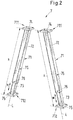
- FIG. 2 shows a perspective view of the two legs 71 of the support structure 7.
- Each leg 71 extends in the vertical plane 13 ( Fig. 5 ) from a first end 711 along a longitudinal axis L to a second end 712 and comprises an outer member 72 as well as an inner member 73 coaxially arranged in the outer member 72, wherein the inner member 73 is slidingly movable relative to the outer member 72 in direction of the longitudinal axis L for adjusting the length H of the respective leg 71 to the distance between the housing part 8 of the agitator 1 and the foundation 12.
- the movability of the inner member 73 relative to the outer member 72 is symbolically indicated by the double arrows M in Fig. 2 .
- the inner member 73 and the outer member 72 are movable relative to each other telescopically to modify the total length H of the respective leg 71.
- each of the inner members 73 and each of the outer members 72 have a square cross section in a section perpendicular to the longitudinal axis L of the respective leg 71.
- the inner members 73 and the outer members 72 are all designed as hollow rod shaped members and manufactured from a metallic material, for example any kind of steel like a carbon steel or a stainless steel.
- the square cross sectional area of the respective inner member 73 is smaller than the square cross section of the corresponding outer member 72, in which the respective inner member 73 moves, to such an amount that the inner member 73 can easily slide with respect to the outer member 73.
- quadratic cross section of the inner members 73 and the outer members 72 is a preferred measure from the point of view of stability and procurement, it goes without saying that other cross sections perpendicular to the longitudinal axis L are also possible, for example a rectangular cross section, a circular cross section, a triangular cross section or the like.
- each leg 71 comprises a mounting plate 74 at the first end 711 and a base plate 75 at the second end 712 of the respective leg 71.
- each mounting plate 74 and each base plate 75 is designed as a rectangular, particularly a quadratic, plate.
- the base plate 75 extends in a horizontal plane, i.e. parallel to the foundation 12 and preferably comprises a plurality of holes - here four holes, one in each corner - for fixing the leg 71 to the foundation 12.
- the base plate 75 may be secured to the foundation 12 by means of screws or bolts extending through the holes in the base plate 74.
- each mounting plate 74 extends in a plane which is parallel to the rotation axis A of the agitator 1. If the agitator 1 is horizontally mounted each mounting plate 74 extends in a horizontal plane 14 ( Fig. 5 ).
- the mounting plate 74 is intended for firmly connecting the leg 71 to the housing part 8 of the agitator 1.
- Fig. 3 shows an enlarged perspective view from the underside on the connection between the legs 71 and the housing part 8 of the embodiment shown in Fig. 1
- Fig. 4 shows an enlarged perspective view from the upside on said connection.
- the agitator 1 comprises a connecting part 9 that is fixed to the housing part 8 of the agitator 1.
- the surface of the connecting part 9 abutting the housing part 8 has a contour that matches the outer contour of the housing part 8, i.e. the shape of the surface of the connecting part 9 that contacts the housing part 8 is adapted to the outer surface of the housing part 8 to realize a large surface contact between the housing part 8 and the connecting part 9. This measure ensures a stable support and a uniform distribution of the load.
- the surface of the connecting part 9 being in contact with the housing part 8 is a curved surface wherein the curvature follows the curvature of the housing part 8.
- the connecting part 9 may be formed integrally with the housing part 8 or it may be a separate part that is firmly connected to the housing part 8 by any appropriate means, for example by welding.
- the surface of the connecting part 9 facing away from the housing part 8 is designed as a plane surface extending in the horizontal plane 14.
- the connecting part 9 is designed for being connected to the legs 71 in a detachable manner.
- the plan surface of the connecting part 9 facing away from the housing part 8 is provided with a plurality of threaded holes 91 ( Fig. 4 ) for receiving screws 79 which fix the legs 71 to the connecting part 9 in a detachable manner.
- each leg 71 being designed as a quadratic plate is provided with a plurality of holes - here four holes, one in each corner of the mounting plate 74.
- the connecting part has eight threaded holes 91 for receiving the screws 79 that fix the legs 71 with respect to the connecting member 9.
- the holes 91 that receive the screws 79 are designed as plane bores or holes, i.e. without a thread.
- the screws 79 are then extending completely through said holes and secured respectively with a nut that is screwed to the end of the screw protruding from the upper surface of the connecting member 9.
- the outer member 72 comprises at least one pre-drilled hole 76 ( Fig. 2 ) preferably extending perpendicular to the longitudinal axis L of the leg 71.
- each pre-drilled hole 76 extends through both opposing side faces of the respective outer member 72.
- the pre-drilled hole 76 is intended for receiving a securing element (not shown), for example a screw and a nut.
- the pre-drilled hole 76 is used as a guide for drilling a perforation extending through the entire leg 71, i.e. through both the outer member 72 and the inner member 73.
- the perforation can extend in a horizontal direction or in a direction perpendicular to the longitudinal axis L.
- the securing element for example the screw is inserted into the perforation and a nut is screwed to the end of the screw that extends through the perforation thereby firmly fixing the inner member 73 with respect to the outer member 72.
- the outer member 72 has a plurality of pre-drilled holes 76.
- This provides the advantage that depending on the adjusted length H of the leg 71, i.e. how much the inner member 73 has been moved out of the outer member 72 an appropriate location may be chosen for providing the perforation for the securing element.
- a plurality of pre-drilled holes 76 enables the use of more than one, preferably two, securing elements, e.g. two screws and two nuts, for making the fixation of the outer member 72 relative to the inner member 73 even more stable, safe and reliable.
- the outer member 72 has four side faces each extending in the direction of the longitudinal axis L.
- at least two different and abutting side faces of the outer member 72 are provided with at least one pre-drilled hole 76.
- two securing means e.g. screws and nuts that extend perpendicular with respect to each other.
- This provides a very stable and reliable fixation of the inner member 73 with respect to the outer member 72.
- the horizontal plane 14 in which the mounting plate 74 extends and the longitudinal axis L of the leg 71 include a mounting angle ⁇ that is different from 90 degree.
- the mounting angle ⁇ has the same value for each leg 71.
- the preferred range for the mounting angle ⁇ is from 60° to 85°. Even more preferred the mounting angle ⁇ is between 70° and 80°.
- the two legs 71 are arranged symmetrically with respect to the vertical direction V, i.e. each leg 71 includes the same angle with the vertical direction V.
- the resulting angle between the two legs 71 is between 30° and 60°.
- the resulting angle between the two legs 71 is between 20° and 40°.
- a preferred method for mounting the agitator 1 to the wall 10 of the vessel 11 comprises the following steps: the mounting flange 5 of the agitator 1 is fastened to the wall 10 of the vessel 11. If not yet done the leg 71 or the legs 71 is/are connected and fixed to the connecting part 9. The inner member 73 is slidingly moved with respect to the outer member 72. This movement can be caused by gravity only, i.e. the inner member 73 is released with respect to the outer member 72 and drops down to the foundation 12. Thus, each leg 71 is adjusted or extended to the correct length H by moving the inner member 73 of the leg 71 relative to the coaxially arranged outer member 72 of the leg 71 along the longitudinal axis L of the leg 71 until the base plate 75 of the leg 71 contacts the foundation 12. After that the inner member 73 is fixed to the outer member 72 of the respective leg 71, for example in a manner as described hereinbefore.
- Fig. 6 shows a plan view from the backside of a second embodiment of a rotary machine 1 according to the invention, mounted to the wall 10 of a vessel 11 and designed as an agitator 1.
- the reference numerals have the same meaning as already explained in connection with the first embodiment. It shall be understood that all the explanations given hereinbefore are also valid for the second embodiment in the same manner or in an analogous manner.
- the support structure 7 comprises only one leg 71.
- the leg 71 is extending in the vertical direction V, i.e. the longitudinal axis L of the leg 71 coincides with the vertical direction V.
- the mounting plate 74 is arranged centrally with respect to the connecting part 9 to provide the most effective support. If the agitator 1 is horizontally mounted the mounting plate 74 extends in the horizontal plane 14. Thus, the mounting angle ⁇ between the horizontal plane 14 in which the mounting plate 74 extends and the longitudinal axis L of the leg 71 equals 90 degree.
- the agitator 1 is designed for an oblique mounting to the wall of a vessel, i.e. the rotation axis A or the drive shaft 3, respectively, of the mounted agitator 1 includes an angle with the horizontal direction that is different from zero degree and different from 90 degree.
- the mounting plate 74 is extending in a plane that is parallel to the rotation axis A such that there is a plane contact surface between the mounting plate 74 and the connecting part 9.
- the leg 71 is again extending in the vertical direction V.
Landscapes
- Chemical & Material Sciences (AREA)
- Chemical Kinetics & Catalysis (AREA)
- Engineering & Computer Science (AREA)
- Mechanical Engineering (AREA)
- General Engineering & Computer Science (AREA)
- Aviation & Aerospace Engineering (AREA)
- Mixers Of The Rotary Stirring Type (AREA)
- Accessories For Mixers (AREA)
- Structures Of Non-Positive Displacement Pumps (AREA)
Abstract
Description
- The invention relates to a rotary machine for mixing, pumping or agitating a fluid and to a method of mounting a rotary machine according to the preamble of the independent claim of the respective category.
- Rotary machines for mixing, pumping or agitating one fluid or several fluids like for example agitators are used in many different industrial processes for mixing or agitating a process fluid, e.g. a liquid or a liquid containing solids.
- In most applications the process fluid is contained in a tank or a tower or another vessel and the agitator is mounted to a wall or the bottom or the cover of said vessel. Amongst the wide range of industries where agitators are used is for example the pulp and paper industry. Here, agitators are used for example for dilution, mixing or bleaching processes.
- Basically a rotary machine like an agitator comprises an impeller or propeller for acting on the fluid, a shaft which is connected at its one end to the impeller and at its other end to a drive unit for rotating the shaft with the impeller. The drive unit usually has a motor and a coupling for connecting the motor with the shaft, wherein the coupling comprises a belt drive or a gear box or any other suited transmission device.
- Typically the drive unit is arranged outside of the vessel and the shaft with the impeller is located inside the vessel for agitating the process fluid. There are known both top-mounted and side-mounted agitators. Top-mounted agitators are usually mounted to the cover or the top part of the tower or the vessel with the shaft of the agitator extending vertically. Side-mounted agitators are usually mounted to a side wall of the tower or the vessel with the shaft extending horizontally. Examples for both types of agitators are those which are sold by the applicant under the brands SALOMIX ™ and SCABA ™.
- Especially for side-mounted rotary machines like side-mounted pumps or side-mounted agitators there is often the need to provide additional support to the machine. Usually such machines comprise a mounting flange for fastening the rotary machine to the wall of a vessel. Since these parts which are outside the vessel, e.g. the drive unit and the coupling with the transmission device, have a considerable weight putting a very high load on the mounting flange it is known to provide a support structure that is connected to a housing part of the rotary machine located outside the vessel and extends therefrom to the ground or a suited foundation to support the rotary machine.
- When the rotary machine is delivered to the location where it shall be installed the distance between the mounted rotary machine and the floor or the foundation is in most cases not yet known or not yet exactly known. Therefore, after the fastening of the rotary machine to the wall of the vessel by means of the mounting flange said distance has to be determined in an exact manner. After that, the legs of the support structure extending from the rotary machine to the floor have to be cut to the right length and the mounting plate of the support structure that abuts the rotary machine and/or the base of the support structure that abuts the floor is/are then welded to the respective support leg. This is quite a laborious and time-consuming process.
- Starting from this state of the art it is therefore an object of the invention to propose a rotary machine for mixing, pumping or agitating a fluid that can be installed and supported in a simpler and less time-consuming manner. In addition it is an object of the invention to propose a method of mounting such a rotary machine to a wall of a vessel which is easier and less time-consuming than the methods known from the state of the art.
- The subject matters of the invention satisfying these objects are characterized by the features of the independent claim of the respective category.
- Thus, according to the invention a rotary machine for mixing, pumping or agitating a fluid is proposed comprising an impeller for acting on the fluid, a drive unit for rotating the impeller around a rotation axis, a drive shaft connecting the impeller with the drive unit, a mounting flange for fastening the rotary machine to a wall of a vessel, and a support structure for supporting the rotary machine, wherein the support structure comprises at least one leg, each leg extending in a vertical plane from a first end along a longitudinal axis to a second end, wherein each leg comprises an outer member and an inner member coaxially arranged in the outer member, and wherein the inner member is slidingly movable relative to the outer member for adjusting the length of the respective leg.
- By providing the rotary machine with a support structure having at least one leg with an adjustable length the mounting of the rotary machine to the wall of the vessel becomes much easier and considerably less time-consuming. Due to the telescopic design of the leg or the legs the length of each leg may be adjusted very easily to the respective environment or to the given spatial circumstances. After the rotary machine has been mounted to the wall of the vessel by means of the mounting flange the inner member of each leg is moved with respect to the respective outer member until the second end of the leg contacts the floor or a foundation. After that the outer member is fixed relative to the inner member thus providing a firm support for the rotary machine. There is no need for additional cutting, welding or similar processes. It is an additional advantage that the same support structure may be used if the rotary machine is moved to a different location or changes in the distance from the rotary machine to the foundation require an adaption of the support structure. With the rotary machine according to the invention the leg or the legs of the support structure is/are easily adjustable to any new location or to changes in the distance between the rotary machine and the foundation.
- According to a preferred embodiment each leg comprises a mounting plate at the first end of the respective leg for mounting the leg to a housing part of the rotary machine, and a base plate at the second end of the respective leg for connecting the leg to a foundation or the ground. The mounting plate renders possible an easy detachment and an easy fixing of the respective leg to the housing part of the rotary machine. By means of the base plate the respective leg may be firmly connected, for example by screws, to the foundation or to the floor.
- It is an advantageous measure when each outer member comprises at least one pre-drilled hole for receiving a securing element. As soon as the leg is adjusted to the correct length the pre-drilled hole in the outer member may be used to drill a perforation through the entire leg in a horizontal direction. After that a securing element, e.g. a screw, is inserted into the perforation from one side of the leg until its end exits the opposing wall of the leg where a nut is screwed on this end thus safely fixing the inner member with respect to the outer member.
- In one preferred embodiment a plane in which the mounting plate extends and the longitudinal axis of the leg include a mounting angle that is different from 90 degree for each leg. This provides an especially stable support.
- In another preferred embodiment the support structure comprises only a single leg. In such an embodiment the plane in which the mounting plate extends and the longitudinal axis of the leg include a mounting angle that is 90 degree. This provides an especially stable support.
- From a practical point of view it is preferred that each outer member and each inner member has a rectangular cross section, preferably a square cross section, in a section perpendicular to the longitudinal axis of the respective leg.
- Having a rectangular cross section the outer member of each leg has four side faces. It is preferred that two different and abutting side faces are each provided with at least one pre-drilled hole. This measure results in a high flexibility regarding a very simple and easy fixation of the inner member with respect to the outer member.
- According to a preferred embodiment the rotary machine has two legs, wherein the mounting angle for each leg is between 60° and 85°, preferably between 70° and 80°.
- According to a further advantageous measure the rotary machine has a connecting part being fixed to the housing part of the rotary machine and designed for being connected to each leg in a detachable manner. The connecting member may be designed in such a manner that it matches the outer shape of the housing part thus providing an optimal support.
- Preferably each mounting plate is mountable to the connecting part by means of screws. This enables an easy fixing and detaching of the respective leg.
- According to a preferred application the rotary machine is designed as an agitator for mixing or agitating a fluid.
- Preferably the agitator is designed for being horizontally mounted to the wall of the vessel. But it is also possible that the agitator is designed for an oblique mounting to the wall of the vessel, i.e. the rotation axis of the mounted agitator includes an angle with the horizontal direction that is different from zero degree.
- In addition, according to another aspect of the invention a method of mounting a rotary machine for mixing, pumping or agitating a fluid to a wall of a vessel is proposed, comprising the steps of fastening a mounting flange of the rotary machine to the wall of the vessel, and mounting at least one leg of a support structure to a housing part of the rotary machine, extending each leg by moving an inner member of the leg relative to a coaxially arranged outer member of the leg along a longitudinal axis of the leg until a base plate of the leg contacts a foundation, and fixing the inner member to the outer member of the respective leg.
- This method enables a much easier and considerably less time-consuming mounting of the rotary machine to the wall of a vessel.
- According to a preferred embodiment the step of fixing the inner member to the outer member of the respective leg comprises: selecting one of a plurality of pre-drilled holes in the outer member, using the selected hole for generating a perforation extending through the entire leg, preferably in a horizontal direction or in a direction perpendicular to the longitudinal axis, inserting a securing element into the perforation for fixing the inner member to the outer member.
- From a practical point of view and in order to provide a very good support it is preferred, when exactly two legs are used for supporting the rotary machine.
- The method according to the invention is in particular suited when the rotary machine is an agitator, in particular an agitator for being horizontally mounted.
- Further advantageous measures and embodiments of the invention will become apparent from the dependent claims.
- The invention will be explained in more detail hereinafter with reference to the drawings. There are shown in a schematic representation, partially in cross-section:
- Fig. 1:
- a perspective view of a first embodiment of a rotary machine according to the invention and designed as an agitator,
- Fig. 2:
- a perspective view of the legs of the support structure,
- Fig. 3:
- an enlarged perspective view from the underside on the connecting part of the embodiment shown in
Fig. 1 , - Fig. 4:
- an enlarged perspective view from the upside on the connecting part of the embodiment shown in
Fig. 1 , - Fig. 5:
- a schematic sketch showing a plan view from the backside, and
- Fig. 6:
- a plan view from the backside of a second embodiment of a rotary machine according to the invention, mounted to a wall of a vessel and designed as an agitator.
- In the following description of preferred embodiments reference is made to an agitator as an example for a rotary machine according to the invention. Although this is in practice an important embodiment of the invention it has to be understood that the invention is not restricted to such embodiments as an agitator. The rotary machine according to the invention may also be designed as any other type of a rotary machine for mixing, pumping or agitating fluids, wherein the rotary machine is intended for being mounted to a wall of a vessel. In particular, the rotary machine may also be a pump.
-
Fig. 1 shows a perspective view of a first embodiment of a rotary machine according to the invention. This first embodiment is designed as an agitator which is designated in its entity withreference numeral 1. For the sake of a better understanding, firstly the general setup of an agitator will be explained referring toFig. 1 . Theagitator 1 comprises animpeller 2 having a hub and three blades 21 mounted to the hub for acting on a fluid. - The hub of the
impeller 2 is connected to an end of adrive shaft 3. The other end of thedrive shaft 3 is operatively connected to a drive unit 4 for rotating thedrive shaft 3 and theimpeller 2 connected therewith around a rotation axis A. The drive unit 4 comprises amotor 41, for example anelectric motor 41, and acoupling 42 for operatively connecting themotor 41 with thedrive shaft 3. - The
coupling 42 shown inFig. 1 has a belt drive for connecting themotor 41 to thedrive shaft 3. It goes without saying that the invention is not restricted to such a belt drive. The drive unit 4 of theagitator 1 may also be designed with anyother coupling 42 between themotor 41 and thedrive shaft 3 known in the art, for example with a gear box or any other suited transmission device. In addition, the relative arrangement of themotor 41, thecoupling 42 and thedrive shaft 3 shown inFig. 1 shall be understood exemplary. There are many other arrangements known in the art that are also suited for theagitator 1. - The
agitator 1 shown inFig. 1 is designed as a side-mountedagitator 1 and designed for being mounted in particular horizontally to a wall of a vessel, a tank, a tower, a container or any other receptacle, i.e. thedrive shaft 3 is extending horizontally in the usual orientation of use of theagitator 1. Although this is a preferred embodiment for theagitator 1, the invention is not restricted to side-mounted or horizontal agitators. Theagitator 1 may also be designed for example as a top-mounted or vertical agitator, i.e. with the drive shaft extending vertically in the usual orientation of use. Furthermore, it is also possible that theagitator 1 is designed for an oblique mounting to the wall of a vessel, i.e. the rotation axis A or thedrive shaft 3, respectively, of the mounted agitator includes an angle with the horizontal direction that is different from zero degree and different from 90 degree. - For a better understanding
Fig. 5 shows a schematic sketch corresponding to a plan view from the backside of theagitator 1, wherein the backside is the side facing away from theimpeller 2. In the representation ofFig. 5 theagitator 1 is fastened to awall 10 of avessel 11, wherein thevessel 11 may be any type of a receptacle, e.g. a tower or a tank. - The side-mounted
agitator 1 has a mounting flange 5 (seeFig. 1 ) for fastening theagitator 1 to thewall 10 of thevessel 11. The mountingflange 5 surrounds thedrive shaft 3 concentrically and comprises several bores for receiving screws or bolts for fastening theagitator 1 to thewall 10 in a manner which is as such known in the art. When theagitator 1 is mounted to thewall 10, the mountingflange 5, theimpeller 2 and the part of theshaft drive 3 between the mountingflange 5 and theimpeller 2 are located within thevessel 11, containing the process fluid to be agitated or mixed or pumped by theimpeller 2. Further details of theagitator 1 such as seals and bearings are well known to the skilled person and therefore will not be described in more detail. - In order to support the
agitator 1 and to unload the mountingflange 5 from the weight especially of the drive unit 4 theagitator 1 comprises asupport structure 7 extending between ahousing part 8 of theagitator 1 and afoundation 12 or thefloor 12. Thefoundation 12 may be the floor or the ground of the location where theagitator 1 is installed or a solid stand or baseplate which is able to bear the weight of theagitator 1 transferred to it by thesupport structure 7. - In the first embodiment the
support structure 7 comprises a plurality of legs 71 - in this embodiment exactly two legs 71 - each leg extending in a vertical plane 13 (Fig. 5 ). Avertical plane 13 shall be understood as a plane that is perpendicular to the earth's surface, i.e. a plane extending in the direction of gravity. A horizontal plane shall be understood as a plane that is parallel to the earth's surface, i.e. a plane extending perpendicular to the direction of gravity. In the same manner, 'vertical' denotes a direction that is parallel or equal to the direction of gravity and 'horizontal' denotes a direction that is perpendicular to the direction of gravity. - For a better understanding
Fig. 2 shows a perspective view of the twolegs 71 of thesupport structure 7. Eachleg 71 extends in the vertical plane 13 (Fig. 5 ) from afirst end 711 along a longitudinal axis L to asecond end 712 and comprises anouter member 72 as well as aninner member 73 coaxially arranged in theouter member 72, wherein theinner member 73 is slidingly movable relative to theouter member 72 in direction of the longitudinal axis L for adjusting the length H of therespective leg 71 to the distance between thehousing part 8 of theagitator 1 and thefoundation 12. The movability of theinner member 73 relative to theouter member 72 is symbolically indicated by the double arrows M inFig. 2 . - The
inner member 73 and theouter member 72 are movable relative to each other telescopically to modify the total length H of therespective leg 71. In the embodiment shown inFig. 1 andFig. 2 each of theinner members 73 and each of theouter members 72 have a square cross section in a section perpendicular to the longitudinal axis L of therespective leg 71. Preferably theinner members 73 and theouter members 72 are all designed as hollow rod shaped members and manufactured from a metallic material, for example any kind of steel like a carbon steel or a stainless steel. The square cross sectional area of the respectiveinner member 73 is smaller than the square cross section of the correspondingouter member 72, in which the respectiveinner member 73 moves, to such an amount that theinner member 73 can easily slide with respect to theouter member 73. - Although the quadratic cross section of the
inner members 73 and theouter members 72 is a preferred measure from the point of view of stability and procurement, it goes without saying that other cross sections perpendicular to the longitudinal axis L are also possible, for example a rectangular cross section, a circular cross section, a triangular cross section or the like. - As can be seen for example in
Fig. 2 , eachleg 71 comprises a mountingplate 74 at thefirst end 711 and abase plate 75 at thesecond end 712 of therespective leg 71. Preferably, each mountingplate 74 and eachbase plate 75 is designed as a rectangular, particularly a quadratic, plate. - In the mounted state the
base plate 75 extends in a horizontal plane, i.e. parallel to thefoundation 12 and preferably comprises a plurality of holes - here four holes, one in each corner - for fixing theleg 71 to thefoundation 12. After the length H of therespective leg 71 has been adjusted correctly thebase plate 75 may be secured to thefoundation 12 by means of screws or bolts extending through the holes in thebase plate 74. - In the mounted state each mounting
plate 74 extends in a plane which is parallel to the rotation axis A of theagitator 1. If theagitator 1 is horizontally mounted each mountingplate 74 extends in a horizontal plane 14 (Fig. 5 ). - The mounting
plate 74 is intended for firmly connecting theleg 71 to thehousing part 8 of theagitator 1. Referring in particular toFig. 3 and Fig. 4 a preferred connection of thelegs 71 with thehousing part 8 is now described in more detail.Fig. 3 shows an enlarged perspective view from the underside on the connection between thelegs 71 and thehousing part 8 of the embodiment shown inFig. 1 , andFig. 4 shows an enlarged perspective view from the upside on said connection. - The
agitator 1 comprises a connectingpart 9 that is fixed to thehousing part 8 of theagitator 1. The surface of the connectingpart 9 abutting thehousing part 8 has a contour that matches the outer contour of thehousing part 8, i.e. the shape of the surface of the connectingpart 9 that contacts thehousing part 8 is adapted to the outer surface of thehousing part 8 to realize a large surface contact between thehousing part 8 and the connectingpart 9. This measure ensures a stable support and a uniform distribution of the load. In the embodiment shown inFig. 3 and Fig. 4 the surface of the connectingpart 9 being in contact with thehousing part 8 is a curved surface wherein the curvature follows the curvature of thehousing part 8. - The connecting
part 9 may be formed integrally with thehousing part 8 or it may be a separate part that is firmly connected to thehousing part 8 by any appropriate means, for example by welding. - The surface of the connecting
part 9 facing away from thehousing part 8 is designed as a plane surface extending in thehorizontal plane 14. The connectingpart 9 is designed for being connected to thelegs 71 in a detachable manner. In the described embodiment of theagitator 1 the plan surface of the connectingpart 9 facing away from thehousing part 8 is provided with a plurality of threaded holes 91 (Fig. 4 ) for receivingscrews 79 which fix thelegs 71 to the connectingpart 9 in a detachable manner. - The mounting
plate 74 of eachleg 71 being designed as a quadratic plate is provided with a plurality of holes - here four holes, one in each corner of the mountingplate 74. According to this the connecting part has eight threadedholes 91 for receiving thescrews 79 that fix thelegs 71 with respect to the connectingmember 9. - For mounting the
legs 71 to the connectingmember 9 the respective mountingplate 74 of theleg 71 is put to the connectingmember 9, thescrews 79 are inserted into the holes in the mountingplate 74 and screwed into the threadedholes 91 of the connectingmember 9 thus firmly connecting therespective leg 71 with the connectingmember 9. - As an alternative it is also possible to design the
holes 91 that receive thescrews 79 as plane bores or holes, i.e. without a thread. Thescrews 79 are then extending completely through said holes and secured respectively with a nut that is screwed to the end of the screw protruding from the upper surface of the connectingmember 9. - After the
leg 71 has been adjusted to the appropriate length H by telescopically moving theinner member 73 with respect to theouter member 72 theinner member 73 has to be fixed with respect to theouter member 72 to prevent any further relative movement between theinner member 73 and theouter member 72. To facilitate the fixation of theouter member 72 with respect to theinner member 73 it is advantageous when theouter member 72 comprises at least one pre-drilled hole 76 (Fig. 2 ) preferably extending perpendicular to the longitudinal axis L of theleg 71. InFig. 2 eachpre-drilled hole 76 extends through both opposing side faces of the respectiveouter member 72. Thepre-drilled hole 76 is intended for receiving a securing element (not shown), for example a screw and a nut. For fixing theinner member 73 with respect to theouter member 72 thepre-drilled hole 76 is used as a guide for drilling a perforation extending through theentire leg 71, i.e. through both theouter member 72 and theinner member 73. The perforation can extend in a horizontal direction or in a direction perpendicular to the longitudinal axis L. After the perforation has been generated the securing element, for example the screw is inserted into the perforation and a nut is screwed to the end of the screw that extends through the perforation thereby firmly fixing theinner member 73 with respect to theouter member 72. - Preferably the
outer member 72 has a plurality ofpre-drilled holes 76. This provides the advantage that depending on the adjusted length H of theleg 71, i.e. how much theinner member 73 has been moved out of theouter member 72 an appropriate location may be chosen for providing the perforation for the securing element. In addition, a plurality ofpre-drilled holes 76 enables the use of more than one, preferably two, securing elements, e.g. two screws and two nuts, for making the fixation of theouter member 72 relative to theinner member 73 even more stable, safe and reliable. - When the
leg 71 has a rectangular or a square cross section perpendicular to its longitudinal axis L, as described hereinbefore, theouter member 72 has four side faces each extending in the direction of the longitudinal axis L. As can be seen inFig. 1 andFig. 2 , for this design it is preferred that at least two different and abutting side faces of theouter member 72 are provided with at least onepre-drilled hole 76. Thereby it is possible to use two securing means, e.g. screws and nuts that extend perpendicular with respect to each other. This provides a very stable and reliable fixation of theinner member 73 with respect to theouter member 72. In addition, depending on the location where theagitator 1 is mounted, it might be difficult to access all side faces of theouter member 72 easily. In such cases one can choose the pre-drilled hole or holes 76 on that side face that is accessible the easiest. - In view of an optimal and stable support for the first embodiment of the
agitator 1 it is preferred when the horizontal plane 14 (Fig. 5 ) in which the mountingplate 74 extends and the longitudinal axis L of theleg 71 include a mounting angle α that is different from 90 degree. In the described embodiment with exactly twolegs 71 the mounting angle α has the same value for eachleg 71. The preferred range for the mounting angle α is from 60° to 85°. Even more preferred the mounting angle α is between 70° and 80°. Preferably and as it is show inFig. 5 the twolegs 71 are arranged symmetrically with respect to the vertical direction V, i.e. eachleg 71 includes the same angle with the vertical direction V. For the preferred range of the mounting angle α the resulting angle between the twolegs 71 is between 30° and 60°. For the more preferred range of the mounting angle α between 70° and 80° the resulting angle between the twolegs 71 is between 20° and 40°. - A preferred method for mounting the
agitator 1 to thewall 10 of thevessel 11 comprises the following steps: the mountingflange 5 of theagitator 1 is fastened to thewall 10 of thevessel 11. If not yet done theleg 71 or thelegs 71 is/are connected and fixed to the connectingpart 9. Theinner member 73 is slidingly moved with respect to theouter member 72. This movement can be caused by gravity only, i.e. theinner member 73 is released with respect to theouter member 72 and drops down to thefoundation 12. Thus, eachleg 71 is adjusted or extended to the correct length H by moving theinner member 73 of theleg 71 relative to the coaxially arrangedouter member 72 of theleg 71 along the longitudinal axis L of theleg 71 until thebase plate 75 of theleg 71 contacts thefoundation 12. After that theinner member 73 is fixed to theouter member 72 of therespective leg 71, for example in a manner as described hereinbefore. -
Fig. 6 shows a plan view from the backside of a second embodiment of arotary machine 1 according to the invention, mounted to thewall 10 of avessel 11 and designed as anagitator 1. In the following description only the differences to the first embodiment will be explained. In particular, the reference numerals have the same meaning as already explained in connection with the first embodiment. It shall be understood that all the explanations given hereinbefore are also valid for the second embodiment in the same manner or in an analogous manner. - In the second embodiment the
support structure 7 comprises only oneleg 71. Theleg 71 is extending in the vertical direction V, i.e. the longitudinal axis L of theleg 71 coincides with the vertical direction V. The mountingplate 74 is arranged centrally with respect to the connectingpart 9 to provide the most effective support. If theagitator 1 is horizontally mounted the mountingplate 74 extends in thehorizontal plane 14. Thus, the mounting angle α between thehorizontal plane 14 in which the mountingplate 74 extends and the longitudinal axis L of theleg 71 equals 90 degree. - Also for the second embodiment it is possible that the
agitator 1 is designed for an oblique mounting to the wall of a vessel, i.e. the rotation axis A or thedrive shaft 3, respectively, of the mountedagitator 1 includes an angle with the horizontal direction that is different from zero degree and different from 90 degree. In this case the mountingplate 74 is extending in a plane that is parallel to the rotation axis A such that there is a plane contact surface between the mountingplate 74 and the connectingpart 9. Of course, theleg 71 is again extending in the vertical direction V.
Claims (15)
- A rotary machine for mixing, pumping or agitating a fluid comprising an impeller (2) for acting on the fluid, a drive unit (4) for rotating the impeller (2) around a rotation axis (A), a drive shaft (3) connecting the impeller (2) with the drive unit (4), a mounting flange (5) for fastening the rotary machine (1) to a wall (10) of a vessel (11), and a support structure (7) for supporting the rotary machine, wherein the support structure (7) comprises at least one leg (71), each leg (71) extending in a vertical plane (13) from a first end (711) along a longitudinal axis (L) to a second end (712), characterized in that each leg (71) comprises an outer member (72) and an inner member (73) coaxially arranged in the outer member (72), wherein the inner member (73) is slidingly movable relative to the outer member (72) for adjusting the length (H) of the respective leg (71).
- A rotary machine in accordance with claim 1, wherein each leg (71) comprises a mounting plate (74) at the first end (711) of the respective leg (71) for mounting the leg (71) to a housing part (8) of the rotary machine (1), and a base plate (75) at the second end (712) of the respective leg (71) for connecting the leg (71) to a foundation (12) or the ground (12).
- A rotary machine in accordance with anyone of the preceding claims, wherein each outer member (72) comprises at least one pre-drilled hole (76) for receiving a securing element.
- A rotary machine in accordance with anyone of the preceding claims, wherein a plane (14) in which the mounting plate (74) extends and the longitudinal axis (L) of the leg (71) include a mounting angle (α) that is different from 90 degree for each leg (71).
- A rotary machine in accordance with anyone of the preceding claims, wherein each outer member (72) and each inner member (73) has a rectangular cross section, preferably a square cross section, in a section perpendicular to the longitudinal axis (L) of the respective leg (71).
- A rotary machine in accordance with claim 5, wherein the outer member (72) of each leg (71) has four side faces and wherein two different and abutting side faces are each provided with at least one pre-drilled hole (76).
- A rotary machine in accordance with anyone of the preceding claims having two legs (71), wherein the mounting angle (α) for each leg (7) is between 60° and 85°, preferably between 70° and 80°.
- A rotary machine in accordance with anyone of the preceding claims having a connecting part (9) being fixed to the housing part (8) of the rotary machine and designed for being connected to each leg (71) in a detachable manner.
- A rotary machine in accordance with claim 8 wherein each mounting plate (74) is mountable to the connecting part (9) by means of screws (79).
- A rotary machine in accordance with anyone of the preceding claims designed as an agitator (1) for mixing or agitating a fluid.
- A rotary machine in accordance with claim 10, wherein the agitator (1) is designed for being horizontally mounted to the wall (10) of the vessel (11).
- A method of mounting a rotary machine for mixing, pumping or agitating a fluid to a wall (10) of a vessel (11) comprising the steps of fastening a mounting flange (5) of the rotary machine to the wall (10) of the vessel (11), and mounting at least one leg (71) of a support structure (7) to a housing part (8) of the rotary machine (1), characterized by extending each leg (71) by moving an inner member (73) of the leg (71) relative to a coaxially arranged outer member (72) of the leg (7) along a longitudinal axis (L) of the leg (71) until a base plate (75) of the leg (71) contacts a foundation (12), and fixing the inner member (73) to the outer member (72) of the respective leg (71).
- A method in accordance with claim 12, wherein the step of fixing the inner member (73) to the outer member (72) of the respective leg (71) comprises:selecting one of a plurality of pre-drilled holes (76) in the outer member (73), using the selected hole (76) for generating a perforation extending through the entire leg (71), inserting a securing element into the perforation for fixing the inner member (73) to the outer member (72).
- A method in accordance with claim 12 or claim 13 wherein exactly two legs (71) are used for supporting the rotary machine.
- A method in accordance with anyone of claims 12 to 14 wherein the rotary machine is an agitator (1), in particular an agitator (1) for being horizontally mounted.
Applications Claiming Priority (1)
| Application Number | Priority Date | Filing Date | Title |
|---|---|---|---|
| EP16164640 | 2016-04-11 |
Publications (2)
| Publication Number | Publication Date |
|---|---|
| EP3231503A1 true EP3231503A1 (en) | 2017-10-18 |
| EP3231503B1 EP3231503B1 (en) | 2023-05-24 |
Family
ID=55754117
Family Applications (1)
| Application Number | Title | Priority Date | Filing Date |
|---|---|---|---|
| EP17160300.4A Active EP3231503B1 (en) | 2016-04-11 | 2017-03-10 | A rotary machine for mixing, pumping or agitating a fluid and a method of mounting |
Country Status (5)
| Country | Link |
|---|---|
| US (1) | US11339803B2 (en) |
| EP (1) | EP3231503B1 (en) |
| CN (1) | CN107281946A (en) |
| FI (1) | FI3231503T3 (en) |
| RU (1) | RU2727490C2 (en) |
Families Citing this family (1)
| Publication number | Priority date | Publication date | Assignee | Title |
|---|---|---|---|---|
| CN121018725B (en) * | 2025-10-31 | 2026-03-24 | 景德镇水流星陶瓷文化传播有限公司 | A potter's wheel for producing ceramic handicrafts |
Citations (2)
| Publication number | Priority date | Publication date | Assignee | Title |
|---|---|---|---|---|
| DE3417204A1 (en) * | 1983-12-07 | 1985-06-20 | Gottfried Salzburg Perdolt | Agitator |
| WO2003028870A1 (en) * | 2001-09-24 | 2003-04-10 | Ksb Aktiengesellschaft | Mixing or agitating device for containers |
Family Cites Families (13)
| Publication number | Priority date | Publication date | Assignee | Title |
|---|---|---|---|---|
| US1399699A (en) * | 1920-07-01 | 1921-12-06 | Donauer Max | Liquid-agitating mechanism |
| SU10787A1 (en) * | 1928-07-21 | 1929-07-31 | В.В. Писаренко | Machine for mixing paints and other materials |
| US2096597A (en) * | 1937-01-21 | 1937-10-19 | Mixing Equipment Company Inc | Mixer drive |
| US2194027A (en) * | 1938-11-14 | 1940-03-19 | William J Mcdonald | Carpenter's horse |
| US3120948A (en) * | 1962-03-15 | 1964-02-11 | King Of Prussia Res And Dev Co | Variable angle mixer drive |
| US4640386A (en) * | 1986-02-14 | 1987-02-03 | Hall James W | Folding utility horse |
| US4776545A (en) * | 1986-08-05 | 1988-10-11 | Ryobi Ltd. | Bench stand |
| US5118199A (en) * | 1991-04-03 | 1992-06-02 | General Signal Corporation | Side entry mixer apparatus |
| RU2083095C1 (en) * | 1994-10-13 | 1997-07-10 | Юрий Ильич Деревцов | Apparatus for churning butter from milk raw material |
| US5954156A (en) * | 1998-08-17 | 1999-09-21 | Cooke; John E. | Adjustable saw horse |
| US8622355B2 (en) * | 2010-05-18 | 2014-01-07 | Paragon Furniture LP | Extendible leg assembly and retaining system |
| CN104147962A (en) * | 2014-08-23 | 2014-11-19 | 济南大学 | Stirrer for experiments |
| CN204525467U (en) * | 2015-03-13 | 2015-08-05 | 山东科技大学 | A kind of manipulator for bearing outer ring punching technology |
-
2017
- 2017-03-10 FI FIEP17160300.4T patent/FI3231503T3/en active
- 2017-03-10 EP EP17160300.4A patent/EP3231503B1/en active Active
- 2017-03-14 CN CN201710150167.XA patent/CN107281946A/en active Pending
- 2017-03-24 RU RU2017109776A patent/RU2727490C2/en active
- 2017-03-24 US US15/468,617 patent/US11339803B2/en active Active
Patent Citations (2)
| Publication number | Priority date | Publication date | Assignee | Title |
|---|---|---|---|---|
| DE3417204A1 (en) * | 1983-12-07 | 1985-06-20 | Gottfried Salzburg Perdolt | Agitator |
| WO2003028870A1 (en) * | 2001-09-24 | 2003-04-10 | Ksb Aktiengesellschaft | Mixing or agitating device for containers |
Also Published As
| Publication number | Publication date |
|---|---|
| CN107281946A (en) | 2017-10-24 |
| US11339803B2 (en) | 2022-05-24 |
| RU2727490C2 (en) | 2020-07-21 |
| FI3231503T3 (en) | 2023-08-17 |
| US20170292535A1 (en) | 2017-10-12 |
| EP3231503B1 (en) | 2023-05-24 |
| BR102017005318A8 (en) | 2022-07-05 |
| RU2017109776A3 (en) | 2020-05-14 |
| RU2017109776A (en) | 2018-09-24 |
| BR102017005318A2 (en) | 2017-11-21 |
Similar Documents
| Publication | Publication Date | Title |
|---|---|---|
| US4981367A (en) | Portable mixing apparatus | |
| FI124092B (en) | Process and plant for forming a homogeneous mixture in connection with a hydrometallurgical process | |
| EP3231503B1 (en) | A rotary machine for mixing, pumping or agitating a fluid and a method of mounting | |
| KR102097059B1 (en) | Magnetic mixing apparatus | |
| JP5413243B2 (en) | Stirring apparatus and stirring method | |
| EP2950915A1 (en) | Stirred tank reactor | |
| US4854720A (en) | Disperser apparatus with two coaxial drive shafts | |
| KR102300428B1 (en) | High-efficiency mixed magnetic impeller stirrer using sediment suppression and multiple vortices | |
| US4984899A (en) | Agitator vessel with radially conveying agitator and with at least one baffle, as well as process for the thorough mixing of liquids with the aid of this agitator vessel | |
| BR102017005318B1 (en) | ROTARY MACHINE FOR MIXING, PUMPING AND AGIRATION OF A FLUID AND METHOD OF ASSEMBLY OF SAID ROTARY MACHINE | |
| JP5062696B2 (en) | Stirrer | |
| KR102286219B1 (en) | A stirrer with a connecting structure of the axis to improve the stirring performance | |
| CN106411033A (en) | Motor base | |
| KR101377439B1 (en) | Magnetic Coupling | |
| CN206422642U (en) | Electric machine stand | |
| Dickey | Fluid mixing equipment design | |
| JP2022080043A (en) | Support system and support method | |
| CN223144936U (en) | A flotation tank scraper device | |
| CN216756088U (en) | Slurry testing stirrer | |
| JP2017051924A (en) | Agitation device | |
| JP7261331B1 (en) | Stirrer and its maintenance method | |
| CN215311612U (en) | Double-rotation coating stirrer | |
| US12606970B1 (en) | Ground reinforcement foundation piles combinable in different forms depending on ground conditions | |
| CN216005258U (en) | Automatic reagent feeding equipment for sewage treatment | |
| CN110006399A (en) | A kind of steering engine for ship installation horizontal checkout tool |
Legal Events
| Date | Code | Title | Description |
|---|---|---|---|
| PUAI | Public reference made under article 153(3) epc to a published international application that has entered the european phase |
Free format text: ORIGINAL CODE: 0009012 |
|
| STAA | Information on the status of an ep patent application or granted ep patent |
Free format text: STATUS: THE APPLICATION HAS BEEN PUBLISHED |
|
| AK | Designated contracting states |
Kind code of ref document: A1 Designated state(s): AL AT BE BG CH CY CZ DE DK EE ES FI FR GB GR HR HU IE IS IT LI LT LU LV MC MK MT NL NO PL PT RO RS SE SI SK SM TR |
|
| AX | Request for extension of the european patent |
Extension state: BA ME |
|
| STAA | Information on the status of an ep patent application or granted ep patent |
Free format text: STATUS: REQUEST FOR EXAMINATION WAS MADE |
|
| 17P | Request for examination filed |
Effective date: 20180418 |
|
| RBV | Designated contracting states (corrected) |
Designated state(s): AL AT BE BG CH CY CZ DE DK EE ES FI FR GB GR HR HU IE IS IT LI LT LU LV MC MK MT NL NO PL PT RO RS SE SI SK SM TR |
|
| STAA | Information on the status of an ep patent application or granted ep patent |
Free format text: STATUS: EXAMINATION IS IN PROGRESS |
|
| 17Q | First examination report despatched |
Effective date: 20210302 |
|
| REG | Reference to a national code |
Ref country code: DE Ref legal event code: R079 Ref document number: 602017068943 Country of ref document: DE Free format text: PREVIOUS MAIN CLASS: B01F0007060000 Ipc: B01F0027710000 |
|
| RIC1 | Information provided on ipc code assigned before grant |
Ipc: B01F 35/41 20220101ALI20221125BHEP Ipc: B01F 33/00 20220101ALI20221125BHEP Ipc: B01F 27/71 20220101AFI20221125BHEP |
|
| GRAP | Despatch of communication of intention to grant a patent |
Free format text: ORIGINAL CODE: EPIDOSNIGR1 |
|
| STAA | Information on the status of an ep patent application or granted ep patent |
Free format text: STATUS: GRANT OF PATENT IS INTENDED |
|
| INTG | Intention to grant announced |
Effective date: 20230110 |
|
| GRAS | Grant fee paid |
Free format text: ORIGINAL CODE: EPIDOSNIGR3 |
|
| GRAA | (expected) grant |
Free format text: ORIGINAL CODE: 0009210 |
|
| STAA | Information on the status of an ep patent application or granted ep patent |
Free format text: STATUS: THE PATENT HAS BEEN GRANTED |
|
| AK | Designated contracting states |
Kind code of ref document: B1 Designated state(s): AL AT BE BG CH CY CZ DE DK EE ES FI FR GB GR HR HU IE IS IT LI LT LU LV MC MK MT NL NO PL PT RO RS SE SI SK SM TR |
|
| REG | Reference to a national code |
Ref country code: GB Ref legal event code: FG4D |
|
| REG | Reference to a national code |
Ref country code: CH Ref legal event code: EP |
|
| REG | Reference to a national code |
Ref country code: DE Ref legal event code: R096 Ref document number: 602017068943 Country of ref document: DE |
|
| P01 | Opt-out of the competence of the unified patent court (upc) registered |
Effective date: 20230412 |
|
| REG | Reference to a national code |
Ref country code: AT Ref legal event code: REF Ref document number: 1569184 Country of ref document: AT Kind code of ref document: T Effective date: 20230615 |
|
| REG | Reference to a national code |
Ref country code: IE Ref legal event code: FG4D |
|
| REG | Reference to a national code |
Ref country code: FI Ref legal event code: FGE |
|
| REG | Reference to a national code |
Ref country code: SE Ref legal event code: TRGR |
|
| REG | Reference to a national code |
Ref country code: LT Ref legal event code: MG9D |
|
| REG | Reference to a national code |
Ref country code: NL Ref legal event code: MP Effective date: 20230524 |
|
| PG25 | Lapsed in a contracting state [announced via postgrant information from national office to epo] |
Ref country code: PT Free format text: LAPSE BECAUSE OF FAILURE TO SUBMIT A TRANSLATION OF THE DESCRIPTION OR TO PAY THE FEE WITHIN THE PRESCRIBED TIME-LIMIT Effective date: 20230925 Ref country code: NO Free format text: LAPSE BECAUSE OF FAILURE TO SUBMIT A TRANSLATION OF THE DESCRIPTION OR TO PAY THE FEE WITHIN THE PRESCRIBED TIME-LIMIT Effective date: 20230824 Ref country code: NL Free format text: LAPSE BECAUSE OF FAILURE TO SUBMIT A TRANSLATION OF THE DESCRIPTION OR TO PAY THE FEE WITHIN THE PRESCRIBED TIME-LIMIT Effective date: 20230524 Ref country code: ES Free format text: LAPSE BECAUSE OF FAILURE TO SUBMIT A TRANSLATION OF THE DESCRIPTION OR TO PAY THE FEE WITHIN THE PRESCRIBED TIME-LIMIT Effective date: 20230524 |
|
| PG25 | Lapsed in a contracting state [announced via postgrant information from national office to epo] |
Ref country code: RS Free format text: LAPSE BECAUSE OF FAILURE TO SUBMIT A TRANSLATION OF THE DESCRIPTION OR TO PAY THE FEE WITHIN THE PRESCRIBED TIME-LIMIT Effective date: 20230524 Ref country code: PL Free format text: LAPSE BECAUSE OF FAILURE TO SUBMIT A TRANSLATION OF THE DESCRIPTION OR TO PAY THE FEE WITHIN THE PRESCRIBED TIME-LIMIT Effective date: 20230524 Ref country code: LV Free format text: LAPSE BECAUSE OF FAILURE TO SUBMIT A TRANSLATION OF THE DESCRIPTION OR TO PAY THE FEE WITHIN THE PRESCRIBED TIME-LIMIT Effective date: 20230524 Ref country code: LT Free format text: LAPSE BECAUSE OF FAILURE TO SUBMIT A TRANSLATION OF THE DESCRIPTION OR TO PAY THE FEE WITHIN THE PRESCRIBED TIME-LIMIT Effective date: 20230524 Ref country code: IS Free format text: LAPSE BECAUSE OF FAILURE TO SUBMIT A TRANSLATION OF THE DESCRIPTION OR TO PAY THE FEE WITHIN THE PRESCRIBED TIME-LIMIT Effective date: 20230924 Ref country code: HR Free format text: LAPSE BECAUSE OF FAILURE TO SUBMIT A TRANSLATION OF THE DESCRIPTION OR TO PAY THE FEE WITHIN THE PRESCRIBED TIME-LIMIT Effective date: 20230524 Ref country code: GR Free format text: LAPSE BECAUSE OF FAILURE TO SUBMIT A TRANSLATION OF THE DESCRIPTION OR TO PAY THE FEE WITHIN THE PRESCRIBED TIME-LIMIT Effective date: 20230825 |
|
| PG25 | Lapsed in a contracting state [announced via postgrant information from national office to epo] |
Ref country code: SK Free format text: LAPSE BECAUSE OF FAILURE TO SUBMIT A TRANSLATION OF THE DESCRIPTION OR TO PAY THE FEE WITHIN THE PRESCRIBED TIME-LIMIT Effective date: 20230524 |
|
| PG25 | Lapsed in a contracting state [announced via postgrant information from national office to epo] |
Ref country code: SM Free format text: LAPSE BECAUSE OF FAILURE TO SUBMIT A TRANSLATION OF THE DESCRIPTION OR TO PAY THE FEE WITHIN THE PRESCRIBED TIME-LIMIT Effective date: 20230524 Ref country code: SK Free format text: LAPSE BECAUSE OF FAILURE TO SUBMIT A TRANSLATION OF THE DESCRIPTION OR TO PAY THE FEE WITHIN THE PRESCRIBED TIME-LIMIT Effective date: 20230524 Ref country code: RO Free format text: LAPSE BECAUSE OF FAILURE TO SUBMIT A TRANSLATION OF THE DESCRIPTION OR TO PAY THE FEE WITHIN THE PRESCRIBED TIME-LIMIT Effective date: 20230524 Ref country code: EE Free format text: LAPSE BECAUSE OF FAILURE TO SUBMIT A TRANSLATION OF THE DESCRIPTION OR TO PAY THE FEE WITHIN THE PRESCRIBED TIME-LIMIT Effective date: 20230524 Ref country code: DK Free format text: LAPSE BECAUSE OF FAILURE TO SUBMIT A TRANSLATION OF THE DESCRIPTION OR TO PAY THE FEE WITHIN THE PRESCRIBED TIME-LIMIT Effective date: 20230524 Ref country code: CZ Free format text: LAPSE BECAUSE OF FAILURE TO SUBMIT A TRANSLATION OF THE DESCRIPTION OR TO PAY THE FEE WITHIN THE PRESCRIBED TIME-LIMIT Effective date: 20230524 |
|
| REG | Reference to a national code |
Ref country code: DE Ref legal event code: R097 Ref document number: 602017068943 Country of ref document: DE |
|
| PLBE | No opposition filed within time limit |
Free format text: ORIGINAL CODE: 0009261 |
|
| STAA | Information on the status of an ep patent application or granted ep patent |
Free format text: STATUS: NO OPPOSITION FILED WITHIN TIME LIMIT |
|
| 26N | No opposition filed |
Effective date: 20240227 |
|
| PG25 | Lapsed in a contracting state [announced via postgrant information from national office to epo] |
Ref country code: SI Free format text: LAPSE BECAUSE OF FAILURE TO SUBMIT A TRANSLATION OF THE DESCRIPTION OR TO PAY THE FEE WITHIN THE PRESCRIBED TIME-LIMIT Effective date: 20230524 |
|
| PG25 | Lapsed in a contracting state [announced via postgrant information from national office to epo] |
Ref country code: SI Free format text: LAPSE BECAUSE OF FAILURE TO SUBMIT A TRANSLATION OF THE DESCRIPTION OR TO PAY THE FEE WITHIN THE PRESCRIBED TIME-LIMIT Effective date: 20230524 Ref country code: IT Free format text: LAPSE BECAUSE OF FAILURE TO SUBMIT A TRANSLATION OF THE DESCRIPTION OR TO PAY THE FEE WITHIN THE PRESCRIBED TIME-LIMIT Effective date: 20230524 |
|
| REG | Reference to a national code |
Ref country code: CH Ref legal event code: PL |
|
| PG25 | Lapsed in a contracting state [announced via postgrant information from national office to epo] |
Ref country code: BG Free format text: LAPSE BECAUSE OF FAILURE TO SUBMIT A TRANSLATION OF THE DESCRIPTION OR TO PAY THE FEE WITHIN THE PRESCRIBED TIME-LIMIT Effective date: 20230524 |
|
| PG25 | Lapsed in a contracting state [announced via postgrant information from national office to epo] |
Ref country code: LU Free format text: LAPSE BECAUSE OF NON-PAYMENT OF DUE FEES Effective date: 20240310 |
|
| PG25 | Lapsed in a contracting state [announced via postgrant information from national office to epo] |
Ref country code: MC Free format text: LAPSE BECAUSE OF FAILURE TO SUBMIT A TRANSLATION OF THE DESCRIPTION OR TO PAY THE FEE WITHIN THE PRESCRIBED TIME-LIMIT Effective date: 20230524 |
|
| GBPC | Gb: european patent ceased through non-payment of renewal fee |
Effective date: 20240310 |
|
| PG25 | Lapsed in a contracting state [announced via postgrant information from national office to epo] |
Ref country code: MC Free format text: LAPSE BECAUSE OF FAILURE TO SUBMIT A TRANSLATION OF THE DESCRIPTION OR TO PAY THE FEE WITHIN THE PRESCRIBED TIME-LIMIT Effective date: 20230524 Ref country code: LU Free format text: LAPSE BECAUSE OF NON-PAYMENT OF DUE FEES Effective date: 20240310 Ref country code: BG Free format text: LAPSE BECAUSE OF FAILURE TO SUBMIT A TRANSLATION OF THE DESCRIPTION OR TO PAY THE FEE WITHIN THE PRESCRIBED TIME-LIMIT Effective date: 20230524 |
|
| PG25 | Lapsed in a contracting state [announced via postgrant information from national office to epo] |
Ref country code: GB Free format text: LAPSE BECAUSE OF NON-PAYMENT OF DUE FEES Effective date: 20240310 |
|
| PG25 | Lapsed in a contracting state [announced via postgrant information from national office to epo] |
Ref country code: IE Free format text: LAPSE BECAUSE OF NON-PAYMENT OF DUE FEES Effective date: 20240310 |
|
| PG25 | Lapsed in a contracting state [announced via postgrant information from national office to epo] |
Ref country code: IE Free format text: LAPSE BECAUSE OF NON-PAYMENT OF DUE FEES Effective date: 20240310 Ref country code: GB Free format text: LAPSE BECAUSE OF NON-PAYMENT OF DUE FEES Effective date: 20240310 Ref country code: CH Free format text: LAPSE BECAUSE OF NON-PAYMENT OF DUE FEES Effective date: 20240331 |
|
| REG | Reference to a national code |
Ref country code: AT Ref legal event code: UEP Ref document number: 1569184 Country of ref document: AT Kind code of ref document: T Effective date: 20230524 |
|
| PG25 | Lapsed in a contracting state [announced via postgrant information from national office to epo] |
Ref country code: CY Free format text: LAPSE BECAUSE OF FAILURE TO SUBMIT A TRANSLATION OF THE DESCRIPTION OR TO PAY THE FEE WITHIN THE PRESCRIBED TIME-LIMIT; INVALID AB INITIO Effective date: 20170310 |
|
| PG25 | Lapsed in a contracting state [announced via postgrant information from national office to epo] |
Ref country code: HU Free format text: LAPSE BECAUSE OF FAILURE TO SUBMIT A TRANSLATION OF THE DESCRIPTION OR TO PAY THE FEE WITHIN THE PRESCRIBED TIME-LIMIT; INVALID AB INITIO Effective date: 20170310 |
|
| PG25 | Lapsed in a contracting state [announced via postgrant information from national office to epo] |
Ref country code: TR Free format text: LAPSE BECAUSE OF FAILURE TO SUBMIT A TRANSLATION OF THE DESCRIPTION OR TO PAY THE FEE WITHIN THE PRESCRIBED TIME-LIMIT Effective date: 20230524 |
|
| PGFP | Annual fee paid to national office [announced via postgrant information from national office to epo] |
Ref country code: SE Payment date: 20260319 Year of fee payment: 10 |
|
| PGFP | Annual fee paid to national office [announced via postgrant information from national office to epo] |
Ref country code: DE Payment date: 20260319 Year of fee payment: 10 |
|
| PGFP | Annual fee paid to national office [announced via postgrant information from national office to epo] |
Ref country code: AT Payment date: 20260320 Year of fee payment: 10 |
|
| PGFP | Annual fee paid to national office [announced via postgrant information from national office to epo] |
Ref country code: BE Payment date: 20260319 Year of fee payment: 10 Ref country code: FI Payment date: 20260323 Year of fee payment: 10 |
|
| PGFP | Annual fee paid to national office [announced via postgrant information from national office to epo] |
Ref country code: FR Payment date: 20260320 Year of fee payment: 10 |