EP3231350A1 - Imaging unit, imaging module, and endoscope system - Google Patents
Imaging unit, imaging module, and endoscope system Download PDFInfo
- Publication number
- EP3231350A1 EP3231350A1 EP15866926.7A EP15866926A EP3231350A1 EP 3231350 A1 EP3231350 A1 EP 3231350A1 EP 15866926 A EP15866926 A EP 15866926A EP 3231350 A1 EP3231350 A1 EP 3231350A1
- Authority
- EP
- European Patent Office
- Prior art keywords
- circuit board
- connection electrodes
- faces
- imaging unit
- face
- Prior art date
- Legal status (The legal status is an assumption and is not a legal conclusion. Google has not performed a legal analysis and makes no representation as to the accuracy of the status listed.)
- Withdrawn
Links
- 238000003384 imaging method Methods 0.000 title claims abstract description 97
- 239000004065 semiconductor Substances 0.000 claims abstract description 46
- 230000003287 optical effect Effects 0.000 claims abstract description 25
- 238000003780 insertion Methods 0.000 claims abstract description 18
- 230000037431 insertion Effects 0.000 claims abstract description 18
- 239000004020 conductor Substances 0.000 claims description 6
- 239000000758 substrate Substances 0.000 description 16
- 229910000679 solder Inorganic materials 0.000 description 10
- 238000005286 illumination Methods 0.000 description 9
- 230000010365 information processing Effects 0.000 description 9
- 238000005452 bending Methods 0.000 description 8
- 239000011521 glass Substances 0.000 description 5
- 239000000835 fiber Substances 0.000 description 4
- 239000011347 resin Substances 0.000 description 4
- 229920005989 resin Polymers 0.000 description 4
- 238000007789 sealing Methods 0.000 description 4
- 230000003247 decreasing effect Effects 0.000 description 3
- 238000001727 in vivo Methods 0.000 description 3
- 238000000034 method Methods 0.000 description 3
- 239000004593 Epoxy Substances 0.000 description 2
- XUIMIQQOPSSXEZ-UHFFFAOYSA-N Silicon Chemical compound [Si] XUIMIQQOPSSXEZ-UHFFFAOYSA-N 0.000 description 2
- 239000000919 ceramic Substances 0.000 description 2
- 239000002131 composite material Substances 0.000 description 2
- 230000000694 effects Effects 0.000 description 2
- 238000005401 electroluminescence Methods 0.000 description 2
- 229910052710 silicon Inorganic materials 0.000 description 2
- 239000010703 silicon Substances 0.000 description 2
- XLYOFNOQVPJJNP-UHFFFAOYSA-N water Substances O XLYOFNOQVPJJNP-UHFFFAOYSA-N 0.000 description 2
- 229920000106 Liquid crystal polymer Polymers 0.000 description 1
- 239000004977 Liquid-crystal polymers (LCPs) Substances 0.000 description 1
- 239000004952 Polyamide Substances 0.000 description 1
- PNEYBMLMFCGWSK-UHFFFAOYSA-N aluminium oxide Inorganic materials [O-2].[O-2].[O-2].[Al+3].[Al+3] PNEYBMLMFCGWSK-UHFFFAOYSA-N 0.000 description 1
- 230000015572 biosynthetic process Effects 0.000 description 1
- 239000003990 capacitor Substances 0.000 description 1
- 230000008878 coupling Effects 0.000 description 1
- 238000010168 coupling process Methods 0.000 description 1
- 238000005859 coupling reaction Methods 0.000 description 1
- 239000013078 crystal Substances 0.000 description 1
- 238000001746 injection moulding Methods 0.000 description 1
- 230000001788 irregular Effects 0.000 description 1
- 239000004973 liquid crystal related substance Substances 0.000 description 1
- 238000004519 manufacturing process Methods 0.000 description 1
- 239000000463 material Substances 0.000 description 1
- 239000013307 optical fiber Substances 0.000 description 1
- 230000002093 peripheral effect Effects 0.000 description 1
- 229920002647 polyamide Polymers 0.000 description 1
- 229920000515 polycarbonate Polymers 0.000 description 1
- 239000004417 polycarbonate Substances 0.000 description 1
- 238000007493 shaping process Methods 0.000 description 1
- 239000000243 solution Substances 0.000 description 1
- 230000001225 therapeutic effect Effects 0.000 description 1
- 238000002604 ultrasonography Methods 0.000 description 1
Images











Classifications
-
- A—HUMAN NECESSITIES
- A61—MEDICAL OR VETERINARY SCIENCE; HYGIENE
- A61B—DIAGNOSIS; SURGERY; IDENTIFICATION
- A61B1/00—Instruments for performing medical examinations of the interior of cavities or tubes of the body by visual or photographical inspection, e.g. endoscopes; Illuminating arrangements therefor
- A61B1/00112—Connection or coupling means
- A61B1/00114—Electrical cables in or with an endoscope
-
- A—HUMAN NECESSITIES
- A61—MEDICAL OR VETERINARY SCIENCE; HYGIENE
- A61B—DIAGNOSIS; SURGERY; IDENTIFICATION
- A61B1/00—Instruments for performing medical examinations of the interior of cavities or tubes of the body by visual or photographical inspection, e.g. endoscopes; Illuminating arrangements therefor
- A61B1/00112—Connection or coupling means
- A61B1/00121—Connectors, fasteners and adapters, e.g. on the endoscope handle
- A61B1/00124—Connectors, fasteners and adapters, e.g. on the endoscope handle electrical, e.g. electrical plug-and-socket connection
-
- A—HUMAN NECESSITIES
- A61—MEDICAL OR VETERINARY SCIENCE; HYGIENE
- A61B—DIAGNOSIS; SURGERY; IDENTIFICATION
- A61B1/00—Instruments for performing medical examinations of the interior of cavities or tubes of the body by visual or photographical inspection, e.g. endoscopes; Illuminating arrangements therefor
- A61B1/00163—Optical arrangements
- A61B1/00165—Optical arrangements with light-conductive means, e.g. fibre optics
-
- A—HUMAN NECESSITIES
- A61—MEDICAL OR VETERINARY SCIENCE; HYGIENE
- A61B—DIAGNOSIS; SURGERY; IDENTIFICATION
- A61B1/00—Instruments for performing medical examinations of the interior of cavities or tubes of the body by visual or photographical inspection, e.g. endoscopes; Illuminating arrangements therefor
- A61B1/005—Flexible endoscopes
- A61B1/0051—Flexible endoscopes with controlled bending of insertion part
-
- A—HUMAN NECESSITIES
- A61—MEDICAL OR VETERINARY SCIENCE; HYGIENE
- A61B—DIAGNOSIS; SURGERY; IDENTIFICATION
- A61B1/00—Instruments for performing medical examinations of the interior of cavities or tubes of the body by visual or photographical inspection, e.g. endoscopes; Illuminating arrangements therefor
- A61B1/04—Instruments for performing medical examinations of the interior of cavities or tubes of the body by visual or photographical inspection, e.g. endoscopes; Illuminating arrangements therefor combined with photographic or television appliances
- A61B1/044—Instruments for performing medical examinations of the interior of cavities or tubes of the body by visual or photographical inspection, e.g. endoscopes; Illuminating arrangements therefor combined with photographic or television appliances for absorption imaging
-
- A—HUMAN NECESSITIES
- A61—MEDICAL OR VETERINARY SCIENCE; HYGIENE
- A61B—DIAGNOSIS; SURGERY; IDENTIFICATION
- A61B1/00—Instruments for performing medical examinations of the interior of cavities or tubes of the body by visual or photographical inspection, e.g. endoscopes; Illuminating arrangements therefor
- A61B1/04—Instruments for performing medical examinations of the interior of cavities or tubes of the body by visual or photographical inspection, e.g. endoscopes; Illuminating arrangements therefor combined with photographic or television appliances
- A61B1/05—Instruments for performing medical examinations of the interior of cavities or tubes of the body by visual or photographical inspection, e.g. endoscopes; Illuminating arrangements therefor combined with photographic or television appliances characterised by the image sensor, e.g. camera, being in the distal end portion
-
- A—HUMAN NECESSITIES
- A61—MEDICAL OR VETERINARY SCIENCE; HYGIENE
- A61B—DIAGNOSIS; SURGERY; IDENTIFICATION
- A61B1/00—Instruments for performing medical examinations of the interior of cavities or tubes of the body by visual or photographical inspection, e.g. endoscopes; Illuminating arrangements therefor
- A61B1/04—Instruments for performing medical examinations of the interior of cavities or tubes of the body by visual or photographical inspection, e.g. endoscopes; Illuminating arrangements therefor combined with photographic or television appliances
- A61B1/05—Instruments for performing medical examinations of the interior of cavities or tubes of the body by visual or photographical inspection, e.g. endoscopes; Illuminating arrangements therefor combined with photographic or television appliances characterised by the image sensor, e.g. camera, being in the distal end portion
- A61B1/051—Details of CCD assembly
-
- A—HUMAN NECESSITIES
- A61—MEDICAL OR VETERINARY SCIENCE; HYGIENE
- A61B—DIAGNOSIS; SURGERY; IDENTIFICATION
- A61B1/00—Instruments for performing medical examinations of the interior of cavities or tubes of the body by visual or photographical inspection, e.g. endoscopes; Illuminating arrangements therefor
- A61B1/06—Instruments for performing medical examinations of the interior of cavities or tubes of the body by visual or photographical inspection, e.g. endoscopes; Illuminating arrangements therefor with illuminating arrangements
- A61B1/0661—Endoscope light sources
- A61B1/0669—Endoscope light sources at proximal end of an endoscope
-
- A—HUMAN NECESSITIES
- A61—MEDICAL OR VETERINARY SCIENCE; HYGIENE
- A61B—DIAGNOSIS; SURGERY; IDENTIFICATION
- A61B1/00—Instruments for performing medical examinations of the interior of cavities or tubes of the body by visual or photographical inspection, e.g. endoscopes; Illuminating arrangements therefor
- A61B1/06—Instruments for performing medical examinations of the interior of cavities or tubes of the body by visual or photographical inspection, e.g. endoscopes; Illuminating arrangements therefor with illuminating arrangements
- A61B1/07—Instruments for performing medical examinations of the interior of cavities or tubes of the body by visual or photographical inspection, e.g. endoscopes; Illuminating arrangements therefor with illuminating arrangements using light-conductive means, e.g. optical fibres
-
- A—HUMAN NECESSITIES
- A61—MEDICAL OR VETERINARY SCIENCE; HYGIENE
- A61B—DIAGNOSIS; SURGERY; IDENTIFICATION
- A61B1/00—Instruments for performing medical examinations of the interior of cavities or tubes of the body by visual or photographical inspection, e.g. endoscopes; Illuminating arrangements therefor
- A61B1/12—Instruments for performing medical examinations of the interior of cavities or tubes of the body by visual or photographical inspection, e.g. endoscopes; Illuminating arrangements therefor with cooling or rinsing arrangements
-
- A—HUMAN NECESSITIES
- A61—MEDICAL OR VETERINARY SCIENCE; HYGIENE
- A61B—DIAGNOSIS; SURGERY; IDENTIFICATION
- A61B1/00—Instruments for performing medical examinations of the interior of cavities or tubes of the body by visual or photographical inspection, e.g. endoscopes; Illuminating arrangements therefor
- A61B1/12—Instruments for performing medical examinations of the interior of cavities or tubes of the body by visual or photographical inspection, e.g. endoscopes; Illuminating arrangements therefor with cooling or rinsing arrangements
- A61B1/127—Instruments for performing medical examinations of the interior of cavities or tubes of the body by visual or photographical inspection, e.g. endoscopes; Illuminating arrangements therefor with cooling or rinsing arrangements with means for preventing fogging
-
- G—PHYSICS
- G02—OPTICS
- G02B—OPTICAL ELEMENTS, SYSTEMS OR APPARATUS
- G02B23/00—Telescopes, e.g. binoculars; Periscopes; Instruments for viewing the inside of hollow bodies; Viewfinders; Optical aiming or sighting devices
- G02B23/24—Instruments or systems for viewing the inside of hollow bodies, e.g. fibrescopes
- G02B23/2476—Non-optical details, e.g. housings, mountings, supports
- G02B23/2484—Arrangements in relation to a camera or imaging device
-
- H—ELECTRICITY
- H04—ELECTRIC COMMUNICATION TECHNIQUE
- H04N—PICTORIAL COMMUNICATION, e.g. TELEVISION
- H04N23/00—Cameras or camera modules comprising electronic image sensors; Control thereof
- H04N23/57—Mechanical or electrical details of cameras or camera modules specially adapted for being embedded in other devices
-
- H—ELECTRICITY
- H04—ELECTRIC COMMUNICATION TECHNIQUE
- H04N—PICTORIAL COMMUNICATION, e.g. TELEVISION
- H04N23/00—Cameras or camera modules comprising electronic image sensors; Control thereof
- H04N23/50—Constructional details
- H04N23/555—Constructional details for picking-up images in sites, inaccessible due to their dimensions or hazardous conditions, e.g. endoscopes or borescopes
-
- H—ELECTRICITY
- H05—ELECTRIC TECHNIQUES NOT OTHERWISE PROVIDED FOR
- H05K—PRINTED CIRCUITS; CASINGS OR CONSTRUCTIONAL DETAILS OF ELECTRIC APPARATUS; MANUFACTURE OF ASSEMBLAGES OF ELECTRICAL COMPONENTS
- H05K1/00—Printed circuits
- H05K1/02—Details
- H05K1/14—Structural association of two or more printed circuits
- H05K1/144—Stacked arrangements of planar printed circuit boards
Definitions
- the present invention relates to an imaging unit provided at a distal end of an insertion unit of an endoscope configured to be inserted into a subject to image an inside of the subject.
- the present invention also relates to an imaging module and an endoscope system.
- endoscope devices are widely used for various examinations in medical fields and industrial fields.
- a flexible insertion unit having an elongated shape where an image sensor is provided at a distal end thereof is inserted into a body cavity of a subject such as a patient, and thus, an in-vivo image in the body cavity can be acquired without making an incision.
- a treatment tool is allowed to protrude from the distal end of the insertion unit to perform therapeutic treatment if necessary. Therefore, the medical endoscope devices have been widely used.
- An imaging unit including an image sensor and a circuit board where electronic components such as condensers or IC chips constituting a driving circuit for the image sensor are mounted is fitted into the distal end of the insertion unit of the endoscope device, and the circuit board of the imaging unit is connected to a cable by solder.
- Patent Literatures 1 to 5 since electronic components are mounted at positions far away from an image sensor, particularly, at positions far away from the vicinity of the center of the image sensor, impedance is increased, so that noise is generated. For this reason, the image sensor may be stably driven, so that image quality may be deteriorated. Particularly, this problem is remarkable when the image sensor is implemented as a high-speed element.
- the present invention has been made in view of the foregoing, and an object of the invention is to provide an imaging unit, an imaging module, and an endoscope system which are able to achieve a small diameter and to obtain a high-quality image.
- an imaging unit includes: a semiconductor package having an image sensor and having a connection electrode on a back side thereof; a circuit board having connection electrodes on front and back sides thereof, the connection electrode on the front side being electrically and mechanically connected to the connection electrode of the semiconductor package; a deformed circuit board having at least first, second, and third faces and having connection electrodes on the first, second, and third faces, respectively, a connection electrode of the connection electrodes on the first face being electrically and mechanically connected to the connection electrodes of the circuit board; an electronic component mounted on the back side of the circuit board; and a plurality of cables electrically and mechanically connected to the connection electrodes on the second and third faces of the deformed circuit board.
- the circuit board or the deformed circuit board has a recess on the back side or on the first face, respectively, the electronic component is housed in the recess.
- the circuit board, the deformed circuit board, and the plurality of cables connected to the connection electrodes on the second and third faces are located within a projection plane in an optical axis direction of the semiconductor package.
- connection electrodes on the second and third faces has a groove shape so as to house a conductor of one of the cables.
- the second and third faces of the deformed circuit board face opposite directions, the second and third faces have step portions which are close to each other on a proximal end side in the optical axis direction of the image sensor, and the connection electrodes are formed on the step portions, respectively.
- connection electrodes are disposed in a staggered arrangement, and among the plurality of cables, a cable having a large outer diameter is connected to one of the connection electrodes that is provided on the proximal end side in the optical axis direction.
- groove portions are formed on the second and third faces in forward and backward directions of the optical axis direction between the connection electrodes.
- the second and third faces of the deformed circuit board face opposite directions, and the second and third faces have gradients such that the second and third faces are close to each other on a proximal end side in the optical axis direction of the image sensor.
- level difference portions are provided on the second and third faces, and the connection electrodes are arranged in the level difference portions.
- the electronic component is housed in the recess on the first face of the deformed circuit board, and a part of the connection electrodes on the second and third faces is formed at a position overlapping with the recess in the optical axis direction.
- the electronic component is mounted in the recess on the back side of the circuit board, and the connection electrodes are formed on a surface except for the recess on the back side of the circuit board.
- a via for connecting at least a part of the connection electrode of the semiconductor package and the connection electrode on the front side of the circuit board to the mounting land on the back side of the circuit board is arranged.
- An imaging module includes: a semiconductor package having an image sensor and having a connection electrode on a back side thereof; a circuit board having connection electrodes on front and back sides thereof, the connection electrode on the front side being electrically and mechanically connected to the connection electrode of the semiconductor package; a deformed circuit board having at least first, second, and third faces and having connection electrodes on the first, second, and third faces, respectively, a connection electrode of the connection electrodes on the first face being electrically and mechanically connected to the connection electrodes of the circuit board, a plurality of cables being electrically and mechanically connected to the connection electrodes on the second and third faces; and an electronic component mounted on the back side of the circuit board.
- the circuit board or the deformed circuit board has a recess on the back side or on the first face, respectively.
- the electronic component is housed in the recess, and the circuit board and the deformed circuit board are located within a projection plane in an optical axis direction of the semiconductor package.
- An endoscope system includes an insertion unit in which the imaging unit according to above-described invention is provided at a distal end of the insertion unit.
- an electronic component is arranged in the immediate vicinity of an image sensor through a circuit board which is close to the image sensor, it is possible to drive the image sensor at a high speed, and to achieve a small diameter of and to obtain a high-quality image.
- FIG. 1 is a schematic view illustrating an overall configuration of an endoscope system according to a first embodiment of the present invention.
- an endoscope system 1 according to the first embodiment is configured to include an endoscope 2 configured to be inserted into a subject and to image an inside of the subject to generate an in-vivo image signal of the subject, an information processing device 3 which performs a predetermined image process on the image signal obtained by the capturing of the endoscope 2 and controls components of the endoscope system 1, a light source device 4 which generates illumination light of the endoscope 2, and a display device 5 which displays an image of the image signal which is image-processed by the information processing device 3.
- the endoscope 2 is configured to include an insertion unit 6 configured to be inserted into the subject, an operating unit 7 which is a proximal end side of the insertion unit 6 and is gripped by an operator, and a flexible universal cord 8 which extends from the operating unit 7.
- the insertion unit 6 is implemented by using an illumination fiber (light guide cable), an electric cable, and an optical fiber, or the like.
- the insertion unit 6 includes a distal end portion 6a incorporating an imaging unit described later, a bendable bending portion 6b configured with a plurality of bending pieces, and a flexible tube portion 6c having flexibility and being provided to a proximal end side of the bending portion 6b.
- the distal end portion 6a is provided with an illumination unit which illuminates the inside of the subject through an illumination lens, an observation unit configured to image the inside of the subject, an opening which communicates with a treatment tool channel, and air/water supply nozzle (not illustrated).
- the operating unit 7 includes a bending knob 7a bending the bending portion 6b in the up/down direction and the left/right direction, a treatment tool insertion unit 7b inserting a treatment tool such as biological forceps and laser scalpel into a body cavity of the subject, and a plurality of switches 7c performing operations of peripheral devices such as the information processing device 3, the light source device 4, an air supply device, a water supply device, and a gas supply device.
- the treatment tool inserted from the treatment tool insertion unit 7b is exposed to the opening in the distal end of the insertion unit 6 through the treatment tool channel provided inside the operating unit 7.
- the universal cord 8 is configured by using an illumination fiber, a cable, or the like.
- the universal cord 8 is branched at the proximal end.
- the branched one end is a connector 8a, and the other proximal end is a connector 8b.
- the connector 8a is detachable to a connector of the information processing device 3.
- the connector 8b is detachable to the light source device 4.
- the universal cord 8 allows the illumination light emitted from the light source device 4 to propagate through the connector 8b and an illumination fiber to the distal end portion 6a.
- the universal cord 8 transmits the image signal obtained by the capturing of the imaging unit described later through a cable and the connector 8a to the information processing device 3.
- the information processing device 3 performs a predetermined image process on the image signal output from the connector 8a and controls the overall endoscope system 1.
- the light source device 4 is configured by using a light source emitting light, a condenser lens, and the like. Under the control of the information processing device 3, the light source device 4 allows the light source to emit light and supplies the light as illumination light for the subject as an object to the endoscope 2 connected through the connector 8b and the illumination fiber of the universal cord 8.
- the display device 5 is configured by using a display or the like using a liquid crystal display or an organic EL (Electro Luminescence) device.
- the display device 5 displays various types of information including images obtained from a predetermined image process performed by the information processing device 3 through an image cable 5a.
- the operator operates the endoscope 2 while viewing the image (in-vivo image) displayed on the display device 5, so that the operator can observe a desired position in the subject and determine properties and state of the position.
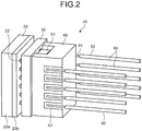
- FIG. 2 is a perspective view of the imaging unit arranged in the distal end portion of the endoscope illustrated in FIG. 1 .
- FIG. 3 is an exploded view of the imaging unit illustrated in FIG. 2 .
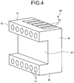
- FIG. 4 is a perspective view of a bottom side of a deformed circuit board used in the imaging unit of FIG. 2 .
- An imaging unit 10 is configured to include a semiconductor package 20 which includes an image sensor and where connection electrodes 21 are formed on an f2 face that is a back side, a first circuit board 30 where connection electrodes are formed on an f3 face that is a front side and an f4 face that is a back side (the connection electrodes of the f3 face are not illustrated in the drawing and the connection electrodes of the f4 face are denoted by reference sign 33) and the connection electrodes of the f3 face are electrically and mechanically connected to the connection electrodes 21 of the semiconductor package 20, a deformed circuit board 40 where connection electrodes 41 and 42 are formed on an f5 face that is a first face and on f6 and f7 faces that are second and third faces, respectively, and the connection electrodes 41 of the f5 face that is the first face are electrically and mechanically connected to the connection electrodes 33 of the circuit board 30, electronic components 51 and 52 which are mounted on the f4 face that is the back side of the circuit board 30, and a plurality of cables
- the electronic components 51 and 52 are housed in a recess 43 on the f5 face of the deformed circuit board 40.
- the circuit board 30, the deformed circuit board 40, and the cables 60 connected to the connection electrodes 42 of the f6 and f7 faces is located within a projection plane in an optical axis direction of the semiconductor package 20.
- the semiconductor package 20 has a structure where glass 20a is adhered to an image sensor 20b. Light collected by a lens unit is incident on an f0 face (light-receiving plane) of the image sensor 20b including a light receiving portion through an f1 face that is the front side of the glass 20a.
- the connection electrodes 21 and bumps 22 made of solder or the like are formed on an f2 face (back side) of the image sensor 20b.
- the semiconductor package 20 is a CSP (Chip Size Package) where wiring, electrode formation, resin sealing, and dicing are formed on an image sensor chip in a wafer state, and finally, a size of the image sensor chip becomes the size of the semiconductor package.
- CSP Chip Size Package
- the circuit board 30 formed in a plate shape where a plurality of substrates where wire lines are formed are layered (a plurality of substrates parallel to the f3 face and the f4 face is layered).
- the multi-layer substrate used is a ceramic substrate, a glass epoxy substrate, a flexible substrate, a glass substrate, a silicon substrate, or the like.
- a plurality of vias 32 which conductively connects the wire lines on the multi-layer substrate is formed inside the circuit board 30 (refer to FIG. 7 ).
- Mounting lands 35 where the electronic components 51 and 52 are mounted are provided on the f4 face of the circuit board 30.
- the connection electrodes 33 of the f4 face and the mounting lands 35 are connected to the connection electrodes of the f3 face by the vias 32.
- the electronic components 51 and 52 there may be exemplified passive parts such as capacitors, resistors, and coils and active parts such as driver ICs, waveform shaping circuit ICs, crystal oscillators, VCSELs, and PDs.
- passive parts such as capacitors, resistors, and coils
- active parts such as driver ICs, waveform shaping circuit ICs, crystal oscillators, VCSELs, and PDs.
- driver ICs such as capacitors, resistors, and coils
- active parts such as driver ICs, waveform shaping circuit ICs, crystal oscillators, VCSELs, and PDs.
- FIG. 3 three electronic components 51 and one electronic component 52 are mounted.
- the types and numbers of mounted electronic components 51 and 52 are not limited thereto.
- Connection electrodes are formed on the f3 face of the circuit board 30 and are electrically and mechanically connected to the connection electrodes 21 of the semiconductor package 20 through bumps 22. Connecting portions between the connection electrodes of the f3 face and the connection electrodes 21 of the f2 face are sealed by a sealing resin 23 (refer to FIG. 7 ).
- the deformed circuit board 40 is made of a ceramic substrate, a glass epoxy substrate, a silicon substrate, or the like and forms an irregular shape by layering a plurality of substrates where wire lines are formed (a plurality of substrates parallel to the f5 face and the f8 face). As illustrated in FIG. 4 , the recess 43 is formed on the f5 face of the deformed circuit board 40, and the recess 43 penetrates from an f9 face to an f10 face. The recess 43 has a size of accommodating the electronic components 51 and 52 mounted on the f4 face of the circuit board 30.
- the f2 face that is the back side of the semiconductor package 20 and the f3 face of the circuit board 30 are connected to each other, and the electronic components 51 and 52 are mounted in the vicinity of the center of the circuit board 30, so that the distance between the image sensor and the electronic components can be shortened. Therefore, impedance can be reduced, and the stable driving of the image sensor can be performed, so that high-quality image can be obtained.
- the recess 43 is provided on the f5 face of the deformed circuit board 40 to accommodate the electronic components 51 and 52, so that the length of a hard portion (optical-axis-direction length of a hard portion of the imaging unit 10) can be shorted.
- the recess 43 of the deformed circuit board 40 is not limited to the recess illustrated in FIG. 4 .
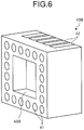
- Examples of the recess include a recess 43A in which an opening is provided only on one face (f9 face) as illustrated in FIG. 5 , or a recess 43B in which no opening is provided except for the f5 face as illustrated in FIG. 6 .
- the recess 43 is opened in the f9 face and the f10 face.
- the recess may be opened in the f6 and f7 faces where the connection electrodes 42 are formed.
- the shape of the recess 43 may be appropriately selected according to shapes, mount positions, and the like of the electronic components 51 and 52.
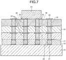
- the vias 32 connecting at least a part of the connection electrodes 21 of the semiconductor package 20 and a connection electrodes 31 of the f3 face and the mounting lands 35 of the circuit board 30 are arranged within an optical-axis-direction projection plane of the mounting lands 35 of the electronic components 51 or 52.
- FIG. 7 is a partial cross-sectional view of the imaging unit illustrated in FIG. 3 . As illustrated in FIG. 7 , the connection electrodes 21 of the semiconductor package 20 are arranged within an optical-axis-direction projection area 38 of the mounting lands 35 of the electronic components 51. In addition, the vias 32 connecting the connection electrodes 31 of the f3 face and the mounting lands 35 of the circuit board 30 are arranged.
- the via 32 arranged in the projection area 38 may have a structure illustrated in FIG. 8 .
- a plurality of vias 32A are arranged in an optical-axis-direction projection area 38A of the mounting lands 35 of the electronic components 51.
- connection electrodes 21 of the semiconductor package 20 are arranged within the optical-axis-direction projection area 38A of the mounting lands 35 of the electronic components 51.
- the impedance can be decreased, and the noise can be reduced.
- connection electrodes 41 are formed in the remaining portion except for the recess 43 of the f5 face of the deformed circuit board 40 and are connected to the connection electrodes 33 of the circuit board 30 by bonding using solder, Au-Au bonding using ultrasound, or the like.
- the connecting portions between the circuit board 30 and the deformed circuit board 40 and the recess 43 accommodating the electronic components 51 and 52 are sealed by a sealing resin (not illustrated).
- connection electrodes 42 connecting the cables 60 are provided on the f6 and f7 faces that are second and third faces of the deformed circuit board 40.
- An insulating outer coat 62 of one end portion of the cable 60 is peeled off, and an exposed conductor 61 is electrically and mechanically connected to the connection electrode 42 by solder (not illustrated).
- the f6 face that is the second face and the f7 face that is the third face are opposite to each other, and the connection electrodes 42 are provided to the opposite faces, so that the connection to the cables 60 is facilitated.
- the connection electrodes 42 may be formed on the f9 and f10 faces.
- the board where the electronic components 51 and 52 and the cables 60 are mounted is divided into the circuit board 30 and the deformed circuit board 40, and the electronic components 51 and 52 are mounted in the vicinity of the center of the circuit board 30 close to the image sensor. Therefore, the impedance between the image sensor and the electronic components 51 and 52 can be decreased.
- terminals of the image sensor there is a degree of freedom in that the terminals of the electronic components 51 and 52 are allowed to be close even to terminals in the vicinity of the center of the image sensor or to terminals in the outer periphery of the image sensor according to the situation.
- the electronic components 51 and 52 are mounted on the back side of the circuit board and are accommodated in the recess 43 formed on the front side (f5 face) of the deformed circuit board 40, it is possible to change the arrangement configuration of the electronic components 51 and 52 more simply and inexpensively.
- circuit board 30, the deformed circuit board 40, and cables 60 are located within the projection plane in the optical axis direction of the semiconductor package 20, it is possible to achieve a small diameter of the imaging unit 10.
- the connection to the semiconductor package 20 or the connection between the circuit board 30 and the deformed circuit board 40 is performed on the f3, f4, and f5 faces where fine-pitch wire lines can be formed and which are parallel to the substrate surface, it is possible to obtain a small-sized, highly-reliable imaging unit 10.
- FIG. 9 is a perspective view of the imaging unit according to the second embodiment of the present invention.
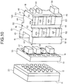
- FIG. 10 is an exploded view of the imaging unit illustrated in FIG. 9 .
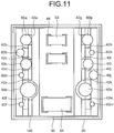
- FIG. 11 is a schematic view of the imaging unit illustrated in FIG. 9 as viewed from the proximal end side.
- f6 and f7 faces that are second and third faces of a deformed circuit board 140 are formed to have step shapes being close in the optical-axis-direction proximal end side of the semiconductor package 20. That is, step portions S1, S2, and S3 are formed on the f6 and f7 faces.
- connection electrodes 42a, 42b, 42c, 42d, 42e, and 42f are formed, the connection electrodes 42a, 42b, 42c, 42d, 42e, and 42f are disposed in a staggered arrangement (zigzag shape).
- connection electrodes 42g, 42h, 42i, 42j, 42k, and 42m are formed, and the connection electrodes 42g, 42h, 42i, 42j, 42k, and 42m are disposed in a staggered arrangement (zigzag shape).
- Cables 60a, 60b, 60c, 60d, 60e, and 60f are connected to the respective connection electrodes 42a, 42b, 42c, 42d, 42e, and 42f, and cables 60g, 60h, 60i, 60j, 60k, and 60m are connected to the respective connection electrodes 42g, 42h, 42i, 42j, 42k, and 42m.
- connection electrodes 42e and 42k have groove shapes where the deformed circuit board 140 is hollowed out. Conductors of the cables 60e and 60k are accommodated in the groove-shaped connection electrodes 42e and 42k.
- the connection electrodes 42e and 42k are formed to have the groove shapes and the conductors of the cables 60e and 60k are accommodated to be connected to the connection electrodes, and thus, even in the case where the cables 60e and 60k have large diameters, the cables can be located within the projection plane in the optical axis direction of the semiconductor package 20, so that it is possible to achieve a small diameter of the imaging unit 100.
- connection electrodes 42e and 42k are formed to have the groove shapes, the solder for cable connection is anchored in the multi-layer substrate constituting the deformed circuit board 140, and thus, the connection strength of the cables is improved, so that cable deviation does not easily occur even in the case of a cable having a large diameter.
- the cables 60a to 60m have different outer diameters.
- the cables 60e and 60k having the largest outer diameter are connected to the connection electrodes 42e and 42k provided in the step portion S3 that is the optical-axis-direction proximal end side.
- the f6 and f7 faces that are second and third faces are close in the optical-axis-direction proximal end side of the semiconductor package 20. That is, the width R2 of the step portion S2 on the proximal end side of the step portion S1 is smaller than the width R1 of the step portion S1, and the width R3 of the step portion S3 on the proximal end side of the step portion S2 is smaller than the width R2 of the step portion S2.
- the cables 60e and 60k having the largest outer diameters are connected to the connection electrodes of the step portions S3 having the smallest diameters, and thus, the cables can be located within the projection plane in the optical axis direction of the semiconductor package 20, so that it is possible to achieve a small diameter of the imaging unit 100.
- the side surface of the step portions S1 and S2 have a function as positioning portions of the cables 60a to 60m which are to be connected to the step portions S2 and S3.
- groove portions 44 are provided between the step portions S2 and S3, in other words, between the connection electrodes 42a, 42c, and 42e and the connection electrodes 42b, 42d, and 42f, and between the connection electrodes 42g, 42i, and 42k and the connection electrodes 42h, 42j, and 42m.
- groove portions 45 are provided in the optical-axis-direction proximal end sides of the connection electrodes 42a, 42c, and 42e and the connection electrodes 42g, 42i, and 42k. The groove portions 44 and 45 are provided, and thus, when the cables are connected to the connection electrodes, solder flow can be prevented, so that it is possible to reduce the risk of short circuit or the like.
- the groove portion 44 is coated with alumina, so that the solder flow can be further prevented.
- mounting lands 47 are provided on the f8 face of the deformed circuit board 140, and electronic components 53 and 54 are mounted.
- the electronic components may be mounted on the f8 face.
- decoupling condensers or the like of which impedance is desired to be suppressed by being close to the image sensor may be mounted on the circuit board 30, and coupling condensers or the like of which impedance needs not to be suppressed by being close to the image sensor may be mounted on the f8 face.
- the second and third faces of the deformed circuit board 140 are formed to have stepped shapes being close in the optical-axis-direction proximal end side of the semiconductor package 20, even in the case where cables 60e and 60k or the like having large diameters are used, if the cables 60e and 60k are connected to the step portion S3 of the proximal end side, the cables 60e and 60k can be located within the projection plane in the optical axis direction of the semiconductor package 20, so that it is possible to achieve a small diameter of the imaging unit 100.
- connection electrodes 42b, 42d, and 42f, and connection electrodes 42h, 42j, and 42m arranged in the step portion S2 are formed in the proximal end side from the bottom face of the recess 43, the connection electrodes 42b, 42d, 42f, 42h, 42j, and 42m may be formed at the positions overlapping with the recess 43 in the optical axis direction.
- FIG. 12 is a side view of an imaging unit according to Modified Example of the second embodiment of the present invention. In FIG. 12 , only the cables 60a and 60g are illustrated.
- connection electrodes 42b, 42d, 42f, 42h, 42j, and 42m arranged on the step portion S2 is formed at the position overlapping with the recess 43 in the optical axis direction. Therefore, in Modified Example, the arrangement positions of the connection electrodes 42b, 42d, 42f, 42h, 42j, and 42m can be shifted by h2 toward the f5 face direction in comparison with the second embodiment illustrated in FIG. 12(a) , so that the length of a hard portion of the imaging unit 100A can be shortened by h2.
- FIG. 13 is a perspective view of the imaging unit according to the third embodiment of the present invention.
- FIG. 14 is an exploded view of the imaging unit illustrated in FIG. 13 .
- a recess 36 is provided in an f4 face that is the back side of a circuit board 130.
- Electronic components 51 are mounted on mounting lands 35 in the recess 36.
- connection electrodes 21 and bumps 22 made of solder or the like are arranged on an f2 face that is the back side are connected to connection electrodes (not illustrated) formed on an f3 face that is the front side of the circuit board 130.
- Connection electrodes 33 are provided on an f4 face excluding the recess 36 of the circuit board 130 and are connected to connection electrodes (not illustrated) formed on an f5 face of a deformed circuit board 141.
- step portions S1, S2, S3, and S4 are provided on f9 and f10 faces.
- the f9 face is a second face
- the f10 face is a third face.
- the step portions S1 to S4 are provided so that the f9 and f10 faces are close to each other in the optical-axis-direction proximal end side of the semiconductor package 120.
- Connection electrodes 142a and 142b are arranged in the step portion S2 of the f9 face, connection electrodes 142c and 142d are arranged in the step portion S3, and connection electrodes 142e and 142f are arranged in the step portion S4.
- Connection electrodes 142g and 142h are arranged in the step portion S2 of the f10 face, connection electrodes 142i and 142j (not illustrated) are arranged in the step portion S3, and connection electrodes 142k and 142m (not illustrated) are arranged in the step portion S4.
- cables 63a, 63b, 63c, 63d, 63e, and 64f are connected to the connection electrodes 142a, 142b, 142c, 142d, 142e, and 142f, respectively.
- Cables 63g, 63h, 63i, 63j, 63k, and 63m are connected to the connection electrodes 142g, 142h, 142i, 142j, 142k, and 142m, respectively.
- Groove portions 44 are provided between the step portions S2 and S3 and between the step portions S3 and S4, in other words, between the connection electrodes 142a and 142b and the connection electrodes 142c and 142d, between the connection electrodes 142c and 142d and the connection electrodes 142e and 142f, between the connection electrodes 142g and 142h and the connection electrodes 142i and 142j, and between the connection electrodes 142i and 142j and the connection electrodes 142k and 142m.
- groove portions 45 are provided in the optical-axis-direction proximal end sides of the connection electrodes 142e and 142f and in the optical-axis-direction proximal end side of the connection electrodes 142k and 142m.
- the groove portions 44 and 45 are provided, and thus, when the cables are connected to the connection electrodes, solder flow can be prevented, so that it is possible to reduce the risk of short circuit or the like.
- the recess 36 is formed on the back side (f4 face) of the circuit board 130, and the electronic components 51 and the like are mounted in the recess 36.
- the electronic components 51 and the like are mounted in the vicinity of the center of the circuit board 130 close to the image sensor, it is possible to decrease the impedance between the image sensor and the electronic components 51 and the like.
- the electronic components 51 and the like are mounted in the recess 36 of the circuit board 130, it is possible to change the arrangement configuration of the electronic components 51 and the like more simply and inexpensively. Furthermore, if a recess is formed in the deformed circuit board 141, the board becomes expensive.
- the third embodiment since there is no need to form a recess in the deformed circuit board 141, it is possible to provide an inexpensive imaging unit. Furthermore, in the case where the recess 36 is formed in the circuit board 130, the stress exerted on the semiconductor package 20 can be reduced, so that it is possible to provide a highly-reliable imaging unit.
- each of second and third faces of a deformed circuit board has a gradient which is close in an optical-axis-direction proximal end side of a semiconductor package.
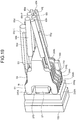
- FIG. 15 is a perspective view of the imaging unit according to the fourth embodiment of the present invention.
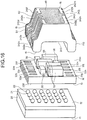
- FIG. 16 is an exploded view of the imaging unit illustrated in FIG. 15 .
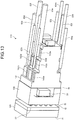
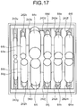
- FIG. 17 is a schematic view of the imaging unit illustrated in FIG. 15 as viewed from the proximal end side.
- f9 and f10 faces that are second and third faces of a deformed circuit board 240 have gradients which are close in the optical-axis-direction proximal end side of the semiconductor package 20.
- the deformed circuit board 240 is an MID (Molded Interconnect Device) board where steric wiring is formed by injection molding.
- MID board is used as the deformed circuit board 240, it is possible to manufacture the imaging unit more simply and inexpensively.
- a base material of the MID board there may be exemplified a liquid crystal polymer, a polyamide, a polycarbonate, or the like.
- connection electrodes 33a, 33b, 33c, 33e, 33f, 33g, 33h, 33i, 33j, 33k, and 33m are provided, and mounting lands where electronic components 55 and 56 are mounted are provided.
- connection electrodes 241a, 241b, 241c, 241e, 241f, 241g, 241h, 241i, 241j, 241k, and 241m are formed to be connected to the respective connection electrodes 33a, 33b, 33c, 33e, 33f, 33g, 33h, 33i, 33j, 33k, and 33m of the circuit board 230.
- the f9 and f10 faces of the deformed circuit board 240 have gradients which are close in the optical-axis-direction proximal end side of the semiconductor package 20, preferably, gradients which form an isosceles triangle when the f9 and f10 faces extend.
- level difference portions S1 and S2 are provided to the f9 and f10 faces, and connection electrodes 242a, 242b, 242c, 242d, 242e, 242f, 242g, 242h, 242i, 242j, 242k, and 242m are arranged on the entire f9 and f10 faces.
- a ground pattern 46 which is connected to the connection electrodes 242c, 242d, and 242j is formed on the f8 face.
- connection electrodes 242a, 242b, 242e, 242f, 242g, 242h, 242i, 242j, 242k, and 242m extend from the connection electrodes 241a, 241b, 241e, 241f, 241g, 241h, 241i, 241j, 241k, and 241m of the f5 face to the f9 or f10 face, and the connection electrodes 242c and 242d are branched from the connection electrode 241c in the level difference portion S2 of the f9 face.
- Cables 64a, 64b, 64c, 64d, 64e, 64f, 64g, 64h, 64i, 64j, 64k, and 64m are connected to the respective connection electrodes 242a, 242b, 242c, 242d, 242e, 242f, 242g, 242h, 242i, 242j, 242k, and 242m in the level difference portion S2.
- the cables 64a to 64m are cables constituting a composite cable which bundles a plurality of cables and is covered with an outer coat shield and an outer coat.
- the outer coat shield and the outer coat of one end portion of the composite cable are peeled off, and after that, the individual cables 64a to 64m are decomposed to be connected.
- the f9 and f10 faces have the gradients which are close in the optical-axis-direction proximal end side, in comparison with the case where the faces are horizontal, it is possible to easily perform the connection to the connection electrodes 242a to 242m of the cables 64a to 64m (to easily performing setting to a tool for connection to the cables 64a to 64m).
- the cables 64a to 64m are arranged so as to extend along the f9 and f10 faces, the exposed portions from the outer coat shield of the cables 64a to 64m are shortened, so that external influence can be reduced.
- connection electrodes 241a, 241b, 241c, 241e, 241f, 241g, 241h, 241i, 241j, 241k, and 241m of the f5 face are formed up to the end portion of the f5 face to become the connection electrodes 242a, 242b, 242c, 242d, 242e, 242f, 242g, 242h, 242i, 242j, 242k, and 242m of the f9 or f10 face, when the connection electrodes are to be connected to the respective connection electrodes 33a, 33b, 33c, 33e, 33f, 33g, 33h, 33i, 33j, 33k, and 33m, solder fillets are formed, so that it is possible to improve connection strength between the circuit board 230 and the deformed circuit board 240.
- FIG. 18 is a perspective view of an imaging unit according to Modified Example of the fourth embodiment of the present invention.
- FIG. 19 is a perspective view of the imaging unit illustrated in FIG. 18 as viewed from the lower side.
- FIG. 20 is an exploded view of the imaging unit illustrated in FIG. 18 .
- FIG. 21 is a schematic view of the imaging unit illustrated in FIG. 18 as viewed from the proximal end side.
- an electronic component 160 is mounted on an f10 that is a third face.
- connection electrodes 233a, 233b, 233c, 233d, 233g, 233h, 233i, 233j, and 233k are arranged, mounting lands where electronic components 57 and 58 are mounted are provided.
- connection electrodes 245a, 245b, 245c, 245d, 245g, 245h, 245i, 245j, and 241k are formed to be connected to the respective connection electrodes 233a, 233b, 233c, 233d, 233g, 233h, 233i, 233j, and 233k of the circuit board 230A.
- connection electrodes 244a, 244b, 244c, 244d, 244g, 244h, 244i, 244j, and 244k are arranged on the entire f9 and f10 faces.
- a connection electrode 244e is formed in a level difference portion S3 of the f9 face.
- connection electrodes 244a, 244b, 244c, 244d, 244g, 244h, 244i, 244j, and 244k extend from the respective connection electrodes 245a, 245b, 245c, 245d, 245g, 245h, 245i, 245j, and 245k of the f5 face to the f9 or f10 face.
- Cables 65a, 65b, 65d, 65e, 65g, 65h, 65i, 65j, and 65k are connected to the connection electrodes 244a, 244b, 244d, 244e, 24dg, 244h, 244i, 244j, and 244k, respectively on the level difference portion S2 or S3. Cables 65c-1 and 65c-2 are connected to the level difference portions S2 and S3 of the connection electrode 244c, respectively.
- An imaging unit and an imaging module of the present invention are useful for an endoscope system requiring high-quality image and a small diameter of distal end portion.
Landscapes
- Health & Medical Sciences (AREA)
- Life Sciences & Earth Sciences (AREA)
- Surgery (AREA)
- Physics & Mathematics (AREA)
- Optics & Photonics (AREA)
- Engineering & Computer Science (AREA)
- Biomedical Technology (AREA)
- Veterinary Medicine (AREA)
- Biophysics (AREA)
- Pathology (AREA)
- Radiology & Medical Imaging (AREA)
- Nuclear Medicine, Radiotherapy & Molecular Imaging (AREA)
- Public Health (AREA)
- Heart & Thoracic Surgery (AREA)
- Medical Informatics (AREA)
- Molecular Biology (AREA)
- Animal Behavior & Ethology (AREA)
- General Health & Medical Sciences (AREA)
- Multimedia (AREA)
- Astronomy & Astrophysics (AREA)
- General Physics & Mathematics (AREA)
- Signal Processing (AREA)
- Endoscopes (AREA)
- Studio Devices (AREA)
- Instruments For Viewing The Inside Of Hollow Bodies (AREA)
Abstract
Description
- The present invention relates to an imaging unit provided at a distal end of an insertion unit of an endoscope configured to be inserted into a subject to image an inside of the subject. The present invention also relates to an imaging module and an endoscope system. Background
- In the related art, endoscope devices are widely used for various examinations in medical fields and industrial fields. Among them, in medical endoscope devices, a flexible insertion unit having an elongated shape where an image sensor is provided at a distal end thereof is inserted into a body cavity of a subject such as a patient, and thus, an in-vivo image in the body cavity can be acquired without making an incision. In addition, a treatment tool is allowed to protrude from the distal end of the insertion unit to perform therapeutic treatment if necessary. Therefore, the medical endoscope devices have been widely used.
- An imaging unit including an image sensor and a circuit board where electronic components such as condensers or IC chips constituting a driving circuit for the image sensor are mounted is fitted into the distal end of the insertion unit of the endoscope device, and the circuit board of the imaging unit is connected to a cable by solder.
- In recent years, for the purpose of simplifying an operation of connecting a signal line of the cable, improving reliability of connected portions, or miniaturizing, imaging units where a circuit board connected to an image sensor is formed in a steric structure have been proposed (for example, refer to
Patent Literatures 1 to 5). -
- Patent Literature 1:
JP 2005-278760 A - Patent Literature 2:
JP 2006-223624 A - Patent Literature 3:
JP 2000-199863 A - Patent Literature 4:
JP 2013-197501 A - Patent Literature 5:
JP 2014-110847 A - However, in
Patent Literatures 1 to 5, since electronic components are mounted at positions far away from an image sensor, particularly, at positions far away from the vicinity of the center of the image sensor, impedance is increased, so that noise is generated. For this reason, the image sensor may be stably driven, so that image quality may be deteriorated. Particularly, this problem is remarkable when the image sensor is implemented as a high-speed element. - The present invention has been made in view of the foregoing, and an object of the invention is to provide an imaging unit, an imaging module, and an endoscope system which are able to achieve a small diameter and to obtain a high-quality image.
- In order to solve the above described problem and achieve the object, an imaging unit according to the invention includes: a semiconductor package having an image sensor and having a connection electrode on a back side thereof; a circuit board having connection electrodes on front and back sides thereof, the connection electrode on the front side being electrically and mechanically connected to the connection electrode of the semiconductor package; a deformed circuit board having at least first, second, and third faces and having connection electrodes on the first, second, and third faces, respectively, a connection electrode of the connection electrodes on the first face being electrically and mechanically connected to the connection electrodes of the circuit board; an electronic component mounted on the back side of the circuit board; and a plurality of cables electrically and mechanically connected to the connection electrodes on the second and third faces of the deformed circuit board. The circuit board or the deformed circuit board has a recess on the back side or on the first face, respectively, the electronic component is housed in the recess. The circuit board, the deformed circuit board, and the plurality of cables connected to the connection electrodes on the second and third faces are located within a projection plane in an optical axis direction of the semiconductor package.
- In the imaging unit according to the above-described invention, at least one of the connection electrodes on the second and third faces has a groove shape so as to house a conductor of one of the cables.
- In the imaging unit according to above-described invention, the second and third faces of the deformed circuit board face opposite directions, the second and third faces have step portions which are close to each other on a proximal end side in the optical axis direction of the image sensor, and the connection electrodes are formed on the step portions, respectively.
- In the imaging unit according to above-described invention, the connection electrodes are disposed in a staggered arrangement, and among the plurality of cables, a cable having a large outer diameter is connected to one of the connection electrodes that is provided on the proximal end side in the optical axis direction.
- In the imaging unit according to above-described invention, groove portions are formed on the second and third faces in forward and backward directions of the optical axis direction between the connection electrodes.
- In the imaging unit according to above-described invention, the second and third faces of the deformed circuit board face opposite directions, and the second and third faces have gradients such that the second and third faces are close to each other on a proximal end side in the optical axis direction of the image sensor.
- In the imaging unit according to above-described invention, level difference portions are provided on the second and third faces, and the connection electrodes are arranged in the level difference portions.
- In the imaging unit according to above-described invention, the electronic component is housed in the recess on the first face of the deformed circuit board, and a part of the connection electrodes on the second and third faces is formed at a position overlapping with the recess in the optical axis direction.
- In the imaging unit according to above-described invention, the electronic component is mounted in the recess on the back side of the circuit board, and the connection electrodes are formed on a surface except for the recess on the back side of the circuit board.
- In the imaging unit according to above-described invention, within a projection area in the optical axis direction of a mounting land on which the electronic component is mounted, a via for connecting at least a part of the connection electrode of the semiconductor package and the connection electrode on the front side of the circuit board to the mounting land on the back side of the circuit board is arranged.
- An imaging module according to the invention includes: a semiconductor package having an image sensor and having a connection electrode on a back side thereof; a circuit board having connection electrodes on front and back sides thereof, the connection electrode on the front side being electrically and mechanically connected to the connection electrode of the semiconductor package; a deformed circuit board having at least first, second, and third faces and having connection electrodes on the first, second, and third faces, respectively, a connection electrode of the connection electrodes on the first face being electrically and mechanically connected to the connection electrodes of the circuit board, a plurality of cables being electrically and mechanically connected to the connection electrodes on the second and third faces; and an electronic component mounted on the back side of the circuit board. The circuit board or the deformed circuit board has a recess on the back side or on the first face, respectively. The electronic component is housed in the recess, and the circuit board and the deformed circuit board are located within a projection plane in an optical axis direction of the semiconductor package.
- An endoscope system according to the invention includes an insertion unit in which the imaging unit according to above-described invention is provided at a distal end of the insertion unit.
- According to the present invention, because an electronic component is arranged in the immediate vicinity of an image sensor through a circuit board which is close to the image sensor, it is possible to drive the image sensor at a high speed, and to achieve a small diameter of and to obtain a high-quality image.
-
-
FIG. 1 is a schematic view illustrating an overall configuration of an endoscope system according to a first embodiment of the present invention. -
FIG. 2 is a perspective view of an imaging unit arranged in a distal end portion of an endoscope illustrated inFIG. 1 . -
FIG. 3 is an exploded view of the imaging unit illustrated inFIG. 2 . -
FIG. 4 is a perspective view of a bottom side of a deformed circuit board used in the imaging unit ofFIG. 2 . -
FIG. 5 is a perspective view of Modified Example 1 of the deformed circuit board. -
FIG. 6 is a perspective view of Modified Example 2 of the deformed circuit board. -
FIG. 7 is a partial cross-sectional view of the imaging unit illustrated inFIG. 3 . -
FIG. 8 is a cross-sectional view illustrating arrangement of electronic components and connection electrodes. -
FIG. 9 is a perspective view of an imaging unit according to a second embodiment of the present invention. -
FIG. 10 is an exploded view of the imaging unit illustrated inFIG. 9 . -
FIG. 11 is a schematic view of the imaging unit illustrated inFIG. 9 as viewed from the proximal end side. -
FIG. 12 is a side view of an imaging unit according to Modified Example of the second embodiment of the present invention. -
FIG. 13 is a perspective view of an imaging unit according to a third embodiment of the present invention. -
FIG. 14 is an exploded view of the imaging unit illustrated inFIG. 13 . -
FIG. 15 is a perspective view of an imaging unit according to a fourth embodiment of the present invention. -
FIG. 16 is an exploded view of the imaging unit illustrated inFIG. 15 . -
FIG. 17 is a schematic view of the imaging unit illustrated inFIG. 15 as viewed from the proximal end side. -
FIG. 18 is a perspective view of an imaging unit according to Modified Example of the fourth embodiment of the present invention. -
FIG. 19 is a perspective view of the imaging unit illustrated inFIG. 18 as viewed from the lower side. -
FIG. 20 is an exploded view of the imaging unit illustrated inFIG. 18 . -
FIG. 21 is a schematic view of the imaging unit illustrated inFIG. 18 as viewed from the proximal end side. Description of Embodiments - Reference will be made below to endoscope systems including an imaging unit as modes for carrying out the present invention (hereinafter, referred to as "embodiment(s)"). The present invention is not limited to the embodiments. The same reference signs are used to designate the same elements throughout the drawings. The drawings are schematic ones, and thus, a relationship among thickness and widths of components, a ratio among the components, and the like are different from real ones. In addition, figures may include portions of which dimensions and ratios are different.
-
FIG. 1 is a schematic view illustrating an overall configuration of an endoscope system according to a first embodiment of the present invention. As illustrated inFIG. 1 , anendoscope system 1 according to the first embodiment is configured to include anendoscope 2 configured to be inserted into a subject and to image an inside of the subject to generate an in-vivo image signal of the subject, aninformation processing device 3 which performs a predetermined image process on the image signal obtained by the capturing of theendoscope 2 and controls components of theendoscope system 1, alight source device 4 which generates illumination light of theendoscope 2, and adisplay device 5 which displays an image of the image signal which is image-processed by theinformation processing device 3. - The
endoscope 2 is configured to include aninsertion unit 6 configured to be inserted into the subject, anoperating unit 7 which is a proximal end side of theinsertion unit 6 and is gripped by an operator, and a flexibleuniversal cord 8 which extends from theoperating unit 7. - The
insertion unit 6 is implemented by using an illumination fiber (light guide cable), an electric cable, and an optical fiber, or the like. Theinsertion unit 6 includes adistal end portion 6a incorporating an imaging unit described later, abendable bending portion 6b configured with a plurality of bending pieces, and aflexible tube portion 6c having flexibility and being provided to a proximal end side of the bendingportion 6b. Thedistal end portion 6a is provided with an illumination unit which illuminates the inside of the subject through an illumination lens, an observation unit configured to image the inside of the subject, an opening which communicates with a treatment tool channel, and air/water supply nozzle (not illustrated). - The
operating unit 7 includes a bendingknob 7a bending the bendingportion 6b in the up/down direction and the left/right direction, a treatmenttool insertion unit 7b inserting a treatment tool such as biological forceps and laser scalpel into a body cavity of the subject, and a plurality ofswitches 7c performing operations of peripheral devices such as theinformation processing device 3, thelight source device 4, an air supply device, a water supply device, and a gas supply device. The treatment tool inserted from the treatmenttool insertion unit 7b is exposed to the opening in the distal end of theinsertion unit 6 through the treatment tool channel provided inside theoperating unit 7. - The
universal cord 8 is configured by using an illumination fiber, a cable, or the like. Theuniversal cord 8 is branched at the proximal end. The branched one end is aconnector 8a, and the other proximal end is aconnector 8b. Theconnector 8a is detachable to a connector of theinformation processing device 3. Theconnector 8b is detachable to thelight source device 4. Theuniversal cord 8 allows the illumination light emitted from thelight source device 4 to propagate through theconnector 8b and an illumination fiber to thedistal end portion 6a. In addition, theuniversal cord 8 transmits the image signal obtained by the capturing of the imaging unit described later through a cable and theconnector 8a to theinformation processing device 3. - The
information processing device 3 performs a predetermined image process on the image signal output from theconnector 8a and controls theoverall endoscope system 1. - The
light source device 4 is configured by using a light source emitting light, a condenser lens, and the like. Under the control of theinformation processing device 3, thelight source device 4 allows the light source to emit light and supplies the light as illumination light for the subject as an object to theendoscope 2 connected through theconnector 8b and the illumination fiber of theuniversal cord 8. - The
display device 5 is configured by using a display or the like using a liquid crystal display or an organic EL (Electro Luminescence) device. Thedisplay device 5 displays various types of information including images obtained from a predetermined image process performed by theinformation processing device 3 through animage cable 5a. The operator operates theendoscope 2 while viewing the image (in-vivo image) displayed on thedisplay device 5, so that the operator can observe a desired position in the subject and determine properties and state of the position. - Next, the imaging unit used in the
endoscope system 1 will be described in detail.FIG. 2 is a perspective view of the imaging unit arranged in the distal end portion of the endoscope illustrated inFIG. 1 .FIG. 3 is an exploded view of the imaging unit illustrated inFIG. 2 .FIG. 4 is a perspective view of a bottom side of a deformed circuit board used in the imaging unit ofFIG. 2 . - An
imaging unit 10 is configured to include asemiconductor package 20 which includes an image sensor and whereconnection electrodes 21 are formed on an f2 face that is a back side, afirst circuit board 30 where connection electrodes are formed on an f3 face that is a front side and an f4 face that is a back side (the connection electrodes of the f3 face are not illustrated in the drawing and the connection electrodes of the f4 face are denoted by reference sign 33) and the connection electrodes of the f3 face are electrically and mechanically connected to theconnection electrodes 21 of thesemiconductor package 20, adeformed circuit board 40 whereconnection electrodes connection electrodes 41 of the f5 face that is the first face are electrically and mechanically connected to theconnection electrodes 33 of thecircuit board 30,electronic components circuit board 30, and a plurality ofcables 60 which are electrically and mechanically connected to theconnection electrodes 42 of the f6 and f7 faces that are second and third faces of thedeformed circuit board 40. - In the first embodiment, the
electronic components recess 43 on the f5 face of thedeformed circuit board 40. Thecircuit board 30, thedeformed circuit board 40, and thecables 60 connected to theconnection electrodes 42 of the f6 and f7 faces is located within a projection plane in an optical axis direction of thesemiconductor package 20. - The
semiconductor package 20 has a structure whereglass 20a is adhered to animage sensor 20b. Light collected by a lens unit is incident on an f0 face (light-receiving plane) of theimage sensor 20b including a light receiving portion through an f1 face that is the front side of theglass 20a. Theconnection electrodes 21 and bumps 22 made of solder or the like are formed on an f2 face (back side) of theimage sensor 20b. Preferably, thesemiconductor package 20 is a CSP (Chip Size Package) where wiring, electrode formation, resin sealing, and dicing are formed on an image sensor chip in a wafer state, and finally, a size of the image sensor chip becomes the size of the semiconductor package. - The
circuit board 30 formed in a plate shape where a plurality of substrates where wire lines are formed are layered (a plurality of substrates parallel to the f3 face and the f4 face is layered). As the multi-layer substrate, used is a ceramic substrate, a glass epoxy substrate, a flexible substrate, a glass substrate, a silicon substrate, or the like. A plurality ofvias 32 which conductively connects the wire lines on the multi-layer substrate is formed inside the circuit board 30 (refer toFIG. 7 ). Mounting lands 35 where theelectronic components circuit board 30. Theconnection electrodes 33 of the f4 face and the mounting lands 35 are connected to the connection electrodes of the f3 face by thevias 32. As theelectronic components FIG. 3 , threeelectronic components 51 and oneelectronic component 52 are mounted. However, the types and numbers of mountedelectronic components - Connection electrodes (not illustrated) are formed on the f3 face of the
circuit board 30 and are electrically and mechanically connected to theconnection electrodes 21 of thesemiconductor package 20 throughbumps 22. Connecting portions between the connection electrodes of the f3 face and theconnection electrodes 21 of the f2 face are sealed by a sealing resin 23 (refer toFIG. 7 ). - The
deformed circuit board 40 is made of a ceramic substrate, a glass epoxy substrate, a silicon substrate, or the like and forms an irregular shape by layering a plurality of substrates where wire lines are formed (a plurality of substrates parallel to the f5 face and the f8 face). As illustrated inFIG. 4 , therecess 43 is formed on the f5 face of thedeformed circuit board 40, and therecess 43 penetrates from an f9 face to an f10 face. Therecess 43 has a size of accommodating theelectronic components circuit board 30. In the first embodiment, the f2 face that is the back side of thesemiconductor package 20 and the f3 face of thecircuit board 30 are connected to each other, and theelectronic components circuit board 30, so that the distance between the image sensor and the electronic components can be shortened. Therefore, impedance can be reduced, and the stable driving of the image sensor can be performed, so that high-quality image can be obtained. In addition, therecess 43 is provided on the f5 face of thedeformed circuit board 40 to accommodate theelectronic components recess 43 of thedeformed circuit board 40 is not limited to the recess illustrated inFIG. 4 . Examples of the recess include arecess 43A in which an opening is provided only on one face (f9 face) as illustrated inFIG. 5 , or arecess 43B in which no opening is provided except for the f5 face as illustrated inFIG. 6 . In the first embodiment, therecess 43 is opened in the f9 face and the f10 face. However, the recess may be opened in the f6 and f7 faces where theconnection electrodes 42 are formed. The shape of therecess 43 may be appropriately selected according to shapes, mount positions, and the like of theelectronic components - In the
imaging unit 10, thevias 32 connecting at least a part of theconnection electrodes 21 of thesemiconductor package 20 and aconnection electrodes 31 of the f3 face and the mounting lands 35 of thecircuit board 30 are arranged within an optical-axis-direction projection plane of the mounting lands 35 of theelectronic components FIG. 7 is a partial cross-sectional view of the imaging unit illustrated inFIG. 3 . As illustrated inFIG. 7 , theconnection electrodes 21 of thesemiconductor package 20 are arranged within an optical-axis-direction projection area 38 of the mounting lands 35 of theelectronic components 51. In addition, thevias 32 connecting theconnection electrodes 31 of the f3 face and the mounting lands 35 of thecircuit board 30 are arranged. In the first embodiment, since theelectronic components 51 are connected to the image sensor in thesemiconductor package 20 in a straightly-lined manner through the straight-line-shapedvias 32 and theconnection electrodes 21, the impedance between the image sensor and theelectronic components 51 can be decreased, so that noise can be reduced. In addition, the via 32 arranged in theprojection area 38 may have a structure illustrated inFIG. 8 . InFIG. 8 , a plurality ofvias 32A are arranged in an optical-axis-direction projection area 38A of the mounting lands 35 of theelectronic components 51. Twovias 32A-1 and twovias 32A-2 are arranged in a first layer just below the mountingland 35 and a second layer as the subsequent layer, respectively, and one via 32A-3 is conductively connected in a final layer to be connected to theconnection electrodes 31. In this case, theconnection electrodes 21 of thesemiconductor package 20 are arranged within the optical-axis-direction projection area 38A of the mounting lands 35 of theelectronic components 51. In the structure ofFIG. 8 , since the plurality ofvias 32A is arranged, in comparison with the case where one via is arranged, the impedance can be decreased, and the noise can be reduced. - The
connection electrodes 41 are formed in the remaining portion except for therecess 43 of the f5 face of thedeformed circuit board 40 and are connected to theconnection electrodes 33 of thecircuit board 30 by bonding using solder, Au-Au bonding using ultrasound, or the like. The connecting portions between thecircuit board 30 and thedeformed circuit board 40 and therecess 43 accommodating theelectronic components - The
connection electrodes 42 connecting thecables 60 are provided on the f6 and f7 faces that are second and third faces of thedeformed circuit board 40. An insulatingouter coat 62 of one end portion of thecable 60 is peeled off, and an exposedconductor 61 is electrically and mechanically connected to theconnection electrode 42 by solder (not illustrated). The f6 face that is the second face and the f7 face that is the third face are opposite to each other, and theconnection electrodes 42 are provided to the opposite faces, so that the connection to thecables 60 is facilitated. In the first embodiment, although theconnection electrodes 42 are formed on the f6 and f7 faces, theconnection electrodes 42 may be formed on the f9 and f10 faces. - In the first embodiment, the board where the
electronic components cables 60 are mounted is divided into thecircuit board 30 and thedeformed circuit board 40, and theelectronic components circuit board 30 close to the image sensor. Therefore, the impedance between the image sensor and theelectronic components electronic components electronic components recess 43 formed on the front side (f5 face) of thedeformed circuit board 40, it is possible to change the arrangement configuration of theelectronic components - In addition, since the
circuit board 30, thedeformed circuit board 40, andcables 60 are located within the projection plane in the optical axis direction of thesemiconductor package 20, it is possible to achieve a small diameter of theimaging unit 10. In addition, in thecircuit board 30 and thedeformed circuit board 40, the connection to thesemiconductor package 20 or the connection between thecircuit board 30 and thedeformed circuit board 40 is performed on the f3, f4, and f5 faces where fine-pitch wire lines can be formed and which are parallel to the substrate surface, it is possible to obtain a small-sized, highly-reliable imaging unit 10. - In an imaging unit according to a second embodiment, second and third faces of a deformed circuit board are formed to have step shapes being close in an optical-axis-direction proximal end side of a semiconductor package.
FIG. 9 is a perspective view of the imaging unit according to the second embodiment of the present invention.FIG. 10 is an exploded view of the imaging unit illustrated inFIG. 9 .FIG. 11 is a schematic view of the imaging unit illustrated inFIG. 9 as viewed from the proximal end side. - In an
imaging unit 100 according to the second embodiment, as illustrated inFIGS. 9 to 11 , f6 and f7 faces that are second and third faces of adeformed circuit board 140 are formed to have step shapes being close in the optical-axis-direction proximal end side of thesemiconductor package 20. That is, step portions S1, S2, and S3 are formed on the f6 and f7 faces. - In the step portions S2 and S3 of the f6 face,
connection electrodes connection electrodes connection electrodes connection electrodes Cables respective connection electrodes cables respective connection electrodes - The
connection electrodes deformed circuit board 140 is hollowed out. Conductors of thecables connection electrodes connection electrodes cables cables semiconductor package 20, so that it is possible to achieve a small diameter of theimaging unit 100. In addition, since theconnection electrodes deformed circuit board 140, and thus, the connection strength of the cables is improved, so that cable deviation does not easily occur even in the case of a cable having a large diameter. - The
cables 60a to 60m have different outer diameters. Among thecables 60a to 60m, thecables connection electrodes semiconductor package 20. That is, the width R2 of the step portion S2 on the proximal end side of the step portion S1 is smaller than the width R1 of the step portion S1, and the width R3 of the step portion S3 on the proximal end side of the step portion S2 is smaller than the width R2 of the step portion S2. Therefore, thecables semiconductor package 20, so that it is possible to achieve a small diameter of theimaging unit 100. In addition, the side surface of the step portions S1 and S2 have a function as positioning portions of thecables 60a to 60m which are to be connected to the step portions S2 and S3. - In addition,
groove portions 44 are provided between the step portions S2 and S3, in other words, between theconnection electrodes connection electrodes connection electrodes connection electrodes groove portions 45 are provided in the optical-axis-direction proximal end sides of theconnection electrodes connection electrodes groove portions groove portion 44 is coated with alumina, so that the solder flow can be further prevented. - In addition, mounting lands 47 are provided on the f8 face of the
deformed circuit board 140, andelectronic components circuit board 30, in the case where there are a large number of to-be-mounted electronic components, the electronic components may be mounted on the f8 face. For example, decoupling condensers or the like of which impedance is desired to be suppressed by being close to the image sensor may be mounted on thecircuit board 30, and coupling condensers or the like of which impedance needs not to be suppressed by being close to the image sensor may be mounted on the f8 face. - In the second embodiment, since the second and third faces of the
deformed circuit board 140 are formed to have stepped shapes being close in the optical-axis-direction proximal end side of thesemiconductor package 20, even in the case wherecables cables cables semiconductor package 20, so that it is possible to achieve a small diameter of theimaging unit 100. - In addition, in the second embodiment, although the
connection electrodes connection electrodes recess 43, theconnection electrodes recess 43 in the optical axis direction.FIG. 12 is a side view of an imaging unit according to Modified Example of the second embodiment of the present invention. InFIG. 12 , only thecables - As illustrated in
FIG. 12(b) , in animaging unit 100A according to Modified Example, a length h1 in the optical axis direction of the step portion S1 is small, and thus, a part ofconnection electrodes recess 43 in the optical axis direction. Therefore, in Modified Example, the arrangement positions of theconnection electrodes FIG. 12(a) , so that the length of a hard portion of theimaging unit 100A can be shortened by h2. - In an imaging unit according to a third embodiment, electronic components are mounted in a recess formed in a circuit board.
FIG. 13 is a perspective view of the imaging unit according to the third embodiment of the present invention.FIG. 14 is an exploded view of the imaging unit illustrated inFIG. 13 . - In an
imaging unit 110 according to the third embodiment, as illustrated inFIGS. 13 andFIG. 14 , arecess 36 is provided in an f4 face that is the back side of acircuit board 130.Electronic components 51 are mounted on mountinglands 35 in therecess 36. - In a
semiconductor package 120,connection electrodes 21 and bumps 22 made of solder or the like are arranged on an f2 face that is the back side are connected to connection electrodes (not illustrated) formed on an f3 face that is the front side of thecircuit board 130.Connection electrodes 33 are provided on an f4 face excluding therecess 36 of thecircuit board 130 and are connected to connection electrodes (not illustrated) formed on an f5 face of adeformed circuit board 141. - In the
deformed circuit board 141, step portions S1, S2, S3, and S4 are provided on f9 and f10 faces. In the third embodiment, the f9 face is a second face, and the f10 face is a third face. The step portions S1 to S4 are provided so that the f9 and f10 faces are close to each other in the optical-axis-direction proximal end side of thesemiconductor package 120. -
Connection electrodes connection electrodes connection electrodes - In addition,
cables connection electrodes Cables -
Groove portions 44 are provided between the step portions S2 and S3 and between the step portions S3 and S4, in other words, between theconnection electrodes connection electrodes connection electrodes connection electrodes groove portions 45 are provided in the optical-axis-direction proximal end sides of theconnection electrodes groove portions - In the third embodiment, the
recess 36 is formed on the back side (f4 face) of thecircuit board 130, and theelectronic components 51 and the like are mounted in therecess 36. In the third embodiment, since theelectronic components 51 and the like are mounted in the vicinity of the center of thecircuit board 130 close to the image sensor, it is possible to decrease the impedance between the image sensor and theelectronic components 51 and the like. In addition, since theelectronic components 51 and the like are mounted in therecess 36 of thecircuit board 130, it is possible to change the arrangement configuration of theelectronic components 51 and the like more simply and inexpensively. Furthermore, if a recess is formed in thedeformed circuit board 141, the board becomes expensive. However, in the third embodiment, since there is no need to form a recess in thedeformed circuit board 141, it is possible to provide an inexpensive imaging unit. Furthermore, in the case where therecess 36 is formed in thecircuit board 130, the stress exerted on thesemiconductor package 20 can be reduced, so that it is possible to provide a highly-reliable imaging unit. - In an imaging unit according to a fourth embodiment, each of second and third faces of a deformed circuit board has a gradient which is close in an optical-axis-direction proximal end side of a semiconductor package.
FIG. 15 is a perspective view of the imaging unit according to the fourth embodiment of the present invention.FIG. 16 is an exploded view of the imaging unit illustrated inFIG. 15 .FIG. 17 is a schematic view of the imaging unit illustrated inFIG. 15 as viewed from the proximal end side. - In an
imaging unit 200 according to the fourth embodiment, as illustrated inFIGS. 15 to 17 , f9 and f10 faces that are second and third faces of adeformed circuit board 240 have gradients which are close in the optical-axis-direction proximal end side of thesemiconductor package 20. In the fourth embodiment, thedeformed circuit board 240 is an MID (Molded Interconnect Device) board where steric wiring is formed by injection molding. In the fourth embodiment, since the MID board is used as thedeformed circuit board 240, it is possible to manufacture the imaging unit more simply and inexpensively. As a base material of the MID board, there may be exemplified a liquid crystal polymer, a polyamide, a polycarbonate, or the like. - On an f4 face that is a back side of a
circuit board 230,connection electrodes electronic components - On an f5 face of the
deformed circuit board 240, arecess 243 is formed, and connection electrodes 241a, 241b, 241c, 241e, 241f, 241g, 241h, 241i, 241j, 241k, and 241m (not illustrated) are formed to be connected to therespective connection electrodes circuit board 230. - The f9 and f10 faces of the
deformed circuit board 240 have gradients which are close in the optical-axis-direction proximal end side of thesemiconductor package 20, preferably, gradients which form an isosceles triangle when the f9 and f10 faces extend. In addition, level difference portions S1 and S2 are provided to the f9 and f10 faces, andconnection electrodes ground pattern 46 which is connected to theconnection electrodes - The
connection electrodes connection electrodes -
Cables respective connection electrodes - The
cables 64a to 64m are cables constituting a composite cable which bundles a plurality of cables and is covered with an outer coat shield and an outer coat. When the cables are to be connected to the connection electrodes, the outer coat shield and the outer coat of one end portion of the composite cable are peeled off, and after that, theindividual cables 64a to 64m are decomposed to be connected. In the fourth embodiment, since the f9 and f10 faces have the gradients which are close in the optical-axis-direction proximal end side, in comparison with the case where the faces are horizontal, it is possible to easily perform the connection to theconnection electrodes 242a to 242m of thecables 64a to 64m (to easily performing setting to a tool for connection to thecables 64a to 64m). In addition, since thecables 64a to 64m are arranged so as to extend along the f9 and f10 faces, the exposed portions from the outer coat shield of thecables 64a to 64m are shortened, so that external influence can be reduced. - In addition, since the connection electrodes 241a, 241b, 241c, 241e, 241f, 241g, 241h, 241i, 241j, 241k, and 241m of the f5 face (not illustrated) are formed up to the end portion of the f5 face to become the
connection electrodes respective connection electrodes circuit board 230 and thedeformed circuit board 240. - Besides the cables, electronic components may be mounted on the second or third face of the deformed circuit board.
FIG. 18 is a perspective view of an imaging unit according to Modified Example of the fourth embodiment of the present invention.FIG. 19 is a perspective view of the imaging unit illustrated inFIG. 18 as viewed from the lower side.FIG. 20 is an exploded view of the imaging unit illustrated inFIG. 18 .FIG. 21 is a schematic view of the imaging unit illustrated inFIG. 18 as viewed from the proximal end side. - In an
imaging unit 200A according to Modified Example of the fourth embodiment, anelectronic component 160 is mounted on an f10 that is a third face. - On an f4 face that is a back side of a
circuit board 230A,connection electrodes electronic components - On an f5 face of a
deformed circuit board 240A, arecess 243 is formed, and connection electrodes 245a, 245b, 245c, 245d, 245g, 245h, 245i, 245j, and 241k (not illustrated) are formed to be connected to therespective connection electrodes circuit board 230A. - The f9 and f10 of the
deformed circuit board 240A have gradients which are close in the optical-axis-direction proximal end side of asemiconductor package 120, and level difference portions S1, S2, and S3 are provided. In addition,connection electrodes connection electrode 244e is formed in a level difference portion S3 of the f9 face. - The
connection electrodes -
Cables connection electrodes Cables 65c-1 and 65c-2 are connected to the level difference portions S2 and S3 of theconnection electrode 244c, respectively. - In Modified Example, it is possible to obtain the same effects as those of the fourth embodiment, and it is possible to appropriately select mount positions of the electronic components.
- An imaging unit and an imaging module of the present invention are useful for an endoscope system requiring high-quality image and a small diameter of distal end portion.
-
- 1 ENDOSCOPE SYSTEM
- 2 ENDOSCOPE
- 3 INFORMATION PROCESSING DEVICE
- 4 LIGHT SOURCE DEVICE
- 5 DISPLAY DEVICE
- 6 INSERTION UNIT
- 6a DISTAL END PORTION
- 6b BENDING PORTION
- 6c FLEXIBLE TUBE PORTION
- 7 OPERATING UNIT
- 7a BENDING KNOB
- 7b TREATMENT TOOL INSERTION UNIT
- 7c SWITCH
- 8 UNIVERSAL CORD
- 8a, 8b CONNECTOR
- 10, 100, 100A, 110, 200, 200A IMAGING UNIT
- 20, 120 SEMICONDUCTOR PACKAGE
- 21, 31, 33, 41, 42 CONNECTION ELECTRODE
- 22 BUMP
- 23 SEALING RESIN
- 30, 130, 230, 230A CIRCUIT BOARD
- 32, 32A-1, 32A-2, 32A-3 VIA
- 35 MOUNTING LAND
- 36 RECESS
- 38, 38A PROJECTION AREA
- 40, 140, 141, 240, 240A DEFORMED CIRCUIT BOARD
- 43, 43A, 43B, 243 RECESS
- 44, 45 GROOVE PORTION
- 46 GROUND PATTERN
- 51, 52, 53, 54, 55, 56, 57, 58, 160 ELECTRONIC COMPONENT
- 60 CABLE
- 61 CONDUCTOR
- 62 OUTER COAT
Claims (12)
- An imaging unit comprising:a semiconductor package having an image sensor and having a connection electrode on a back side thereof;a circuit board having connection electrodes on front and back sides thereof, the connection electrode on the front side being electrically and mechanically connected to the connection electrode of the semiconductor package;a deformed circuit board having at least first, second, and third faces and having connection electrodes on the first, second, and third faces, respectively, a connection electrode of the connection electrodes on the first face being electrically and mechanically connected to the connection electrodes of the circuit board;an electronic component mounted on the back side of the circuit board; anda plurality of cables electrically and mechanically connected to the connection electrodes on the second and third faces of the deformed circuit board, whereinthe circuit board or the deformed circuit board has a recess on the back side or on the first face, respectively,the electronic component is housed in the recess, andthe circuit board, the deformed circuit board, and the plurality of cables connected to the connection electrodes on the second and third faces are located within a projection plane in an optical axis direction of the semiconductor package.
- The imaging unit according to claim 1, wherein
at least one of the connection electrodes on the second and third faces has a groove shape so as to house a conductor of one of the cables. - The imaging unit according to claim 1 or 2, wherein
the second and third faces of the deformed circuit board face opposite directions,
the second and third faces have step portions which are close to each other on a proximal end side in the optical axis direction of the image sensor, and
the connection electrodes are formed on the step portions, respectively. - The imaging unit according to claim 3, wherein
the connection electrodes are disposed in a staggered arrangement, and
among the plurality of cables, a cable having a large outer diameter is connected to one of the connection electrodes that is provided on the proximal end side in the optical axis direction. - The imaging unit according to claim 3 or 4, wherein
groove portions are formed on the second and third faces in forward and backward directions of the optical axis direction between the connection electrodes. - The imaging unit according to claim 1 or 2, wherein
the second and third faces of the deformed circuit board face opposite directions, and
the second and third faces have gradients such that the second and third faces are close to each other on a proximal end side in the optical axis direction of the image sensor. - The imaging unit according to claim 6, wherein
level difference portions are provided on the second and third faces, and
the connection electrodes are arranged in the level difference portions. - The imaging unit according to any one of claims 1 to 7, wherein
the electronic component is housed in the recess on the first face of the deformed circuit board, and
a part of the connection electrodes on the second and third faces is formed at a position overlapping with the recess in the optical axis direction. - The imaging unit according to any one of claims 1 to 7, wherein
the electronic component is mounted in the recess on the back side of the circuit board, and
the connection electrodes are formed on a surface except for the recess on the back side of the circuit board. - The imaging unit according to any one of claims 1 to 9, wherein
within a projection area in the optical axis direction of a mounting land on which the electronic component is mounted, a via for connecting at least a part of the connection electrode of the semiconductor package and the connection electrode on the front side of the circuit board to the mounting land on the back side of the circuit board is arranged. - An imaging module comprising:a semiconductor package having an image sensor and having a connection electrode on a back side thereof;a circuit board having connection electrodes on front and back sides thereof, the connection electrode on the front side being electrically and mechanically connected to the connection electrode of the semiconductor package;a deformed circuit board having at least first, second, and third faces and having connection electrodes on the first, second, and third faces, respectively, a connection electrode of the connection electrodes on the first face being electrically and mechanically connected to the connection electrodes of the circuit board, a plurality of cables being electrically and mechanically connected to the connection electrodes on the second and third faces; andan electronic component mounted on the back side of the circuit board, whereinthe circuit board or the deformed circuit board has a recess on the back side or on the first face, respectively,the electronic component is housed in the recess, andthe circuit board and the deformed circuit board are located within a projection plane in an optical axis direction of the semiconductor package.
- An endoscope system comprising an insertion unit in which the imaging unit according to any one of claims 1 to 10 is provided at a distal end of the insertion unit.
Applications Claiming Priority (2)
| Application Number | Priority Date | Filing Date | Title |
|---|---|---|---|
| JP2014248300 | 2014-12-08 | ||
| PCT/JP2015/080964 WO2016092986A1 (en) | 2014-12-08 | 2015-11-02 | Imaging unit, imaging module, and endoscope system |
Publications (2)
| Publication Number | Publication Date |
|---|---|
| EP3231350A1 true EP3231350A1 (en) | 2017-10-18 |
| EP3231350A4 EP3231350A4 (en) | 2018-08-01 |
Family
ID=56107181
Family Applications (1)
| Application Number | Title | Priority Date | Filing Date |
|---|---|---|---|
| EP15866926.7A Withdrawn EP3231350A4 (en) | 2014-12-08 | 2015-11-02 | Imaging unit, imaging module, and endoscope system |
Country Status (5)
| Country | Link |
|---|---|
| US (1) | US10064543B2 (en) |
| EP (1) | EP3231350A4 (en) |
| JP (1) | JP6013657B1 (en) |
| CN (1) | CN106572790B (en) |
| WO (1) | WO2016092986A1 (en) |
Cited By (1)
| Publication number | Priority date | Publication date | Assignee | Title |
|---|---|---|---|---|
| US12582304B2 (en) | 2021-09-01 | 2026-03-24 | Olympus Medical Systems Corp. | Electronic component holding member and endoscope |
Families Citing this family (24)
| Publication number | Priority date | Publication date | Assignee | Title |
|---|---|---|---|---|
| JP6539548B2 (en) * | 2015-08-31 | 2019-07-03 | 富士フイルム株式会社 | Endoscope imaging apparatus and endoscope |
| WO2018013212A1 (en) * | 2016-07-14 | 2018-01-18 | Intuitive Surgical Operations, Inc. | Compact binocular image capture device |
| WO2018021061A1 (en) * | 2016-07-28 | 2018-02-01 | オリンパス株式会社 | Imaging unit and endoscope |
| JP6464321B2 (en) | 2016-12-05 | 2019-02-06 | オリンパス株式会社 | Electronic circuit unit, imaging unit and endoscope |
| WO2018186207A1 (en) * | 2017-04-06 | 2018-10-11 | オリンパス株式会社 | Imaging unit and endoscope |
| TWI646939B (en) * | 2017-11-10 | 2019-01-11 | Goldtek Technology Co., Ltd. | Micro endoscope device |
| WO2019138462A1 (en) * | 2018-01-10 | 2019-07-18 | オリンパス株式会社 | Imaging device, endoscope, and method for manufacturing imaging device |
| WO2019176601A1 (en) * | 2018-03-14 | 2019-09-19 | オリンパス株式会社 | Imaging unit and oblique endoscope |
| CN108761767A (en) * | 2018-08-02 | 2018-11-06 | 张雯蕾 | Three-dimensional wiring type fujinon electronic video endoscope and preparation method thereof |
| WO2020049654A1 (en) * | 2018-09-05 | 2020-03-12 | オリンパス株式会社 | Forward end section of endoscope |
| CN113164021B (en) * | 2018-12-18 | 2024-05-24 | 奥林巴斯株式会社 | Endoscope front end structure and endoscope |
| TWI733074B (en) * | 2019-01-09 | 2021-07-11 | 榮晶生物科技股份有限公司 | Microelectronic device and circuit board thereof |
| JP6792661B2 (en) * | 2019-03-27 | 2020-11-25 | Hoya株式会社 | Imaging module and endoscope |
| WO2020194726A1 (en) | 2019-03-28 | 2020-10-01 | オリンパス株式会社 | Distal end-side frame and distal end-side unit for endoscope |
| DE102019006414B4 (en) * | 2019-09-11 | 2021-09-23 | Blum-Novotest Gmbh | ADJUSTMENT DEVICE AND CHIPPING SYSTEM |
| US20220151470A1 (en) * | 2020-11-16 | 2022-05-19 | Intuitive Surgical Operations, Inc | Systems and methods for sealing a camera module of an endoscopic imaging instrument |
| KR20220145201A (en) * | 2021-04-21 | 2022-10-28 | 엘지이노텍 주식회사 | System in Package Module |
| WO2022244133A1 (en) * | 2021-05-19 | 2022-11-24 | オリンパスメディカルシステムズ株式会社 | Imaging unit, method for producing imaging unit, and endoscope |
| JP7500902B2 (en) * | 2021-06-29 | 2024-06-18 | オリンパスメディカルシステムズ株式会社 | Imaging unit, endoscope, and method for manufacturing imaging unit |
| TWM620201U (en) * | 2021-08-13 | 2021-11-21 | 榮晶生物科技股份有限公司 | Electronic device and electronic system |
| CN118973464A (en) | 2022-04-26 | 2024-11-15 | 奥林巴斯医疗株式会社 | Camera unit and endoscope |
| WO2024013946A1 (en) * | 2022-07-14 | 2024-01-18 | オリンパスメディカルシステムズ株式会社 | Imaging unit and endoscope |
| CN115087240A (en) * | 2022-07-15 | 2022-09-20 | 重庆中舜微电子有限公司 | Manufacturing method of medical endoscope module |
| JP7682323B1 (en) | 2023-11-16 | 2025-05-23 | オリンパスメディカルシステムズ株式会社 | Imaging unit, endoscope, and method for manufacturing imaging unit |
Family Cites Families (22)
| Publication number | Priority date | Publication date | Assignee | Title |
|---|---|---|---|---|
| JP2000199863A (en) | 1999-01-07 | 2000-07-18 | Sony Corp | Solid-state imaging device |
| JP4441305B2 (en) | 2004-03-29 | 2010-03-31 | Hoya株式会社 | The tip of the electronic endoscope |
| JP4258432B2 (en) * | 2004-05-21 | 2009-04-30 | パナソニック株式会社 | Substrate bonding member and three-dimensional connection structure using the same |
| DE102004056946A1 (en) * | 2004-11-23 | 2006-05-24 | Karl Storz Gmbh & Co. Kg | Image pick-up module and method of assembling an image pick-up module |
| JP4598186B2 (en) * | 2005-02-18 | 2010-12-15 | Hoya株式会社 | The tip of the electronic endoscope |
| JP4918373B2 (en) * | 2006-04-28 | 2012-04-18 | オリンパス株式会社 | Stacked mounting structure |
| JP5086647B2 (en) * | 2007-01-17 | 2012-11-28 | オリンパス株式会社 | Stacked mounting structure |
| DE102007034704A1 (en) * | 2007-07-18 | 2009-01-22 | Karl Storz Gmbh & Co. Kg | The image pick |
| JP2009174910A (en) * | 2008-01-22 | 2009-08-06 | Olympus Corp | Stacked mounting structure |
| KR100956380B1 (en) * | 2008-08-06 | 2010-05-07 | 삼성전기주식회사 | Camera module and manufacturing method thereof |
| CN101803898B (en) * | 2009-02-18 | 2012-10-10 | 张徽昱 | micro image capture device |
| WO2011030608A1 (en) * | 2009-09-11 | 2011-03-17 | オリンパスメディカルシステムズ株式会社 | Image pickup device and method for manufacturing image pickup device |
| TWI501380B (en) * | 2010-01-29 | 2015-09-21 | 財團法人國家實驗研究院國家晶片系統設計中心 | Multi-substrate wafer module stacking three-dimensional system wafer structure |
| JP5498833B2 (en) * | 2010-03-25 | 2014-05-21 | 富士フイルム株式会社 | Substrate holding apparatus and method, imaging apparatus, endoscope |
| EP2393345A1 (en) * | 2010-05-04 | 2011-12-07 | Vincotech Holdings S.a.r.l. | Circuit carrier with recess for receiving electronic components being contacted by a circuit board |
| JP5926890B2 (en) * | 2011-03-04 | 2016-05-25 | オリンパス株式会社 | Wiring board, manufacturing method of wiring board, and imaging apparatus |
| JP5926955B2 (en) * | 2011-12-28 | 2016-05-25 | オリンパス株式会社 | Imaging mechanism and endoscope apparatus |
| JP6013748B2 (en) | 2012-03-22 | 2016-10-25 | Hoya株式会社 | Semiconductor package |
| JP5259852B1 (en) * | 2012-03-30 | 2013-08-07 | 株式会社東芝 | Support stand, imaging device, and connection method of imaging device |
| US8901730B2 (en) * | 2012-05-03 | 2014-12-02 | Taiwan Semiconductor Manufacturing Company, Ltd. | Methods and apparatus for package on package devices |
| JP5467122B2 (en) * | 2012-05-14 | 2014-04-09 | オリンパスメディカルシステムズ株式会社 | Imaging device |
| JP6021618B2 (en) * | 2012-12-05 | 2016-11-09 | オリンパス株式会社 | Imaging apparatus, endoscope, and manufacturing method of imaging apparatus |
-
2015
- 2015-11-02 EP EP15866926.7A patent/EP3231350A4/en not_active Withdrawn
- 2015-11-02 JP JP2016532144A patent/JP6013657B1/en active Active
- 2015-11-02 WO PCT/JP2015/080964 patent/WO2016092986A1/en not_active Ceased
- 2015-11-02 CN CN201580040799.XA patent/CN106572790B/en active Active
-
2017
- 2017-01-25 US US15/414,731 patent/US10064543B2/en active Active
Cited By (1)
| Publication number | Priority date | Publication date | Assignee | Title |
|---|---|---|---|---|
| US12582304B2 (en) | 2021-09-01 | 2026-03-24 | Olympus Medical Systems Corp. | Electronic component holding member and endoscope |
Also Published As
| Publication number | Publication date |
|---|---|
| CN106572790B (en) | 2018-08-03 |
| US20170127921A1 (en) | 2017-05-11 |
| JPWO2016092986A1 (en) | 2017-04-27 |
| EP3231350A4 (en) | 2018-08-01 |
| JP6013657B1 (en) | 2016-10-25 |
| WO2016092986A1 (en) | 2016-06-16 |
| US10064543B2 (en) | 2018-09-04 |
| CN106572790A (en) | 2017-04-19 |
Similar Documents
| Publication | Publication Date | Title |
|---|---|---|
| EP3231350A1 (en) | Imaging unit, imaging module, and endoscope system | |
| CN107710730B (en) | Image pickup unit, image pickup module, and endoscope | |
| JP2017023234A (en) | Imaging unit and endoscope | |
| EP3170443B1 (en) | Imaging module, endoscope system, and method for manufacturing imaging module | |
| JP5964003B1 (en) | Imaging unit, imaging module, and endoscope system | |
| US20190021582A1 (en) | Imaging unit and endoscope | |
| US10610090B2 (en) | Electronic circuit unit, imaging unit, imaging module, and endoscope | |
| US20200337538A1 (en) | Oblique-viewing endoscope | |
| US10321805B2 (en) | Imaging unit, imaging module, and endoscope | |
| EP2987448A1 (en) | Image capturing device and electronic endoscope | |
| CN107613838A (en) | The manufacture method of camera device, endoscopic system and camera device | |
| EP2934024A1 (en) | Connection structure for semiconductor device, ultrasonic module, and ultrasonic endoscope system having built-in ultrasonic module | |
| WO2016208043A1 (en) | Electronic circuit board, laminated board, and method for manufacturing electronic circuit board | |
| WO2018021061A1 (en) | Imaging unit and endoscope | |
| WO2018079328A1 (en) | Image capture unit and endoscope system | |
| US10568498B2 (en) | Imaging unit and endoscope |
Legal Events
| Date | Code | Title | Description |
|---|---|---|---|
| STAA | Information on the status of an ep patent application or granted ep patent |
Free format text: STATUS: THE INTERNATIONAL PUBLICATION HAS BEEN MADE |
|
| PUAI | Public reference made under article 153(3) epc to a published international application that has entered the european phase |
Free format text: ORIGINAL CODE: 0009012 |
|
| STAA | Information on the status of an ep patent application or granted ep patent |
Free format text: STATUS: REQUEST FOR EXAMINATION WAS MADE |
|
| 17P | Request for examination filed |
Effective date: 20170703 |
|
| AK | Designated contracting states |
Kind code of ref document: A1 Designated state(s): AL AT BE BG CH CY CZ DE DK EE ES FI FR GB GR HR HU IE IS IT LI LT LU LV MC MK MT NL NO PL PT RO RS SE SI SK SM TR |
|
| AX | Request for extension of the european patent |
Extension state: BA ME |
|
| DAV | Request for validation of the european patent (deleted) | ||
| DAX | Request for extension of the european patent (deleted) | ||
| A4 | Supplementary search report drawn up and despatched |
Effective date: 20180703 |
|
| RIC1 | Information provided on ipc code assigned before grant |
Ipc: A61B 1/12 20060101ALI20180627BHEP Ipc: A61B 1/00 20060101ALI20180627BHEP Ipc: G02B 23/26 20060101ALI20180627BHEP Ipc: A61B 1/05 20060101ALI20180627BHEP Ipc: A61B 1/04 20060101AFI20180627BHEP |
|
| GRAP | Despatch of communication of intention to grant a patent |
Free format text: ORIGINAL CODE: EPIDOSNIGR1 |
|
| STAA | Information on the status of an ep patent application or granted ep patent |
Free format text: STATUS: GRANT OF PATENT IS INTENDED |
|
| RIC1 | Information provided on ipc code assigned before grant |
Ipc: A61B 1/05 20060101ALI20190827BHEP Ipc: A61B 1/00 20060101ALI20190827BHEP Ipc: A61B 1/04 20060101AFI20190827BHEP Ipc: G02B 23/24 20060101ALI20190827BHEP Ipc: A61B 1/12 20060101ALI20190827BHEP |
|
| INTG | Intention to grant announced |
Effective date: 20190930 |
|
| STAA | Information on the status of an ep patent application or granted ep patent |
Free format text: STATUS: THE APPLICATION IS DEEMED TO BE WITHDRAWN |
|
| 18D | Application deemed to be withdrawn |
Effective date: 20200211 |