EP3230603B1 - Improvements in joint forming devices - Google Patents
Improvements in joint forming devices Download PDFInfo
- Publication number
- EP3230603B1 EP3230603B1 EP15808250.3A EP15808250A EP3230603B1 EP 3230603 B1 EP3230603 B1 EP 3230603B1 EP 15808250 A EP15808250 A EP 15808250A EP 3230603 B1 EP3230603 B1 EP 3230603B1
- Authority
- EP
- European Patent Office
- Prior art keywords
- sleeve
- fastening element
- expandable section
- dowel
- expander
- Prior art date
- Legal status (The legal status is an assumption and is not a legal conclusion. Google has not performed a legal analysis and makes no representation as to the accuracy of the status listed.)
- Active
Links
- 238000005520 cutting process Methods 0.000 claims description 26
- 239000000463 material Substances 0.000 claims description 20
- 238000006073 displacement reaction Methods 0.000 claims description 6
- 239000002184 metal Substances 0.000 claims description 6
- 229910052751 metal Inorganic materials 0.000 claims description 6
- 238000006243 chemical reaction Methods 0.000 claims description 3
- 238000003825 pressing Methods 0.000 claims description 2
- 238000000034 method Methods 0.000 description 11
- 229910000831 Steel Inorganic materials 0.000 description 3
- 239000004033 plastic Substances 0.000 description 3
- 229920003023 plastic Polymers 0.000 description 3
- 239000010959 steel Substances 0.000 description 3
- OKTJSMMVPCPJKN-UHFFFAOYSA-N Carbon Chemical compound [C] OKTJSMMVPCPJKN-UHFFFAOYSA-N 0.000 description 2
- HCHKCACWOHOZIP-UHFFFAOYSA-N Zinc Chemical compound [Zn] HCHKCACWOHOZIP-UHFFFAOYSA-N 0.000 description 2
- 229910052799 carbon Inorganic materials 0.000 description 2
- 238000004512 die casting Methods 0.000 description 2
- 230000000694 effects Effects 0.000 description 2
- 230000004048 modification Effects 0.000 description 2
- 238000012986 modification Methods 0.000 description 2
- 229910052755 nonmetal Inorganic materials 0.000 description 2
- 229910052725 zinc Inorganic materials 0.000 description 2
- 239000011701 zinc Substances 0.000 description 2
- 230000015572 biosynthetic process Effects 0.000 description 1
- -1 carbon Chemical compound 0.000 description 1
- 239000002131 composite material Substances 0.000 description 1
- 238000010276 construction Methods 0.000 description 1
- 238000000605 extraction Methods 0.000 description 1
- 238000003197 gene knockdown Methods 0.000 description 1
- 238000005304 joining Methods 0.000 description 1
- 239000000203 mixture Substances 0.000 description 1
- 239000013618 particulate matter Substances 0.000 description 1
- 238000010008 shearing Methods 0.000 description 1
- 239000007787 solid Substances 0.000 description 1
- 239000002023 wood Substances 0.000 description 1
Images

Classifications
-
- F—MECHANICAL ENGINEERING; LIGHTING; HEATING; WEAPONS; BLASTING
- F16—ENGINEERING ELEMENTS AND UNITS; GENERAL MEASURES FOR PRODUCING AND MAINTAINING EFFECTIVE FUNCTIONING OF MACHINES OR INSTALLATIONS; THERMAL INSULATION IN GENERAL
- F16B—DEVICES FOR FASTENING OR SECURING CONSTRUCTIONAL ELEMENTS OR MACHINE PARTS TOGETHER, e.g. NAILS, BOLTS, CIRCLIPS, CLAMPS, CLIPS OR WEDGES; JOINTS OR JOINTING
- F16B12/00—Jointing of furniture or the like, e.g. hidden from exterior
- F16B12/10—Jointing of furniture or the like, e.g. hidden from exterior using pegs, bolts, tenons, clamps, clips, or the like
- F16B12/12—Jointing of furniture or the like, e.g. hidden from exterior using pegs, bolts, tenons, clamps, clips, or the like for non-metal furniture parts, e.g. made of wood, of plastics
- F16B12/20—Jointing of furniture or the like, e.g. hidden from exterior using pegs, bolts, tenons, clamps, clips, or the like for non-metal furniture parts, e.g. made of wood, of plastics using clamps, clips, wedges, sliding bolts, or the like
- F16B12/2009—Jointing of furniture or the like, e.g. hidden from exterior using pegs, bolts, tenons, clamps, clips, or the like for non-metal furniture parts, e.g. made of wood, of plastics using clamps, clips, wedges, sliding bolts, or the like actuated by rotary motion
- F16B12/2027—Jointing of furniture or the like, e.g. hidden from exterior using pegs, bolts, tenons, clamps, clips, or the like for non-metal furniture parts, e.g. made of wood, of plastics using clamps, clips, wedges, sliding bolts, or the like actuated by rotary motion with rotating excenters or wedges
- F16B12/2036—Jointing of furniture or the like, e.g. hidden from exterior using pegs, bolts, tenons, clamps, clips, or the like for non-metal furniture parts, e.g. made of wood, of plastics using clamps, clips, wedges, sliding bolts, or the like actuated by rotary motion with rotating excenters or wedges with rotating excenters or wedges acting on a head of a pin or screw
-
- F—MECHANICAL ENGINEERING; LIGHTING; HEATING; WEAPONS; BLASTING
- F16—ENGINEERING ELEMENTS AND UNITS; GENERAL MEASURES FOR PRODUCING AND MAINTAINING EFFECTIVE FUNCTIONING OF MACHINES OR INSTALLATIONS; THERMAL INSULATION IN GENERAL
- F16B—DEVICES FOR FASTENING OR SECURING CONSTRUCTIONAL ELEMENTS OR MACHINE PARTS TOGETHER, e.g. NAILS, BOLTS, CIRCLIPS, CLAMPS, CLIPS OR WEDGES; JOINTS OR JOINTING
- F16B12/00—Jointing of furniture or the like, e.g. hidden from exterior
- F16B12/44—Leg joints; Corner joints
- F16B12/46—Non-metal corner connections
-
- A—HUMAN NECESSITIES
- A47—FURNITURE; DOMESTIC ARTICLES OR APPLIANCES; COFFEE MILLS; SPICE MILLS; SUCTION CLEANERS IN GENERAL
- A47B—TABLES; DESKS; OFFICE FURNITURE; CABINETS; DRAWERS; GENERAL DETAILS OF FURNITURE
- A47B96/00—Details of cabinets, racks or shelf units not covered by a single one of groups A47B43/00 - A47B95/00; General details of furniture
- A47B96/06—Brackets or similar supporting means for cabinets, racks or shelves
- A47B96/066—Supporting means received within an edge of the shelf
-
- F—MECHANICAL ENGINEERING; LIGHTING; HEATING; WEAPONS; BLASTING
- F16—ENGINEERING ELEMENTS AND UNITS; GENERAL MEASURES FOR PRODUCING AND MAINTAINING EFFECTIVE FUNCTIONING OF MACHINES OR INSTALLATIONS; THERMAL INSULATION IN GENERAL
- F16B—DEVICES FOR FASTENING OR SECURING CONSTRUCTIONAL ELEMENTS OR MACHINE PARTS TOGETHER, e.g. NAILS, BOLTS, CIRCLIPS, CLAMPS, CLIPS OR WEDGES; JOINTS OR JOINTING
- F16B12/00—Jointing of furniture or the like, e.g. hidden from exterior
- F16B12/10—Jointing of furniture or the like, e.g. hidden from exterior using pegs, bolts, tenons, clamps, clips, or the like
- F16B12/12—Jointing of furniture or the like, e.g. hidden from exterior using pegs, bolts, tenons, clamps, clips, or the like for non-metal furniture parts, e.g. made of wood, of plastics
- F16B12/20—Jointing of furniture or the like, e.g. hidden from exterior using pegs, bolts, tenons, clamps, clips, or the like for non-metal furniture parts, e.g. made of wood, of plastics using clamps, clips, wedges, sliding bolts, or the like
- F16B12/2009—Jointing of furniture or the like, e.g. hidden from exterior using pegs, bolts, tenons, clamps, clips, or the like for non-metal furniture parts, e.g. made of wood, of plastics using clamps, clips, wedges, sliding bolts, or the like actuated by rotary motion
- F16B2012/2018—Jointing of furniture or the like, e.g. hidden from exterior using pegs, bolts, tenons, clamps, clips, or the like for non-metal furniture parts, e.g. made of wood, of plastics using clamps, clips, wedges, sliding bolts, or the like actuated by rotary motion pin and drum securing device; drum has cam surface to engage the head of the pin
Definitions
- This invention relates to fastening elements for joint forming devices such as may be used in the furniture industry.
- a fastening element for use with a tightening element in a device for forming a joint between two panels, the fastening element being elongate and comprising a dowel having a head at one end and engaging said tightening element in use, an expander at the other end, and a shank extending therebetween, the fastening element further comprising a sleeve having an expandable section at one end extending over said expander, with the expander operatively engaging the sleeve in use to cause outward movement of its expandable section upon axial displacement of the dowel relative to the sleeve, the sleeve having at least one outwardly facing projection on its expandable section, with the expandable section of the sleeve being insertable into a face hole in a first one of the panels, with the projection on the sleeve being in the form of a cutting edge that extends around the dowel in an arcuate profile and that has sufficient strength to cut into the panel material
- Devices for joining together panels, such as are used for assembly of furniture panels in factories or at home in furniture known as “flat pack” or “ready to assemble” or “knock down” furniture, and which typically comprise a tightening element in the form of a rotatable cam and a fastening element in the form of an elongate sleeved dowel.
- the fastening element is anchorable at one end in a face hole in one panel, with the cam being mounted in a hole in the other panel and being operatively engageable with the head of the dowel at its other end.
- the dowels are formed of a metal pin, with an expandable sleeve, typically of plastics material, which can be set in the face hole by axial displacement of the dowel relative to the sleeve upon rotation of the cam.
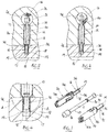
- Figure 1 illustrates a form of fastening element in which its sleeve is made of metal.
- the sleeve 10 is made out of sheet metal, for example steel, by die cutting and stamping or pressing.
- the sleeve 10 here is conveniently made in two individual parts 10a, 10b that can be fitted around the dowel 12.
- the two parts 10a, 10b are each in the form of a semi-cylindrical shell.
- Connectors, in this case snap tabs 24, enable the two parts 10a, 10b to attach together when they are in position on the dowel 12, so that the sleeve 10 and dowel together form an integral sub-assembly.
- the sleeve could of course be formed in other configurations, such as by means of a one-piece construction that is wrapped around the dowel, or using more than two individual parts. It could also be formed using a different metal, such as zinc, or a non-metal, such as carbon, or a hybrid composition from two or more different materials. Also, other processes such as die casting could be used in the formation of the sleeve.
- the dowel 12 here is of generally known form, with a head 13 at one end to be engaged by a rotatable camming device 14, an expander 15 at the other end, and a shank 11 extending between the two.
- the dowel 12 is conveniently made from rolled steel.
- the expander 15 is of generally known form, with a flared, bell-shaped end. The conical shape of the expander 15 effectively forms a reaction surface for the outward expansion of the sleeve 10.
- the dowel 12 here additionally has a flange 30 on its shank 11.
- the flange 30 is designed to engage the sleeve 10, in this case at the junction of its expandable section 16. Its purpose is to ensure that the sleeve 10 will be pushed fully into the face hole 17 when the sub-assembly is initially engaged in the panel 18.
- the dowel 12 could of course be formed out of different materials and in other ways, for example by die casting from zinc or fabricating from a non-metal such as carbon, or by combinations of different materials and forming processes.
- the sleeve 10 has two main sections. At one end is its expandable section 16: this is the part that fits into the face hole 17 in the first panel 18.
- the expandable section 16 here is formed with a number of axially extending slits 25, so that it is effectively split up into a number of individual fingers 26.
- the fingers 26 are designed to facilitate the expansion process. In this case, the sleeve 10 has four fingers 26, but the number could of course be more or less.
- the slits 25 extend substantially over the whole of the expandable section 16, terminating approximately at or just beyond its junction with the other main section 20 of the sleeve. This means that the length of the fingers 26 is approximately equal to the depth of the face hole 17 in the panel 18. What this means in practice is that in the expansion process, the fingers 26 will tend to flex with a hinging motion, as will be described in more detail below.
- each of the fingers 26 presents an outwardly facing cutting edge 19.
- the cutting edges 19 extend around the dowel 12 in an arcuate profile. They are designed to cut into the material of the panel 18 in the expansion process. They will not normally have to be specially sharpened for this purpose: the edge that results from simply cropping the fingers 26 in a die cutting process will usually be sufficient.
- the fingers 26 are crimped so that their free ends have a slight outward flare. This assists with presenting the cutting edges 19 so that they will cut effectively into the material in the expansion process. It also facilitates the sliding engagement of the fingers 26 on the expander 15 in the expansion process.
- the fingers 26 here otherwise give the expandable section 16 an essentially plain cylindrical outer profile.
- the expandable section 16 is designed to be readily insertable into the face hole 17 by hand, but to form a relatively snug fit within it.
- the other section 20 of the sleeve 10 is designed to fit in an edge hole 21 in the second panel 22.
- This section 20 also has an essentially plain cylindrical outer profile and is designed to be readily insertable into its hole 21 by hand, but to form a relatively snug fit within it.
- the edge hole 21 communicates with a face hole 23 in the second panel 22, with the face hole providing a mount for a rotatable camming device 14 to engage the head 13 of the dowel 12 in use.
- the free end of this section 20 of the sleeve 10 terminates in a reduced diameter section 27. In use, this section 27 abuts against the outer cylindrical surface of the camming element 14.
- Figures 3 and 4 show the consequence of this relative movement between the dowel 12 and the sleeve 10.
- the axial displacement of the expander 15 has forced the fingers 26 of the sleeve 10 to flex outwardly at their free ends, by the action of the expander 15 on the flared end of the fingers.
- the cutting edges 19 of the fingers 26 have been forced outwardly and hence caused to cut into the material of the panel 18.
- Figure 4 how the flexing of the fingers 26 resembles a hinging motion from a position approximately level with the face of the panel 18.
- the cutting edges 19 will penetrate into the material to a sufficient depth to prevent the possibility of the sleeve 10 being simply pulled out of the face hole 17.
- This provides a solid point of anchorage for the sleeve 10.
- the anchorage point is at a position as near to the bottom of the face hole 17 as possible.
- Panels used in flat pack furniture are typically made out of composite materials such as wood chip or the like. These typically contain voids between particulate matter and have little inherent strength.
- the aim in this particular design of dowel is to ensure that its point of engagement with the face hole in the panel will be at depth. It is also to ensure that the dowel engages the material with a positive interference fit. In this way, the effective pull-out resistance of the device is maximised. It may be preferable for the sleeve to present cutting edges at different axial positions, so as to cut into the material at different depths.
- Pull-out resistance is a measure of the pulling force that is needed to pull a dowel out of a panel and hence is an indication of the strength of a joint.
- Conventional expandable sleeve dowel designs feature ribs or barbs along the length of their sleeves, effectively creating a series of local interference fits with the material along the bore of the face hole.
- the pull-out resistance of these conventional designs is limited, however, because the friable nature of the material does not provide strong resistance to the possibility of the ribs or barbs simply pulling through.
- the form of fastener seen in Figure 5 is essentially similar to that shown in Figure 1 .
- the expandable section 51 of the sleeve 50 is not plain, but is provided with additional barbs 52.
- the sleeve 50 still comprises flexible fingers 53 with cutting edges 54 at their free ends that operate in the expansion process in the same manner as described above.
- the barbs 52 do not interfere with this operation. Instead, their purpose is to engage the bore of the face hole 17 in the panel 18 substantially throughout its depth and hence provide additional stability to the anchorage of the fastener in the panel.
- the camming device 60 is provided with a tapering groove 61 in its outer circumferential surface.
- the purpose of the groove 61 is to allow for a certain degree of axial displacement of the sleeve 50 during the joint forming process.
- initial rotation of the camming device 60 causes the expansion process to anchor the sleeve 50 in the face hole 17 in its panel 18, as seen in Figure 7 .
- Further rotation of the camming device 60 then pulls both the dowel 70 and the sleeve 50, thus pulling the panel 18 with it and hence creating a tight joint.
- Flat pack furniture is typically expected to be capable of being disassembled and re-assembled, so it is preferable to be able to extract the cams and/or dowels of the fasteners described above from their panels.
- the fingers of their sleeves would have to retract sufficiently for the cutting edges to clear the bore of the face hole. In practice, depending on materials used, this is unlikely to occur without special provision. Accordingly, to facilitate extraction, the fingers are preferably cut at a slight angle, rather than square, and at slightly spaced apart axial positions, in order that their cutting edges are effectively aligned along a helical path. This then allows the possibility for the dowel and sleeve to be "unscrewed" out of the face hole, with the cutting edges effectively cutting a helical groove in the bore of the face hole in the process, somewhat in the manner of a screw thread.
- a mechanism for urging retraction of the fingers of the sleeve to facilitate removal of the dowel from the face hole on disassembly for example by suitably configuring the sleeve at its point of engagement with the flange on the shank of the dowel.
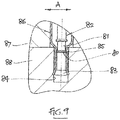
- a modification to the dowels described above is seen in Figure 9 .
- the modification comprises a flange 80 on the shank 81 of the dowel 82.
- the flange 80 is located on the lower section of the dowel 81.
- the flange 80 is spaced from the expander region 83 of the dowel 82 by a distance less than the depth of the face hole 84 in which the fastening element is located.
- the flange 80 is designed to engage the fingers 85 of the sleeve 86 near the entrance to the face hole 84 when the fastening element is in its set position (as seen in Figure 9 ).
- the purpose of the arrangement is to ensure that the fingers 85 of the sleeve 86 will fit snugly in the bore of the face hole 84. This eliminates or at least substantially reduces the possibility for lateral "play", ie transverse shearing movement between the two panels 87, 88 (illustrated by arrow A in Figure 9 ).
Description
- This invention relates to fastening elements for joint forming devices such as may be used in the furniture industry.
-
- According to the present invention there is provided a fastening element for use with a tightening element in a device for forming a joint between two panels, the fastening element being elongate and comprising a dowel having a head at one end and engaging said tightening element in use, an expander at the other end, and a shank extending therebetween, the fastening element further comprising a sleeve having an expandable section at one end extending over said expander, with the expander operatively engaging the sleeve in use to cause outward movement of its expandable section upon axial displacement of the dowel relative to the sleeve, the sleeve having at least one outwardly facing projection on its expandable section, with the expandable section of the sleeve being insertable into a face hole in a first one of the panels, with the projection on the sleeve being in the form of a cutting edge that extends around the dowel in an arcuate profile and that has sufficient strength to cut into the panel material in use of the device, with the cutting edge being provided at or near the end of the expandable section of the sleeve, with the expandable section of the sleeve comprising two or more individually moveable finger portions each with a cutting edge, with the finger portions being moveable hingedly from a position approximately level with the face of the first one of the panels, characterised in that the dowel comprises on its shank a first flange operable to engage the sleeve at the junction of its expandable section to ensure that the sleeve is pushed fully into the face hole and a second flange spaced from the expander section by a distance less than the depth of the face hole, such that said second flange engages the finger portions near the entrance to the face hole.
- By way of example, embodiments of the invention will now be described with reference to the accompanying drawings, in which:
-
Figure 1 shows in exploded view a first form of fastening element which is not according to the invention, -
Figure 2 is a cross-sectional view through a panel joint showing a device with the fastening element ofFigure 1 in its un-set condition, -
Figure 3 shows the panel joint ofFigure 2 in its set condition, -
Figure 4 is an enlarged detail ofFigure 3 , -
Figure 5 shows in exploded view a second form of fastening element which is not according to the invention, -
Figure 6 is a cross-sectional view through a panel joint showing a device with the fastening element ofFigure 5 in its un-set condition, -
Figure 7 shows the panel joint ofFigure 5 in a partially set condition, -
Figure 8 shows the panel joint ofFigure 5 in its fully set condition, and -
Figure 9 shows a modified form of dowel for the fastening elements ofFigures 1 and5 , which is according to the invention. - Devices are known for joining together panels, such as are used for assembly of furniture panels in factories or at home in furniture known as "flat pack" or "ready to assemble" or "knock down" furniture, and which typically comprise a tightening element in the form of a rotatable cam and a fastening element in the form of an elongate sleeved dowel. In such devices, the fastening element is anchorable at one end in a face hole in one panel, with the cam being mounted in a hole in the other panel and being operatively engageable with the head of the dowel at its other end. Conventionally, the dowels are formed of a metal pin, with an expandable sleeve, typically of plastics material, which can be set in the face hole by axial displacement of the dowel relative to the sleeve upon rotation of the cam.
-
Figure 1 illustrates a form of fastening element in which its sleeve is made of metal. In the preferred form, the sleeve 10 is made out of sheet metal, for example steel, by die cutting and stamping or pressing. To facilitate assembly, the sleeve 10 here is conveniently made in two individual parts 10a, 10b that can be fitted around the dowel 12. In this case, the two parts 10a, 10b are each in the form of a semi-cylindrical shell. Connectors, in this case snap tabs 24, enable the two parts 10a, 10b to attach together when they are in position on the dowel 12, so that the sleeve 10 and dowel together form an integral sub-assembly. - The sleeve could of course be formed in other configurations, such as by means of a one-piece construction that is wrapped around the dowel, or using more than two individual parts. It could also be formed using a different metal, such as zinc, or a non-metal, such as carbon, or a hybrid composition from two or more different materials. Also, other processes such as die casting could be used in the formation of the sleeve.
- The dowel 12 here is of generally known form, with a head 13 at one end to be engaged by a rotatable camming device 14, an expander 15 at the other end, and a shank 11 extending between the two. Here, the dowel 12 is conveniently made from rolled steel. The expander 15 is of generally known form, with a flared, bell-shaped end. The conical shape of the expander 15 effectively forms a reaction surface for the outward expansion of the sleeve 10.
- The dowel 12 here additionally has a flange 30 on its shank 11. The flange 30 is designed to engage the sleeve 10, in this case at the junction of its expandable section 16. Its purpose is to ensure that the sleeve 10 will be pushed fully into the face hole 17 when the sub-assembly is initially engaged in the panel 18.
- The dowel 12 could of course be formed out of different materials and in other ways, for example by die casting from zinc or fabricating from a non-metal such as carbon, or by combinations of different materials and forming processes.
- The sleeve 10 has two main sections. At one end is its expandable section 16: this is the part that fits into the face hole 17 in the first panel 18. The expandable section 16 here is formed with a number of axially extending slits 25, so that it is effectively split up into a number of individual fingers 26. The fingers 26 are designed to facilitate the expansion process. In this case, the sleeve 10 has four fingers 26, but the number could of course be more or less.
- The slits 25 extend substantially over the whole of the expandable section 16, terminating approximately at or just beyond its junction with the other main section 20 of the sleeve. This means that the length of the fingers 26 is approximately equal to the depth of the face hole 17 in the panel 18. What this means in practice is that in the expansion process, the fingers 26 will tend to flex with a hinging motion, as will be described in more detail below.
- At their free ends, each of the fingers 26 presents an outwardly facing cutting edge 19. The cutting edges 19 extend around the dowel 12 in an arcuate profile. They are designed to cut into the material of the panel 18 in the expansion process. They will not normally have to be specially sharpened for this purpose: the edge that results from simply cropping the fingers 26 in a die cutting process will usually be sufficient.
- The fingers 26 are crimped so that their free ends have a slight outward flare. This assists with presenting the cutting edges 19 so that they will cut effectively into the material in the expansion process. It also facilitates the sliding engagement of the fingers 26 on the expander 15 in the expansion process. The fingers 26 here otherwise give the expandable section 16 an essentially plain cylindrical outer profile.
- The expandable section 16 is designed to be readily insertable into the face hole 17 by hand, but to form a relatively snug fit within it.
- The other section 20 of the sleeve 10 is designed to fit in an edge hole 21 in the second panel 22. This section 20 also has an essentially plain cylindrical outer profile and is designed to be readily insertable into its hole 21 by hand, but to form a relatively snug fit within it.
- The edge hole 21 communicates with a face hole 23 in the second panel 22, with the face hole providing a mount for a rotatable camming device 14 to engage the head 13 of the dowel 12 in use. The free end of this section 20 of the sleeve 10 terminates in a reduced diameter section 27. In use, this section 27 abuts against the outer cylindrical surface of the camming element 14.
- In known manner, when the camming device 14 is rotated about its axis, its jaws 28 engage with the head 13 of the dowel 12 to cause axial displacement of the dowel in a direction away from the first panel 18. Since the sleeve 10 is in abutting engagement with the outer surface of the camming device 14, it is prevented from moving. The net result is relative axial movement between the dowel 12 and the sleeve 10.
-
Figures 3 and 4 show the consequence of this relative movement between the dowel 12 and the sleeve 10. As will be seen, the axial displacement of the expander 15 has forced the fingers 26 of the sleeve 10 to flex outwardly at their free ends, by the action of the expander 15 on the flared end of the fingers. In so doing, the cutting edges 19 of the fingers 26 have been forced outwardly and hence caused to cut into the material of the panel 18. It can be seen inFigure 4 how the flexing of the fingers 26 resembles a hinging motion from a position approximately level with the face of the panel 18. - It is intended that the cutting edges 19 will penetrate into the material to a sufficient depth to prevent the possibility of the sleeve 10 being simply pulled out of the face hole 17. This provides a solid point of anchorage for the sleeve 10. Ideally, the anchorage point is at a position as near to the bottom of the face hole 17 as possible.
- Panels used in flat pack furniture are typically made out of composite materials such as wood chip or the like. These typically contain voids between particulate matter and have little inherent strength. The aim in this particular design of dowel is to ensure that its point of engagement with the face hole in the panel will be at depth. It is also to ensure that the dowel engages the material with a positive interference fit. In this way, the effective pull-out resistance of the device is maximised. It may be preferable for the sleeve to present cutting edges at different axial positions, so as to cut into the material at different depths.
- Pull-out resistance is a measure of the pulling force that is needed to pull a dowel out of a panel and hence is an indication of the strength of a joint. Conventional expandable sleeve dowel designs feature ribs or barbs along the length of their sleeves, effectively creating a series of local interference fits with the material along the bore of the face hole. The pull-out resistance of these conventional designs is limited, however, because the friable nature of the material does not provide strong resistance to the possibility of the ribs or barbs simply pulling through.
- In the fastener described above, since the cutting edges 19 of the fingers 26 are designed to cut relatively deeply into the material and at a position at or near to the bottom of the face hole 17, there will be a significant depth of material between the point of anchorage of the fastener and the face of the panel 18. What this means in practice is that the fastener cannot be pulled out of the face hole 17 without causing significant disintegration of the panel 18. In particular, pull-out of the fastener will require a sizeable chunk of material to break away from the panel 18. In effect, therefore, the cutting edges act in the manner of a crack propagator, so that a typical failure mode will be along fracture lines A A shown in
Figure 4 . The net effect is that the pull-out resistance of the fastener is considerably greater than for a conventional fastener. - It will be appreciated that for the fastener described above to work effectively, the cutting edge that cuts into the panel has to be stronger than the panel material and to be able to maintain its configuration under stress. This will not normally be possible with conventional fasteners, where the sort of plastic sleeves that are typically used do not have sufficient strength or rigidity. Using a metal such as steel to fabricate the sleeve ensures that there will be sufficient strength and rigidity. However, it will be understood that other materials could equally well be used, even plastics, providing it is is of a grade with sufficient strength and rigidity.
- The form of fastener seen in
Figure 5 is essentially similar to that shown inFigure 1 . In this case, however, the expandable section 51 of the sleeve 50 is not plain, but is provided with additional barbs 52. The sleeve 50 still comprises flexible fingers 53 with cutting edges 54 at their free ends that operate in the expansion process in the same manner as described above. The barbs 52 do not interfere with this operation. Instead, their purpose is to engage the bore of the face hole 17 in the panel 18 substantially throughout its depth and hence provide additional stability to the anchorage of the fastener in the panel. - As will be seen in
Figures 6, 7 and 8 , another difference from the jointing device described above is in the design of the camming device 60. In this case, the camming device 60 is provided with a tapering groove 61 in its outer circumferential surface. The purpose of the groove 61 is to allow for a certain degree of axial displacement of the sleeve 50 during the joint forming process. In known manner, initial rotation of the camming device 60 causes the expansion process to anchor the sleeve 50 in the face hole 17 in its panel 18, as seen inFigure 7 . Further rotation of the camming device 60 then pulls both the dowel 70 and the sleeve 50, thus pulling the panel 18 with it and hence creating a tight joint. - Flat pack furniture is typically expected to be capable of being disassembled and re-assembled, so it is preferable to be able to extract the cams and/or dowels of the fasteners described above from their panels. For the dowels to be capable of being pulled out of their face holes, the fingers of their sleeves would have to retract sufficiently for the cutting edges to clear the bore of the face hole. In practice, depending on materials used, this is unlikely to occur without special provision. Accordingly, to facilitate extraction, the fingers are preferably cut at a slight angle, rather than square, and at slightly spaced apart axial positions, in order that their cutting edges are effectively aligned along a helical path. This then allows the possibility for the dowel and sleeve to be "unscrewed" out of the face hole, with the cutting edges effectively cutting a helical groove in the bore of the face hole in the process, somewhat in the manner of a screw thread.
- Alternatively, or in addition, it might be possible to include a mechanism for urging retraction of the fingers of the sleeve to facilitate removal of the dowel from the face hole on disassembly, for example by suitably configuring the sleeve at its point of engagement with the flange on the shank of the dowel.
- According to the invention, a modification to the dowels described above is seen in
Figure 9 . The modification comprises a flange 80 on the shank 81 of the dowel 82. As will be seen, the flange 80 is located on the lower section of the dowel 81. Specifically, the flange 80 is spaced from the expander region 83 of the dowel 82 by a distance less than the depth of the face hole 84 in which the fastening element is located. The flange 80 is designed to engage the fingers 85 of the sleeve 86 near the entrance to the face hole 84 when the fastening element is in its set position (as seen inFigure 9 ). The purpose of the arrangement is to ensure that the fingers 85 of the sleeve 86 will fit snugly in the bore of the face hole 84. This eliminates or at least substantially reduces the possibility for lateral "play", ie transverse shearing movement between the two panels 87, 88 (illustrated by arrow A inFigure 9 ).
Claims (13)
- A fastening element for use with a tightening element in a device for forming a joint between two panels, the fastening element being elongate and comprising a dowel (12) having a head (13) at one end and engaging said tightening element in use, an expander (15) at the other end, and a shank (11) extending therebetween, the fastening element further comprising a sleeve (10) having an expandable section (16) at one end extending over said expander, with the expander operatively engaging the sleeve in use to cause outward movement of its expandable section upon axial displacement of the dowel relative to the sleeve, the sleeve having at least one outwardly facing projection on its expandable section, with the expandable section of the sleeve being insertable into a face hole (17) in a first one of the panels (18), with the projection on the sleeve (10) being in the form of a cutting edge (19) that extends around the dowel (12) in an arcuate profile and that has sufficient strength to cut into the panel material in use of the device, with the cutting edge (19) being provided at or near the end of the expandable section (16) of the sleeve (10), with the expandable section (16) of the sleeve (10) comprising two or more individually moveable finger portions (26) each with a cutting edge (19), with the finger portions (26) being moveable hingedly from a position approximately level with the face of the first one of the panels (18), characterised in that the dowel (12) comprises on its shank (11) a first flange (30) operable to engage the sleeve (10) at the junction of its expandable section to ensure that the sleeve (10) is pushed fully into the face hole (17) and a second flange (80) spaced from the expander section (16) by a distance less than the depth of the face hole (17), such that said second flange engages the finger portions (26) near the entrance to the face hole (17).
- A fastening element as claimed in claim 1 wherein the end of the expandable section (16) of the sleeve (10) has an outward flare.
- A fastening element as claimed in claim 1 or claim 2 wherein the cutting edges (19) of the fingers (26) are at different axial positions on the sleeve (10).
- A fastening element as claimed in claim 3 wherein the cutting edges (19) are set at an inclined angle, so that they are effectively aligned along one or more helical paths.
- A fastening element as claimed in any preceding claim wherein apart from the cutting edge (19), the expandable section (16) of the sleeve (10) has an essentially plain outer profile.
- A fastening element as claimed in claim 5 wherein the essentially plain outer profile of the expandable section (16) of the sleeve (10) is cylindrical.
- A fastening element as claimed in any preceding claim wherein the sleeve (10) is insertable at its other end into an edge hole in the second of the panels (22) for engagement of the head (13) of the dowel (12) with the tightening element in use.
- A fastening element as claimed in claim 7 and comprising a reaction surface for holding the axial position of the sleeve (10) relative to the second panel (22) upon tightening of the device in use.
- A fastening element as claimed in claim 8 wherein said reaction surface is provided by an outer camming surface (60) of the tightening device, with the sleeve (10) being in abutting engagement with it.
- A fastening element as claimed in any preceding claim wherein the sleeve (10) is formed in two or more individual parts.
- A fastening element as claimed in claim 10 wherein the individual parts of the sleeve (10) comprise means for connecting them together so that the fastening element is able to form an integral sub-assembly.
- A fastening element as claimed in any preceding claim wherein the sleeve (10) is made of metal.
- A fastening element as claimed in claim 12 wherein the sleeve (10) is made by die-cutting and stamping or pressing.
Applications Claiming Priority (2)
| Application Number | Priority Date | Filing Date | Title |
|---|---|---|---|
| GB201422164 | 2014-12-12 | ||
| PCT/EP2015/079501 WO2016092105A1 (en) | 2014-12-12 | 2015-12-11 | Improvements in joint forming devices |
Publications (2)
| Publication Number | Publication Date |
|---|---|
| EP3230603A1 EP3230603A1 (en) | 2017-10-18 |
| EP3230603B1 true EP3230603B1 (en) | 2021-01-20 |
Family
ID=54848588
Family Applications (1)
| Application Number | Title | Priority Date | Filing Date |
|---|---|---|---|
| EP15808250.3A Active EP3230603B1 (en) | 2014-12-12 | 2015-12-11 | Improvements in joint forming devices |
Country Status (9)
| Country | Link |
|---|---|
| US (1) | US10495125B2 (en) |
| EP (1) | EP3230603B1 (en) |
| JP (1) | JP6768659B2 (en) |
| CN (1) | CN107407310B (en) |
| AU (1) | AU2015359285B2 (en) |
| BR (1) | BR112017012296A2 (en) |
| ES (1) | ES2862136T3 (en) |
| RU (1) | RU2700022C2 (en) |
| WO (1) | WO2016092105A1 (en) |
Families Citing this family (2)
| Publication number | Priority date | Publication date | Assignee | Title |
|---|---|---|---|---|
| ITUB20151914A1 (en) * | 2015-07-07 | 2017-01-07 | Leonardo Srl | MINIMUM VISIBILITY JUNCTION DEVICE FOR FURNITURE PARTS AND FURNISHING ITEMS |
| GB2564080A (en) | 2017-04-25 | 2019-01-09 | Titus D O O Dekani | Improvements in joint forming devices |
Citations (1)
| Publication number | Priority date | Publication date | Assignee | Title |
|---|---|---|---|---|
| GB2357327A (en) * | 1999-12-16 | 2001-06-20 | Miguel Angel Rioja Calvo | A furniture panel connection device |
Family Cites Families (19)
| Publication number | Priority date | Publication date | Assignee | Title |
|---|---|---|---|---|
| US3730568A (en) * | 1971-03-15 | 1973-05-01 | F Giovannetti | Connector |
| AT330405B (en) * | 1974-11-29 | 1976-06-25 | Lehmann Kg Oskar | FITTING FOR DETACHABLE CONNECTION ANGLED, IN PARTICULAR RECTANGULAR EQUIPMENT WALLS OR DGL. |
| DE2625182C3 (en) * | 1976-03-11 | 1980-06-19 | Richard Heinze Gmbh & Co Kg, 4900 Herford | Fitting for the detachable connection of two components, in particular panel-shaped components for furniture |
| DE2702643C3 (en) * | 1976-06-04 | 1980-09-18 | Richard Heinze Gmbh & Co Kg, 4900 Herford | Fitting for the detachable connection of two vertically abutting components, especially furniture parts |
| DE3204737C1 (en) * | 1982-02-11 | 1983-04-14 | Häfele KG, 7270 Nagold | Detachable connection of two panels perpendicular to each other, preferably furniture panels |
| US5375923A (en) * | 1993-06-16 | 1994-12-27 | Fieldstone Cabinetry, Inc. | Drawer front attachment system |
| GB2305226B (en) * | 1993-12-23 | 1997-07-16 | Titus Int Plc | Joint forming device |
| US5810505A (en) * | 1996-07-26 | 1998-09-22 | Kimball International, Inc. | Double threaded fastener system |
| CN1123702C (en) * | 1997-03-11 | 2003-10-08 | 提托斯国际公开有限公司 | Joint forming device |
| BR9806196A (en) * | 1997-05-01 | 1999-11-16 | Titus Int Plc | Cam arrangement element, and device for forming a joint between two members |
| DE60208218T2 (en) * | 2001-09-26 | 2006-08-17 | Agostino Ferrari S.P.A. | DEVICE AND METHOD FOR THE DETACHABLE CONNECTION OF INTERLOCKING LOAD-BEARING PARTS AND PULL-MEMBER FOR USE IN MANUFACTURING THE DEVICE |
| DE20118279U1 (en) * | 2001-11-09 | 2002-01-31 | Haefele Gmbh & Co | Link between two components |
| RU2268406C2 (en) * | 2004-02-02 | 2006-01-20 | Иван Владимирович Мышко | Universal coupling device |
| DE202004013378U1 (en) * | 2004-08-25 | 2004-12-16 | Hettich-Heinze Gmbh & Co. Kg | Insert pivot for fixing furniture fitments has two semi-cylindrical identical parts with adjoining dividing faces having corresponding detent noses and recesses |
| GB2430991B (en) * | 2005-10-07 | 2008-09-10 | Titus Int Plc | Improvements in joint forming devices |
| GB2443425B (en) * | 2006-11-01 | 2010-11-03 | Titus Int Plc | Improvements in fasteners |
| DE102009043179B8 (en) * | 2009-09-26 | 2016-12-22 | Franz Baur | connecting device |
| CN202381478U (en) * | 2011-12-02 | 2012-08-15 | 杨征宇 | Multifunctional rapid-assembly connector for furniture |
| DE102012219154A1 (en) * | 2012-10-19 | 2014-05-08 | Confitt Gmbh | Detachable connection device for tool-free installation |
-
2015
- 2015-12-11 WO PCT/EP2015/079501 patent/WO2016092105A1/en active Application Filing
- 2015-12-11 RU RU2017124454A patent/RU2700022C2/en active
- 2015-12-11 EP EP15808250.3A patent/EP3230603B1/en active Active
- 2015-12-11 CN CN201580067542.3A patent/CN107407310B/en active Active
- 2015-12-11 AU AU2015359285A patent/AU2015359285B2/en active Active
- 2015-12-11 BR BR112017012296A patent/BR112017012296A2/en active Search and Examination
- 2015-12-11 US US15/534,512 patent/US10495125B2/en active Active
- 2015-12-11 ES ES15808250T patent/ES2862136T3/en active Active
- 2015-12-11 JP JP2017531145A patent/JP6768659B2/en active Active
Patent Citations (1)
| Publication number | Priority date | Publication date | Assignee | Title |
|---|---|---|---|---|
| GB2357327A (en) * | 1999-12-16 | 2001-06-20 | Miguel Angel Rioja Calvo | A furniture panel connection device |
Also Published As
| Publication number | Publication date |
|---|---|
| RU2700022C2 (en) | 2019-09-12 |
| US10495125B2 (en) | 2019-12-03 |
| AU2015359285B2 (en) | 2019-07-25 |
| EP3230603A1 (en) | 2017-10-18 |
| JP6768659B2 (en) | 2020-10-14 |
| ES2862136T3 (en) | 2021-10-07 |
| AU2015359285A1 (en) | 2017-06-29 |
| RU2017124454A (en) | 2019-01-14 |
| US20170363125A1 (en) | 2017-12-21 |
| CN107407310B (en) | 2020-09-11 |
| RU2017124454A3 (en) | 2019-03-28 |
| BR112017012296A2 (en) | 2018-04-24 |
| JP2018506000A (en) | 2018-03-01 |
| CN107407310A (en) | 2017-11-28 |
| WO2016092105A1 (en) | 2016-06-16 |
Similar Documents
| Publication | Publication Date | Title |
|---|---|---|
| EP1817504B1 (en) | Self-drilling hollow wall anchor | |
| US7896594B2 (en) | Self-drilling masonry bolt | |
| US20150219136A1 (en) | Push Fastener | |
| EP2808567A1 (en) | Anchor assembly with toggle for hollow walls | |
| WO2015118702A1 (en) | Bolt provided with locking function | |
| EP3230603B1 (en) | Improvements in joint forming devices | |
| US20100221065A1 (en) | Handle connector for hand tool or utensil | |
| EP2661564B1 (en) | A dowel for a crumbly supporting material | |
| EP2824250B1 (en) | Dowel head for the fixture of an insulation board | |
| KR102536722B1 (en) | Minifix for furniture panel assembly with improved structure | |
| GB2576956A (en) | Dowel fasteners | |
| KR200485838Y1 (en) | Anchor Bolt for Fixing Wall | |
| EP3577350A1 (en) | Gypsum plasterboard dowel | |
| EP1158186A1 (en) | Polygonal rivet with an internal threading | |
| WO2019056025A1 (en) | Expansion assembly | |
| AU2012101316A4 (en) | A fastener | |
| WO2016005901A1 (en) | Fastener | |
| RU2575374C2 (en) | Insulation material holder | |
| JP3158399U (en) | Anchor bolt | |
| WO2020002303A1 (en) | Fastening device | |
| CN111542704A (en) | Improvements in or relating to fasteners | |
| WO2017112962A1 (en) | Fastener | |
| WO2018206933A1 (en) | Fixing device |
Legal Events
| Date | Code | Title | Description |
|---|---|---|---|
| STAA | Information on the status of an ep patent application or granted ep patent |
Free format text: STATUS: THE INTERNATIONAL PUBLICATION HAS BEEN MADE |
|
| PUAI | Public reference made under article 153(3) epc to a published international application that has entered the european phase |
Free format text: ORIGINAL CODE: 0009012 |
|
| STAA | Information on the status of an ep patent application or granted ep patent |
Free format text: STATUS: REQUEST FOR EXAMINATION WAS MADE |
|
| 17P | Request for examination filed |
Effective date: 20170615 |
|
| AK | Designated contracting states |
Kind code of ref document: A1 Designated state(s): AL AT BE BG CH CY CZ DE DK EE ES FI FR GB GR HR HU IE IS IT LI LT LU LV MC MK MT NL NO PL PT RO RS SE SI SK SM TR |
|
| AX | Request for extension of the european patent |
Extension state: BA ME |
|
| DAV | Request for validation of the european patent (deleted) | ||
| DAX | Request for extension of the european patent (deleted) | ||
| STAA | Information on the status of an ep patent application or granted ep patent |
Free format text: STATUS: EXAMINATION IS IN PROGRESS |
|
| 17Q | First examination report despatched |
Effective date: 20180615 |
|
| GRAP | Despatch of communication of intention to grant a patent |
Free format text: ORIGINAL CODE: EPIDOSNIGR1 |
|
| STAA | Information on the status of an ep patent application or granted ep patent |
Free format text: STATUS: GRANT OF PATENT IS INTENDED |
|
| INTG | Intention to grant announced |
Effective date: 20200116 |
|
| GRAJ | Information related to disapproval of communication of intention to grant by the applicant or resumption of examination proceedings by the epo deleted |
Free format text: ORIGINAL CODE: EPIDOSDIGR1 |
|
| STAA | Information on the status of an ep patent application or granted ep patent |
Free format text: STATUS: EXAMINATION IS IN PROGRESS |
|
| RAP1 | Party data changed (applicant data changed or rights of an application transferred) |
Owner name: TITUS D.O.O. DEKANI |
|
| INTC | Intention to grant announced (deleted) | ||
| GRAP | Despatch of communication of intention to grant a patent |
Free format text: ORIGINAL CODE: EPIDOSNIGR1 |
|
| STAA | Information on the status of an ep patent application or granted ep patent |
Free format text: STATUS: GRANT OF PATENT IS INTENDED |
|
| INTG | Intention to grant announced |
Effective date: 20200710 |
|
| GRAS | Grant fee paid |
Free format text: ORIGINAL CODE: EPIDOSNIGR3 |
|
| GRAA | (expected) grant |
Free format text: ORIGINAL CODE: 0009210 |
|
| STAA | Information on the status of an ep patent application or granted ep patent |
Free format text: STATUS: THE PATENT HAS BEEN GRANTED |
|
| AK | Designated contracting states |
Kind code of ref document: B1 Designated state(s): AL AT BE BG CH CY CZ DE DK EE ES FI FR GB GR HR HU IE IS IT LI LT LU LV MC MK MT NL NO PL PT RO RS SE SI SK SM TR |
|
| REG | Reference to a national code |
Ref country code: GB Ref legal event code: FG4D |
|
| REG | Reference to a national code |
Ref country code: CH Ref legal event code: EP |
|
| REG | Reference to a national code |
Ref country code: DE Ref legal event code: R096 Ref document number: 602015065009 Country of ref document: DE |
|
| REG | Reference to a national code |
Ref country code: AT Ref legal event code: REF Ref document number: 1356644 Country of ref document: AT Kind code of ref document: T Effective date: 20210215 |
|
| REG | Reference to a national code |
Ref country code: IE Ref legal event code: FG4D |
|
| REG | Reference to a national code |
Ref country code: NL Ref legal event code: MP Effective date: 20210120 |
|
| REG | Reference to a national code |
Ref country code: LT Ref legal event code: MG9D |
|
| REG | Reference to a national code |
Ref country code: AT Ref legal event code: MK05 Ref document number: 1356644 Country of ref document: AT Kind code of ref document: T Effective date: 20210120 |
|
| PG25 | Lapsed in a contracting state [announced via postgrant information from national office to epo] |
Ref country code: BG Free format text: LAPSE BECAUSE OF FAILURE TO SUBMIT A TRANSLATION OF THE DESCRIPTION OR TO PAY THE FEE WITHIN THE PRESCRIBED TIME-LIMIT Effective date: 20210420 Ref country code: FI Free format text: LAPSE BECAUSE OF FAILURE TO SUBMIT A TRANSLATION OF THE DESCRIPTION OR TO PAY THE FEE WITHIN THE PRESCRIBED TIME-LIMIT Effective date: 20210120 Ref country code: GR Free format text: LAPSE BECAUSE OF FAILURE TO SUBMIT A TRANSLATION OF THE DESCRIPTION OR TO PAY THE FEE WITHIN THE PRESCRIBED TIME-LIMIT Effective date: 20210421 Ref country code: HR Free format text: LAPSE BECAUSE OF FAILURE TO SUBMIT A TRANSLATION OF THE DESCRIPTION OR TO PAY THE FEE WITHIN THE PRESCRIBED TIME-LIMIT Effective date: 20210120 Ref country code: NO Free format text: LAPSE BECAUSE OF FAILURE TO SUBMIT A TRANSLATION OF THE DESCRIPTION OR TO PAY THE FEE WITHIN THE PRESCRIBED TIME-LIMIT Effective date: 20210420 Ref country code: PT Free format text: LAPSE BECAUSE OF FAILURE TO SUBMIT A TRANSLATION OF THE DESCRIPTION OR TO PAY THE FEE WITHIN THE PRESCRIBED TIME-LIMIT Effective date: 20210520 Ref country code: LT Free format text: LAPSE BECAUSE OF FAILURE TO SUBMIT A TRANSLATION OF THE DESCRIPTION OR TO PAY THE FEE WITHIN THE PRESCRIBED TIME-LIMIT Effective date: 20210120 |
|
| PG25 | Lapsed in a contracting state [announced via postgrant information from national office to epo] |
Ref country code: SE Free format text: LAPSE BECAUSE OF FAILURE TO SUBMIT A TRANSLATION OF THE DESCRIPTION OR TO PAY THE FEE WITHIN THE PRESCRIBED TIME-LIMIT Effective date: 20210120 Ref country code: AT Free format text: LAPSE BECAUSE OF FAILURE TO SUBMIT A TRANSLATION OF THE DESCRIPTION OR TO PAY THE FEE WITHIN THE PRESCRIBED TIME-LIMIT Effective date: 20210120 Ref country code: PL Free format text: LAPSE BECAUSE OF FAILURE TO SUBMIT A TRANSLATION OF THE DESCRIPTION OR TO PAY THE FEE WITHIN THE PRESCRIBED TIME-LIMIT Effective date: 20210120 Ref country code: LV Free format text: LAPSE BECAUSE OF FAILURE TO SUBMIT A TRANSLATION OF THE DESCRIPTION OR TO PAY THE FEE WITHIN THE PRESCRIBED TIME-LIMIT Effective date: 20210120 Ref country code: RS Free format text: LAPSE BECAUSE OF FAILURE TO SUBMIT A TRANSLATION OF THE DESCRIPTION OR TO PAY THE FEE WITHIN THE PRESCRIBED TIME-LIMIT Effective date: 20210120 |
|
| PG25 | Lapsed in a contracting state [announced via postgrant information from national office to epo] |
Ref country code: IS Free format text: LAPSE BECAUSE OF FAILURE TO SUBMIT A TRANSLATION OF THE DESCRIPTION OR TO PAY THE FEE WITHIN THE PRESCRIBED TIME-LIMIT Effective date: 20210520 |
|
| REG | Reference to a national code |
Ref country code: ES Ref legal event code: FG2A Ref document number: 2862136 Country of ref document: ES Kind code of ref document: T3 Effective date: 20211007 |
|
| REG | Reference to a national code |
Ref country code: DE Ref legal event code: R097 Ref document number: 602015065009 Country of ref document: DE |
|
| PG25 | Lapsed in a contracting state [announced via postgrant information from national office to epo] |
Ref country code: CZ Free format text: LAPSE BECAUSE OF FAILURE TO SUBMIT A TRANSLATION OF THE DESCRIPTION OR TO PAY THE FEE WITHIN THE PRESCRIBED TIME-LIMIT Effective date: 20210120 Ref country code: EE Free format text: LAPSE BECAUSE OF FAILURE TO SUBMIT A TRANSLATION OF THE DESCRIPTION OR TO PAY THE FEE WITHIN THE PRESCRIBED TIME-LIMIT Effective date: 20210120 Ref country code: SM Free format text: LAPSE BECAUSE OF FAILURE TO SUBMIT A TRANSLATION OF THE DESCRIPTION OR TO PAY THE FEE WITHIN THE PRESCRIBED TIME-LIMIT Effective date: 20210120 |
|
| PLBE | No opposition filed within time limit |
Free format text: ORIGINAL CODE: 0009261 |
|
| STAA | Information on the status of an ep patent application or granted ep patent |
Free format text: STATUS: NO OPPOSITION FILED WITHIN TIME LIMIT |
|
| PG25 | Lapsed in a contracting state [announced via postgrant information from national office to epo] |
Ref country code: DK Free format text: LAPSE BECAUSE OF FAILURE TO SUBMIT A TRANSLATION OF THE DESCRIPTION OR TO PAY THE FEE WITHIN THE PRESCRIBED TIME-LIMIT Effective date: 20210120 Ref country code: SK Free format text: LAPSE BECAUSE OF FAILURE TO SUBMIT A TRANSLATION OF THE DESCRIPTION OR TO PAY THE FEE WITHIN THE PRESCRIBED TIME-LIMIT Effective date: 20210120 Ref country code: RO Free format text: LAPSE BECAUSE OF FAILURE TO SUBMIT A TRANSLATION OF THE DESCRIPTION OR TO PAY THE FEE WITHIN THE PRESCRIBED TIME-LIMIT Effective date: 20210120 |
|
| 26N | No opposition filed |
Effective date: 20211021 |
|
| PG25 | Lapsed in a contracting state [announced via postgrant information from national office to epo] |
Ref country code: AL Free format text: LAPSE BECAUSE OF FAILURE TO SUBMIT A TRANSLATION OF THE DESCRIPTION OR TO PAY THE FEE WITHIN THE PRESCRIBED TIME-LIMIT Effective date: 20210120 |
|
| PG25 | Lapsed in a contracting state [announced via postgrant information from national office to epo] |
Ref country code: SI Free format text: LAPSE BECAUSE OF FAILURE TO SUBMIT A TRANSLATION OF THE DESCRIPTION OR TO PAY THE FEE WITHIN THE PRESCRIBED TIME-LIMIT Effective date: 20210120 |
|
| PG25 | Lapsed in a contracting state [announced via postgrant information from national office to epo] |
Ref country code: IS Free format text: LAPSE BECAUSE OF FAILURE TO SUBMIT A TRANSLATION OF THE DESCRIPTION OR TO PAY THE FEE WITHIN THE PRESCRIBED TIME-LIMIT Effective date: 20210520 |
|
| PGFP | Annual fee paid to national office [announced via postgrant information from national office to epo] |
Ref country code: ES Payment date: 20220103 Year of fee payment: 7 |
|
| PG25 | Lapsed in a contracting state [announced via postgrant information from national office to epo] |
Ref country code: MC Free format text: LAPSE BECAUSE OF FAILURE TO SUBMIT A TRANSLATION OF THE DESCRIPTION OR TO PAY THE FEE WITHIN THE PRESCRIBED TIME-LIMIT Effective date: 20210120 |
|
| REG | Reference to a national code |
Ref country code: CH Ref legal event code: PL |
|
| REG | Reference to a national code |
Ref country code: BE Ref legal event code: MM Effective date: 20211231 |
|
| PG25 | Lapsed in a contracting state [announced via postgrant information from national office to epo] |
Ref country code: LU Free format text: LAPSE BECAUSE OF NON-PAYMENT OF DUE FEES Effective date: 20211211 Ref country code: IE Free format text: LAPSE BECAUSE OF NON-PAYMENT OF DUE FEES Effective date: 20211211 |
|
| PG25 | Lapsed in a contracting state [announced via postgrant information from national office to epo] |
Ref country code: BE Free format text: LAPSE BECAUSE OF NON-PAYMENT OF DUE FEES Effective date: 20211231 |
|
| PG25 | Lapsed in a contracting state [announced via postgrant information from national office to epo] |
Ref country code: LI Free format text: LAPSE BECAUSE OF NON-PAYMENT OF DUE FEES Effective date: 20211231 Ref country code: CH Free format text: LAPSE BECAUSE OF NON-PAYMENT OF DUE FEES Effective date: 20211231 |
|
| PG25 | Lapsed in a contracting state [announced via postgrant information from national office to epo] |
Ref country code: HU Free format text: LAPSE BECAUSE OF FAILURE TO SUBMIT A TRANSLATION OF THE DESCRIPTION OR TO PAY THE FEE WITHIN THE PRESCRIBED TIME-LIMIT; INVALID AB INITIO Effective date: 20151211 |
|
| P01 | Opt-out of the competence of the unified patent court (upc) registered |
Effective date: 20230411 |
|
| PG25 | Lapsed in a contracting state [announced via postgrant information from national office to epo] |
Ref country code: NL Free format text: LAPSE BECAUSE OF NON-PAYMENT OF DUE FEES Effective date: 20210120 Ref country code: CY Free format text: LAPSE BECAUSE OF FAILURE TO SUBMIT A TRANSLATION OF THE DESCRIPTION OR TO PAY THE FEE WITHIN THE PRESCRIBED TIME-LIMIT Effective date: 20210120 |
|
| PGFP | Annual fee paid to national office [announced via postgrant information from national office to epo] |
Ref country code: GB Payment date: 20231207 Year of fee payment: 9 |
|
| REG | Reference to a national code |
Ref country code: ES Ref legal event code: FD2A Effective date: 20240129 |
|
| PGFP | Annual fee paid to national office [announced via postgrant information from national office to epo] |
Ref country code: TR Payment date: 20231129 Year of fee payment: 9 Ref country code: IT Payment date: 20231129 Year of fee payment: 9 Ref country code: FR Payment date: 20231215 Year of fee payment: 9 Ref country code: DE Payment date: 20231215 Year of fee payment: 9 |
|
| PG25 | Lapsed in a contracting state [announced via postgrant information from national office to epo] |
Ref country code: ES Free format text: LAPSE BECAUSE OF NON-PAYMENT OF DUE FEES Effective date: 20221212 |