EP3230585B1 - Wire element arrangement in an energy recovery device - Google Patents
Wire element arrangement in an energy recovery device Download PDFInfo
- Publication number
- EP3230585B1 EP3230585B1 EP15832797.3A EP15832797A EP3230585B1 EP 3230585 B1 EP3230585 B1 EP 3230585B1 EP 15832797 A EP15832797 A EP 15832797A EP 3230585 B1 EP3230585 B1 EP 3230585B1
- Authority
- EP
- European Patent Office
- Prior art keywords
- sma
- energy recovery
- wires
- nte
- friction fit
- Prior art date
- Legal status (The legal status is an assumption and is not a legal conclusion. Google has not performed a legal analysis and makes no representation as to the accuracy of the status listed.)
- Active
Links
- 238000011084 recovery Methods 0.000 title claims description 34
- 229910001285 shape-memory alloy Inorganic materials 0.000 claims description 85
- 239000000463 material Substances 0.000 claims description 30
- 230000007246 mechanism Effects 0.000 claims description 12
- 230000006835 compression Effects 0.000 claims description 8
- 238000007906 compression Methods 0.000 claims description 8
- 210000004907 gland Anatomy 0.000 claims description 6
- 230000004888 barrier function Effects 0.000 claims description 4
- 238000000034 method Methods 0.000 description 29
- 229910001000 nickel titanium Inorganic materials 0.000 description 21
- HZEWFHLRYVTOIW-UHFFFAOYSA-N [Ti].[Ni] Chemical compound [Ti].[Ni] HZEWFHLRYVTOIW-UHFFFAOYSA-N 0.000 description 16
- 230000008602 contraction Effects 0.000 description 16
- 238000006073 displacement reaction Methods 0.000 description 13
- 229910045601 alloy Inorganic materials 0.000 description 12
- 239000000956 alloy Substances 0.000 description 12
- 239000012530 fluid Substances 0.000 description 10
- 238000004519 manufacturing process Methods 0.000 description 10
- 230000005540 biological transmission Effects 0.000 description 9
- 230000033001 locomotion Effects 0.000 description 8
- 238000012546 transfer Methods 0.000 description 7
- 239000007787 solid Substances 0.000 description 6
- 230000007423 decrease Effects 0.000 description 5
- HLXZNVUGXRDIFK-UHFFFAOYSA-N nickel titanium Chemical group [Ti].[Ti].[Ti].[Ti].[Ti].[Ti].[Ti].[Ti].[Ti].[Ti].[Ti].[Ni].[Ni].[Ni].[Ni].[Ni].[Ni].[Ni].[Ni].[Ni].[Ni].[Ni].[Ni].[Ni].[Ni] HLXZNVUGXRDIFK-UHFFFAOYSA-N 0.000 description 5
- 238000012856 packing Methods 0.000 description 5
- 238000013461 design Methods 0.000 description 4
- 229910052751 metal Inorganic materials 0.000 description 4
- 239000002184 metal Substances 0.000 description 4
- 150000003839 salts Chemical class 0.000 description 4
- XLYOFNOQVPJJNP-UHFFFAOYSA-N water Substances O XLYOFNOQVPJJNP-UHFFFAOYSA-N 0.000 description 4
- 230000008901 benefit Effects 0.000 description 3
- 238000010438 heat treatment Methods 0.000 description 3
- 230000008450 motivation Effects 0.000 description 3
- 238000012545 processing Methods 0.000 description 3
- XEEYBQQBJWHFJM-UHFFFAOYSA-N Iron Chemical compound [Fe] XEEYBQQBJWHFJM-UHFFFAOYSA-N 0.000 description 2
- 229910000831 Steel Inorganic materials 0.000 description 2
- 238000004873 anchoring Methods 0.000 description 2
- 238000001816 cooling Methods 0.000 description 2
- -1 copper-zinc-aluminium-nickel Chemical compound 0.000 description 2
- 230000000694 effects Effects 0.000 description 2
- 238000005516 engineering process Methods 0.000 description 2
- 230000006870 function Effects 0.000 description 2
- 229920000642 polymer Polymers 0.000 description 2
- 230000008569 process Effects 0.000 description 2
- 239000010959 steel Substances 0.000 description 2
- 239000002699 waste material Substances 0.000 description 2
- RYGMFSIKBFXOCR-UHFFFAOYSA-N Copper Chemical compound [Cu] RYGMFSIKBFXOCR-UHFFFAOYSA-N 0.000 description 1
- 239000004677 Nylon Substances 0.000 description 1
- 229920000147 Styrene maleic anhydride Polymers 0.000 description 1
- HCHKCACWOHOZIP-UHFFFAOYSA-N Zinc Chemical compound [Zn] HCHKCACWOHOZIP-UHFFFAOYSA-N 0.000 description 1
- 238000005275 alloying Methods 0.000 description 1
- 239000004411 aluminium Substances 0.000 description 1
- 229910052782 aluminium Inorganic materials 0.000 description 1
- XAGFODPZIPBFFR-UHFFFAOYSA-N aluminium Chemical compound [Al] XAGFODPZIPBFFR-UHFFFAOYSA-N 0.000 description 1
- 238000002399 angioplasty Methods 0.000 description 1
- 238000013459 approach Methods 0.000 description 1
- 239000000919 ceramic Substances 0.000 description 1
- 229910010293 ceramic material Inorganic materials 0.000 description 1
- 238000004891 communication Methods 0.000 description 1
- 230000002508 compound effect Effects 0.000 description 1
- 229910052802 copper Inorganic materials 0.000 description 1
- 239000010949 copper Substances 0.000 description 1
- 238000005260 corrosion Methods 0.000 description 1
- 230000007797 corrosion Effects 0.000 description 1
- 230000001186 cumulative effect Effects 0.000 description 1
- 125000004122 cyclic group Chemical group 0.000 description 1
- 230000001351 cycling effect Effects 0.000 description 1
- 230000001419 dependent effect Effects 0.000 description 1
- 238000011161 development Methods 0.000 description 1
- 239000013013 elastic material Substances 0.000 description 1
- PCHJSUWPFVWCPO-UHFFFAOYSA-N gold Chemical compound [Au] PCHJSUWPFVWCPO-UHFFFAOYSA-N 0.000 description 1
- 229910052737 gold Inorganic materials 0.000 description 1
- 239000010931 gold Substances 0.000 description 1
- 238000007654 immersion Methods 0.000 description 1
- 238000009434 installation Methods 0.000 description 1
- 229910052742 iron Inorganic materials 0.000 description 1
- 239000007788 liquid Substances 0.000 description 1
- 238000012423 maintenance Methods 0.000 description 1
- 229920001778 nylon Polymers 0.000 description 1
- 238000010248 power generation Methods 0.000 description 1
- 230000004044 response Effects 0.000 description 1
- 238000004513 sizing Methods 0.000 description 1
- 125000006850 spacer group Chemical group 0.000 description 1
- 239000010935 stainless steel Substances 0.000 description 1
- 229910001220 stainless steel Inorganic materials 0.000 description 1
- 238000001356 surgical procedure Methods 0.000 description 1
- 230000009466 transformation Effects 0.000 description 1
- 229910052725 zinc Inorganic materials 0.000 description 1
- 239000011701 zinc Substances 0.000 description 1
Images


Classifications
-
- F—MECHANICAL ENGINEERING; LIGHTING; HEATING; WEAPONS; BLASTING
- F03—MACHINES OR ENGINES FOR LIQUIDS; WIND, SPRING, OR WEIGHT MOTORS; PRODUCING MECHANICAL POWER OR A REACTIVE PROPULSIVE THRUST, NOT OTHERWISE PROVIDED FOR
- F03G—SPRING, WEIGHT, INERTIA OR LIKE MOTORS; MECHANICAL-POWER PRODUCING DEVICES OR MECHANISMS, NOT OTHERWISE PROVIDED FOR OR USING ENERGY SOURCES NOT OTHERWISE PROVIDED FOR
- F03G7/00—Mechanical-power-producing mechanisms, not otherwise provided for or using energy sources not otherwise provided for
- F03G7/06—Mechanical-power-producing mechanisms, not otherwise provided for or using energy sources not otherwise provided for using expansion or contraction of bodies due to heating, cooling, moistening, drying or the like
- F03G7/061—Mechanical-power-producing mechanisms, not otherwise provided for or using energy sources not otherwise provided for using expansion or contraction of bodies due to heating, cooling, moistening, drying or the like characterised by the actuating element
- F03G7/0614—Mechanical-power-producing mechanisms, not otherwise provided for or using energy sources not otherwise provided for using expansion or contraction of bodies due to heating, cooling, moistening, drying or the like characterised by the actuating element using shape memory elements
-
- D—TEXTILES; PAPER
- D07—ROPES; CABLES OTHER THAN ELECTRIC
- D07B—ROPES OR CABLES IN GENERAL
- D07B5/00—Making ropes or cables from special materials or of particular form
-
- D—TEXTILES; PAPER
- D07—ROPES; CABLES OTHER THAN ELECTRIC
- D07B—ROPES OR CABLES IN GENERAL
- D07B1/00—Constructional features of ropes or cables
- D07B1/06—Ropes or cables built-up from metal wires, e.g. of section wires around a hemp core
- D07B1/0673—Ropes or cables built-up from metal wires, e.g. of section wires around a hemp core having a rope configuration
-
- E—FIXED CONSTRUCTIONS
- E01—CONSTRUCTION OF ROADS, RAILWAYS, OR BRIDGES
- E01D—CONSTRUCTION OF BRIDGES, ELEVATED ROADWAYS OR VIADUCTS; ASSEMBLY OF BRIDGES
- E01D19/00—Structural or constructional details of bridges
- E01D19/16—Suspension cables; Cable clamps for suspension cables ; Pre- or post-stressed cables
-
- F—MECHANICAL ENGINEERING; LIGHTING; HEATING; WEAPONS; BLASTING
- F03—MACHINES OR ENGINES FOR LIQUIDS; WIND, SPRING, OR WEIGHT MOTORS; PRODUCING MECHANICAL POWER OR A REACTIVE PROPULSIVE THRUST, NOT OTHERWISE PROVIDED FOR
- F03G—SPRING, WEIGHT, INERTIA OR LIKE MOTORS; MECHANICAL-POWER PRODUCING DEVICES OR MECHANISMS, NOT OTHERWISE PROVIDED FOR OR USING ENERGY SOURCES NOT OTHERWISE PROVIDED FOR
- F03G7/00—Mechanical-power-producing mechanisms, not otherwise provided for or using energy sources not otherwise provided for
- F03G7/06—Mechanical-power-producing mechanisms, not otherwise provided for or using energy sources not otherwise provided for using expansion or contraction of bodies due to heating, cooling, moistening, drying or the like
- F03G7/061—Mechanical-power-producing mechanisms, not otherwise provided for or using energy sources not otherwise provided for using expansion or contraction of bodies due to heating, cooling, moistening, drying or the like characterised by the actuating element
- F03G7/06114—Mechanical-power-producing mechanisms, not otherwise provided for or using energy sources not otherwise provided for using expansion or contraction of bodies due to heating, cooling, moistening, drying or the like characterised by the actuating element using the thermal expansion or contraction of solid materials
-
- F—MECHANICAL ENGINEERING; LIGHTING; HEATING; WEAPONS; BLASTING
- F03—MACHINES OR ENGINES FOR LIQUIDS; WIND, SPRING, OR WEIGHT MOTORS; PRODUCING MECHANICAL POWER OR A REACTIVE PROPULSIVE THRUST, NOT OTHERWISE PROVIDED FOR
- F03G—SPRING, WEIGHT, INERTIA OR LIKE MOTORS; MECHANICAL-POWER PRODUCING DEVICES OR MECHANISMS, NOT OTHERWISE PROVIDED FOR OR USING ENERGY SOURCES NOT OTHERWISE PROVIDED FOR
- F03G7/00—Mechanical-power-producing mechanisms, not otherwise provided for or using energy sources not otherwise provided for
- F03G7/06—Mechanical-power-producing mechanisms, not otherwise provided for or using energy sources not otherwise provided for using expansion or contraction of bodies due to heating, cooling, moistening, drying or the like
- F03G7/065—Mechanical-power-producing mechanisms, not otherwise provided for or using energy sources not otherwise provided for using expansion or contraction of bodies due to heating, cooling, moistening, drying or the like using a shape memory element
-
- F—MECHANICAL ENGINEERING; LIGHTING; HEATING; WEAPONS; BLASTING
- F03—MACHINES OR ENGINES FOR LIQUIDS; WIND, SPRING, OR WEIGHT MOTORS; PRODUCING MECHANICAL POWER OR A REACTIVE PROPULSIVE THRUST, NOT OTHERWISE PROVIDED FOR
- F03G—SPRING, WEIGHT, INERTIA OR LIKE MOTORS; MECHANICAL-POWER PRODUCING DEVICES OR MECHANISMS, NOT OTHERWISE PROVIDED FOR OR USING ENERGY SOURCES NOT OTHERWISE PROVIDED FOR
- F03G7/00—Mechanical-power-producing mechanisms, not otherwise provided for or using energy sources not otherwise provided for
- F03G7/08—Mechanical-power-producing mechanisms, not otherwise provided for or using energy sources not otherwise provided for recovering energy derived from swinging, rolling, pitching or like movements, e.g. from the vibrations of a machine
-
- D—TEXTILES; PAPER
- D07—ROPES; CABLES OTHER THAN ELECTRIC
- D07B—ROPES OR CABLES IN GENERAL
- D07B2201/00—Ropes or cables
- D07B2201/20—Rope or cable components
- D07B2201/2001—Wires or filaments
- D07B2201/2009—Wires or filaments characterised by the materials used
-
- D—TEXTILES; PAPER
- D07—ROPES; CABLES OTHER THAN ELECTRIC
- D07B—ROPES OR CABLES IN GENERAL
- D07B2205/00—Rope or cable materials
- D07B2205/30—Inorganic materials
- D07B2205/3021—Metals
- D07B2205/3085—Alloys, i.e. non ferrous
-
- F—MECHANICAL ENGINEERING; LIGHTING; HEATING; WEAPONS; BLASTING
- F05—INDEXING SCHEMES RELATING TO ENGINES OR PUMPS IN VARIOUS SUBCLASSES OF CLASSES F01-F04
- F05B—INDEXING SCHEME RELATING TO WIND, SPRING, WEIGHT, INERTIA OR LIKE MOTORS, TO MACHINES OR ENGINES FOR LIQUIDS COVERED BY SUBCLASSES F03B, F03D AND F03G
- F05B2280/00—Materials; Properties thereof
- F05B2280/50—Intrinsic material properties or characteristics
- F05B2280/5006—Shape memory
Definitions
- the present application relates to the field of energy recovery and in particular to the use of Shape-Memory Alloys (SMA) or Negative Thermal Expansion (NTE) materials for the same.
- SMA Shape-Memory Alloys
- NTE Negative Thermal Expansion
- a Shape Memory Alloy is an alloy that "remembers" its original, cold-forged shape which once deformed returns to its pre-deformed shape upon heating.
- This material is a lightweight, solid-state alternative to conventional actuators such as hydraulic, pneumatic, and motor-based systems.
- shape-memory alloys are the copper-zinc-aluminium-nickel, copper-aluminium-nickel, and nickel-titanium (NiTi) alloys but SMAs can also be created, for example, by alloying zinc, copper, gold and iron or using other suitable elements.
- At least one SMA or NTE element is swaged at one end to create a mechanical barrier to prevent slippage of the element in use.
- the energy recovery device comprises a friction fit device.
- the device comprises a chuck adapted to secure the SMA or NTE elements in a friction fit configuration.
- the chuck comprises a clamp and an adjuster configured to adjust the force applied to the SMA or NTE elements.
- the energy recovery device comprises a friction fit device wherein the device comprises a chain adapted to be tensioned around the SMA or NTE elements using a shackle.
- a friction fit device wherein the device comprises a spring clip to ensure the SMA or NTE elements are tightly packed together.
- the spring clip comprises a stiff material wrapped in a circular fashion and fitted back through a slot.
- a friction fit device wherein the device comprises a clamp adapted to secure the SMA or NTE elements in a friction fit configuration wherein the clamp is biased by at least one spring to force the clamp around the SMA or NTE elements.
- a friction fit device wherein the device comprises a cable gland to secure the SMA or NTE elements in a friction fit configuration.
- a friction fit device wherein the device comprises a pressurised elastic tubular ring to secure the NTE elements in a friction fit configuration.
- the elastic tubular ring is inflatable.
- a friction fit device wherein the device comprises a compression ring configured to retain the SMA or NTE elements in position.
- the device comprises at least one groove support.
- the groove support serves the function of increasing the surface area to enhance the frictional bond between the bundle holder and the wire elements immediately adjacant to the holder.
- the grooves can also serve to guide the wires and ensure that interference between adjacant wires is minimised.
- At least one SMA or NTE element comprises a threaded wire.
- the threaded wire comprises a straight helical thread or a tapered helical thread.
- a plurality of wire elements for use in an energy recovery device comprising Shape Memory Alloy or other Negative Thermal Expansion (NTE) Material, wherein at least one wire element is fixed at one end and free to move at a second end, such that the wire elements are arranged adjacently and are in friction or interference contact with each other and are secured at the outer perimeter of wires utilising a securing means.
- NTE Negative Thermal Expansion
- the invention relates to a heat recovery system under development which can use either Shape-Memory Alloys (SMA) or Negative Thermal Expansion materials (NTE) to generate power from low grade heat.
- SMA Shape-Memory Alloys
- NTE Negative Thermal Expansion materials
- the SMA engine 1 comprises an SMA actuation core.
- the SMA actuation core is comprised of SMA material clamped or otherwise secured at a first point which is fixed. At the opposing end, the SMA material is clamped or otherwise secured to a drive mechanism 2. Thus whilst the first point is anchored the second point is free to move albeit pulling the drive mechanism 3.
- An immersion chamber 4 adapted for housing the SMA engine and is adapted to be sequentially filled with fluid to allow heating and/or cooling of the SMA engine. Accordingly, as heat is applied to the SMA core it is free to contract.
- the SMA core comprises a plurality of parallel wires, ribbons or sheets of SMA material.
- a deflection in and around 4% is common for such a core.
- a linear movement of approximately 4 cm to be available can also be obtained.
- the force that is provided depends on the mass of wire used.
- Such an energy recovery device is described in PCT Patent Publication number WO2013/087490 , assigned to the assignee of the present invention, and is incorporated fully herein by reference.
- NiTi Nickel-Titanium alloy
- This alloy is a well-known Shape-Memory Alloy and has numerous uses across different industries.
- the wire's extremities have to be presented in such a way that they are able to be securely fixed in a metallic support, hereinafter referred to as a bundle holder.
- Nickel-Titanium alloy NiTi
- This alloy is a well-known Shape Memory Alloy and has numerous uses across different industries.
- the NiTi wires form the working element of the engine. Force is generated through the contraction and expansion of these elements within the working core, via a piston and a mechanical/hydraulic transmission system. In one embodiment a piston and crank mechanism could be used. An important aspect of this system is the ability to secure the NiTi elements at both ends such that a strong and reliable union is created, enabling high-force, low displacement work to be performed for a maximum number of working cycles.
- Figure 2 illustrates a friction fit method to ensure the close packing of the working wires, according to a first aspect of the invention.
- the wires 10 are grouped together and clamped using a bracket mechanism 20.
- the bracket may be constructed from metal or otherwise and is compressed around the wire bundle in such a way as to allow any force exerted on or by the wires to be transmitted through the bracket by way of a frictional or interference fit.
- this bracket keeps the wires closely packed whilst also enabling the transmission of force through the friction fit of the bracket and the wires. Close-packing of the wires in this manner provides advantages for minimizing the total size of the system and for ensuring compact realisation of the energy recovery device.
- the embodiment enables the fixing of the SMA or NiTi wires in such a way that the high force developed by their contraction can be safely transmitted such that mechanical work can be produced.
- a Shape-Memory Alloy (SMA) or Negative Thermal Expansion (NTE) material will contract not only longitudinally (along a central axis) but also laterally (in the diametrical plane). It is foreseeable, therefore, that any bundle of working elements comprised of such material would likely encounter shrinkage in the lateral direction. This shrinkage can have negative implications for the integrity of a friction-based fixing system, as the loss of the cross sectional area of the bundle, however small, would enable a relaxation of the frictional bond, thus enabling slippage or total loss of adhesion.
- SMA Shape-Memory Alloy
- NTE Negative Thermal Expansion
- FIG. 3 One embodiment that avoids this is illustrated in Figure 3 .
- Swages or flares are added to the terminal ends of the wires 10.
- a simple swage system 11 creates a mechanical barrier to the slippage of the wire element through a designated guide hole in the bundle holder.
- each wire has its own individual guide hole, giving rise to a "salt shaker" type bundle holder system whereby a solid plate of material is pierced many times (however many wires are required in the given engine) to enable a given number of wires to be utilised in the engine.
- the swage provides a mechanical barrier itself, with the force of the contraction transmitted directly through the interface of the swage and the bundle holder.
- This embodiment enables the NiTi wires to be fixed in such a way that the high force developed by their contraction can be safely transmitted such that mechanical work can be produced.
- NiTi Nickel-Titanium alloy
- This alloy is a well-known Shape Memory Alloy and has numerous uses across different industries.
- Nitinol core In order for a Nitinol core to actuate a piston a method must be identified for fixing a bundle of wires so that one end is fixed to the top of the core and the other end is attached to the piston.
- a friction fit is one possible way of securing wires together. Basically a friction fit is where the roughness of two surfaces is used to prevent slippage or movement of an object. The effectiveness of the fit is determined by the coefficient of friction for each surface, the area of contact and the pressure between the surfaces.
- Figure 4 shows a method of securing a bundle of wires by means of friction fitting.
- the friction fit is created by a device which works in a similar manner to a pillar drill chuck.
- a standard chuck is designed only to holder one piece of material.
- the chuck comprises two components: a clamp 30 and an adjuster 31.
- the adjuster is made of one single circular piece while the clamp can consist of several units in order to increase surface contact with the wire bundle.
- the adjuster is connected to the clamp by an angled threaded section. When the adjuster is rotated in a clockwise manner it causes the angled section of the clamp to move down.
- the clamp also has a vertically flat section which is parallel with the bundle of wire. As the angled section moves down it causes the flat section to move horizontally which applies a force on the outer surface of the bundle. The result is that the individual wires are pushed together increasing the friction between them and with enough applied force, preventing individual wires from being pulled from the bundle.
- the main advantage of this embodiment is that the chuck allows for the force applied on the bundle to be manually adjusted by means of a tool such as a chuck key.
- the chuck can be made of materials which have high corrosion resistance in water such as stainless steel or aluminium. Greasing the threads on the clamp and adjuster can also combat against the unit seizing up.
- NiTi Nickel-Titanium alloy
- This alloy is a well-known Shape Memory Alloy and has numerous uses across different industries.
- This alloy presented as a plurality of wires
- the most important aspect of this system is the ability to secure the NiTi elements at both ends such that a reliable assembly is created, enabling high-force, low displacement work to be performed for a maximum number of working cycles.
- Nitinol core In order for a Nitinol core to actuate a piston a method must be identified for fixing a bundle of wires so that one end is fixed to the top of the core and the other end is attached to the piston.
- a friction fit is one possible way of securing wires together. Basically a friction fit is where the roughness of two surfaces is used to prevent slippage or movement of an object. The effectiveness of the fit is determined by the coefficient of friction for each surface, the area of contact and the pressure between the surfaces.
- Figure 5 show a concept 40 for creating a friction fit between a bundle of wires with the purpose of preventing any wire from being removed during service due to a vertical force.
- a chain 41 is provided which is made from a steel or other material.
- a shackle 42 Connected to the chain is a shackle 42 of a size allowing the chain to be fully passed through.
- This embodiment allows a friction fit to be created by wrapping the chain around the bundle and then passing it though a shackle.
- the chain passed through the shackle is tensioned so as to force the wires together and therefore increase the friction between them.
- a locking pin is placed through the bore of the chain which is closest to the shackle. This prevents the chain from pulling through the shackle therefore maintaining the tension in the chain.
- This embodiment reduces the steps required in manufacturing a bundle as the wire simply has to be cut. Also this method allows for the bundle of wires to be opened quickly by removing the pin which would reduce the time required to remove or insert wires during service.
- Nitinol core In order for a Nitinol core to actuate a piston a method must be identified for fixing a bundle of wires so that one end is fixed to the top of the core and the other end is attached to the piston.
- a friction fit is one possible way of securing wires together. Basically a friction fit is where the roughness of two surfaces is used to prevent slippage or movement of an object. The effectiveness of the fit is determined by the coefficient of friction for each surface, the area of contact and the pressure between the surfaces.
- Figure 6 illustrates a method of creating a friction fit for the purpose of holding two or more solid/ hollow wires together.
- a spring clip 50 can be adapted to grip and hold the ends of the wires together in a tight fit arrangement.
- a spring clip 50 is typically a continuous piece of stiff elastic material that is wrapped in a circular fashion and fitted back through a slot. Each end consists of a vertical adjusting point. When these points are pulled together it causes the diameter of the clip to increase. In order to create a friction fit between the bundles of wires, the bundle would be packed into the clip when it has been extended to the larger diameter. When in position, the adjustment points are released which causes the diameter to decrease. The decrease in diameter causes the clip to force the wires together and therefore increase the friction between each wire. The force applied to the wire bundle is determined by the elastic stiffness of the material used in the clip. If the force is high enough this will prevent individual wires from pulling out during operation.
- the advantage with this method is that as the wire diameter decrease when phase transformation occur, the clip will also decrease its inner radius and therefore maintain a force to holder the bundle together.
- a friction fit is one possible way of securing wires together. Basically a friction fit is where the roughness of two surfaces is used to prevent slippage or movement of an object. The effectiveness of the fit is determined by the coefficient of friction for each surface, the area of contact and the pressure between the surfaces.
- Figure 7 shows another embodiment for creating a friction fit.
- This embodiment is based on the previously discussed chuck concept.
- This concept creates a friction fit by using at least one clamp 60 to press in against the outer surface of the wire bundle, similar to the chuck concept.
- the clamps are manually adjusted which creates a potential risk of the chuck becoming loose during service or accidentally being left loose during maintenance.
- FIG. 7 a top view is also illustrated where three clamps are used to contact the bundle. During installation, the clamps 60 are pulled back and held. The bundle is then inserted to the core. Once in position the clamps are released where they enclose the outside of the bundle. The force applied is dependent on the stiffness of the springs used.
- This embodiment provides a solution to an issue involved in securing Shape Memory Alloy (SMA) wire in way which does not require the individual positioning of the wires during bundle assembly.
- Current methods employed involved the use of "salt shaker" embodiments, which consisted of a metal plate with an individual hole drilled for each wire contained in a bundle. This method entails lengthy manual assembly times which cause large lead times and costs during assembly.
- the embodiment discussed herein describe a method of securing bundles of wires whereby the order in which the wires are installed can be random, thereby allowing more autonomous and faster assembly of the SMA wire bundles.
- This embodiment also provides a method of bundle securement which can eliminate the need for swaged or domed wires, whereby the friction forces applied on the wire is enough to secure it. This would be advantageous against the salt shaker concept as it would remove a step of SMA wire processing thereby reducing manufacturing costs.
- This embodiment involves the use of a cable gland 70 for securing the wire bundles together. Cable glands are typically used to secure electrical wire into a container in order to prevent external environments affecting the internal electrical components. This embodiment proposes an alternate use for this device.
- the cable gland component is illustrated in Figure 8 , and consists of two pieces: the base 71 and cap 72.
- the base 71 component consists of flexible fins 73 or teeth and a threaded feature 74.
- the cap 72 can be seen to contain a matching female tread to the base, as well as a tapered internal geometry. When rotated onto the base, the lowering cap causes the fins to be forced radially towards each other. These closing teeth, which may have a lining to increase friction, are used to secure wire which runs through the hollow centre. This operation is illustrated in Figure 9 .
- Figure 10 shows the device in this application of securing wire bundles together.
- This alloy presented as a plurality of wires
- This alloy presented as a plurality of wires
- the most important aspect of this system is the ability to secure the wire elements at both ends such that a reliable assembly is created, enabling high-force, low displacement work to be performed for a maximum number of working cycles.
- the embodiment provides a solution to an issue involved in securing Shape Memory Alloy (SMA) wire in a way which does not require the individual positioning of the wires during bundle assembly.
- Current methods employed involved the use of "salt shaker" embodiments, which consists of a metal plate with an individual hole drilled for each wire contained in a bundle. This method entails lengthy manual assembly times which cause large lead times and costs during assembly.
- This embodiment provides a method of securing bundles of wires whereby the order in which the wires are installed can be random, thereby allowing more autonomous and faster assembly of the SMA wire bundles.
- This embodiment also provides a method of bundle securement which may eliminate the need for swaged or domed wires, whereby the friction forces applied on the wire are enough to secure it. This is advantageous as it removes a step of SMA wire processing thereby reducing manufacturing costs.
- This embodiment involves the use of pressurised air or fluid and an elastic tubular ring 80 in order to secure wire bundles together 10.
- this ring When deflated, this ring will have a greater inner diameter than the ring when it is fully inflated. This property can secure the wires by placing the wires tightly within the ring pre-inflation. At this point, inflation of the ring will cause a radial pressure to be applied to the wires contained within its centre, resulting in them being secured in place by friction.
- Fig 11 illustrates the operation of this embodiment.
- 81 shows the ring in its deflated state and 82 shows the ring in its inflated state.
- the ring is shown to be taller and thinner initially. However, with the introduction of pressure, the ring decreases in height as well as increasing its width and tubular thickness. This is primarily illustrated in plan view 83 and 84 above, where t is this thickness before inflation and T is thickness after. It can be stated that T>t in this example, and the ring would be suitable to be used to secure a Nitinol bundle in its inner diameter. This is illustrated in Fig 12 showing a plan view of the wires secured by the substantially tubular ring 81, 82.
- the material with which the ring is manufactured should be resilient enough to withstand the force required to secure the wire, while being elastic enough to provide the desired displacement needed to increase its inner diameter.
- One material could be nylon, which can provide these attributes, similar to attributes in the application of angioplasty (heart) balloons used in key-hole surgeries. It can also be advantageous to construct a container for this ring, which would restrict its outer diameter expansion, further providing more force/displacement to its inner expansion.
- the container can also be useful when loading the wire bundles pre inflation as it provides a solid guide as opposed to the relatively flexible inflatable ring. This is shown in Figure 13 and 14 , where the embodiment is shown with and without the wire bundle respectively.
- This alloy presented as a plurality of wires
- This alloy presented as a plurality of wires
- the most important aspect of this system is the ability to secure the wire elements at both ends such that a reliable assembly is created, enabling high-force, low displacement work to be performed for a maximum number of working cycles.
- This embodiment provides a method of bundle securement which can obviate the need for swaged or domed wires, whereby the friction forces applied on the wire is enough to secure it. This is advantageous as it removes a step of SMA wire processing thereby reducing manufacturing costs, in addition to being constructed of non-complicated parts.
- a method of securing a bundle of wires can be realised through the use of straight brackets 90, screws, and nuts.
- the brackets would be used to provide a force on the wires 10 through the tightening of the screw.
- These brackets can also have a secondary function as spacers.
- Figure 15 illustrates a number of views of such an embodiment where top (a) and side (b) & (c) views are shown.
- the brackets act as clamps, increasing the force exerted onto the Nitinol wires as the screw is turned and tightened.
- the embodiment is advantageous as it allows a large number of wires to be secured at once and does not require complicated parts.
- the surface of the bracket which comes in contact with the SMA wire may also be roughened in order to increase the frictional force applied and hence further secure the wires. After securing the wires using this method, the bundle may be held in place within a core using a holder slot 100, as shown in Fig 16 .
- This alloy presented as a plurality of wires
- This alloy presented as a plurality of wires
- the most important aspect of this system is the ability to secure the wire elements at both ends such that a reliable assembly is created, enabling high-force, low displacement work to be performed for a maximum number of working cycles.
- the bundle holder must overcome some specific problems:
- the following is a method to grip groups of wires in a bundle under loading conditions without the need to manufacture complex parts that can also be used on wires that have been domed or swaged on both ends.
- a metal ring 110 can be placed around a group of wires and a press then used to compress the ring around the wires which would then form a tight and compact bundle. This arrangement does not allow one wire to pass by another because of the domes 111 or swages 111 being slightly wider than the rest of the wire, as shown in Figure 17 and 18 .
- the compression ring acts to retain the wires in position, and maintains a gap between the wires that is smaller than the diameter of the swage or dome at any stage. This prevents pull through.
- the compound effect under loading is the radial transmission of the applied load onto the compression ring which can be designed to sit on a frame.
- a polymer, rubber or ceramic based liquid capable of setting to a solid form can be initially applied to the wires. When set, the wires are held in place. The compression ring is then applied to the outside of the newly set solid and compressed, as shown in Figure 18 . The polymer/rubber/ceramic material is non-load bearing, and the load is again transferred radially onto the compression ring.
- the bundle holder must overcome some specific problems:
- the wires can be mounted on support parts that have a number of grooves 120.
- the grooves have a double role:
- Figure 19 is a schematic of the grooved support 120 for the SMA wires and of the clamps (a) in the open position and (b) in the closed position.
- the clamps can have additional elastic tensioners on the inside to ensure that the wires will not get loose with time.
- the bottom part of the support is wide so it can split the wires and improve the heat transfer.
- the support can be mounted in a plate used as a bundle holder.
- This embodiment solves the problem of swaging wires individually and it would use a tightening element with elastic tensioning elements to fix them into place.
- the bundle holder design is solving many of the inherited problems of fixing together the wires, while keeping its structural integrity intact.
- the bundle holder consists of a plurality of threaded wires fixed together and placed tightly into a tapered hole and split collet arrangement. The treads act to maintain a good contact in between the wires and not allow them to slip from the bundle while cycling.
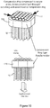
- Fig. 20 presents types of threads 130 for the SMA wire 10: a) straight helical thread 131; b) tapered helical thread 132.
- Fig. 21 illustrates a plurality of threaded SMA wires 140 in a bundle. When a force is applied to the wires in the bundle, the split collet and taper compact the threads together.
- Fig. 22 illustrates the SMA wires in a tapered collet, illustrated by the reference numeral 150.
- the diameter of the thread is selected so that the thinnest part of the structure would be the engaged part of the wire (the section immersed in cold/hot fluid) that is immediately below the thread.
- the length of wire interacting with the fluid flow is drawn or rolled to a smaller diameter, hence a gap between the wires is introduced to facilitate fluid flow.
- the reduced diameter can be optimised to allow for the optimum heat transfer between the fluid and SMA wires.
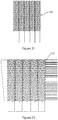
- Figure 23a & 23b illustrates a number of threaded wire designs according to another embodiment 160.
- the ends of the wire 161 are threaded and butted in order for them to be implemented in a compression bundle fitting, as illustrated in Figure 23a .
- a thread is formed along the full length 162 of the wire, as shown in Figure 23b .
- the thread increases the surface area of the wire, as well as increase turbulence along this surface during cyclic heating and cooling via a working fluid. This increased surface area and turbulence will serve to increase the thermodynamic performance of the wires.
- a method of reducing this effect can be to optimise wire layout within the wire bundle whereby the outer wires of the bundle would be smooth (where the working fluid can transfer heat easily), and the inner wires would have the threaded lengths as they would be hardest to reach during heat transfer to the entire bundle.
- a step further to this is to have a gradual increase in the sizing of the threads, where the outer wires begin smooth but gradually have deeper threads as the wires progress to the centre.
- Figure 24 illustrates an embodiment of a core with a plurality of SMA wires 10 arranged in parallel in use in an energy recovery device.
- the core is housed in a chamber and is connected to a fluid source via valves 170 and manifolds 171, 172.
- the SMA wires 10 are secured at both ends by a bottom and top bundle holder 172 and 173.
- One end of the core is in communication with a piston 174 that is moveable in response to expansion and contraction of the SMA wires to generate energy.
- the terms "comprise, comprises, comprised and comprising” or any variation thereof and the terms include, includes, included and including" or any variation thereof are considered to be totally interchangeable and they should all be afforded the widest possible interpretation and vice versa.
Landscapes
- Engineering & Computer Science (AREA)
- Chemical & Material Sciences (AREA)
- Combustion & Propulsion (AREA)
- Mechanical Engineering (AREA)
- General Engineering & Computer Science (AREA)
- Civil Engineering (AREA)
- Architecture (AREA)
- Structural Engineering (AREA)
- Sealing Devices (AREA)
- Shafts, Cranks, Connecting Bars, And Related Bearings (AREA)
- Wire Processing (AREA)
- Clamps And Clips (AREA)
- Vibration Prevention Devices (AREA)
- Ropes Or Cables (AREA)
Description
- The present application relates to the field of energy recovery and in particular to the use of Shape-Memory Alloys (SMA) or Negative Thermal Expansion (NTE) materials for the same.
- Low-grade heat, which is typically considered less than 100 degrees, represents a significant waste energy stream in industrial processes, power generation and transport applications. Recovery and re-use of such waste streams is desirable. An example of a technology which has been proposed for this purpose is a Thermoelectric Generator (TEG). Unfortunately, TEGs are relatively expensive. Another largely experimental approach that has been proposed to recover such energy is the use of Shape Memory Alloys.
- A Shape Memory Alloy (SMA) is an alloy that "remembers" its original, cold-forged shape which once deformed returns to its pre-deformed shape upon heating. This material is a lightweight, solid-state alternative to conventional actuators such as hydraulic, pneumatic, and motor-based systems.
- The three main types of shape-memory alloys are the copper-zinc-aluminium-nickel, copper-aluminium-nickel, and nickel-titanium (NiTi) alloys but SMAs can also be created, for example, by alloying zinc, copper, gold and iron or using other suitable elements.
- The memory of such materials has been employed or proposed since the early 1970s for use in heat recovery processes and in particular by constructing SMA engines which recover energy from heat as motion. Recent publications relating to energy recovery devices include
PCT Patent Publication number WO2013/087490 , assigned to the assignee of the present invention. Other patent publications in the art includeUS4,306,415 (Hochstein ) andUS2005/150223 (United Technologies). It is desirable to translate the contraction of the SMA or NTE material into a mechanical force in an efficient manner. It is also desirable to position and design the SMA or NTE material in an efficient way. It is not a trivial task and generally is complicated and involves significant energy losses.
It is therefore an object to provide an improved system and method in an energy recovery device. - According to the invention there is provided, as set out in the appended claims, an energy recovery device according to
claim 1. - In one embodiment at least one SMA or NTE element is swaged at one end to create a mechanical barrier to prevent slippage of the element in use.
- In one embodiment the energy recovery device comprises a friction fit device. In one embodiment the device comprises a chuck adapted to secure the SMA or NTE elements in a friction fit configuration.
- In one embodiment the chuck comprises a clamp and an adjuster configured to adjust the force applied to the SMA or NTE elements.
- In one embodiment the energy recovery device comprises a friction fit device wherein the device comprises a chain adapted to be tensioned around the SMA or NTE elements using a shackle.
- In one embodiment there is provided a friction fit device wherein the device comprises a spring clip to ensure the SMA or NTE elements are tightly packed together.
- In one embodiment the spring clip comprises a stiff material wrapped in a circular fashion and fitted back through a slot.
- In one embodiment there is provided a friction fit device wherein the device comprises a clamp adapted to secure the SMA or NTE elements in a friction fit configuration wherein the clamp is biased by at least one spring to force the clamp around the SMA or NTE elements.
- In one embodiment there is provided a friction fit device wherein the device comprises a cable gland to secure the SMA or NTE elements in a friction fit configuration.
- In one embodiment there is provided a friction fit device wherein the device comprises a pressurised elastic tubular ring to secure the NTE elements in a friction fit configuration.
- In one embodiment the elastic tubular ring is inflatable.
- In one embodiment there is provided a friction fit device wherein the device comprises a compression ring configured to retain the SMA or NTE elements in position.
- In one embodiment the device comprises at least one groove support. The groove support serves the function of increasing the surface area to enhance the frictional bond between the bundle holder and the wire elements immediately adjacant to the holder. The grooves can also serve to guide the wires and ensure that interference between adjacant wires is minimised.
- In one embodiment at least one SMA or NTE element comprises a threaded wire.
- In one embodiment the threaded wire comprises a straight helical thread or a tapered helical thread.
- In another embodiment there is provided a plurality of wire elements for use in an energy recovery device comprising Shape Memory Alloy or other Negative Thermal Expansion (NTE) Material, wherein at least one wire element is fixed at one end and free to move at a second end, such that the wire elements are arranged adjacently and are in friction or interference contact with each other and are secured at the outer perimeter of wires utilising a securing means.
- The invention will be more clearly understood from the following description of an embodiment thereof, given by way of example only, with reference to the accompanying drawings, in which:-
-
Figure 1 illustrates an exemplary energy recovery device using SMA or NTE materials; -
Figure 2 illustrates a first embodiment of the present invention showing how SMA or NTE wires can be secured using a friction fitting; -
Figure 3 illustrates a first embodiment of the present invention showing how SMA or NTE wires can be secured with a swaged fitting; -
Figure 4 illustrates a method of securing a bundle of wires by means of friction fitting, for example using a chuck; -
Figure 5 illustrates an embodiment for creating a friction fit between a bundle of wires with the purpose of preventing any wire from being removed during service due to a vertical force; -
Figure 6 illustrates a method of creating a friction fit for the purpose of holding two or more solid/ hollow wires together; -
Figure 7 illustrates a method of securing a bundle of wires by means of friction fitting, for example using a spring based chuck; -
Figures 8, 9 & 10 illustrate use of a cable gland for securing wire bundles together according to one embodiment; -
Figures 11, 12 ,13 & 14 illustrate use of pressurised air or fluid and an elastic tubular ring in order to secure wire bundles together according to one embodiment; -
Figures 15 & 16 illustrate a method of bundle securement which may eliminate the need for swaged or domed wires according to one embodiment; -
Figures 17 &18 illustrate a ring around a group of wires and then using a press to compress the ring around the wires to form a tight and compact bundle; -
Figure 19 is a schematic of the grooved support for the SMA and of the clamps a) in the open position and b) in the closed position; -
Figure 20 illustrates types of threads for the SMA wire: a) straight helical thread; b) tapered helical thread; -
Figure 21 illustrates a plurality of SMA wires in a bundle when a force is applied to the wires in the bundle, and the split collet and taper compact the threads together; -
Figure 22 illustrates a plurality of SMA wires in a tapered collet arrangement; -
Figure 23a & 23b illustrate a number of threaded wire designs according to another embodiment; and -
Figure 24 illustrates an embodiment of a core with a plurality of SMA wires arranged in parallel in use in an energy recovery device. - The invention relates to a heat recovery system under development which can use either Shape-Memory Alloys (SMA) or Negative Thermal Expansion materials (NTE) to generate power from low grade heat.
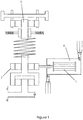
- An exemplary known embodiment of an energy recovery device will now be described with reference to
Figure 1 which provides an energy recovery device employing a SMA engine indicated byreference numeral 1. TheSMA engine 1 comprises an SMA actuation core. The SMA actuation core is comprised of SMA material clamped or otherwise secured at a first point which is fixed. At the opposing end, the SMA material is clamped or otherwise secured to adrive mechanism 2. Thus whilst the first point is anchored the second point is free to move albeit pulling thedrive mechanism 3. Animmersion chamber 4 adapted for housing the SMA engine and is adapted to be sequentially filled with fluid to allow heating and/or cooling of the SMA engine. Accordingly, as heat is applied to the SMA core it is free to contract. Suitably, the SMA core comprises a plurality of parallel wires, ribbons or sheets of SMA material. Typically, a deflection in and around 4% is common for such a core. Accordingly, when a 1 m length of SMA material is employed, one might expect a linear movement of approximately 4 cm to be available. Higher movements can also be obtained. It will be appreciated that the force that is provided depends on the mass of wire used. Such an energy recovery device is described inPCT Patent Publication number WO2013/087490 , assigned to the assignee of the present invention, and is incorporated fully herein by reference. - For such an application, the contraction of such material on exposure to a heat source is captured and converted to usable mechanical work. A useful material for the working element of such an engine has been proven to be Nickel-Titanium alloy (NiTi). This alloy is a well-known Shape-Memory Alloy and has numerous uses across different industries.
- Force is generated through the contraction and expansion of this alloy (presented as a plurality of wires) within the working core, via a piston and transmission mechanism. The most important aspect of this system is the ability to secure the NiTi elements at both ends such that a reliable assembly is created, enabling high-force, low displacement work to be performed for a maximum number of working cycles. Accordingly, depending on the requirements of a particular configuration and the mass of SMA material needed a plurality of wires may be employed together in a single core.
- The wire's extremities have to be presented in such a way that they are able to be securely fixed in a metallic support, hereinafter referred to as a bundle holder.
- Thus far, a useful material for such a working mass has been found to be Nickel-Titanium alloy (NiTi). This alloy is a well-known Shape Memory Alloy and has numerous uses across different industries.
- The NiTi wires form the working element of the engine. Force is generated through the contraction and expansion of these elements within the working core, via a piston and a mechanical/hydraulic transmission system. In one embodiment a piston and crank mechanism could be used. An important aspect of this system is the ability to secure the NiTi elements at both ends such that a strong and reliable union is created, enabling high-force, low displacement work to be performed for a maximum number of working cycles.
- In order to secure the NiTi wires in the engine, it is required to develop a system that can anchor each wire at both ends, in such a fashion as will allow it to operate under high load. This system has been designated as the "bundle holder". The bundle holder must overcome two specific problems:
- 1) Transmit the high-force, low displacement load of the NiTi wires during operation. This is a single degree of freedom (DOF) system whereby one end of the bundle is secured and remains stationary, whilst the opposing end is free to move in one axis of displacement to enable the movement of the piston and the harnessing of the work.
- 2) Enable the close-packing of the wires, insofar as possible, to enable maximum heat transfer from the transiting water to the wire and vice versa.
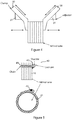
- In one solution
Figure 2 illustrates a friction fit method to ensure the close packing of the working wires, according to a first aspect of the invention. Thewires 10 are grouped together and clamped using abracket mechanism 20. The bracket may be constructed from metal or otherwise and is compressed around the wire bundle in such a way as to allow any force exerted on or by the wires to be transmitted through the bracket by way of a frictional or interference fit. In essence, this bracket keeps the wires closely packed whilst also enabling the transmission of force through the friction fit of the bracket and the wires. Close-packing of the wires in this manner provides advantages for minimizing the total size of the system and for ensuring compact realisation of the energy recovery device. - The embodiment enables the fixing of the SMA or NiTi wires in such a way that the high force developed by their contraction can be safely transmitted such that mechanical work can be produced.
- As is generally understood, a Shape-Memory Alloy (SMA) or Negative Thermal Expansion (NTE) material will contract not only longitudinally (along a central axis) but also laterally (in the diametrical plane). It is foreseeable, therefore, that any bundle of working elements comprised of such material would likely encounter shrinkage in the lateral direction. This shrinkage can have negative implications for the integrity of a friction-based fixing system, as the loss of the cross sectional area of the bundle, however small, would enable a relaxation of the frictional bond, thus enabling slippage or total loss of adhesion.
- One embodiment that avoids this is illustrated in
Figure 3 . Swages or flares are added to the terminal ends of thewires 10. Asimple swage system 11 creates a mechanical barrier to the slippage of the wire element through a designated guide hole in the bundle holder. In such a set-up, each wire has its own individual guide hole, giving rise to a "salt shaker" type bundle holder system whereby a solid plate of material is pierced many times (however many wires are required in the given engine) to enable a given number of wires to be utilised in the engine. In this arrangement, the swage provides a mechanical barrier itself, with the force of the contraction transmitted directly through the interface of the swage and the bundle holder. - By swaging or flaring the ends of the
NiTi wire 11, and by grouping them according to the principle laid out in the previous concept, a cumulative flared effect may be obtained at the terminal end of the wires. Once the flared terminals are secured in place (Fig. 3c ), the flaring of individual wires in this way prevents the slippage that may occur by the lateral shrinkage of the material by presenting an obstacle to the transit of adjacent wires through the holder itself. In essence, an aggregate flare is created, which resists the slippage of any individual wire and in so doing, preserves the integrity of the bundle as a whole. - This embodiment enables the NiTi wires to be fixed in such a way that the high force developed by their contraction can be safely transmitted such that mechanical work can be produced.
- A useful material for the working element of such an engine has been proven to be Nickel-Titanium alloy (NiTi). This alloy is a well-known Shape Memory Alloy and has numerous uses across different industries.
- As described above force is generated through the contraction and expansion of this alloy (presented as a plurality of wires) within the working core, via a piston and transmission mechanism. The most important aspect of this system is the ability to secure the NiTi elements at both ends such that a reliable assembly is created, enabling high-force, low displacement work to be performed for a maximum number of working cycles.
- In order for a Nitinol core to actuate a piston a method must be identified for fixing a bundle of wires so that one end is fixed to the top of the core and the other end is attached to the piston.
- A friction fit is one possible way of securing wires together. Basically a friction fit is where the roughness of two surfaces is used to prevent slippage or movement of an object. The effectiveness of the fit is determined by the coefficient of friction for each surface, the area of contact and the pressure between the surfaces.
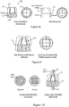
-
Figure 4 shows a method of securing a bundle of wires by means of friction fitting. The friction fit is created by a device which works in a similar manner to a pillar drill chuck. However a standard chuck is designed only to holder one piece of material. - As can be seen in
Figure 4 the chuck comprises two components: aclamp 30 and anadjuster 31. The adjuster is made of one single circular piece while the clamp can consist of several units in order to increase surface contact with the wire bundle. The adjuster is connected to the clamp by an angled threaded section. When the adjuster is rotated in a clockwise manner it causes the angled section of the clamp to move down. The clamp also has a vertically flat section which is parallel with the bundle of wire. As the angled section moves down it causes the flat section to move horizontally which applies a force on the outer surface of the bundle. The result is that the individual wires are pushed together increasing the friction between them and with enough applied force, preventing individual wires from being pulled from the bundle. - The main advantage of this embodiment is that the chuck allows for the force applied on the bundle to be manually adjusted by means of a tool such as a chuck key.
- The chuck can be made of materials which have high corrosion resistance in water such as stainless steel or aluminium. Greasing the threads on the clamp and adjuster can also combat against the unit seizing up.
- The motivation behind the creation of this embodiment was to be able to fix the wires in such a way that the high force developed by their contraction can be safely transmitted such that mechanical work can be produced.
- As mentioned previously, a useful material for the working element of such an engine has been proven to be Nickel-Titanium alloy (NiTi). This alloy is a well-known Shape Memory Alloy and has numerous uses across different industries.
- Force is generated through the contraction and expansion of this alloy (presented as a plurality of wires) within the working core, via a piston and transmission mechanism. The most important aspect of this system is the ability to secure the NiTi elements at both ends such that a reliable assembly is created, enabling high-force, low displacement work to be performed for a maximum number of working cycles.
- In order for a Nitinol core to actuate a piston a method must be identified for fixing a bundle of wires so that one end is fixed to the top of the core and the other end is attached to the piston.
- A friction fit is one possible way of securing wires together. Basically a friction fit is where the roughness of two surfaces is used to prevent slippage or movement of an object. The effectiveness of the fit is determined by the coefficient of friction for each surface, the area of contact and the pressure between the surfaces.
-
Figure 5 show aconcept 40 for creating a friction fit between a bundle of wires with the purpose of preventing any wire from being removed during service due to a vertical force. As can be seen achain 41 is provided which is made from a steel or other material. Connected to the chain is ashackle 42 of a size allowing the chain to be fully passed through. - This embodiment allows a friction fit to be created by wrapping the chain around the bundle and then passing it though a shackle. The chain passed through the shackle is tensioned so as to force the wires together and therefore increase the friction between them. When the chain is fully tensioned a locking pin is placed through the bore of the chain which is closest to the shackle. This prevents the chain from pulling through the shackle therefore maintaining the tension in the chain.
- This embodiment reduces the steps required in manufacturing a bundle as the wire simply has to be cut. Also this method allows for the bundle of wires to be opened quickly by removing the pin which would reduce the time required to remove or insert wires during service.
- The motivation behind the creation of this concept was to be able to fix the NiTi wires in such a way that the high force developed by their contraction can be safely transmitted such that mechanical work can be produced.
- In order for a Nitinol core to actuate a piston a method must be identified for fixing a bundle of wires so that one end is fixed to the top of the core and the other end is attached to the piston.
- A friction fit is one possible way of securing wires together. Basically a friction fit is where the roughness of two surfaces is used to prevent slippage or movement of an object. The effectiveness of the fit is determined by the coefficient of friction for each surface, the area of contact and the pressure between the surfaces.
-
Figure 6 illustrates a method of creating a friction fit for the purpose of holding two or more solid/ hollow wires together. As can be seen the use of aspring clip 50 can be adapted to grip and hold the ends of the wires together in a tight fit arrangement. - A
spring clip 50 is typically a continuous piece of stiff elastic material that is wrapped in a circular fashion and fitted back through a slot. Each end consists of a vertical adjusting point. When these points are pulled together it causes the diameter of the clip to increase. In order to create a friction fit between the bundles of wires, the bundle would be packed into the clip when it has been extended to the larger diameter. When in position, the adjustment points are released which causes the diameter to decrease. The decrease in diameter causes the clip to force the wires together and therefore increase the friction between each wire. The force applied to the wire bundle is determined by the elastic stiffness of the material used in the clip. If the force is high enough this will prevent individual wires from pulling out during operation. - Also the advantage with this method is that as the wire diameter decrease when phase transformation occur, the clip will also decrease its inner radius and therefore maintain a force to holder the bundle together.
- The motivation behind the creation of this embodiment was to be able to fix the wires in such a way that the high force developed by their contraction can be safely transmitted such that mechanical work can be produced.
- In order for a core to actuate a piston a method needs to be identified for fixing a bundle of wires so that one end is fixed to the top of the core and the other end is attached to the piston.
- A friction fit is one possible way of securing wires together. Basically a friction fit is where the roughness of two surfaces is used to prevent slippage or movement of an object. The effectiveness of the fit is determined by the coefficient of friction for each surface, the area of contact and the pressure between the surfaces.
-
Figure 7 shows another embodiment for creating a friction fit. This embodiment is based on the previously discussed chuck concept. This concept creates a friction fit by using at least oneclamp 60 to press in against the outer surface of the wire bundle, similar to the chuck concept. However with the chuck concept the clamps are manually adjusted which creates a potential risk of the chuck becoming loose during service or accidentally being left loose during maintenance. - This embodiment avoids this problem by using
springs 62 to force the clamps against the surface therefore increasing the friction between the wires. InFigure 7 a top view is also illustrated where three clamps are used to contact the bundle. During installation, theclamps 60 are pulled back and held. The bundle is then inserted to the core. Once in position the clamps are released where they enclose the outside of the bundle. The force applied is dependent on the stiffness of the springs used. - This embodiment provides a solution to an issue involved in securing Shape Memory Alloy (SMA) wire in way which does not require the individual positioning of the wires during bundle assembly. Current methods employed involved the use of "salt shaker" embodiments, which consisted of a metal plate with an individual hole drilled for each wire contained in a bundle. This method entails lengthy manual assembly times which cause large lead times and costs during assembly. The embodiment discussed herein describe a method of securing bundles of wires whereby the order in which the wires are installed can be random, thereby allowing more autonomous and faster assembly of the SMA wire bundles.
- This embodiment also provides a method of bundle securement which can eliminate the need for swaged or domed wires, whereby the friction forces applied on the wire is enough to secure it. This would be advantageous against the salt shaker concept as it would remove a step of SMA wire processing thereby reducing manufacturing costs.
- This embodiment involves the use of a
cable gland 70 for securing the wire bundles together. Cable glands are typically used to secure electrical wire into a container in order to prevent external environments affecting the internal electrical components. This embodiment proposes an alternate use for this device. The cable gland component is illustrated inFigure 8 , and consists of two pieces: thebase 71 andcap 72. - The base 71 component consists of flexible fins 73 or teeth and a threaded feature 74. The
cap 72 can be seen to contain a matching female tread to the base, as well as a tapered internal geometry. When rotated onto the base, the lowering cap causes the fins to be forced radially towards each other. These closing teeth, which may have a lining to increase friction, are used to secure wire which runs through the hollow centre. This operation is illustrated inFigure 9 . - The application proposed in using this component for securing the wire bundle may require a more robust version of the device, for example one manufactured from steel.
Figure 10 shows the device in this application of securing wire bundles together. - Force is generated through the contraction and expansion of this alloy (presented as a plurality of wires) within the working core, via a piston and transmission mechanism. The most important aspect of this system is the ability to secure the wire elements at both ends such that a reliable assembly is created, enabling high-force, low displacement work to be performed for a maximum number of working cycles.
- The embodiment provides a solution to an issue involved in securing Shape Memory Alloy (SMA) wire in a way which does not require the individual positioning of the wires during bundle assembly. Current methods employed involved the use of "salt shaker" embodiments, which consists of a metal plate with an individual hole drilled for each wire contained in a bundle. This method entails lengthy manual assembly times which cause large lead times and costs during assembly. This embodiment provides a method of securing bundles of wires whereby the order in which the wires are installed can be random, thereby allowing more autonomous and faster assembly of the SMA wire bundles.
- This embodiment also provides a method of bundle securement which may eliminate the need for swaged or domed wires, whereby the friction forces applied on the wire are enough to secure it. This is advantageous as it removes a step of SMA wire processing thereby reducing manufacturing costs.
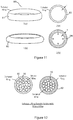
- This embodiment involves the use of pressurised air or fluid and an elastic
tubular ring 80 in order to secure wire bundles together 10. When deflated, this ring will have a greater inner diameter than the ring when it is fully inflated. This property can secure the wires by placing the wires tightly within the ring pre-inflation. At this point, inflation of the ring will cause a radial pressure to be applied to the wires contained within its centre, resulting in them being secured in place by friction.Fig 11 illustrates the operation of this embodiment. - As can be seen in
Fig 11 above, 81 shows the ring in its deflated state and 82 shows the ring in its inflated state. The ring is shown to be taller and thinner initially. However, with the introduction of pressure, the ring decreases in height as well as increasing its width and tubular thickness. This is primarily illustrated inplan view Fig 12 showing a plan view of the wires secured by the substantiallytubular ring - The material with which the ring is manufactured should be resilient enough to withstand the force required to secure the wire, while being elastic enough to provide the desired displacement needed to increase its inner diameter. One material could be nylon, which can provide these attributes, similar to attributes in the application of angioplasty (heart) balloons used in key-hole surgeries. It can also be advantageous to construct a container for this ring, which would restrict its outer diameter expansion, further providing more force/displacement to its inner expansion. The container can also be useful when loading the wire bundles pre inflation as it provides a solid guide as opposed to the relatively flexible inflatable ring. This is shown in
Figure 13 and 14 , where the embodiment is shown with and without the wire bundle respectively. - Force is generated through the contraction and expansion of this alloy (presented as a plurality of wires) within the working core, via a piston and transmission mechanism. The most important aspect of this system is the ability to secure the wire elements at both ends such that a reliable assembly is created, enabling high-force, low displacement work to be performed for a maximum number of working cycles.
- This embodiment provides a method of bundle securement which can obviate the need for swaged or domed wires, whereby the friction forces applied on the wire is enough to secure it. This is advantageous as it removes a step of SMA wire processing thereby reducing manufacturing costs, in addition to being constructed of non-complicated parts.
- A method of securing a bundle of wires can be realised through the use of
straight brackets 90, screws, and nuts. The brackets would be used to provide a force on thewires 10 through the tightening of the screw. These brackets can also have a secondary function as spacers.Figure 15 illustrates a number of views of such an embodiment where top (a) and side (b) & (c) views are shown. - The brackets act as clamps, increasing the force exerted onto the Nitinol wires as the screw is turned and tightened. The embodiment is advantageous as it allows a large number of wires to be secured at once and does not require complicated parts. The surface of the bracket which comes in contact with the SMA wire may also be roughened in order to increase the frictional force applied and hence further secure the wires. After securing the wires using this method, the bundle may be held in place within a core using a
holder slot 100, as shown inFig 16 . - Force is generated through the contraction and expansion of this alloy (presented as a plurality of wires) within the working core, via a piston and transmission mechanism. The most important aspect of this system is the ability to secure the wire elements at both ends such that a reliable assembly is created, enabling high-force, low displacement work to be performed for a maximum number of working cycles.
- In order to secure the plurality of wires in a reliable and durable fashion a system/device capable of anchoring them at both ends has to be developed. This system has to operate under high load. This assembly can be designated as a "bundle holder".
- The bundle holder must overcome some specific problems:
- 1) Transmit the high-force, low displacement load of the wires during operation.
- 2) Enable the close-packing of the wires, insofar as possible, to enable maximum heat transfer from the transiting water to the wire and vice versa.
- 3) From a manufacturing point of view, it has to eliminate the tedious and strenuous process of placing hundreds of wires in some sort of support and reduce production time and costs.
- The following is a method to grip groups of wires in a bundle under loading conditions without the need to manufacture complex parts that can also be used on wires that have been domed or swaged on both ends.
- A
metal ring 110 can be placed around a group of wires and a press then used to compress the ring around the wires which would then form a tight and compact bundle. This arrangement does not allow one wire to pass by another because of thedomes 111 orswages 111 being slightly wider than the rest of the wire, as shown inFigure 17 and18 . - The compression ring acts to retain the wires in position, and maintains a gap between the wires that is smaller than the diameter of the swage or dome at any stage. This prevents pull through. The compound effect under loading is the radial transmission of the applied load onto the compression ring which can be designed to sit on a frame.
- Furthermore, to hold wires in position prior to compression of the ring, a polymer, rubber or ceramic based liquid capable of setting to a solid form can be initially applied to the wires. When set, the wires are held in place. The compression ring is then applied to the outside of the newly set solid and compressed, as shown in
Figure 18 . The polymer/rubber/ceramic material is non-load bearing, and the load is again transferred radially onto the compression ring. - In order to secure the plurality of wires in a reliable and durable fashion a system/device capable of anchoring them at both ends has to be developed. This system has to operate under high load. This assembly has been designated as the "bundle holder"
- The bundle holder must overcome some specific problems:
- 1) Transmit the high-force, low displacement load of the wires during operation.
- 2) Enable the close-packing of the wires, insofar as possible, to enable maximum heat transfer from the transiting water to the wire and vice versa.
- 3) From a manufacturing point of view, it has to eliminate the tedious and strenuous process of placing hundreds of these wires in some sort of support and reduce production time and costs.
- For this bundle holder embodiment the wires can be mounted on support parts that have a number of
grooves 120. The grooves have a double role: - 1. To increase the surface on which the wire is in contact with the support, so that the friction won't allow the wires to move.
- 2. A role of guiding the wires so they will not be on top of each other (even tensioning when wires are gripped and splitting of the paths of the wires)
-
Figure 19 is a schematic of thegrooved support 120 for the SMA wires and of the clamps (a) in the open position and (b) in the closed position. The clamps can have additional elastic tensioners on the inside to ensure that the wires will not get loose with time. - The bottom part of the support is wide so it can split the wires and improve the heat transfer. The support can be mounted in a plate used as a bundle holder.
- This embodiment solves the problem of swaging wires individually and it would use a tightening element with elastic tensioning elements to fix them into place.
- This bundle holder design is solving many of the inherited problems of fixing together the wires, while keeping its structural integrity intact.
The bundle holder consists of a plurality of threaded wires fixed together and placed tightly into a tapered hole and split collet arrangement. The treads act to maintain a good contact in between the wires and not allow them to slip from the bundle while cycling. -
Fig. 20 presents types ofthreads 130 for the SMA wire 10: a) straighthelical thread 131; b) taperedhelical thread 132.Fig. 21 illustrates a plurality of threadedSMA wires 140 in a bundle. When a force is applied to the wires in the bundle, the split collet and taper compact the threads together.Fig. 22 illustrates the SMA wires in a tapered collet, illustrated by thereference numeral 150. - The diameter of the thread is selected so that the thinnest part of the structure would be the engaged part of the wire (the section immersed in cold/hot fluid) that is immediately below the thread.
- The length of wire interacting with the fluid flow is drawn or rolled to a smaller diameter, hence a gap between the wires is introduced to facilitate fluid flow.
- The reduced diameter can be optimised to allow for the optimum heat transfer between the fluid and SMA wires.
-
Figure 23a & 23b illustrates a number of threaded wire designs according to anotherembodiment 160. The ends of thewire 161 are threaded and butted in order for them to be implemented in a compression bundle fitting, as illustrated inFigure 23a . In one embodiment a thread is formed along thefull length 162 of the wire, as shown inFigure 23b . The thread increases the surface area of the wire, as well as increase turbulence along this surface during cyclic heating and cooling via a working fluid. This increased surface area and turbulence will serve to increase the thermodynamic performance of the wires. - It is desirable to minimise friction losses due to the added complexity of the flow path. A method of reducing this effect can be to optimise wire layout within the wire bundle whereby the outer wires of the bundle would be smooth (where the working fluid can transfer heat easily), and the inner wires would have the threaded lengths as they would be hardest to reach during heat transfer to the entire bundle. A step further to this is to have a gradual increase in the sizing of the threads, where the outer wires begin smooth but gradually have deeper threads as the wires progress to the centre.
-
Figure 24 illustrates an embodiment of a core with a plurality ofSMA wires 10 arranged in parallel in use in an energy recovery device. The core is housed in a chamber and is connected to a fluid source viavalves 170 andmanifolds 171, 172. TheSMA wires 10 are secured at both ends by a bottom andtop bundle holder 172 and 173. One end of the core is in communication with apiston 174 that is moveable in response to expansion and contraction of the SMA wires to generate energy.
In the specification the terms "comprise, comprises, comprised and comprising" or any variation thereof and the terms include, includes, included and including" or any variation thereof are considered to be totally interchangeable and they should all be afforded the widest possible interpretation and vice versa.
Claims (16)
- An energy recovery device comprising:a drive mechanism (2);an engine (1) comprising a plurality of Shape Memory Alloy (SMA) elements or Negative Thermal Expansion (NTE) elements fixed at a first end and connected at a second end to the drive mechanism characterised in that the engine defines a core with a plurality of NTE or SMA elements (10) arranged in parallel wherein a bracket (20) is adapted to clamp the SMA or NTE elements together at one end such that the SMA or NTE elements (10) are arranged in a bundle friction fit configuration to ensure the SMA or NTE elements (10) are tightly packed together.
- The energy recovery device of claim 1 wherein at least one SMA or NTE element (10) is swaged (11) at one end to create a mechanical barrier to prevent slippage of the element in use.
- The energy recovery device of any preceding claim comprising a friction fit device.
- The energy recovery device of claim 3 wherein the device comprises a chuck (30, 31) adapted to secure the SMA or NTE elements (10) in a friction fit configuration.
- The energy recovery device of claim 4 wherein the chuck comprises a clamp (30) and an adjuster (31) configured to adjust the force applied to the SMA or NTE elements.
- The energy recovery device of any preceding claim comprising a friction fit device (40) wherein the device comprises a chain (41) adapted to be tensioned around the SMA or NTE elements using a shackle (42).
- The energy recovery device of any preceding claim comprising a friction fit device wherein the device comprises a spring clip (50) to ensure the SMA or NTE elements (10) are tightly packed together.
- The energy recovery device of claim 7 wherein the spring clip (50) comprises a stiff material wrapped in a circular fashion and fitted back through a slot.
- The energy recovery device of any preceding claim comprising a friction fit device wherein the device comprises a clamp (60) adapted to secure the SMA or NTE elements (10) in a friction fit configuration wherein the clamp (60) is biased by at least one spring (62) to force the clamp around the SMA or NTE elements.
- The energy recovery device of any preceding claim comprising a friction fit device wherein the device comprises a cable gland (70) to secure the SMA or NTE elements (10) in a friction fit configuration.
- The energy recovery device of any preceding claim comprising a friction fit device wherein the device comprises a pressurised elastic tubular ring (80) to secure the SMA or NTE elements (10) in a friction fit configuration.
- The energy recovery device of claim 11 wherein the elastic tubular ring (80) is inflatable.
- The energy recovery device of any preceding claim comprising a friction fit device wherein the device comprises a compression ring (110) configured to retain the SMA or NTE elements in position.
- The energy recovery device of any preceding claim comprising a friction fit device wherein the device comprises at least one groove support (120).
- The energy recovery device of any preceding claim wherein at least one SMA or NTE element (10) comprises a threaded wire (130).
- The energy recovery device of claim 15 wherein the threaded wire comprises a straight helical thread (131) or a tapered helical thread (132).
Applications Claiming Priority (2)
| Application Number | Priority Date | Filing Date | Title |
|---|---|---|---|
| GB1422153.5A GB2533159A (en) | 2014-12-12 | 2014-12-12 | Wire element arrangement in an energy recovery device |
| PCT/EP2015/079660 WO2016092118A1 (en) | 2014-12-12 | 2015-12-14 | Wire element arrangement in an energy recovery device |
Publications (2)
| Publication Number | Publication Date |
|---|---|
| EP3230585A1 EP3230585A1 (en) | 2017-10-18 |
| EP3230585B1 true EP3230585B1 (en) | 2019-03-27 |
Family
ID=55315372
Family Applications (1)
| Application Number | Title | Priority Date | Filing Date |
|---|---|---|---|
| EP15832797.3A Active EP3230585B1 (en) | 2014-12-12 | 2015-12-14 | Wire element arrangement in an energy recovery device |
Country Status (11)
| Country | Link |
|---|---|
| US (1) | US10036118B2 (en) |
| EP (1) | EP3230585B1 (en) |
| JP (1) | JP6636536B2 (en) |
| KR (1) | KR20170107989A (en) |
| CN (1) | CN107250535A (en) |
| AU (1) | AU2015359298B2 (en) |
| BR (1) | BR112017012311A2 (en) |
| CA (1) | CA2970573A1 (en) |
| GB (1) | GB2533159A (en) |
| IL (1) | IL252822A0 (en) |
| WO (1) | WO2016092118A1 (en) |
Families Citing this family (9)
| Publication number | Priority date | Publication date | Assignee | Title |
|---|---|---|---|---|
| US20120260590A1 (en) | 2011-04-12 | 2012-10-18 | Lambert Walter L | Parallel Wire Cable |
| US8474219B2 (en) | 2011-07-13 | 2013-07-02 | Ultimate Strength Cable, LLC | Stay cable for structures |
| GB201511487D0 (en) * | 2015-06-30 | 2015-08-12 | Exergyn Ltd | Method and system for efficiency increase in an energy recovery device |
| DE102017106220B3 (en) * | 2017-03-22 | 2018-09-06 | Component Engineering Services Gmbh | actuator |
| JP7063581B2 (en) * | 2017-11-14 | 2022-05-09 | フォスター電機株式会社 | Actuator |
| CN109356017B (en) * | 2018-10-30 | 2023-06-27 | 南昌大学 | Concrete continuous box girder bridge with self-recovery limiting and prestress loss reducing combined structure |
| GB201820901D0 (en) | 2018-12-20 | 2019-02-06 | Exergyn Ltd | Improvements to wire forming of shape-memory alloys (SMAs) or negative thermal expansion (NTE) materials for use in an energy recovery system |
| KR102222056B1 (en) * | 2019-06-20 | 2021-03-03 | 엠케이프리시젼 주식회사 | Bypass with tube inserted and method of making the same |
| DE102021127368A1 (en) | 2021-10-21 | 2023-04-27 | Universität des Saarlandes, Körperschaft des öffentlichen Rechts | Method for producing a wire bundle actuator element from thermoelastic actuator wire sections and wire bundle actuator element |
Family Cites Families (10)
| Publication number | Priority date | Publication date | Assignee | Title |
|---|---|---|---|---|
| US4306415A (en) * | 1978-06-09 | 1981-12-22 | Hochstein Peter A | Thermal energy scavenger (flow control) |
| US4231223A (en) * | 1978-06-09 | 1980-11-04 | Pringle William L | Thermal energy scavenger (rotating wire modules) |
| JPH05306676A (en) * | 1992-04-30 | 1993-11-19 | Central Res Inst Of Electric Power Ind | Solid phase thermal energy generating system |
| KR20010087231A (en) * | 2000-03-03 | 2001-09-15 | 레비스 스테픈 이 | Shape memory alloy bundles and actuators |
| US7340883B2 (en) * | 2004-11-12 | 2008-03-11 | The Boeing Company | Morphing structure |
| US8881521B2 (en) * | 2008-03-07 | 2014-11-11 | GM Global Technology Operations LLC | Cable protection system and method of reducing an initial stress on a cable |
| WO2009114357A2 (en) | 2008-03-07 | 2009-09-17 | Gm Global Technology Operations, Inc. | Shape memory alloy cables |
| CN102650274B (en) * | 2011-02-28 | 2015-07-15 | 通用汽车环球科技运作有限责任公司 | Shape memory alloy heat engine and energy collecting system |
| GB2497542A (en) * | 2011-12-13 | 2013-06-19 | Dublin Inst Of Technology | Shape memory alloy motor with spring energy accumulator |
| US9021801B2 (en) * | 2012-08-31 | 2015-05-05 | GM Global Technology Operations LLC | Compensating for incomplete reversal in mechanisms incorporating shape memory alloy wire |
-
2014
- 2014-12-12 GB GB1422153.5A patent/GB2533159A/en not_active Withdrawn
-
2015
- 2015-12-14 CN CN201580075998.4A patent/CN107250535A/en active Pending
- 2015-12-14 KR KR1020177019406A patent/KR20170107989A/en unknown
- 2015-12-14 CA CA2970573A patent/CA2970573A1/en not_active Abandoned
- 2015-12-14 WO PCT/EP2015/079660 patent/WO2016092118A1/en active Application Filing
- 2015-12-14 JP JP2017549598A patent/JP6636536B2/en active Active
- 2015-12-14 AU AU2015359298A patent/AU2015359298B2/en not_active Ceased
- 2015-12-14 EP EP15832797.3A patent/EP3230585B1/en active Active
- 2015-12-14 BR BR112017012311A patent/BR112017012311A2/en not_active Application Discontinuation
- 2015-12-14 US US15/535,153 patent/US10036118B2/en active Active
-
2017
- 2017-06-11 IL IL252822A patent/IL252822A0/en unknown
Non-Patent Citations (1)
| Title |
|---|
| None * |
Also Published As
| Publication number | Publication date |
|---|---|
| JP6636536B2 (en) | 2020-01-29 |
| AU2015359298A1 (en) | 2017-07-13 |
| GB2533159A (en) | 2016-06-15 |
| EP3230585A1 (en) | 2017-10-18 |
| KR20170107989A (en) | 2017-09-26 |
| JP2018507354A (en) | 2018-03-15 |
| WO2016092118A1 (en) | 2016-06-16 |
| CN107250535A (en) | 2017-10-13 |
| US10036118B2 (en) | 2018-07-31 |
| CA2970573A1 (en) | 2016-06-16 |
| IL252822A0 (en) | 2017-08-31 |
| AU2015359298B2 (en) | 2019-02-07 |
| US20170362772A1 (en) | 2017-12-21 |
| BR112017012311A2 (en) | 2018-05-02 |
Similar Documents
| Publication | Publication Date | Title |
|---|---|---|
| EP3230585B1 (en) | Wire element arrangement in an energy recovery device | |
| US20140086772A1 (en) | Actuator element and an actuator for generating a force and/or a movement | |
| EP1520984A2 (en) | Shape memory alloy bundles and actuators | |
| NO20130016A1 (en) | Form memory alloy driven hydraulic accumulator with start plates | |
| EP3149327B1 (en) | Bundle holder for use in an energy recovery device | |
| JP2018507354A5 (en) | ||
| EP3234354B1 (en) | Heat transfer in an energy recovery device | |
| US10563640B2 (en) | Optimised diametric contraction of a SMA element for use in an energy recovery device | |
| US20100092238A1 (en) | Active material elements having reinforced structural connectors | |
| WO2016092120A1 (en) | Protective element for use in an energy recovery device | |
| EP2460637A1 (en) | Method of manufacturing a push rod of a vacuum interrupter | |
| US20200190645A1 (en) | Wire forming of Shape-Memory Alloys (SMAs) or Negative Thermal Expansion (NTE) materials for use in an Energy Recovery System | |
| WO2018002183A1 (en) | Method and system for dynamic balancing of a core in an energy recovery device | |
| US11781532B2 (en) | SMA material performance boost for use in an energy recovery device | |
| WO2018229240A1 (en) | Sma material performance boost for use in an energy recovery device |
Legal Events
| Date | Code | Title | Description |
|---|---|---|---|
| STAA | Information on the status of an ep patent application or granted ep patent |
Free format text: STATUS: THE INTERNATIONAL PUBLICATION HAS BEEN MADE |
|
| PUAI | Public reference made under article 153(3) epc to a published international application that has entered the european phase |
Free format text: ORIGINAL CODE: 0009012 |
|
| STAA | Information on the status of an ep patent application or granted ep patent |
Free format text: STATUS: REQUEST FOR EXAMINATION WAS MADE |
|
| STAA | Information on the status of an ep patent application or granted ep patent |
Free format text: STATUS: EXAMINATION IS IN PROGRESS |
|
| 17P | Request for examination filed |
Effective date: 20170711 |
|
| AK | Designated contracting states |
Kind code of ref document: A1 Designated state(s): AL AT BE BG CH CY CZ DE DK EE ES FI FR GB GR HR HU IE IS IT LI LT LU LV MC MK MT NL NO PL PT RO RS SE SI SK SM TR |
|
| AX | Request for extension of the european patent |
Extension state: BA ME |
|
| 17Q | First examination report despatched |
Effective date: 20171017 |
|
| GRAP | Despatch of communication of intention to grant a patent |
Free format text: ORIGINAL CODE: EPIDOSNIGR1 |
|
| STAA | Information on the status of an ep patent application or granted ep patent |
Free format text: STATUS: GRANT OF PATENT IS INTENDED |
|
| DAV | Request for validation of the european patent (deleted) | ||
| DAX | Request for extension of the european patent (deleted) | ||
| INTG | Intention to grant announced |
Effective date: 20180309 |
|
| GRAJ | Information related to disapproval of communication of intention to grant by the applicant or resumption of examination proceedings by the epo deleted |
Free format text: ORIGINAL CODE: EPIDOSDIGR1 |
|
| STAA | Information on the status of an ep patent application or granted ep patent |
Free format text: STATUS: EXAMINATION IS IN PROGRESS |
|
| INTC | Intention to grant announced (deleted) | ||
| GRAS | Grant fee paid |
Free format text: ORIGINAL CODE: EPIDOSNIGR3 |
|
| STAA | Information on the status of an ep patent application or granted ep patent |
Free format text: STATUS: GRANT OF PATENT IS INTENDED |
|
| GRAP | Despatch of communication of intention to grant a patent |
Free format text: ORIGINAL CODE: EPIDOSNIGR1 |
|
| INTG | Intention to grant announced |
Effective date: 20181012 |
|
| GRAA | (expected) grant |
Free format text: ORIGINAL CODE: 0009210 |
|
| STAA | Information on the status of an ep patent application or granted ep patent |
Free format text: STATUS: THE PATENT HAS BEEN GRANTED |
|
| AK | Designated contracting states |
Kind code of ref document: B1 Designated state(s): AL AT BE BG CH CY CZ DE DK EE ES FI FR GB GR HR HU IE IS IT LI LT LU LV MC MK MT NL NO PL PT RO RS SE SI SK SM TR |
|
| REG | Reference to a national code |
Ref country code: GB Ref legal event code: FG4D |
|
| REG | Reference to a national code |
Ref country code: CH Ref legal event code: EP |
|
| REG | Reference to a national code |
Ref country code: AT Ref legal event code: REF Ref document number: 1113404 Country of ref document: AT Kind code of ref document: T Effective date: 20190415 |
|
| REG | Reference to a national code |
Ref country code: IE Ref legal event code: FG4D |
|
| REG | Reference to a national code |
Ref country code: DE Ref legal event code: R096 Ref document number: 602015027343 Country of ref document: DE |
|
| PG25 | Lapsed in a contracting state [announced via postgrant information from national office to epo] |
Ref country code: NO Free format text: LAPSE BECAUSE OF FAILURE TO SUBMIT A TRANSLATION OF THE DESCRIPTION OR TO PAY THE FEE WITHIN THE PRESCRIBED TIME-LIMIT Effective date: 20190627 Ref country code: FI Free format text: LAPSE BECAUSE OF FAILURE TO SUBMIT A TRANSLATION OF THE DESCRIPTION OR TO PAY THE FEE WITHIN THE PRESCRIBED TIME-LIMIT Effective date: 20190327 Ref country code: LT Free format text: LAPSE BECAUSE OF FAILURE TO SUBMIT A TRANSLATION OF THE DESCRIPTION OR TO PAY THE FEE WITHIN THE PRESCRIBED TIME-LIMIT Effective date: 20190327 Ref country code: SE Free format text: LAPSE BECAUSE OF FAILURE TO SUBMIT A TRANSLATION OF THE DESCRIPTION OR TO PAY THE FEE WITHIN THE PRESCRIBED TIME-LIMIT Effective date: 20190327 |
|
| REG | Reference to a national code |
Ref country code: NL Ref legal event code: MP Effective date: 20190327 |
|
| PG25 | Lapsed in a contracting state [announced via postgrant information from national office to epo] |
Ref country code: NL Free format text: LAPSE BECAUSE OF FAILURE TO SUBMIT A TRANSLATION OF THE DESCRIPTION OR TO PAY THE FEE WITHIN THE PRESCRIBED TIME-LIMIT Effective date: 20190327 Ref country code: BG Free format text: LAPSE BECAUSE OF FAILURE TO SUBMIT A TRANSLATION OF THE DESCRIPTION OR TO PAY THE FEE WITHIN THE PRESCRIBED TIME-LIMIT Effective date: 20190627 Ref country code: GR Free format text: LAPSE BECAUSE OF FAILURE TO SUBMIT A TRANSLATION OF THE DESCRIPTION OR TO PAY THE FEE WITHIN THE PRESCRIBED TIME-LIMIT Effective date: 20190628 Ref country code: HR Free format text: LAPSE BECAUSE OF FAILURE TO SUBMIT A TRANSLATION OF THE DESCRIPTION OR TO PAY THE FEE WITHIN THE PRESCRIBED TIME-LIMIT Effective date: 20190327 Ref country code: RS Free format text: LAPSE BECAUSE OF FAILURE TO SUBMIT A TRANSLATION OF THE DESCRIPTION OR TO PAY THE FEE WITHIN THE PRESCRIBED TIME-LIMIT Effective date: 20190327 Ref country code: LV Free format text: LAPSE BECAUSE OF FAILURE TO SUBMIT A TRANSLATION OF THE DESCRIPTION OR TO PAY THE FEE WITHIN THE PRESCRIBED TIME-LIMIT Effective date: 20190327 |
|
| REG | Reference to a national code |
Ref country code: AT Ref legal event code: MK05 Ref document number: 1113404 Country of ref document: AT Kind code of ref document: T Effective date: 20190327 |
|
| PG25 | Lapsed in a contracting state [announced via postgrant information from national office to epo] |
Ref country code: PT Free format text: LAPSE BECAUSE OF FAILURE TO SUBMIT A TRANSLATION OF THE DESCRIPTION OR TO PAY THE FEE WITHIN THE PRESCRIBED TIME-LIMIT Effective date: 20190727 Ref country code: AL Free format text: LAPSE BECAUSE OF FAILURE TO SUBMIT A TRANSLATION OF THE DESCRIPTION OR TO PAY THE FEE WITHIN THE PRESCRIBED TIME-LIMIT Effective date: 20190327 Ref country code: EE Free format text: LAPSE BECAUSE OF FAILURE TO SUBMIT A TRANSLATION OF THE DESCRIPTION OR TO PAY THE FEE WITHIN THE PRESCRIBED TIME-LIMIT Effective date: 20190327 Ref country code: RO Free format text: LAPSE BECAUSE OF FAILURE TO SUBMIT A TRANSLATION OF THE DESCRIPTION OR TO PAY THE FEE WITHIN THE PRESCRIBED TIME-LIMIT Effective date: 20190327 Ref country code: IT Free format text: LAPSE BECAUSE OF FAILURE TO SUBMIT A TRANSLATION OF THE DESCRIPTION OR TO PAY THE FEE WITHIN THE PRESCRIBED TIME-LIMIT Effective date: 20190327 Ref country code: CZ Free format text: LAPSE BECAUSE OF FAILURE TO SUBMIT A TRANSLATION OF THE DESCRIPTION OR TO PAY THE FEE WITHIN THE PRESCRIBED TIME-LIMIT Effective date: 20190327 Ref country code: SK Free format text: LAPSE BECAUSE OF FAILURE TO SUBMIT A TRANSLATION OF THE DESCRIPTION OR TO PAY THE FEE WITHIN THE PRESCRIBED TIME-LIMIT Effective date: 20190327 Ref country code: ES Free format text: LAPSE BECAUSE OF FAILURE TO SUBMIT A TRANSLATION OF THE DESCRIPTION OR TO PAY THE FEE WITHIN THE PRESCRIBED TIME-LIMIT Effective date: 20190327 |
|
| PG25 | Lapsed in a contracting state [announced via postgrant information from national office to epo] |
Ref country code: PL Free format text: LAPSE BECAUSE OF FAILURE TO SUBMIT A TRANSLATION OF THE DESCRIPTION OR TO PAY THE FEE WITHIN THE PRESCRIBED TIME-LIMIT Effective date: 20190327 Ref country code: SM Free format text: LAPSE BECAUSE OF FAILURE TO SUBMIT A TRANSLATION OF THE DESCRIPTION OR TO PAY THE FEE WITHIN THE PRESCRIBED TIME-LIMIT Effective date: 20190327 |
|
| PG25 | Lapsed in a contracting state [announced via postgrant information from national office to epo] |
Ref country code: AT Free format text: LAPSE BECAUSE OF FAILURE TO SUBMIT A TRANSLATION OF THE DESCRIPTION OR TO PAY THE FEE WITHIN THE PRESCRIBED TIME-LIMIT Effective date: 20190327 Ref country code: IS Free format text: LAPSE BECAUSE OF FAILURE TO SUBMIT A TRANSLATION OF THE DESCRIPTION OR TO PAY THE FEE WITHIN THE PRESCRIBED TIME-LIMIT Effective date: 20190727 |
|
| REG | Reference to a national code |
Ref country code: DE Ref legal event code: R097 Ref document number: 602015027343 Country of ref document: DE |
|
| PG25 | Lapsed in a contracting state [announced via postgrant information from national office to epo] |
Ref country code: DK Free format text: LAPSE BECAUSE OF FAILURE TO SUBMIT A TRANSLATION OF THE DESCRIPTION OR TO PAY THE FEE WITHIN THE PRESCRIBED TIME-LIMIT Effective date: 20190327 |
|
| PLBE | No opposition filed within time limit |
Free format text: ORIGINAL CODE: 0009261 |
|
| STAA | Information on the status of an ep patent application or granted ep patent |
Free format text: STATUS: NO OPPOSITION FILED WITHIN TIME LIMIT |
|
| PG25 | Lapsed in a contracting state [announced via postgrant information from national office to epo] |
Ref country code: SI Free format text: LAPSE BECAUSE OF FAILURE TO SUBMIT A TRANSLATION OF THE DESCRIPTION OR TO PAY THE FEE WITHIN THE PRESCRIBED TIME-LIMIT Effective date: 20190327 |
|
| 26N | No opposition filed |
Effective date: 20200103 |
|
| PG25 | Lapsed in a contracting state [announced via postgrant information from national office to epo] |
Ref country code: TR Free format text: LAPSE BECAUSE OF FAILURE TO SUBMIT A TRANSLATION OF THE DESCRIPTION OR TO PAY THE FEE WITHIN THE PRESCRIBED TIME-LIMIT Effective date: 20190327 |
|
| REG | Reference to a national code |
Ref country code: CH Ref legal event code: PL |
|
| REG | Reference to a national code |
Ref country code: BE Ref legal event code: MM Effective date: 20191231 |
|
| PG25 | Lapsed in a contracting state [announced via postgrant information from national office to epo] |
Ref country code: MC Free format text: LAPSE BECAUSE OF FAILURE TO SUBMIT A TRANSLATION OF THE DESCRIPTION OR TO PAY THE FEE WITHIN THE PRESCRIBED TIME-LIMIT Effective date: 20190327 |
|
| PG25 | Lapsed in a contracting state [announced via postgrant information from national office to epo] |
Ref country code: LU Free format text: LAPSE BECAUSE OF NON-PAYMENT OF DUE FEES Effective date: 20191214 |
|
| PG25 | Lapsed in a contracting state [announced via postgrant information from national office to epo] |
Ref country code: LI Free format text: LAPSE BECAUSE OF NON-PAYMENT OF DUE FEES Effective date: 20191231 Ref country code: CH Free format text: LAPSE BECAUSE OF NON-PAYMENT OF DUE FEES Effective date: 20191231 Ref country code: BE Free format text: LAPSE BECAUSE OF NON-PAYMENT OF DUE FEES Effective date: 20191231 |
|
| PG25 | Lapsed in a contracting state [announced via postgrant information from national office to epo] |
Ref country code: CY Free format text: LAPSE BECAUSE OF FAILURE TO SUBMIT A TRANSLATION OF THE DESCRIPTION OR TO PAY THE FEE WITHIN THE PRESCRIBED TIME-LIMIT Effective date: 20190327 |
|
| PG25 | Lapsed in a contracting state [announced via postgrant information from national office to epo] |
Ref country code: HU Free format text: LAPSE BECAUSE OF FAILURE TO SUBMIT A TRANSLATION OF THE DESCRIPTION OR TO PAY THE FEE WITHIN THE PRESCRIBED TIME-LIMIT; INVALID AB INITIO Effective date: 20151214 Ref country code: MT Free format text: LAPSE BECAUSE OF FAILURE TO SUBMIT A TRANSLATION OF THE DESCRIPTION OR TO PAY THE FEE WITHIN THE PRESCRIBED TIME-LIMIT Effective date: 20190327 |
|
| PG25 | Lapsed in a contracting state [announced via postgrant information from national office to epo] |
Ref country code: MK Free format text: LAPSE BECAUSE OF FAILURE TO SUBMIT A TRANSLATION OF THE DESCRIPTION OR TO PAY THE FEE WITHIN THE PRESCRIBED TIME-LIMIT Effective date: 20190327 |
|
| P01 | Opt-out of the competence of the unified patent court (upc) registered |
Effective date: 20230602 |
|
| PGFP | Annual fee paid to national office [announced via postgrant information from national office to epo] |
Ref country code: GB Payment date: 20231213 Year of fee payment: 9 |
|
| PGFP | Annual fee paid to national office [announced via postgrant information from national office to epo] |
Ref country code: IE Payment date: 20231218 Year of fee payment: 9 Ref country code: FR Payment date: 20231221 Year of fee payment: 9 |
|
| PGFP | Annual fee paid to national office [announced via postgrant information from national office to epo] |
Ref country code: DE Payment date: 20231227 Year of fee payment: 9 |