EP3230552B1 - System and method of alignment for an auxiliary lines hydraulic coupling - Google Patents
System and method of alignment for an auxiliary lines hydraulic coupling Download PDFInfo
- Publication number
- EP3230552B1 EP3230552B1 EP15820718.3A EP15820718A EP3230552B1 EP 3230552 B1 EP3230552 B1 EP 3230552B1 EP 15820718 A EP15820718 A EP 15820718A EP 3230552 B1 EP3230552 B1 EP 3230552B1
- Authority
- EP
- European Patent Office
- Prior art keywords
- piston
- ring
- floating ring
- seal
- assembly
- Prior art date
- Legal status (The legal status is an assumption and is not a legal conclusion. Google has not performed a legal analysis and makes no representation as to the accuracy of the status listed.)
- Active
Links
Images


Classifications
-
- E—FIXED CONSTRUCTIONS
- E21—EARTH OR ROCK DRILLING; MINING
- E21B—EARTH OR ROCK DRILLING; OBTAINING OIL, GAS, WATER, SOLUBLE OR MELTABLE MATERIALS OR A SLURRY OF MINERALS FROM WELLS
- E21B19/00—Handling rods, casings, tubes or the like outside the borehole, e.g. in the derrick; Apparatus for feeding the rods or cables
- E21B19/002—Handling rods, casings, tubes or the like outside the borehole, e.g. in the derrick; Apparatus for feeding the rods or cables specially adapted for underwater drilling
- E21B19/004—Handling rods, casings, tubes or the like outside the borehole, e.g. in the derrick; Apparatus for feeding the rods or cables specially adapted for underwater drilling supporting a riser from a drilling or production platform
-
- E—FIXED CONSTRUCTIONS
- E21—EARTH OR ROCK DRILLING; MINING
- E21B—EARTH OR ROCK DRILLING; OBTAINING OIL, GAS, WATER, SOLUBLE OR MELTABLE MATERIALS OR A SLURRY OF MINERALS FROM WELLS
- E21B17/00—Drilling rods or pipes; Flexible drill strings; Kellies; Drill collars; Sucker rods; Cables; Casings; Tubings
- E21B17/01—Risers
-
- E—FIXED CONSTRUCTIONS
- E21—EARTH OR ROCK DRILLING; MINING
- E21B—EARTH OR ROCK DRILLING; OBTAINING OIL, GAS, WATER, SOLUBLE OR MELTABLE MATERIALS OR A SLURRY OF MINERALS FROM WELLS
- E21B17/00—Drilling rods or pipes; Flexible drill strings; Kellies; Drill collars; Sucker rods; Cables; Casings; Tubings
- E21B17/02—Couplings; joints
- E21B17/08—Casing joints
- E21B17/085—Riser connections
- E21B17/0853—Connections between sections of riser provided with auxiliary lines, e.g. kill and choke lines
Definitions
- the present disclosure relates in general to marine drilling riser systems and in particular to auxiliary line connections in a termination assembly of a marine riser assembly.
- US 4 592 426 A discloses a supporting connection system for a riser extending between a floating vessel and a subsea well utilizing a termination head that removably fits within a termination housing.
- the termination head and housing have radial ports that register with each other to transmit fluid between the vessel and the subsea well.
- a sliding sleeve is located in the radial port of the termination housing.
- US 5 314 024 discloses a telescoping joint and riser swivel tension ring.
- a riser In offshore hydrocarbon drilling and production operations, a riser can be supported by the offshore platform through a termination ring.
- a flex joint and a diverter can be located at an upper end of the riser system and mechanically connected to the offshore platform.
- a telescopic joint or slip joint can be associated with the termination ring to adjust for a change in length of the riser system as the offshore platform moves relative to the subsea wellhead.
- drape hoses can extend from the offshore platform to the termination ring by way of a terminal block that is associated with the termination ring. A fluidly sealed connection is made up between the drape hoses and the riser system.
- a piston extends from a terminal block of the termination ring and is moved into a piston receptacle of the riser system.
- the weight of the drape hose and a radially extending portion of the terminal block biases the terminal block downward and in tension causing a bending moment and deflection of the terminal block relative to the piston receptacle of the riser system.
- This can case misalignment between the piston and the piston receptacle and can result in the piston to scraping along a side of the piston receptacle while trying to stab the piston into the piston receptacle, leading to galling on both the piston and the piston receptacle.
- Galling can cause permanent damage to the piston and the piston receptacle, requiring rework or replacement.
- the piston can be misaligned with the piston receptacle and subject to a bending moment, the piston can become locked in the piston receptacle and be unable to be released. Both locking of the piston and permanent damage to the piston or piston receptacle can require rework or replacement of the components and can therefore result in downtime and lost revenue.
- the invention relates to a system and a method for aligning a piston with a piston receptacle for making up a sealed auxiliary line connection.
- the piston actuates and stabs into the piston receptacle
- the piston receptacle can float so that the piston aligns concentrically within the piston receptacle.
- Seals within the piston receptacle provide a fluidly sealed connection within the floating piston receptacle assembly.
- the floating piston assembly is a removable, serviceable, and replaceable unit.
- a system for aligning an auxiliary line connection in a termination assembly of a marine riser assembly includes a terminal block secured to an outer diameter of a termination ring.
- the terminal block has a piston housing that extends through a sidewall of the termination ring.
- the termination ring has a load shoulder on an inner diameter of the termination ring.
- the system also includes a ring adapter with a shoulder, the ring adapter having an outer diameter sized to engage an inner diameter of the termination ring when the shoulder of the ring adapter is landed on the load shoulder of the termination ring.
- a piston pocket extends radially inward from the outer diameter of the ring adapter.
- a floating ring assembly is retained within the piston pocket, the floating ring assembly moveable within the piston pocket.
- a piston is housed within piston housing.
- the piston has a central bore and is moveable between a retracted position where an outer end of the piston is spaced apart from the floating ring assembly, and an extended position where an outer surface of the piston engages an inner surface of the floating ring assembly, forming an auxiliary path from the terminal block to the ring adapter.
- a method for aligning an auxiliary line connection in a termination assembly of a marine riser assembly includes securing a terminal block to an outer diameter of a termination ring.
- the terminal block has a piston housing that extends through a sidewall of the termination ring, and a load shoulder on an inner diameter of the termination ring.
- a shoulder of a ring adapter is landed on the load shoulder of the termination ring.
- the ring adapter has an outer diameter sized to engage an inner diameter of the termination ring.
- the ring adapter has a piston pocket extending radially inward from the outer diameter of the ring adapter, and a floating ring assembly retained within the piston pocket. The floating ring assembly is moveable within the piston pocket.
- a piston is moved between a retracted position where an outer end of the piston is located within the piston housing, and an extended position where an outer surface of the piston engages an inner surface of the floating ring assembly, forming an auxiliary path from the terminal block to the ring adapter, the piston being located within a piston housing and having a central bore.
- marine riser assembly 10 can extend from a subsea assembly to deck 12 of an offshore platform.
- Deck 12 can be, for example, a drill floor of the offshore platform.
- Riser 14 can be used to convey hydrocarbons and other fluids from the subsea assembly to the offshore platform.
- Riser auxiliary lines 16 can be used to convey auxiliary fluids or communication means to and from the subsea assembly.
- Riser 14 can be supported by the offshore platform through termination ring 18.
- Support members (not shown) can extend between the offshore platform and termination ring 18 so that the weight of termination ring 18 and riser 14 is carried by the offshore platform through the support members.
- Marine riser assembly 10 and termination ring 18 can be centered on axis Ax.
- Termination ring 18 can be located below a flex joint 20 and diverter 22 of marine riser assembly 10. Diverter 22 can be mechanically connected to deck 12 to provide a static connection between the top end of marine riser assembly 10 and deck 12. Flex joint 20 can allow for relative rotational movement between deck 12 and marine riser assembly 10. Termination ring 18 can be connected to ring adapter 24 ( Figure 2 ) of specialty riser joint (not shown), slip joint or telescopic joint 26 of marine riser assembly 10. Termination ring 18 is a ring shaped member that circumscribes a portion of telescopic joint 26, as will be further described below. Telescopic joint 26 can adjust for a change in length of marine riser assembly 10 as the offshore platform moves relative to the subsea assembly.
- Platform auxiliary lines 28 can be used to convey auxiliary fluids or communication means between the offshore platform and termination ring 18.
- Platform auxiliary lines 28 can be drape hoses or other flexible lines that allow for relative movement between the offshore platform and marine riser assembly 10.
- Riser auxiliary lines 16 can convey auxiliary fluids or communication means between ring adapter 24 and the subsea assembly.
- a fluidly sealed connection can be made between termination ring 18 and ring adapter 24 so that platform auxiliary lines 28 can be in communication with riser auxiliary lines 16 through a fluidly sealed path. Sealing can be provided by elastomeric, metal, or other known sealing means that can seal against the pressures acting throughout the path from platform auxiliary lines 28 through to riser auxiliary lines 16.
- terminal block 30 is secured to an outer diameter of termination ring 18.
- Terminal block 30 has piston housing 32 that extends through a sidewall of termination ring 18.
- a seal can be located between terminal block 30 and termination ring 18 to provide a sealed connection between terminal block 30 and termination ring 18 ( Figure 5 ).
- Piston housing 32 has housing bore 34 that extends within piston housing 32.
- An inner end of housing bore 34 opens to an inner diameter surface of termination ring 18.
- An outer portion of housing bore 34 of piston housing 32 can form a housing auxiliary path 36 which is in communication with platform auxiliary lines 28 through either direct or indirect connection with platform auxiliary lines 28.
- housing bore 34 An inner portion of housing bore 34 can form piston chamber 38.
- Piston 40 is located within piston housing 32. Piston 40 has a central bore 42. Central bore 42 is in communication with housing auxiliary path 36.
- termination ring 18 further has upward facing load shoulder 44 on an inner diameter of termination ring 18.
- load shoulder 44 is located axially above termination ring 18.
- load shoulder 44 is located axially below piston housing 32.
- ring adapter 24 has downward facing shoulder 46 on an outer diameter of ring adapter 24.
- Shoulder 46 is sized and located to mate with load shoulder 44 so that when ring adapter 24 is landed within termination ring 18, ring adapter 24 is supported by termination ring 18 on load shoulder 44.
- Ring adapter 24 has an outer diameter sized to engage an inner diameter of termination ring 18 when shoulder 46 of ring adapter 24 is landed on load shoulder 44 of termination ring 18.
- Ring adapter 24 has adapter bore 48 that extends within ring adapter 24.
- An outer end of adapter bore 48 opens to an outer diameter surface of ring adapter 24 and is generally axially and rotationally aligned with housing bore 34 when ring adapter 24 is landed within termination ring 18.
- Riser auxiliary line 16 is in communication with adapter bore 48.
- piston pocket 50 extends radially inward from the outer diameter of ring adapter 24 at the outer end of adapter bore 48.
- Piston pocket 50 houses floating ring assembly 52.
- Floating ring assembly 52 can be retained within piston pocket 50 with floating ring retainer 54.
- Floating ring retainer 54 can be releasably secured to ring adapter 24 and can engage an outer surface of floating ring assembly 52.
- Floating ring assembly 52 can be moveable within piston pocket 50.
- an outer diameter of floating ring assembly 52 can be less than an inner diameter of piston pocket 50, defining an annular space between the outer diameter of floating ring assembly 52 and the inner diameter of the piston pocket 50, providing floating ring assembly 52 with space to move within piston pocket 50 ( Figures 4 and 6 ).
- spring member 56 engages the inner diameter of piston pocket 50 and provides sufficient flexibility to allow ring assembly 52 to move within piston pocket 50 ( Figure 5 and 9 ).
- Floating ring assembly 52 includes receptacle bore 58 that has a first end that aligns with an adjacent portion of adapter bore 48. Receptacle bore 58 is thereby in communication with riser auxiliary line 16 via adapter bore 48. A second end of receptacle bore 58 is sized to accept piston 40.
- Piston 40 can be moved within housing bore 34 between a retracted position ( Figure 2 ), and an extended position ( Figure 3 ). In the retracted position, an outer end of piston 40 can be located within piston housing 32, or proximate to the inner diameter surface of piston housing 32. In the retracted position, the outer end of piston 40 is spaced apart from floating ring assembly 52. In the extended position, an outer surface of piston 40 can sealingly engage an inner surface of floating ring assembly 52.
- a pressure media can be injected into piston chamber 38. Injecting pressure media into piston chamber 38 radially outward of piston seal 60 of piston 40 will urge piston 40 towards the extended position. Injecting pressure media into piston chamber 38 radially inward of piston seal 60 will urge piston 40 towards the retracted position.
- a seal or packing 62 forms a seal between the outer diameter of piston 40 and the inner diameter of piston chamber 38. Piston retainer 64 retains packing 62 and piston 40 within piston chamber 38.
- Floating ring assembly 52 includes seals that seal leak paths through and between the piston 40, the floating ring assembly 52, and piston pocket 50.
- First seal 66 is located between floating ring assembly 52 and piston pocket 50.
- first seal 66 is a face seal located between an inner face of floating ring assembly 52 and an opposite facing surface of piston pocket 50, the face seal circumscribing receptacle bore 58 of floating ring assembly 52.
- Second seal 68 is located between floating ring assembly 52 and piston 40. Second seal 68 can be located within the inner diameter of receptacle bore 58 and engage an outer diameter of piston 40, forming a seal between floating ring assembly 52 and piston 40.
- floating ring assembly 52 includes floating ring 70.
- Floating ring 70 houses first seal 66 and second seal 68.
- Floating ring 70 includes floating ring shoulder 72.
- Floating ring shoulder 72 is an annular surface on an inner diameter of receptacle bore 58.
- Floating ring shoulder 72 can be sloped or can be generally normal to a central axis of floating ring assembly 52 and can mate with piston shoulder 74 of piston 40.
- Piston shoulder 74 is an annular surface located on piston 40.
- Floating ring shoulder 72 is positioned so that when piston 40 is in the extended position; piston shoulder 74 engages floating ring shoulder 72 and pushes floating ring assembly 52 into sealing engagement with piston pocket 50 by energizing first seal 66.
- an outer end surface of piston 40 can engage an inner end surface of floating ring 70 ( Figure 3 ) to push floating ring assembly 52 into sealing engagement with piston pocket 50 by energizing first seal 66.
- floating ring shoulder 72 is at an outer end of floating ring 70 of floating ring assembly 52.
- the outer end of piston 40 may engage floating ring shoulder 72 to assist in aligning piston 40 within floating ring assembly 52.
- Floating ring retainer 54 retains floating ring 70 within piston pocket 50.
- gap 76 which can form an annular space between the outer diameter of floating ring 70 and the inner diameter of the piston pocket 50, provides floating ring 70 with space to move within piston pocket 50. This allowable movement reduces or eliminates the problem of interference between, and galling of, piston 40 and receptacle bore 58.
- floating ring 70 is an inner tube.
- floating ring 70 houses first seal 66 and second seal 68.
- Spring member 56 circumscribes floating ring 70 and is sized to engage the inner diameter of piston pocket 50.
- floating ring 70 includes floating ring shoulder 72, which can mate with piston shoulder 74 of piston 40 to push floating ring assembly 52 into sealing engagement with piston pocket 50 by energizing first seal 66.
- floating ring shoulder 72 is spaced radially inward of an outer end of floating ring 70 of floating ring assembly 52.
- floating ring retainer 54 retains floating ring 70 within piston pocket 50.
- spring member 56 provides floating ring 70 with the ability to move within piston pocket 50.
- Spring member 56 can be ring shaped or can be an elongated member.
- Spring member 56 can be, as an example, a marcel spring or expander ( Figure 7 ), foam metal, a linear spring ( Figure 8 ), a wave spring, spring plungers, or a similar spring type device, or combination thereof.
- first seal 66 is formed by threaded connection 78 between outer threads of floating ring 70 of floating ring assembly 52 and inner threads on the inner diameter surface of piston pocket 50. Because threaded connection 78 can retain floating ring 70 within piston pocket 50, floating ring retainer 54 retains spring member 56 within piston pocket 50, but is not required to retain floating ring 70 within piston pocket 50. In such an embodiment, floating ring 70 is formed with the ability to cantilever so that the outer free end of floating ring 70 can move relative to threaded connection 78.
- floating ring assembly 52 includes seal carrier 80 and seal ring 82. Both seal carrier 80 and seal ring 82 can include a first seal 66 for sealing between floating ring assembly 52 and piston pocket 50.
- First seal 66 includes both a face seal 66a, and a circumferential seal 66b.
- Face seal 66a is carried by seal carrier 80 between the inner face of seal carrier 80 and an opposite facing surface of piston pocket 50, the face seal circumscribing receptacle bore 58 of floating ring assembly 52.
- Circumferential seal 66b circumscribes an outer diameter of seal ring 82.
- Seal ring 82 houses second seal 68, which is located within the inner diameter of receptacle bore 58 and engages an outer diameter of piston 40, forming a seal between floating ring assembly 52 and piston 40.
- Floating ring assembly 52 of the example of Figure 6 includes floating ring shoulder 72.
- Floating ring shoulder 72 is an annular surface on an inner diameter of seal carrier 80.
- Floating ring shoulder 72 can be sloped or can be generally normal to a central axis of floating ring assembly 52 and can mate with piston shoulder 74 so that when piston 40 is in the extended position, piston shoulder 74 engages floating ring shoulder 72 and pushes seal carrier 80 into sealing engagement with piston pocket 50 by energizing first seal 66.
- pressure path 84 can extend through a sidewall of piston 40.
- Pressure path 84 is positioned so that it provides a pressure media path from within central bore 42, through the sidewall of piston 40, and to an outer end surface of seal carrier 80 when piston 40 is in the extended position, providing a pressure to energize second seal 68 and retain face seal 66a in sealing engagement with the opposite facing surface of piston pocket 50 with pressure media that is traveling through central bore 42.
- seal carrier 80 Before piston 40 is moved to the extended position, there can be gaps or spaces between and around each of seal carrier 80, seal ring 82 and piston pocket 50 so that seal carrier 80 and seal ring 82 can move relative to each other and relative to piston pocket 50 so that floating ring 70 has space to move within piston pocket 50.
- This allowable movement reduces or eliminates the problem of interference between, and galling of, piston 40 and receptacle bore 58.
- ring adapter 24 is attached to telescopic joint 26 below diverter 22 and the telescopic joint 26 with ring adapter 24 is lowered through termination ring 18 until shoulder 46 of ring adapter 24 lands on, and is supported by, load shoulder 44 of termination ring 18.
- Orientation and locking dogs can help to position and align ring adapter 24 within termination ring 18 as well as secure ring adapter 24 to termination ring 18.
- Piston 40 can then be moved within housing bore 34 between the retracted position and the extended position so that an outer surface of piston 40 engages an inner surface of floating ring assembly 52. Piston 40 can be moved to the extended position, for example, by injecting pressure media into piston chamber 38 radially outward of piston seal 60 of piston 40. Floating ring assembly 52 allows an inner tube, such as floating ring 70 to float relative to an outer tube, such as piston pocket 50, and can help to centralize piston 40. If the centerlines of piston 40 and receptacle bore 58 are not on the same axis, the hydraulic actuation of piston 40 can push out and initially contact floating ring shoulder 72.
- Floating ring assembly 52 can adjust to accommodate misalignment so that piston 40 does not go into and gall against a rigid object.
- the float occurring within floating ring assembly 52 does not translate the bending stress from the gooseneck and weight of the platform auxiliary lines 28 into the connection between piston 40 and receptacle bore 58.
- Floating ring assembly 52 is serviceable and replaceable. Although described herein as being part of ring adapter 24, in alternate embodiments, floating ring assembly could be instead adapted to be part of piston housing 32.
- the invention provides systems and methods system for aligning an auxiliary line connection in a termination assembly of a marine riser assembly that can result in less downtime and rework, and minimize a "rig down" scenario that causes lost revenue for the operator and contractor, and that can pull engineers off their current projects to focus solely on fixing that problem, compared to some current systems.
Landscapes
- Engineering & Computer Science (AREA)
- Geology (AREA)
- Life Sciences & Earth Sciences (AREA)
- Mining & Mineral Resources (AREA)
- Physics & Mathematics (AREA)
- Environmental & Geological Engineering (AREA)
- Fluid Mechanics (AREA)
- Mechanical Engineering (AREA)
- General Life Sciences & Earth Sciences (AREA)
- Geochemistry & Mineralogy (AREA)
- Pistons, Piston Rings, And Cylinders (AREA)
- Sealing Devices (AREA)
- Connector Housings Or Holding Contact Members (AREA)
Description
- The present disclosure relates in general to marine drilling riser systems and in particular to auxiliary line connections in a termination assembly of a marine riser assembly.
-
US 4 592 426 A discloses a supporting connection system for a riser extending between a floating vessel and a subsea well utilizing a termination head that removably fits within a termination housing. The termination head and housing have radial ports that register with each other to transmit fluid between the vessel and the subsea well. A sliding sleeve is located in the radial port of the termination housing. -
US 5 314 024 discloses a telescoping joint and riser swivel tension ring. - In offshore hydrocarbon drilling and production operations, a riser can be supported by the offshore platform through a termination ring. A flex joint and a diverter can be located at an upper end of the riser system and mechanically connected to the offshore platform. A telescopic joint or slip joint can be associated with the termination ring to adjust for a change in length of the riser system as the offshore platform moves relative to the subsea wellhead. In order to provide a conduit for auxiliary fluids and communication lines to travel from the offshore platform to the riser system, drape hoses can extend from the offshore platform to the termination ring by way of a terminal block that is associated with the termination ring. A fluidly sealed connection is made up between the drape hoses and the riser system.
- In some current designs, a piston extends from a terminal block of the termination ring and is moved into a piston receptacle of the riser system. However, the weight of the drape hose and a radially extending portion of the terminal block, such as a gooseneck, biases the terminal block downward and in tension causing a bending moment and deflection of the terminal block relative to the piston receptacle of the riser system. This can case misalignment between the piston and the piston receptacle and can result in the piston to scraping along a side of the piston receptacle while trying to stab the piston into the piston receptacle, leading to galling on both the piston and the piston receptacle. Galling can cause permanent damage to the piston and the piston receptacle, requiring rework or replacement. In addition, because the piston can be misaligned with the piston receptacle and subject to a bending moment, the piston can become locked in the piston receptacle and be unable to be released. Both locking of the piston and permanent damage to the piston or piston receptacle can require rework or replacement of the components and can therefore result in downtime and lost revenue.
- The invention relates to a system and a method for aligning a piston with a piston receptacle for making up a sealed auxiliary line connection. When, the piston actuates and stabs into the piston receptacle, the piston receptacle can float so that the piston aligns concentrically within the piston receptacle. Seals within the piston receptacle provide a fluidly sealed connection within the floating piston receptacle assembly. The floating piston assembly is a removable, serviceable, and replaceable unit.
- In a first aspect of the invention, a system for aligning an auxiliary line connection in a termination assembly of a marine riser assembly includes a terminal block secured to an outer diameter of a termination ring. The terminal block has a piston housing that extends through a sidewall of the termination ring. The termination ring has a load shoulder on an inner diameter of the termination ring. The system also includes a ring adapter with a shoulder, the ring adapter having an outer diameter sized to engage an inner diameter of the termination ring when the shoulder of the ring adapter is landed on the load shoulder of the termination ring. A piston pocket extends radially inward from the outer diameter of the ring adapter. A floating ring assembly is retained within the piston pocket, the floating ring assembly moveable within the piston pocket. A piston is housed within piston housing. The piston has a central bore and is moveable between a retracted position where an outer end of the piston is spaced apart from the floating ring assembly, and an extended position where an outer surface of the piston engages an inner surface of the floating ring assembly, forming an auxiliary path from the terminal block to the ring adapter.
- In a second aspect of the invention, a method for aligning an auxiliary line connection in a termination assembly of a marine riser assembly includes securing a terminal block to an outer diameter of a termination ring. The terminal block has a piston housing that extends through a sidewall of the termination ring, and a load shoulder on an inner diameter of the termination ring. A shoulder of a ring adapter is landed on the load shoulder of the termination ring. The ring adapter has an outer diameter sized to engage an inner diameter of the termination ring. The ring adapter has a piston pocket extending radially inward from the outer diameter of the ring adapter, and a floating ring assembly retained within the piston pocket. The floating ring assembly is moveable within the piston pocket. A piston is moved between a retracted position where an outer end of the piston is located within the piston housing, and an extended position where an outer surface of the piston engages an inner surface of the floating ring assembly, forming an auxiliary path from the terminal block to the ring adapter, the piston being located within a piston housing and having a central bore.
-
-
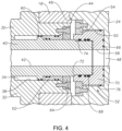
Figure 1 is a perspective view of a marine riser assembly having a termination assembly in accordance with the invention. -
Figure 2 is a section view of a portion of the termination assembly ofFigure 1 , shown with a piston of a terminal block retracted from a floating ring assembly of a ring adapter, in accordance with the invention. -
Figure 3 is a section view of the portion of the termination assembly ofFigure 2 , shown with the piston of the terminal block extended into the floating ring assembly of the ring adapter. -
Figure 4 is a detail section view of the portion of the termination assembly ofFigure 3 , shown with the piston of the terminal block extended into the floating ring assembly of the ring adapter. -
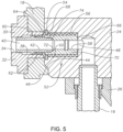
Figure 5 is a section view of a portion of the termination assembly ofFigure 1 , shown with the piston of the terminal block extended into the floating ring assembly of the ring adapter, in accordance with the invention. -
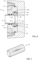
Figure 6 is a section view of a portion of the ring adapter ofFigure 1 , showing the piston of the terminal block extended into the floating ring assembly of the ring adapter, in accordance with the invention. -
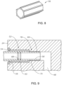
Figure 7 is a perspective view of a spring member of the termination assembly ofFigure 5 , in accordance with the invention. -
Figure 8 is a perspective view of a spring member of the termination assembly ofFigure 5 , in accordance with the invention. -
Figure 9 is a section view of a portion of the ring adapter ofFigure 1 , in accordance with the invention. - The system and method of the invention will now be described more fully hereinafter with reference to the accompanying drawings which illustrate embodiments of the invention. The system and method of this disclosure may, however, be embodied in many different forms and should not be construed as limited to the illustrated embodiments set forth herein. Rather, these embodiments are provided so that this disclosure will be thorough and complete, and will fully convey the scope of the incvention to those skilled in the art. Like numbers refer to like elements throughout, and the prime notation, if used, indicates similar elements in alternative embodiments.
- Referring to
Figure 1 ,marine riser assembly 10 can extend from a subsea assembly todeck 12 of an offshore platform.Deck 12 can be, for example, a drill floor of the offshore platform. Riser 14 can be used to convey hydrocarbons and other fluids from the subsea assembly to the offshore platform. Riserauxiliary lines 16 can be used to convey auxiliary fluids or communication means to and from the subsea assembly. Riser 14 can be supported by the offshore platform throughtermination ring 18. Support members (not shown) can extend between the offshore platform andtermination ring 18 so that the weight oftermination ring 18 andriser 14 is carried by the offshore platform through the support members.Marine riser assembly 10 andtermination ring 18 can be centered on axis Ax. -
Termination ring 18 can be located below aflex joint 20 and diverter 22 ofmarine riser assembly 10.Diverter 22 can be mechanically connected todeck 12 to provide a static connection between the top end ofmarine riser assembly 10 anddeck 12.Flex joint 20 can allow for relative rotational movement betweendeck 12 andmarine riser assembly 10.Termination ring 18 can be connected to ring adapter 24 (Figure 2 ) of specialty riser joint (not shown), slip joint or telescopic joint 26 ofmarine riser assembly 10.Termination ring 18 is a ring shaped member that circumscribes a portion of telescopic joint 26, as will be further described below. Telescopic joint 26 can adjust for a change in length ofmarine riser assembly 10 as the offshore platform moves relative to the subsea assembly. - Platform
auxiliary lines 28 can be used to convey auxiliary fluids or communication means between the offshore platform andtermination ring 18. Platformauxiliary lines 28 can be drape hoses or other flexible lines that allow for relative movement between the offshore platform andmarine riser assembly 10. Riserauxiliary lines 16 can convey auxiliary fluids or communication means betweenring adapter 24 and the subsea assembly. A fluidly sealed connection can be made betweentermination ring 18 andring adapter 24 so that platformauxiliary lines 28 can be in communication with riserauxiliary lines 16 through a fluidly sealed path. Sealing can be provided by elastomeric, metal, or other known sealing means that can seal against the pressures acting throughout the path from platformauxiliary lines 28 through to riser auxiliary lines 16. - Looking at
Figure 2 ,terminal block 30 is secured to an outer diameter oftermination ring 18.Terminal block 30 haspiston housing 32 that extends through a sidewall oftermination ring 18. A seal can be located betweenterminal block 30 andtermination ring 18 to provide a sealed connection betweenterminal block 30 and termination ring 18 (Figure 5 ).Piston housing 32 hashousing bore 34 that extends withinpiston housing 32. An inner end of housing bore 34 opens to an inner diameter surface oftermination ring 18. An outer portion of housing bore 34 ofpiston housing 32 can form a housingauxiliary path 36 which is in communication with platformauxiliary lines 28 through either direct or indirect connection with platform auxiliary lines 28. - An inner portion of housing bore 34 can form
piston chamber 38.Piston 40 is located withinpiston housing 32.Piston 40 has acentral bore 42. Central bore 42 is in communication with housingauxiliary path 36. - Referring to
Figures 4-5 ,termination ring 18 further has upward facingload shoulder 44 on an inner diameter oftermination ring 18. Looking at the example ofFigure 4 ,load shoulder 44 is located axially abovetermination ring 18. In the alternate example offigure 5 ,load shoulder 44 is located axially belowpiston housing 32. - Looking at
Figures 4-5 ,ring adapter 24 has downward facingshoulder 46 on an outer diameter ofring adapter 24.Shoulder 46 is sized and located to mate withload shoulder 44 so that whenring adapter 24 is landed withintermination ring 18,ring adapter 24 is supported bytermination ring 18 onload shoulder 44.Ring adapter 24 has an outer diameter sized to engage an inner diameter oftermination ring 18 whenshoulder 46 ofring adapter 24 is landed onload shoulder 44 oftermination ring 18. -
Ring adapter 24 hasadapter bore 48 that extends withinring adapter 24. An outer end of adapter bore 48 opens to an outer diameter surface ofring adapter 24 and is generally axially and rotationally aligned with housing bore 34 whenring adapter 24 is landed withintermination ring 18. Riserauxiliary line 16 is in communication withadapter bore 48. - Looking at
Figures 4-5 ,piston pocket 50 extends radially inward from the outer diameter ofring adapter 24 at the outer end of adapter bore 48.Piston pocket 50 houses floatingring assembly 52. Floatingring assembly 52 can be retained withinpiston pocket 50 with floatingring retainer 54. Floatingring retainer 54 can be releasably secured to ringadapter 24 and can engage an outer surface of floatingring assembly 52. Floatingring assembly 52 can be moveable withinpiston pocket 50. As an example, an outer diameter of floatingring assembly 52 can be less than an inner diameter ofpiston pocket 50, defining an annular space between the outer diameter of floatingring assembly 52 and the inner diameter of thepiston pocket 50, providing floatingring assembly 52 with space to move within piston pocket 50 (Figures 4 and6 ). In alternate examples,spring member 56 engages the inner diameter ofpiston pocket 50 and provides sufficient flexibility to allowring assembly 52 to move within piston pocket 50 (Figure 5 and9 ). - Floating
ring assembly 52 includes receptacle bore 58 that has a first end that aligns with an adjacent portion of adapter bore 48. Receptacle bore 58 is thereby in communication with riserauxiliary line 16 via adapter bore 48. A second end of receptacle bore 58 is sized to acceptpiston 40. -
Piston 40 can be moved within housing bore 34 between a retracted position (Figure 2 ), and an extended position (Figure 3 ). In the retracted position, an outer end ofpiston 40 can be located withinpiston housing 32, or proximate to the inner diameter surface ofpiston housing 32. In the retracted position, the outer end ofpiston 40 is spaced apart from floatingring assembly 52. In the extended position, an outer surface ofpiston 40 can sealingly engage an inner surface of floatingring assembly 52. - Looking at
Figure 4 , to movepiston 40 between the retracted and extended positions, a pressure media can be injected intopiston chamber 38. Injecting pressure media intopiston chamber 38 radially outward ofpiston seal 60 ofpiston 40 will urgepiston 40 towards the extended position. Injecting pressure media intopiston chamber 38 radially inward ofpiston seal 60 will urgepiston 40 towards the retracted position. A seal or packing 62 forms a seal between the outer diameter ofpiston 40 and the inner diameter ofpiston chamber 38.Piston retainer 64 retains packing 62 andpiston 40 withinpiston chamber 38. - When
piston 40 is in the extended position, a sealed auxiliary path is formed betweenterminal block 30 andring adapter 24. A sealed auxiliary path is also formed between platformauxiliary line 28 and riserauxiliary line 16. Floatingring assembly 52 includes seals that seal leak paths through and between thepiston 40, the floatingring assembly 52, andpiston pocket 50.First seal 66 is located between floatingring assembly 52 andpiston pocket 50. In the example embodiments ofFigures 4-5 ,first seal 66 is a face seal located between an inner face of floatingring assembly 52 and an opposite facing surface ofpiston pocket 50, the face seal circumscribing receptacle bore 58 of floatingring assembly 52. -
Second seal 68 is located between floatingring assembly 52 andpiston 40.Second seal 68 can be located within the inner diameter of receptacle bore 58 and engage an outer diameter ofpiston 40, forming a seal between floatingring assembly 52 andpiston 40. - Looking at the example embodiment of
Figure 4 , floatingring assembly 52 includes floatingring 70. Floatingring 70 houses first seal 66 andsecond seal 68. Floatingring 70 includes floatingring shoulder 72. Floatingring shoulder 72 is an annular surface on an inner diameter of receptacle bore 58. Floatingring shoulder 72 can be sloped or can be generally normal to a central axis of floatingring assembly 52 and can mate withpiston shoulder 74 ofpiston 40.Piston shoulder 74 is an annular surface located onpiston 40. Floatingring shoulder 72 is positioned so that whenpiston 40 is in the extended position;piston shoulder 74 engages floatingring shoulder 72 and pushes floatingring assembly 52 into sealing engagement withpiston pocket 50 by energizingfirst seal 66. Alternately, instead of floatingring shoulder 72 mating withpiston shoulder 74 ofpiston 40, an outer end surface ofpiston 40 can engage an inner end surface of floating ring 70 (Figure 3 ) to push floatingring assembly 52 into sealing engagement withpiston pocket 50 by energizingfirst seal 66. - In the example of
Figure 4 , floatingring shoulder 72 is at an outer end of floatingring 70 of floatingring assembly 52. Aspiston 40 moves from the retracted position to the extended position, the outer end ofpiston 40 may engage floatingring shoulder 72 to assist in aligningpiston 40 within floatingring assembly 52. Floatingring retainer 54 retains floatingring 70 withinpiston pocket 50. However, because the outer diameter of floatingring 70 is less than an inner diameter ofpiston pocket 50,gap 76, which can form an annular space between the outer diameter of floatingring 70 and the inner diameter of thepiston pocket 50, provides floatingring 70 with space to move withinpiston pocket 50. This allowable movement reduces or eliminates the problem of interference between, and galling of,piston 40 and receptacle bore 58. Additionally, because relative movement between floatingring 70 andpiston pocket 50 is allowable and piston receptacle bore 58 can re-orient to align withpiston 40, close machining tolerances are not required, reducing the cost of manufacturing the components of floatingring assembly 52 compared to some current designs. - In the example of
Figures 5 and9 , floatingring 70 is an inner tube. In the example ofFigure 5 , floatingring 70 houses first seal 66 andsecond seal 68.Spring member 56 circumscribes floatingring 70 and is sized to engage the inner diameter ofpiston pocket 50. In the example ofFigure 5 , floatingring 70 includes floatingring shoulder 72, which can mate withpiston shoulder 74 ofpiston 40 to push floatingring assembly 52 into sealing engagement withpiston pocket 50 by energizingfirst seal 66. In such an embodiment, floatingring shoulder 72 is spaced radially inward of an outer end of floatingring 70 of floatingring assembly 52. - In the example of
Figure 5 , floatingring retainer 54 retains floatingring 70 withinpiston pocket 50. However,spring member 56 provides floatingring 70 with the ability to move withinpiston pocket 50.Spring member 56 can be ring shaped or can be an elongated member.Spring member 56 can be, as an example, a marcel spring or expander (Figure 7 ), foam metal, a linear spring (Figure 8 ), a wave spring, spring plungers, or a similar spring type device, or combination thereof. - In the example of
Figure 9 ,first seal 66 is formed by threadedconnection 78 between outer threads of floatingring 70 of floatingring assembly 52 and inner threads on the inner diameter surface ofpiston pocket 50. Because threadedconnection 78 can retain floatingring 70 withinpiston pocket 50, floatingring retainer 54 retainsspring member 56 withinpiston pocket 50, but is not required to retain floatingring 70 withinpiston pocket 50. In such an embodiment, floatingring 70 is formed with the ability to cantilever so that the outer free end of floatingring 70 can move relative to threadedconnection 78. - In the example of
Figure 6 , floatingring assembly 52 includesseal carrier 80 andseal ring 82. Bothseal carrier 80 andseal ring 82 can include afirst seal 66 for sealing between floatingring assembly 52 andpiston pocket 50.First seal 66 includes both aface seal 66a, and acircumferential seal 66b.Face seal 66a is carried byseal carrier 80 between the inner face ofseal carrier 80 and an opposite facing surface ofpiston pocket 50, the face seal circumscribing receptacle bore 58 of floatingring assembly 52.Circumferential seal 66b circumscribes an outer diameter ofseal ring 82.Seal ring 82 housessecond seal 68, which is located within the inner diameter of receptacle bore 58 and engages an outer diameter ofpiston 40, forming a seal between floatingring assembly 52 andpiston 40. - Floating
ring assembly 52 of the example ofFigure 6 includes floatingring shoulder 72. Floatingring shoulder 72 is an annular surface on an inner diameter ofseal carrier 80. Floatingring shoulder 72 can be sloped or can be generally normal to a central axis of floatingring assembly 52 and can mate withpiston shoulder 74 so that whenpiston 40 is in the extended position,piston shoulder 74 engages floatingring shoulder 72 and pushesseal carrier 80 into sealing engagement withpiston pocket 50 by energizingfirst seal 66. - In order to alternately engage
face seal 66a,pressure path 84 can extend through a sidewall ofpiston 40.Pressure path 84 is positioned so that it provides a pressure media path from withincentral bore 42, through the sidewall ofpiston 40, and to an outer end surface ofseal carrier 80 whenpiston 40 is in the extended position, providing a pressure to energizesecond seal 68 and retainface seal 66a in sealing engagement with the opposite facing surface ofpiston pocket 50 with pressure media that is traveling throughcentral bore 42. - Before
piston 40 is moved to the extended position, there can be gaps or spaces between and around each ofseal carrier 80,seal ring 82 andpiston pocket 50 so thatseal carrier 80 andseal ring 82 can move relative to each other and relative topiston pocket 50 so that floatingring 70 has space to move withinpiston pocket 50. This allowable movement reduces or eliminates the problem of interference between, and galling of,piston 40 and receptacle bore 58. - In an example of operation,
ring adapter 24 is attached to telescopic joint 26 belowdiverter 22 and the telescopic joint 26 withring adapter 24 is lowered throughtermination ring 18 untilshoulder 46 ofring adapter 24 lands on, and is supported by,load shoulder 44 oftermination ring 18. Orientation and locking dogs can help to position and alignring adapter 24 withintermination ring 18 as well assecure ring adapter 24 totermination ring 18. -
Piston 40 can then be moved within housing bore 34 between the retracted position and the extended position so that an outer surface ofpiston 40 engages an inner surface of floatingring assembly 52.Piston 40 can be moved to the extended position, for example, by injecting pressure media intopiston chamber 38 radially outward ofpiston seal 60 ofpiston 40. Floatingring assembly 52 allows an inner tube, such as floatingring 70 to float relative to an outer tube, such aspiston pocket 50, and can help to centralizepiston 40. If the centerlines ofpiston 40 and receptacle bore 58 are not on the same axis, the hydraulic actuation ofpiston 40 can push out and initially contact floatingring shoulder 72. Floatingring assembly 52 can adjust to accommodate misalignment so thatpiston 40 does not go into and gall against a rigid object. The float occurring within floatingring assembly 52 does not translate the bending stress from the gooseneck and weight of the platformauxiliary lines 28 into the connection betweenpiston 40 and receptacle bore 58. - Floating
ring assembly 52 is serviceable and replaceable. Although described herein as being part ofring adapter 24, in alternate embodiments, floating ring assembly could be instead adapted to be part ofpiston housing 32. - Therefore the invention provides systems and methods system for aligning an auxiliary line connection in a termination assembly of a marine riser assembly that can result in less downtime and rework, and minimize a "rig down" scenario that causes lost revenue for the operator and contractor, and that can pull engineers off their current projects to focus solely on fixing that problem, compared to some current systems.
- The terms "vertical", "horizontal", "upward", "downward", "above", and "below" and similar spatial relation terminology are used herein only for convenience because elements of the current disclosure may be installed in various relative positions.
- While embodiments of the invention have been shown or described in only some of their forms, it should be apparent to those skilled in the art that it is not so limited, but is susceptible to various changes so long as these changes fall within the scope of the appended claims.
Claims (12)
- A system for aligning an auxiliary line connection in a termination assembly of a marine riser assembly, the system comprising:a terminal block (30) secured to an outer diameter of a termination ring (18), the terminal block (30) having a piston housing (32) that extends through a sidewall of the termination ring (18), and the termination ring (18) having a load shoulder (44) on an inner diameter of the termination ring (18);a ring adapter (24) with a shoulder (46), the ring adapter (24) having an outer diameter sized to engage the inner diameter of the termination ring (18) when the shoulder (46) of the ring adapter (24) is landed on the load shoulder (44) of the termination ring (18);a piston pocket (50) extending radially inward from the outer diameter of the ring adapter (24);a floating ring assembly (52) retained within the piston pocket (50), the floating ring assembly (52) being moveable within the piston pocket (50); anda piston (40) housed within the piston housing (32), the piston (40) having a central bore (42) and being moveable between a retracted position where an outer end of the piston (40) is spaced apart from the floating ring assembly (52), and an extended position where an outer surface of the piston (40) engages an inner surface of the floating ring assembly (52), forming an auxiliary path from the terminal block (30) to the ring adapter (24).
- The system of claim 1, further comprising a face seal (66a) located between an inner face of the floating ring assembly (52) and an opposite facing surface of the piston pocket (50), the face seal circumscribing a receptacle bore (58) of the floating ring assembly.
- The system of claim 1, further comprising a piston shoulder (74) and a floating ring shoulder (74), the piston shoulder (74) being an annular surface located on the piston (40) and the floating ring shoulder (72) being an annular surface located on an inner diameter surface of the floating ring assembly (52) and positioned so that when the piston (40) is in the extended position, the piston shoulder (74) engages the floating ring shoulder (72) and pushes the floating ring assembly (52) into sealing engagement with the piston pocket (50).
- The system of claim 1, further comprising a floating ring shoulder (72) located on an inner diameter surface of the floating ring assembly (52) at an outer end of the floating ring assembly (52), the floating ring shoulder (72) being an annular surface engagable by the outer end of the piston (40) as the piston moves (40) from the retracted position to the extended position (40) to align the piston within the floating ring assembly (52).
- The system of claim 1, further comprising a floating ring retainer (54), the floating ring retainer (54) being releasably secured to the ring adapter (24) and engaging an outer surface of the floating ring assembly (52).
- The system of claim 1, wherein the floating ring assembly (52) includes a seal ring (82) having a piston seal (60) on an inner diameter of the seal ring (82) for sealingly engaging the outer diameter of the piston (40), the floating ring assembly (52) further comprising a seal carrier (80) having a face seal (66a) located on an inner end surface of the seal carrier (80) and an outer diameter seal that forms a fluid seal between an outer diameter of the seal carrier (80) and the inner diameter of the seal ring (82).
- The system of claim 1, wherein an outer diameter of the floating ring assembly (52) is less than an inner diameter of the piston pocket (50), defining an annular space between the outer diameter of the floating ring assembly (52) and the inner diameter of the piston pocket (50).
- The system of claim 1, wherein the floating ring assembly (52) includes an inner tube having a piston seal on an inner diameter of the inner tube for sealingly engaging an outer diameter of the piston (40), and wherein the system further includes a spring member (56) circumscribing the inner tube and sized to engage an inner diameter of the piston pocket (50).
- A method for aligning an auxiliary line connection in a termination assembly of a marine riser assembly, the method comprising:securing a terminal block (30) to an outer diameter of a termination ring (18), the terminal block (30) having a piston housing (32) that extends through a sidewall of the termination ring (18), and the termination ring (18) having a load shoulder (44) on an inner diameter of the termination ring (18);landing a shoulder (46) of a ring adapter (24) on the load shoulder (44) of the termination ring (18), the ring adapter (24) having an outer diameter sized to engage the inner diameter of the termination ring (18), the ring adapter (24) having a piston pocket (50) extending radially inward from the outer diameter of the ring adapter (24), and a floating ring assembly (52) retained within the piston pocket (50), the floating ring assembly (52) moveable within the piston pocket (50); andmoving a piston (40) between a retracted position where an outer end of the piston (40) is located within the piston housing (32), and an extended position where an outer surface of the piston (40) engages an inner surface of the floating ring assembly (52), forming an auxiliary path from the terminal block (30) to the ring adapter (24), the piston (40) being located within the piston housing (32) and having a central bore (42).
- The method of claim 9, further comprising forming a seal between an inner face of the floating ring assembly (52) and an opposite facing surface of the piston pocket (50) with a face seal, the face seal circumscribing a receptacle bore of the floating ring assembly (52).
- The method of claim 9, further comprising engaging a floating ring shoulder (72) with a piston shoulder (74) to push the floating ring assembly (52) into sealing engagement with the piston pocket (50), the piston shoulder (74)being an annular sloped surface located on the piston (40) and the floating ring shoulder (72) being an annular sloped surface located on an inner diameter surface of the floating ring assembly (52).
- The method of claim 9, wherein the floating ring assembly (52) includes a seal ring (82) having a piston seal (60) on an inner diameter of the seal ring (82) that sealingly engages the outer diameter of the piston (40), and wherein the floating ring assembly (52) further includes a seal carrier (80) having a face seal (66a) located on an inner end surface of the seal carrier (80) and an outer diameter seal that forms a fluid seal between an outer diameter of the seal carrier (80) and the inner diameter of the seal ring (82).
Applications Claiming Priority (4)
| Application Number | Priority Date | Filing Date | Title |
|---|---|---|---|
| US201462091160P | 2014-12-12 | 2014-12-12 | |
| US201462097845P | 2014-12-30 | 2014-12-30 | |
| US14/963,849 US9759018B2 (en) | 2014-12-12 | 2015-12-09 | System and method of alignment for hydraulic coupling |
| PCT/US2015/065227 WO2016094790A1 (en) | 2014-12-12 | 2015-12-11 | System and method of alignment for an auxiliary lines hydraulic coupling |
Publications (2)
| Publication Number | Publication Date |
|---|---|
| EP3230552A1 EP3230552A1 (en) | 2017-10-18 |
| EP3230552B1 true EP3230552B1 (en) | 2023-07-26 |
Family
ID=55071172
Family Applications (1)
| Application Number | Title | Priority Date | Filing Date |
|---|---|---|---|
| EP15820718.3A Active EP3230552B1 (en) | 2014-12-12 | 2015-12-11 | System and method of alignment for an auxiliary lines hydraulic coupling |
Country Status (5)
| Country | Link |
|---|---|
| US (1) | US9759018B2 (en) |
| EP (1) | EP3230552B1 (en) |
| BR (1) | BR112017012276B1 (en) |
| SG (1) | SG11201704369TA (en) |
| WO (1) | WO2016094790A1 (en) |
Families Citing this family (6)
| Publication number | Priority date | Publication date | Assignee | Title |
|---|---|---|---|---|
| US10876369B2 (en) | 2014-09-30 | 2020-12-29 | Hydril USA Distribution LLC | High pressure blowout preventer system |
| US10196871B2 (en) | 2014-09-30 | 2019-02-05 | Hydril USA Distribution LLC | Sil rated system for blowout preventer control |
| US11628697B2 (en) * | 2016-11-07 | 2023-04-18 | William K Chapin | Hydraulic gooseneck trailer coupler system and method |
| NL2019427B1 (en) * | 2017-08-18 | 2019-02-25 | Itrec Bv | Running a subsea riser string. |
| WO2020172497A1 (en) * | 2019-02-21 | 2020-08-27 | Weatherford Technology Holdings, Llc | Self-aligning, multi-stab connections for managed pressure drilling between rig and riser components |
| NO346471B1 (en) | 2019-11-18 | 2022-08-29 | Future Production As | Termination body for a riser and method for connecting the termination body to the riser |
Citations (3)
| Publication number | Priority date | Publication date | Assignee | Title |
|---|---|---|---|---|
| US4592426A (en) * | 1984-12-10 | 1986-06-03 | Hughes Tool Company | Upper termination with sliding sleeve seals |
| US5314024A (en) * | 1992-08-10 | 1994-05-24 | Cooper Industries, Inc. | Angular and radial self-aligning coupling |
| US20140083711A1 (en) * | 2012-09-21 | 2014-03-27 | National Oilwell Varco, L.P. | Hands free gooseneck with rotating cartridge assemblies |
Family Cites Families (79)
| Publication number | Priority date | Publication date | Assignee | Title |
|---|---|---|---|---|
| US3643751A (en) * | 1969-12-15 | 1972-02-22 | Charles D Crickmer | Hydrostatic riser pipe tensioner |
| US3902554A (en) | 1974-03-12 | 1975-09-02 | Global Marine Inc | Blowout preventer guide assembly for off-shore drilling vessel |
| US4109938A (en) | 1975-09-25 | 1978-08-29 | Mitchell Beazley Encyclopedias, Ltd. | System for arranging and retrieving information |
| US4618173A (en) | 1980-10-14 | 1986-10-21 | Big-Inch Marine Systems, Inc. | Swivel coupling element |
| US4709726A (en) * | 1987-02-17 | 1987-12-01 | Ferranti Subsea Systems, Inc. | Hydraulic coupler with floating metal seal |
| US5539427A (en) | 1992-02-10 | 1996-07-23 | Compaq Computer Corporation | Graphic indexing system |
| US5781192A (en) | 1996-01-16 | 1998-07-14 | Canon Information Systems, Inc. | Data transfer system |
| US5778918A (en) | 1996-10-18 | 1998-07-14 | Varco Shaffer, Inc. | Pilot valve with improved cage |
| US6041804A (en) * | 1998-02-23 | 2000-03-28 | Chatufale; Vijay R. | Subsea valve actuator and method |
| GB9814114D0 (en) | 1998-07-01 | 1998-08-26 | Abb Seatec Ltd | Wells |
| US6040969A (en) | 1998-08-04 | 2000-03-21 | Electronic Systems Protection, Inc. | Power filter circuit responsive to supply system fault conditions |
| US6957205B1 (en) | 2000-03-08 | 2005-10-18 | Accenture Llp | Knowledge model-based indexing of information |
| JP2002110592A (en) | 2000-09-27 | 2002-04-12 | Sony Corp | Polishing method and polishing apparatus |
| NO314708B1 (en) | 2001-05-30 | 2003-05-05 | Statoil Asa | Signal transmission under water |
| US6990498B2 (en) | 2001-06-15 | 2006-01-24 | Sony Corporation | Dynamic graphical index of website content |
| US6961226B2 (en) | 2002-11-12 | 2005-11-01 | General Electric Company | Method and system for providing power to circuit breakers |
| US7887103B2 (en) | 2003-05-22 | 2011-02-15 | Watherford/Lamb, Inc. | Energizing seal for expandable connections |
| US7261162B2 (en) | 2003-06-25 | 2007-08-28 | Schlumberger Technology Corporation | Subsea communications system |
| KR20100127321A (en) | 2003-09-05 | 2010-12-03 | 마이크로 모우션, 인코포레이티드 | Flow meter filter system and method |
| US6923476B2 (en) * | 2003-09-12 | 2005-08-02 | National Coupling Company, Inc. | Floating seal for undersea hydraulic coupling |
| US7000890B2 (en) * | 2004-01-14 | 2006-02-21 | Cooper Cameron Corporation | Pressure compensated shear seal solenoid valve |
| US7216714B2 (en) | 2004-08-20 | 2007-05-15 | Oceaneering International, Inc. | Modular, distributed, ROV retrievable subsea control system, associated deepwater subsea blowout preventer stack configuration, and methods of use |
| GB2417656B (en) | 2004-08-24 | 2009-02-11 | Vetco Gray Controls Ltd | Communication apparatus |
| FR2883441A1 (en) | 2005-03-17 | 2006-09-22 | Thomson Licensing Sa | METHOD FOR SELECTING PARTS OF AUDIOVISUAL TRANSMISSION AND DEVICE IMPLEMENTING THE METHOD |
| GB2443776B (en) | 2005-08-23 | 2009-12-09 | Vetco Gray Inc | Preloaded riser coupling system |
| US7571772B2 (en) | 2005-09-19 | 2009-08-11 | Vetco Gray Inc. | System, method, and apparatus for a radially-movable line termination system for a riser string on a drilling rig |
| WO2007076488A2 (en) | 2005-12-22 | 2007-07-05 | Transocean Offshore Deepwater Drilling Inc | Dual-bop and common riser system |
| US7849599B2 (en) | 2006-09-28 | 2010-12-14 | Hydril Usa Manufacturing Llc | Imputing strength gradient in pressure vessels |
| US7832706B2 (en) | 2007-02-16 | 2010-11-16 | Hydrill USA Manufacturing LLC | RAM BOP position sensor |
| WO2009025732A1 (en) | 2007-08-09 | 2009-02-26 | Dtc International, Inc. | Control system for blowout preventer stack |
| US8157295B2 (en) | 2008-03-05 | 2012-04-17 | Hiltap Fittings, Ltd. | Articulating joint with injector port |
| NO345599B1 (en) | 2008-04-18 | 2021-05-03 | Schlumberger Technology Bv | Underground test valve tree system and method of operating a subsea test valve tree |
| CA2632634C (en) | 2008-05-26 | 2013-09-17 | Orren Johnson | Adjustable angle drive connection for a down hole drilling motor |
| US7913767B2 (en) * | 2008-06-16 | 2011-03-29 | Vetco Gray Inc. | System and method for connecting tubular members |
| CN201250646Y (en) | 2008-07-31 | 2009-06-03 | 河北华北石油荣盛机械制造有限公司 | Underwater hydraulic pressure directional control valve |
| US8469048B2 (en) * | 2008-12-12 | 2013-06-25 | Parker-Hannifin Corporation | Pressure feedback shuttle valve |
| US8054593B2 (en) | 2008-12-29 | 2011-11-08 | Reid Paul A | Apparatus and method for measuring load current using a ground fault sensing transformer |
| US8812274B2 (en) | 2009-04-24 | 2014-08-19 | Hermant Virkar | Methods for mapping data into lower dimensions |
| US20100300696A1 (en) | 2009-05-27 | 2010-12-02 | Schlumberger Technology Corporation | System and Method for Monitoring Subsea Valves |
| US8322436B2 (en) | 2009-06-29 | 2012-12-04 | Vetco Gray Inc. | Split assembly attachment device |
| US8388255B2 (en) | 2009-07-13 | 2013-03-05 | Vetco Gray Inc. | Dog-type lockout and position indicator assembly |
| EP2317286A1 (en) | 2009-10-29 | 2011-05-04 | Services Pétroliers Schlumberger | A method of dynamically correcting flow rate measurements |
| NO331541B1 (en) * | 2009-11-10 | 2012-01-23 | Future Production As | Kill / leash interconnect device between a riser and a floating drilling vessel |
| WO2011072145A2 (en) | 2009-12-09 | 2011-06-16 | Schlumberger Canada Limited | Dual path subsea control system |
| US20110266002A1 (en) | 2010-04-30 | 2011-11-03 | Hydril Usa Manufacturing Llc | Subsea Control Module with Removable Section |
| US8464797B2 (en) | 2010-04-30 | 2013-06-18 | Hydril Usa Manufacturing Llc | Subsea control module with removable section and method |
| US9057751B2 (en) | 2010-04-30 | 2015-06-16 | Schlumberger Technology Corporation | Ground fault detection for an electrical subsea control system |
| NO332485B1 (en) | 2010-07-18 | 2012-09-21 | Marine Cybernetics As | Method and system for testing a control system for a blowout protection |
| US8403053B2 (en) | 2010-12-17 | 2013-03-26 | Hydril Usa Manufacturing Llc | Circuit functional test system and method |
| EP2541263A1 (en) | 2011-07-01 | 2013-01-02 | Siemens Aktiengesellschaft | Fault detection system and method, and power system for subsea pipeline direct electrical heating cables |
| US8781743B2 (en) | 2011-01-27 | 2014-07-15 | Bp Corporation North America Inc. | Monitoring the health of a blowout preventer |
| US8539000B2 (en) | 2011-03-10 | 2013-09-17 | Textwise Llc | Method and system for information modeling and applications thereof |
| EP2523357B1 (en) | 2011-05-12 | 2013-09-18 | Siemens Aktiengesellschaft | Subsea data communication system and method |
| US20120312546A1 (en) | 2011-06-07 | 2012-12-13 | Baker Hughes Incorporated | Water hammer mitigating flow control structure and method |
| US8863845B2 (en) * | 2011-10-17 | 2014-10-21 | Cameron International Corporation | Gooseneck conduit system |
| US20130054034A1 (en) | 2011-08-30 | 2013-02-28 | Hydril Usa Manufacturing Llc | Method, device and system for monitoring subsea components |
| US9033049B2 (en) | 2011-11-10 | 2015-05-19 | Johnnie E. Kotrla | Blowout preventer shut-in assembly of last resort |
| US20140361785A1 (en) | 2012-01-31 | 2014-12-11 | Damir Radan | Fault Detection in Subsea Power Cables |
| US20130253872A1 (en) | 2012-03-20 | 2013-09-26 | Thermo Fisher Scientific Inc. | Flow meter calibration system |
| US10012072B2 (en) | 2012-03-22 | 2018-07-03 | Exxonmobil Upstream Research Company | Multi-phase flow meter and methods for use thereof |
| US10087687B2 (en) * | 2012-04-02 | 2018-10-02 | Cameron International Corporation | Seal sub system |
| US9163471B2 (en) | 2012-04-27 | 2015-10-20 | Cameron International Corporation | Position monitoring system and method |
| US9708863B2 (en) * | 2012-05-14 | 2017-07-18 | Dril-Quip Inc. | Riser monitoring system and method |
| WO2013192494A1 (en) | 2012-06-22 | 2013-12-27 | The Subsea Company | Soft shift spm valve |
| US8944403B2 (en) * | 2012-07-19 | 2015-02-03 | Cameron International Corporation | Blowout preventer with pressure-isolated operating piston assembly |
| US9970287B2 (en) | 2012-08-28 | 2018-05-15 | Cameron International Corporation | Subsea electronic data system |
| US9422783B2 (en) | 2012-08-30 | 2016-08-23 | Hydril Usa Distribution, Llc | Stabilized valve |
| KR102222094B1 (en) | 2012-11-12 | 2021-03-04 | 카메론 테크놀로지스 리미티드 | Blowout preventer system with three control pods |
| EP2738780B1 (en) | 2012-11-28 | 2016-03-16 | ABB Technology AG | Subsea pressure compensation arrangement |
| GB2508919A (en) * | 2012-12-17 | 2014-06-18 | Flexible Engineered Solutions Ltd | Subsea connector assembly |
| US20150101674A1 (en) * | 2012-12-20 | 2015-04-16 | Hydril Usa Distribution, Llc | Subsea pressure regulator |
| US9109420B2 (en) * | 2013-01-30 | 2015-08-18 | Rowan Deepwater Drilling (Gibraltar) Ltd. | Riser fluid handling system |
| US20150233202A1 (en) | 2013-03-15 | 2015-08-20 | Safestack Technology L.L.C. | Riser disconnect package for lower marine riser package, and annular-release flex-joint assemblies |
| NO20130878A1 (en) * | 2013-06-24 | 2014-12-25 | Fmc Kongsberg Subsea As | Submarine link |
| US9496702B2 (en) | 2013-07-15 | 2016-11-15 | General Electric Company | Method and system for control and protection of direct current subsea power systems |
| US9650856B2 (en) | 2013-11-12 | 2017-05-16 | Cameron International Corporation | Assembly and system including a surge relief valve |
| US9410393B2 (en) * | 2013-12-12 | 2016-08-09 | Hydril USA Distribution LLC | Pressure assisted blowout preventer |
| CN106164411B (en) | 2014-01-02 | 2019-09-24 | 海德里尔美国配送有限责任公司 | For showing the component health of seabed control subsystem component and the system and method for preventive maintenance needs |
| US9482068B2 (en) * | 2014-12-19 | 2016-11-01 | Vetco Gray, Inc. | Hydraulic lockdown |
-
2015
- 2015-12-09 US US14/963,849 patent/US9759018B2/en active Active
- 2015-12-11 WO PCT/US2015/065227 patent/WO2016094790A1/en not_active Ceased
- 2015-12-11 SG SG11201704369TA patent/SG11201704369TA/en unknown
- 2015-12-11 BR BR112017012276-6A patent/BR112017012276B1/en not_active IP Right Cessation
- 2015-12-11 EP EP15820718.3A patent/EP3230552B1/en active Active
Patent Citations (3)
| Publication number | Priority date | Publication date | Assignee | Title |
|---|---|---|---|---|
| US4592426A (en) * | 1984-12-10 | 1986-06-03 | Hughes Tool Company | Upper termination with sliding sleeve seals |
| US5314024A (en) * | 1992-08-10 | 1994-05-24 | Cooper Industries, Inc. | Angular and radial self-aligning coupling |
| US20140083711A1 (en) * | 2012-09-21 | 2014-03-27 | National Oilwell Varco, L.P. | Hands free gooseneck with rotating cartridge assemblies |
Also Published As
| Publication number | Publication date |
|---|---|
| WO2016094790A1 (en) | 2016-06-16 |
| EP3230552A1 (en) | 2017-10-18 |
| SG11201704369TA (en) | 2017-06-29 |
| US20160168926A1 (en) | 2016-06-16 |
| BR112017012276A2 (en) | 2018-02-06 |
| US9759018B2 (en) | 2017-09-12 |
| BR112017012276B1 (en) | 2022-05-03 |
Similar Documents
| Publication | Publication Date | Title |
|---|---|---|
| EP3230552B1 (en) | System and method of alignment for an auxiliary lines hydraulic coupling | |
| US5727630A (en) | Telescopic joint control line system | |
| EP2834448B1 (en) | Wellsite connector with floating seal member and method of using same | |
| GB2515418B (en) | Seal sub system | |
| EP3563027B1 (en) | Running tool assemblies and methods | |
| US20160258562A1 (en) | Riser connector assembly | |
| US8499838B2 (en) | Subsea locking connector | |
| US9702205B2 (en) | Offshore well system with connection system | |
| US10072475B2 (en) | Integrated managed pressure drilling riser joint | |
| EP0583121B1 (en) | Angular and radial self-aligning coupling | |
| WO2015077347A1 (en) | Stab connector assembly and method usable for establishing a fluid connection | |
| US8960303B2 (en) | Gooseneck conduit system | |
| EP3853434B1 (en) | Connection system for a marine drilling riser | |
| EP0184973B1 (en) | Supporting system for a riser | |
| US7377323B2 (en) | Blowout preventer stack landing assist tool | |
| EP3234304A1 (en) | Hydraulic lockdown | |
| US20230212917A1 (en) | Gooseneck connector system | |
| US20180045013A1 (en) | Valved tree member for a riser system and telescoping device for inclusion in a riser system | |
| US20160153256A1 (en) | Mono bore riser adapter | |
| WO2014014357A1 (en) | High pressure riser assembly |
Legal Events
| Date | Code | Title | Description |
|---|---|---|---|
| STAA | Information on the status of an ep patent application or granted ep patent |
Free format text: STATUS: THE INTERNATIONAL PUBLICATION HAS BEEN MADE |
|
| PUAI | Public reference made under article 153(3) epc to a published international application that has entered the european phase |
Free format text: ORIGINAL CODE: 0009012 |
|
| STAA | Information on the status of an ep patent application or granted ep patent |
Free format text: STATUS: REQUEST FOR EXAMINATION WAS MADE |
|
| 17P | Request for examination filed |
Effective date: 20170712 |
|
| AK | Designated contracting states |
Kind code of ref document: A1 Designated state(s): AL AT BE BG CH CY CZ DE DK EE ES FI FR GB GR HR HU IE IS IT LI LT LU LV MC MK MT NL NO PL PT RO RS SE SI SK SM TR |
|
| AX | Request for extension of the european patent |
Extension state: BA ME |
|
| DAV | Request for validation of the european patent (deleted) | ||
| DAX | Request for extension of the european patent (deleted) | ||
| STAA | Information on the status of an ep patent application or granted ep patent |
Free format text: STATUS: EXAMINATION IS IN PROGRESS |
|
| 17Q | First examination report despatched |
Effective date: 20190129 |
|
| RIN1 | Information on inventor provided before grant (corrected) |
Inventor name: GAMBLE, JAMIE CLAY Inventor name: LARSON, ERIC DALE Inventor name: STIBICH, ALEX DAVID |
|
| GRAP | Despatch of communication of intention to grant a patent |
Free format text: ORIGINAL CODE: EPIDOSNIGR1 |
|
| STAA | Information on the status of an ep patent application or granted ep patent |
Free format text: STATUS: GRANT OF PATENT IS INTENDED |
|
| INTG | Intention to grant announced |
Effective date: 20230220 |
|
| GRAS | Grant fee paid |
Free format text: ORIGINAL CODE: EPIDOSNIGR3 |
|
| GRAA | (expected) grant |
Free format text: ORIGINAL CODE: 0009210 |
|
| STAA | Information on the status of an ep patent application or granted ep patent |
Free format text: STATUS: THE PATENT HAS BEEN GRANTED |
|
| AK | Designated contracting states |
Kind code of ref document: B1 Designated state(s): AL AT BE BG CH CY CZ DE DK EE ES FI FR GB GR HR HU IE IS IT LI LT LU LV MC MK MT NL NO PL PT RO RS SE SI SK SM TR |
|
| REG | Reference to a national code |
Ref country code: GB Ref legal event code: FG4D |
|
| REG | Reference to a national code |
Ref country code: CH Ref legal event code: EP |
|
| REG | Reference to a national code |
Ref country code: DE Ref legal event code: R096 Ref document number: 602015084801 Country of ref document: DE |
|
| REG | Reference to a national code |
Ref country code: IE Ref legal event code: FG4D |
|
| REG | Reference to a national code |
Ref country code: LT Ref legal event code: MG9D |
|
| REG | Reference to a national code |
Ref country code: NO Ref legal event code: T2 Effective date: 20230726 |
|
| REG | Reference to a national code |
Ref country code: NL Ref legal event code: MP Effective date: 20230726 |
|
| REG | Reference to a national code |
Ref country code: AT Ref legal event code: MK05 Ref document number: 1592103 Country of ref document: AT Kind code of ref document: T Effective date: 20230726 |
|
| PG25 | Lapsed in a contracting state [announced via postgrant information from national office to epo] |
Ref country code: NL Free format text: LAPSE BECAUSE OF FAILURE TO SUBMIT A TRANSLATION OF THE DESCRIPTION OR TO PAY THE FEE WITHIN THE PRESCRIBED TIME-LIMIT Effective date: 20230726 |
|
| PG25 | Lapsed in a contracting state [announced via postgrant information from national office to epo] |
Ref country code: GR Free format text: LAPSE BECAUSE OF FAILURE TO SUBMIT A TRANSLATION OF THE DESCRIPTION OR TO PAY THE FEE WITHIN THE PRESCRIBED TIME-LIMIT Effective date: 20231027 |
|
| PG25 | Lapsed in a contracting state [announced via postgrant information from national office to epo] |
Ref country code: IS Free format text: LAPSE BECAUSE OF FAILURE TO SUBMIT A TRANSLATION OF THE DESCRIPTION OR TO PAY THE FEE WITHIN THE PRESCRIBED TIME-LIMIT Effective date: 20231126 |
|
| PG25 | Lapsed in a contracting state [announced via postgrant information from national office to epo] |
Ref country code: SE Free format text: LAPSE BECAUSE OF FAILURE TO SUBMIT A TRANSLATION OF THE DESCRIPTION OR TO PAY THE FEE WITHIN THE PRESCRIBED TIME-LIMIT Effective date: 20230726 Ref country code: RS Free format text: LAPSE BECAUSE OF FAILURE TO SUBMIT A TRANSLATION OF THE DESCRIPTION OR TO PAY THE FEE WITHIN THE PRESCRIBED TIME-LIMIT Effective date: 20230726 Ref country code: PT Free format text: LAPSE BECAUSE OF FAILURE TO SUBMIT A TRANSLATION OF THE DESCRIPTION OR TO PAY THE FEE WITHIN THE PRESCRIBED TIME-LIMIT Effective date: 20231127 Ref country code: LV Free format text: LAPSE BECAUSE OF FAILURE TO SUBMIT A TRANSLATION OF THE DESCRIPTION OR TO PAY THE FEE WITHIN THE PRESCRIBED TIME-LIMIT Effective date: 20230726 Ref country code: LT Free format text: LAPSE BECAUSE OF FAILURE TO SUBMIT A TRANSLATION OF THE DESCRIPTION OR TO PAY THE FEE WITHIN THE PRESCRIBED TIME-LIMIT Effective date: 20230726 Ref country code: IS Free format text: LAPSE BECAUSE OF FAILURE TO SUBMIT A TRANSLATION OF THE DESCRIPTION OR TO PAY THE FEE WITHIN THE PRESCRIBED TIME-LIMIT Effective date: 20231126 Ref country code: HR Free format text: LAPSE BECAUSE OF FAILURE TO SUBMIT A TRANSLATION OF THE DESCRIPTION OR TO PAY THE FEE WITHIN THE PRESCRIBED TIME-LIMIT Effective date: 20230726 Ref country code: GR Free format text: LAPSE BECAUSE OF FAILURE TO SUBMIT A TRANSLATION OF THE DESCRIPTION OR TO PAY THE FEE WITHIN THE PRESCRIBED TIME-LIMIT Effective date: 20231027 Ref country code: FI Free format text: LAPSE BECAUSE OF FAILURE TO SUBMIT A TRANSLATION OF THE DESCRIPTION OR TO PAY THE FEE WITHIN THE PRESCRIBED TIME-LIMIT Effective date: 20230726 Ref country code: AT Free format text: LAPSE BECAUSE OF FAILURE TO SUBMIT A TRANSLATION OF THE DESCRIPTION OR TO PAY THE FEE WITHIN THE PRESCRIBED TIME-LIMIT Effective date: 20230726 |
|
| PG25 | Lapsed in a contracting state [announced via postgrant information from national office to epo] |
Ref country code: PL Free format text: LAPSE BECAUSE OF FAILURE TO SUBMIT A TRANSLATION OF THE DESCRIPTION OR TO PAY THE FEE WITHIN THE PRESCRIBED TIME-LIMIT Effective date: 20230726 |
|
| PG25 | Lapsed in a contracting state [announced via postgrant information from national office to epo] |
Ref country code: ES Free format text: LAPSE BECAUSE OF FAILURE TO SUBMIT A TRANSLATION OF THE DESCRIPTION OR TO PAY THE FEE WITHIN THE PRESCRIBED TIME-LIMIT Effective date: 20230726 |
|
| REG | Reference to a national code |
Ref country code: DE Ref legal event code: R097 Ref document number: 602015084801 Country of ref document: DE |
|
| PG25 | Lapsed in a contracting state [announced via postgrant information from national office to epo] |
Ref country code: SM Free format text: LAPSE BECAUSE OF FAILURE TO SUBMIT A TRANSLATION OF THE DESCRIPTION OR TO PAY THE FEE WITHIN THE PRESCRIBED TIME-LIMIT Effective date: 20230726 Ref country code: RO Free format text: LAPSE BECAUSE OF FAILURE TO SUBMIT A TRANSLATION OF THE DESCRIPTION OR TO PAY THE FEE WITHIN THE PRESCRIBED TIME-LIMIT Effective date: 20230726 Ref country code: ES Free format text: LAPSE BECAUSE OF FAILURE TO SUBMIT A TRANSLATION OF THE DESCRIPTION OR TO PAY THE FEE WITHIN THE PRESCRIBED TIME-LIMIT Effective date: 20230726 Ref country code: EE Free format text: LAPSE BECAUSE OF FAILURE TO SUBMIT A TRANSLATION OF THE DESCRIPTION OR TO PAY THE FEE WITHIN THE PRESCRIBED TIME-LIMIT Effective date: 20230726 Ref country code: DK Free format text: LAPSE BECAUSE OF FAILURE TO SUBMIT A TRANSLATION OF THE DESCRIPTION OR TO PAY THE FEE WITHIN THE PRESCRIBED TIME-LIMIT Effective date: 20230726 Ref country code: CZ Free format text: LAPSE BECAUSE OF FAILURE TO SUBMIT A TRANSLATION OF THE DESCRIPTION OR TO PAY THE FEE WITHIN THE PRESCRIBED TIME-LIMIT Effective date: 20230726 Ref country code: SK Free format text: LAPSE BECAUSE OF FAILURE TO SUBMIT A TRANSLATION OF THE DESCRIPTION OR TO PAY THE FEE WITHIN THE PRESCRIBED TIME-LIMIT Effective date: 20230726 |
|
| PG25 | Lapsed in a contracting state [announced via postgrant information from national office to epo] |
Ref country code: IT Free format text: LAPSE BECAUSE OF FAILURE TO SUBMIT A TRANSLATION OF THE DESCRIPTION OR TO PAY THE FEE WITHIN THE PRESCRIBED TIME-LIMIT Effective date: 20230726 |
|
| PLBE | No opposition filed within time limit |
Free format text: ORIGINAL CODE: 0009261 |
|
| STAA | Information on the status of an ep patent application or granted ep patent |
Free format text: STATUS: NO OPPOSITION FILED WITHIN TIME LIMIT |
|
| REG | Reference to a national code |
Ref country code: DE Ref legal event code: R119 Ref document number: 602015084801 Country of ref document: DE |
|
| 26N | No opposition filed |
Effective date: 20240429 |
|
| PG25 | Lapsed in a contracting state [announced via postgrant information from national office to epo] |
Ref country code: SI Free format text: LAPSE BECAUSE OF FAILURE TO SUBMIT A TRANSLATION OF THE DESCRIPTION OR TO PAY THE FEE WITHIN THE PRESCRIBED TIME-LIMIT Effective date: 20230726 |
|
| REG | Reference to a national code |
Ref country code: CH Ref legal event code: PL |
|
| PG25 | Lapsed in a contracting state [announced via postgrant information from national office to epo] |
Ref country code: LU Free format text: LAPSE BECAUSE OF NON-PAYMENT OF DUE FEES Effective date: 20231211 |
|
| PG25 | Lapsed in a contracting state [announced via postgrant information from national office to epo] |
Ref country code: MC Free format text: LAPSE BECAUSE OF FAILURE TO SUBMIT A TRANSLATION OF THE DESCRIPTION OR TO PAY THE FEE WITHIN THE PRESCRIBED TIME-LIMIT Effective date: 20230726 |
|
| GBPC | Gb: european patent ceased through non-payment of renewal fee |
Effective date: 20231211 |
|
| REG | Reference to a national code |
Ref country code: BE Ref legal event code: MM Effective date: 20231231 |
|
| PG25 | Lapsed in a contracting state [announced via postgrant information from national office to epo] |
Ref country code: MC Free format text: LAPSE BECAUSE OF FAILURE TO SUBMIT A TRANSLATION OF THE DESCRIPTION OR TO PAY THE FEE WITHIN THE PRESCRIBED TIME-LIMIT Effective date: 20230726 Ref country code: LU Free format text: LAPSE BECAUSE OF NON-PAYMENT OF DUE FEES Effective date: 20231211 |
|
| REG | Reference to a national code |
Ref country code: IE Ref legal event code: MM4A |
|
| PG25 | Lapsed in a contracting state [announced via postgrant information from national office to epo] |
Ref country code: DE Free format text: LAPSE BECAUSE OF NON-PAYMENT OF DUE FEES Effective date: 20240702 Ref country code: IE Free format text: LAPSE BECAUSE OF NON-PAYMENT OF DUE FEES Effective date: 20231211 |
|
| PG25 | Lapsed in a contracting state [announced via postgrant information from national office to epo] |
Ref country code: GB Free format text: LAPSE BECAUSE OF NON-PAYMENT OF DUE FEES Effective date: 20231211 |
|
| PG25 | Lapsed in a contracting state [announced via postgrant information from national office to epo] |
Ref country code: BE Free format text: LAPSE BECAUSE OF NON-PAYMENT OF DUE FEES Effective date: 20231231 |
|
| PG25 | Lapsed in a contracting state [announced via postgrant information from national office to epo] |
Ref country code: FR Free format text: LAPSE BECAUSE OF NON-PAYMENT OF DUE FEES Effective date: 20231231 |
|
| PG25 | Lapsed in a contracting state [announced via postgrant information from national office to epo] |
Ref country code: CH Free format text: LAPSE BECAUSE OF NON-PAYMENT OF DUE FEES Effective date: 20231231 |
|
| PG25 | Lapsed in a contracting state [announced via postgrant information from national office to epo] |
Ref country code: IE Free format text: LAPSE BECAUSE OF NON-PAYMENT OF DUE FEES Effective date: 20231211 Ref country code: GB Free format text: LAPSE BECAUSE OF NON-PAYMENT OF DUE FEES Effective date: 20231211 Ref country code: FR Free format text: LAPSE BECAUSE OF NON-PAYMENT OF DUE FEES Effective date: 20231231 Ref country code: DE Free format text: LAPSE BECAUSE OF NON-PAYMENT OF DUE FEES Effective date: 20240702 Ref country code: CH Free format text: LAPSE BECAUSE OF NON-PAYMENT OF DUE FEES Effective date: 20231231 Ref country code: BE Free format text: LAPSE BECAUSE OF NON-PAYMENT OF DUE FEES Effective date: 20231231 |
|
| PG25 | Lapsed in a contracting state [announced via postgrant information from national office to epo] |
Ref country code: BG Free format text: LAPSE BECAUSE OF FAILURE TO SUBMIT A TRANSLATION OF THE DESCRIPTION OR TO PAY THE FEE WITHIN THE PRESCRIBED TIME-LIMIT Effective date: 20230726 |
|
| PG25 | Lapsed in a contracting state [announced via postgrant information from national office to epo] |
Ref country code: BG Free format text: LAPSE BECAUSE OF FAILURE TO SUBMIT A TRANSLATION OF THE DESCRIPTION OR TO PAY THE FEE WITHIN THE PRESCRIBED TIME-LIMIT Effective date: 20230726 |
|
| PG25 | Lapsed in a contracting state [announced via postgrant information from national office to epo] |
Ref country code: CY Free format text: LAPSE BECAUSE OF FAILURE TO SUBMIT A TRANSLATION OF THE DESCRIPTION OR TO PAY THE FEE WITHIN THE PRESCRIBED TIME-LIMIT; INVALID AB INITIO Effective date: 20151211 |
|
| PG25 | Lapsed in a contracting state [announced via postgrant information from national office to epo] |
Ref country code: HU Free format text: LAPSE BECAUSE OF FAILURE TO SUBMIT A TRANSLATION OF THE DESCRIPTION OR TO PAY THE FEE WITHIN THE PRESCRIBED TIME-LIMIT; INVALID AB INITIO Effective date: 20151211 |
|
| PG25 | Lapsed in a contracting state [announced via postgrant information from national office to epo] |
Ref country code: TR Free format text: LAPSE BECAUSE OF FAILURE TO SUBMIT A TRANSLATION OF THE DESCRIPTION OR TO PAY THE FEE WITHIN THE PRESCRIBED TIME-LIMIT Effective date: 20230726 |
|
| PGFP | Annual fee paid to national office [announced via postgrant information from national office to epo] |
Ref country code: NO Payment date: 20251231 Year of fee payment: 11 |