EP3230509B1 - Erdverstärkendes multimodul-geotextil - Google Patents
Erdverstärkendes multimodul-geotextil Download PDFInfo
- Publication number
- EP3230509B1 EP3230509B1 EP15816813.8A EP15816813A EP3230509B1 EP 3230509 B1 EP3230509 B1 EP 3230509B1 EP 15816813 A EP15816813 A EP 15816813A EP 3230509 B1 EP3230509 B1 EP 3230509B1
- Authority
- EP
- European Patent Office
- Prior art keywords
- geosynthetic
- deformation
- elongation
- threads
- zone
- Prior art date
- Legal status (The legal status is an assumption and is not a legal conclusion. Google has not performed a legal analysis and makes no representation as to the accuracy of the status listed.)
- Active
Links
- 239000004746 geotextile Substances 0.000 title description 22
- 230000003014 reinforcing effect Effects 0.000 title description 3
- 239000000835 fiber Substances 0.000 claims description 22
- 230000002787 reinforcement Effects 0.000 claims description 18
- -1 polyethylene terephthalate Polymers 0.000 claims description 17
- 239000002689 soil Substances 0.000 claims description 17
- 239000000463 material Substances 0.000 claims description 16
- 229920000139 polyethylene terephthalate Polymers 0.000 claims description 14
- 239000005020 polyethylene terephthalate Substances 0.000 claims description 14
- 230000027455 binding Effects 0.000 claims description 11
- 238000009739 binding Methods 0.000 claims description 11
- 230000000694 effects Effects 0.000 claims description 11
- 229920002689 polyvinyl acetate Polymers 0.000 claims description 11
- 239000011118 polyvinyl acetate Substances 0.000 claims description 11
- 238000010276 construction Methods 0.000 claims description 9
- 229920003235 aromatic polyamide Polymers 0.000 claims description 7
- 238000004519 manufacturing process Methods 0.000 claims description 7
- 239000004743 Polypropylene Substances 0.000 claims description 6
- 229920000728 polyester Polymers 0.000 claims description 6
- 229920001155 polypropylene Polymers 0.000 claims description 6
- 239000004698 Polyethylene Substances 0.000 claims description 5
- 239000004760 aramid Substances 0.000 claims description 5
- 239000012528 membrane Substances 0.000 claims description 5
- 229920000573 polyethylene Polymers 0.000 claims description 5
- OKTJSMMVPCPJKN-UHFFFAOYSA-N Carbon Chemical compound [C] OKTJSMMVPCPJKN-UHFFFAOYSA-N 0.000 claims description 3
- 239000004952 Polyamide Substances 0.000 claims description 3
- 125000003118 aryl group Chemical group 0.000 claims description 3
- 229910052799 carbon Inorganic materials 0.000 claims description 3
- 238000005516 engineering process Methods 0.000 claims description 3
- 239000004744 fabric Substances 0.000 claims description 3
- 238000001914 filtration Methods 0.000 claims description 3
- 239000013307 optical fiber Substances 0.000 claims description 3
- 229920002647 polyamide Polymers 0.000 claims description 3
- 229920002961 polybutylene succinate Polymers 0.000 claims description 3
- 239000004631 polybutylene succinate Substances 0.000 claims description 3
- 239000004753 textile Substances 0.000 claims description 3
- 244000025254 Cannabis sativa Species 0.000 claims description 2
- 235000012766 Cannabis sativa ssp. sativa var. sativa Nutrition 0.000 claims description 2
- 235000012765 Cannabis sativa ssp. sativa var. spontanea Nutrition 0.000 claims description 2
- 229920000742 Cotton Polymers 0.000 claims description 2
- 229910000831 Steel Inorganic materials 0.000 claims description 2
- 238000004026 adhesive bonding Methods 0.000 claims description 2
- 235000009120 camo Nutrition 0.000 claims description 2
- 235000005607 chanvre indien Nutrition 0.000 claims description 2
- 239000011487 hemp Substances 0.000 claims description 2
- 238000005259 measurement Methods 0.000 claims description 2
- 238000000034 method Methods 0.000 claims description 2
- 229920000747 poly(lactic acid) Polymers 0.000 claims description 2
- 239000004626 polylactic acid Substances 0.000 claims description 2
- 229910001220 stainless steel Inorganic materials 0.000 claims description 2
- 239000010935 stainless steel Substances 0.000 claims description 2
- 239000010959 steel Substances 0.000 claims description 2
- 241000219146 Gossypium Species 0.000 claims 1
- 241000208202 Linaceae Species 0.000 claims 1
- 235000004431 Linum usitatissimum Nutrition 0.000 claims 1
- 238000003780 insertion Methods 0.000 claims 1
- 230000037431 insertion Effects 0.000 claims 1
- 238000009940 knitting Methods 0.000 claims 1
- 238000012546 transfer Methods 0.000 description 12
- 241000531908 Aramides Species 0.000 description 6
- 230000015572 biosynthetic process Effects 0.000 description 6
- 238000006243 chemical reaction Methods 0.000 description 6
- 238000013461 design Methods 0.000 description 4
- 238000009826 distribution Methods 0.000 description 4
- 229920000642 polymer Polymers 0.000 description 4
- 238000005056 compaction Methods 0.000 description 3
- 238000006073 displacement reaction Methods 0.000 description 3
- 230000008439 repair process Effects 0.000 description 3
- QTBSBXVTEAMEQO-UHFFFAOYSA-M Acetate Chemical compound CC([O-])=O QTBSBXVTEAMEQO-UHFFFAOYSA-M 0.000 description 2
- 229920000508 Vectran Polymers 0.000 description 2
- 239000004979 Vectran Substances 0.000 description 2
- 239000000470 constituent Substances 0.000 description 2
- 238000000151 deposition Methods 0.000 description 2
- 238000001514 detection method Methods 0.000 description 2
- 230000001965 increasing effect Effects 0.000 description 2
- 230000001939 inductive effect Effects 0.000 description 2
- 230000007774 longterm Effects 0.000 description 2
- 239000000126 substance Substances 0.000 description 2
- 238000013459 approach Methods 0.000 description 1
- 229920006231 aramid fiber Polymers 0.000 description 1
- 230000000903 blocking effect Effects 0.000 description 1
- 238000004364 calculation method Methods 0.000 description 1
- 230000003750 conditioning effect Effects 0.000 description 1
- 239000000356 contaminant Substances 0.000 description 1
- 238000000354 decomposition reaction Methods 0.000 description 1
- 230000003111 delayed effect Effects 0.000 description 1
- 230000004069 differentiation Effects 0.000 description 1
- 229940082150 encore Drugs 0.000 description 1
- 230000001747 exhibiting effect Effects 0.000 description 1
- 239000011521 glass Substances 0.000 description 1
- 238000009434 installation Methods 0.000 description 1
- 230000014759 maintenance of location Effects 0.000 description 1
- 230000004048 modification Effects 0.000 description 1
- 238000012986 modification Methods 0.000 description 1
- 230000010363 phase shift Effects 0.000 description 1
- 230000000750 progressive effect Effects 0.000 description 1
- 230000009467 reduction Effects 0.000 description 1
- 238000007789 sealing Methods 0.000 description 1
- 238000000926 separation method Methods 0.000 description 1
- 238000004513 sizing Methods 0.000 description 1
- 238000003860 storage Methods 0.000 description 1
- 238000007039 two-step reaction Methods 0.000 description 1
- 230000000007 visual effect Effects 0.000 description 1
- 239000002699 waste material Substances 0.000 description 1
- XLYOFNOQVPJJNP-UHFFFAOYSA-N water Substances O XLYOFNOQVPJJNP-UHFFFAOYSA-N 0.000 description 1
- 239000002759 woven fabric Substances 0.000 description 1
Images


Classifications
-
- D—TEXTILES; PAPER
- D04—BRAIDING; LACE-MAKING; KNITTING; TRIMMINGS; NON-WOVEN FABRICS
- D04B—KNITTING
- D04B21/00—Warp knitting processes for the production of fabrics or articles not dependent on the use of particular machines; Fabrics or articles defined by such processes
- D04B21/14—Fabrics characterised by the incorporation by knitting, in one or more thread, fleece, or fabric layers, of reinforcing, binding, or decorative threads; Fabrics incorporating small auxiliary elements, e.g. for decorative purposes
- D04B21/16—Fabrics characterised by the incorporation by knitting, in one or more thread, fleece, or fabric layers, of reinforcing, binding, or decorative threads; Fabrics incorporating small auxiliary elements, e.g. for decorative purposes incorporating synthetic threads
-
- E—FIXED CONSTRUCTIONS
- E02—HYDRAULIC ENGINEERING; FOUNDATIONS; SOIL SHIFTING
- E02D—FOUNDATIONS; EXCAVATIONS; EMBANKMENTS; UNDERGROUND OR UNDERWATER STRUCTURES
- E02D17/00—Excavations; Bordering of excavations; Making embankments
- E02D17/20—Securing of slopes or inclines
- E02D17/202—Securing of slopes or inclines with flexible securing means
-
- D—TEXTILES; PAPER
- D10—INDEXING SCHEME ASSOCIATED WITH SUBLASSES OF SECTION D, RELATING TO TEXTILES
- D10B—INDEXING SCHEME ASSOCIATED WITH SUBLASSES OF SECTION D, RELATING TO TEXTILES
- D10B2403/00—Details of fabric structure established in the fabric forming process
- D10B2403/02—Cross-sectional features
- D10B2403/024—Fabric incorporating additional compounds
- D10B2403/0241—Fabric incorporating additional compounds enhancing mechanical properties
- D10B2403/02412—Fabric incorporating additional compounds enhancing mechanical properties including several arrays of unbent yarn, e.g. multiaxial fabrics
-
- D—TEXTILES; PAPER
- D10—INDEXING SCHEME ASSOCIATED WITH SUBLASSES OF SECTION D, RELATING TO TEXTILES
- D10B—INDEXING SCHEME ASSOCIATED WITH SUBLASSES OF SECTION D, RELATING TO TEXTILES
- D10B2505/00—Industrial
- D10B2505/20—Industrial for civil engineering, e.g. geotextiles
- D10B2505/204—Geotextiles
Definitions
- the invention relates to a geosynthetic, either geotextile, geogrid or even geocomposite geotextile applied in the field of civil engineering, and more particularly, in the field of soil reinforcement during the production of works of the road or railway type. This type of situation can also be found under retention or water treatment basins or in the context of other types of structures, such as hydraulic structures or waste storage facilities.
- This geosynthetic is produced in such a way that it provides soil reinforcement in a civil engineering structure to ensure high resistance performance, in particular in the case of cavities or faults leading to a risk of subsidence or collapse, or reinforcement of load transfer platforms on rigid pile-type inclusions.
- the geosynthetic object of the invention differs from materials known from the prior art by its behavior under tensile stress. Thus, it has a very low modulus (i.e. the slope of the curve giving the tensile force on the ordinate as a function of the elongation on the abscissa) at the first level of elongation allowing a rapid initial deformation resulting collapse or local subsidence or on rigid pile-type inclusions. Then during a subsequent elongation, a higher modulus makes it possible to develop significantly greater reinforcement properties which limit the settling of the structure and ensure its safety.
- a very low modulus i.e. the slope of the curve giving the tensile force on the ordinate as a function of the elongation on the abscissa
- an immediate reaction of the geosynthetic is induced, tending to oppose the deformation of said geosynthetic by using in particular the characteristics of one of the fibers having the highest deformation modulus at the start, followed by a delayed reaction obtained by a second fiber with higher elongation, allowing an effect of the "safety parachute" type, that is to say avoiding a breakage of said geosynthetic, and therefore, the consequences of such a breakage of the type falling from a car or a train following the occurrence of a fault or other..
- a similar reasoning can be used for the calculation of geosynthetic reinforcement in load distribution mattresses on inclusions.
- deflection denotes the difference between the initial elevation of the geosynthetic when the layer is positioned horizontally, and the elevation reached by said layer at the lowest point of the deformation.
- the deformation of the geosynthetic designates its local elongation (expressed in %) under the effect of the tensile stress.
- the modulus of a geosynthetic for a given strain ⁇ is the quotient of the tensile force over the strain.
- the differential in the elongation capacities results from the nature of the yarns constituting the geosynthetic and/or from the structure of said geotextile, for example by the creation of a bunding of the fibers.
- the geosynthetic of the invention makes it possible to obtain a material with a traction curve with at least a double slope.
- the product has in particular in the first zone of elongation a very low modulus (even almost zero), then in the second zone of elongation a high deferred modulus (value 500 to 3000 kN/m at least, or even much more.
- the invention can also provide a third elongation zone, with either an intermediate module (creation of a safety "parachute” effect - see above), or a higher module providing ultimate safety in the event of risk of enlargement of the cavity to very large dimensions (from 5 to 15 or 30 meters in diameter or width).
- the objective is to reinforce soil at risk, that is to say likely to see cavities or faults appear, by integrating into the latter a warning function provided by the initial deformation of the geotextile, making it detectable, in particular visually, limited settling of the structure.
- This detection will be perceptible either on the surface of the structure and will then be visual or instrumented, or by measurement at the level of the geosynthetic positioned under the embankment.
- instrumentation is for example made up of optical fibers associated with a Braggs grating or of the Brillouin type, extensometers bonded or attached to the geosynthetic, or any other means capable of detecting a modification of a physical quantity, such as a length.
- These instrumented detection systems are integrated into the textile construction or attached at a later stage by gluing or any other fixing means.
- the geosynthetic must be dimensioned according to the expected maximum size of the cavity or the fault on the considered site. For the maximum surface settlement, this freezes the maximum deflection of said geosynthetic, and therefore the minimum modulus at the maximum deformation of the geosynthetic ( ⁇ max ).
- the invention proposes a geosynthetic capable of deforming during the opening phase of the cavity, or of the fault, while guaranteeing the specifications, both in terms of settlement and in terms of resistance, for the final configuration of the notebook.
- the geosynthetic of the invention allows settlement to occur while ensuring the stability of the structure. and guaranteeing compliance with the specifications, and the allowable settlement of the fill on the surface. It thus makes it possible to obtain intermediate deformations ( ⁇ int ) much greater than those obtained with a single module (of the order of 2 to 3 times). This then makes it possible to reach easily measurable levels of deformation from the beginning of the phenomenon of formation of the cavity or the fault, and thus to study or monitor the evolution of the situation to intervene if necessary before risk of rupture or simply plan the rehabilitation of the structure.
- the higher modulus allows the geosynthetic to oppose significant displacements of the ground, guaranteeing the stability of the work according to the specifications.
- the invention makes it possible to propose a solution at least at the level of securing, by accepting a significant apparent deformation, but by making the polymer work once the membrane effect, that is to say the distribution of the forces in the different solicitation directions, already well in place.
- the multi-module product of the invention having a high modulus shifted with respect to the origin, has advantages in other applications of the rigid inclusion type.
- the geosynthetic is then installed at the base or up to mid-height (possibly in several layers) of the load transfer layer above the rigid inclusions.
- An initial deformation, before stressing the geosynthetic in the high modulus zone, allows a deformation which reduces the maximum necessary resistance of said geosynthetic, or improves the load transfer on the inclusions.
- This geosynthetic allows a first distribution of the transfer of loads on the rigid inclusions before opposing subsequent and long-term deformations thanks to the higher modulus.
- the embankment is placed in two stages: a first stage of depositing part of the embankment, followed by compaction inducing the deformation of the geosynthetic for its establishment and its tensioning. . Undulations are observed in the embankment layer put in place, which is filled in during a second stage by adding embankment, which hardly deforms any more on compaction, the geosynthetic then working in the high modulus zone.
- the geosynthetic is a knitted structure produced by warp stitch technology, integrating in warp (production direction) a first series of straight yarns, and a second series of yarns linked to possible yarns of weft (arranged crosswise), or to a possible support material (case of a geocomposite, and for example consisting of a woven, a non-woven, a knitted structure, a film, a membrane, or even several layers of these materials.) by binding son capable of giving them an undulation of amplitude chosen according to the desired shrinkage and, as a corollary, the constitutive law, and in particular the limits of the deformation zones of said geosynthetic.
- the geosynthetic is a woven structure, consisting of a plain weave or taffeta base, with threads in floated form in warp or weft, that is to say passing over several warp or weft yarns, the quantity of warp or weft yarns passed conditioning the behavior law, and in particular the limits of the deformation zones of said geosynthetic under the effect of immediate traction.
- the floats being less wavy, are immediately put in tension during the tensile stress of the geosynthetic, which corresponds to the first zone of the stress/deformation curve.
- the constituent yarns of the structure as well as optionally the binding yarns are made from fibers with high tensile strength, and preferably chosen from the group comprising PET (polyethylene terephthalate), polyamide, polypropylene, polyethylene, polyvinyl acetate, aromatic polyesters (for example Vectran ® ), aramid, carbon, steel, stainless steel, biosourced fibers (polylactic acid, polybutylene succinate ( PBS)), or even natural fibers (cotton, hemp or linen).
- PET polyethylene terephthalate
- polyamide polypropylene
- polyethylene polyethylene
- aromatic polyesters for example Vectran ®
- aramid aromatic polyesters
- carbon steel
- steel stainless steel
- biosourced fibers polylactic acid, polybutylene succinate ( PBS)
- PBS polybutylene succinate
- natural fibers cotton, hemp or linen
- the geosynthetic can be combined with another geosynthetic capable of additionally ensuring the functions of drainage, filtration, protection, even total or partial sealing, anti-contaminant, vector miscibility, anti-pollution treatment, etc.
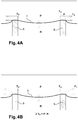
- the geosynthetic 1 is intended to support the embankment 4, placed on the ground 2, liable to present risks of localized collapse due to the opening of cavities or faults 3.
- the fault is represented, but it is obvious that during the construction phase, the fault does not yet exist.
- the geotextile of the invention surmounted by the embankment 4 sags locally directly above said fault, this sag being intended to be visible or in any case detectable. by instrumentation at the level of the geotextile.
- the geotextile of the invention has a particular behavior, illustrated in particular in relation to the curve of the figure 5 .
- the curve which is at a certain level of resistance R1 calculated for the installation and according to the requirements of the specifications of the work allows a relatively substantial deformation of the geosynthetic, which can go from a low value, for example 0.5 to 3% up to higher values (2 to 5, or even 6% if necessary).
- a deformation of the geosynthetic and as a corollary of the embankment which covers it, in order to be detectable, in order to play the role of warning in the event of the occurrence of a collapse or subsidence following the formation of a cavity or fault.
- This deformation is also desired in order to allow tensioning of the geotextile in the case of a work to be carried out using rigid inclusions.
- the curve straightens very strongly in B to react and oppose the deformation of the geosynthetic, and as a corollary to the displacement of the soil or to the subsidence or collapse during the formation of a cavity or to initiate the tensioning geosynthetic on rigid inclusions.
- the method of placing the geotextile of the invention in two stages, the first to ensure the tensioning of the geotextile, and the second to finalize the backfill ensures a greater load transfer on the rigid inclusions, allowing a more economical design of the inclusions: thus, by increasing the authorized spacing between the inclusions (mesh), it is possible to reduce the overall quantity.
- the slope bends (zone C) so as to make visible settlement of the surface of the structure: in this case, which can occur for example in the event of opening of the cavity in several phases, the geosynthetic plays at again its role as a warning device and the deformation visible on the surface indicates the need for repairs to the structure. Nevertheless, the geosynthetic, even deformed, allows an anti-fall safety since it prevents the collapse which would normally result from the opening of the cavity.
- zone C' the slope increases further (zone C') compared to zone B': this case also corresponds to the possibility of opening the cavity in several phases, but assuming this time that the specifications do not authorize only a very low additional settlement: it is understood that in this case, the modulus of the geosynthetic in this third part must be even higher in order to take up significant efforts while limiting the deformation (zone D').
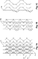
- the Figure 7A thus illustrates a first example of construction of a monodirectional geosynthetic (without wefts) responding to the desired application.
- This is a schematic representation in which a first series of threads 71 are arranged in a rectilinear manner in the production direction (warp).
- a second series of wires 72 is introduced according to a structure imposing on said wires a determined undulation.
- the “undulation” of the threads 72 occurs while an elongation of the geosynthetic is exerted, authorized by deformation of the connecting structure, which consists of threads 73 and 74 themselves at high elongation, and possibly up to the breakup.
- the threads 72 will only begin to intervene from this value. Beyond the latter, there is an addition of the resistances of the wires 71 and 72, and a resulting curve (zone B or B'), whose slope or modulus will be defined by the characteristics of the wires used.
- the threads 72 may only be connected every “n” rows of stitches so as to introduce only a very small offset. So in the figure 7B , the bonding of the yarns 72b can be modified with a bond on the mesh yarn only every four rows allowing a lower shrinkage when this is desired.
- the Fig. 7C also illustrates a different bottom structure variant for binding.
- Other types of bonding and weaves can be considered, the common point always being a controlled curling of the fibers ensuring the second level of resistance and deformation
- the figures 8A and 8B represent other constructions, in which the yarns 82a and 82b evolve with a greater amplitude on suitable bindings, for example in the form of sectional wefts under two needles with chain, double knit or other bindings, precisely authorizing this evolution of on the one hand, and allowing a certain freedom of movement of the corrugated son 82a and 82b, during their tensile stress on the other hand.
- the resulting curve (zone A) with a relatively low slope can then have a longer first part.
- transverse wefts illustrated in broken lines have been introduced, offering the possibility of using only three son guide bars because it is possible in such a case to have only one set of binding son 83b.
- this construction turns out to be more economical.
- a nonwoven, a woven or a veil 86 can be added directly during the manufacturing step.
- the Fig. 8C is another example of construction of the geosynthetic of the invention, in which all the wires or cables are arranged on the same guide line (designated wire guide bar), but with a double positive supply with a different flow rate. This solution is possible when the desired difference or phase shift between the first part of the curve (zone A) and the second part of the curve (zone B) is relatively small.
- the threading of the wires or cables is then carried out with, for example, the repetition of a type 81b wire, then a type 82b wire.
- the choice of the nature of the yarns making up the geosynthetic in question is very precisely adapted to the specific conditions of the structure and the site.
- It can be standard polyester or retracted type with high elongation curve), polyamide, polypropylene or high strength polyethylene but with an elongation at break of around 20%.
- Fibers can also be used, whether synthetic, chemical or even natural, depending on the requirements of the work.
- high modulus yarns 72, 72b, 82a, 82b arranged with overfeed or crimp it is to use high strength or high modulus yarns like HT (high tenacity) polyester, aramid fibers, PVA (polyvinylacetate), glass, carbon, basalt, HT polyethylene (high tenacity), or even fibers such as Vectran ® (aromatic polyester), etc...
- HT high tenacity
- aramid fibers polyvinylacetate
- PVA polyvinylacetate
- glass carbon
- carbon basalt
- HT polyethylene high tenacity
- Vectran ® aromatic polyester
- polypropylene in the position of the yarns 71, 81a or 81b and a high modulus fiber insensitive to an alkaline medium such as PVA for the yarns 72, 72b, 82a or 82b.
- the binding threads can be standard, and typically made of polyester or polyethylene. Indeed, their low resistance allows a fusible effect in phase 1 (zone A) to allow passage to phase 2 (zone B, B').
- the geotextile of the invention can also have a woven structure, and no longer a knitted one.
- the figures 9 and 10 represent two embodiments implementing such a woven structure.
- the figure 10 illustrate another weave, in which we find exactly the same principle but with two different sets of threads in addition to the basic taffeta 100, 101.
- the threads 101 of the base fabric only come into play when they are "unwavy"; they are based on the most efficient material in terms of mechanical properties and act on the second part (zone B) of the geosynthetic's tensile curve.
- the wires 102 and 102' are stressed immediately when the geosynthetic is subjected to traction, that is to say corresponding to zone A of the curve of the figure 5 .
- the yarns 102 and 102' have floats of different lengths, and therefore different embuvages, in addition to the different type of materials constituting them, different slopes of the starting tensile curves are obtained. More specifically, a traction curve with three successive slopes is obtained, as illustrated on the figures 6A and 6B .
- the figures 9B and 10B are schematic representations of the weaves, to program them on the looms.
Landscapes
- Engineering & Computer Science (AREA)
- Mining & Mineral Resources (AREA)
- Life Sciences & Earth Sciences (AREA)
- General Life Sciences & Earth Sciences (AREA)
- Paleontology (AREA)
- Civil Engineering (AREA)
- General Engineering & Computer Science (AREA)
- Structural Engineering (AREA)
- Textile Engineering (AREA)
- Pit Excavations, Shoring, Fill Or Stabilisation Of Slopes (AREA)
- Revetment (AREA)
Claims (8)
- Erdverstärkendes Geotextil mit einer Verformungskurve, deren Steigung das Geotextilmodul darstellt, mit der Verformung in der x-Achse und der aufgebrachten Spannung in der y-Achse, mit mindestens zwei getrennten Dehnungszonen unter Spannung in mindestens einer Richtung, und zwar jeweils:• eine erste Zone (A) mit starker Dehnung für die Verformung des Geokunststoffs zwischen 0 % und einem Grenzwert zwischen 0,5 % und 6 % in mindestens einer Richtung für Zugspannungen von 0 und 10 bis 400 kN/m, die diesem Verformungsgrenzwert entspricht;• eine zweite Dehnungszone (B) über die erste Dehnungszone (A) hinaus, mit einer maximalen Verformung von 2 % bis 20 % in mindestens einer Richtung, für Spannungen zwischen 100 und 3000 kN/m mindestens, die dieser maximalen Verformung entsprechen, gekennzeichnet durch eine Kurvensteigung, die höher ist als die der ersten Dehnungszone (A),der Unterschied der Dehnungszonen ist auf die Natur der Fäden zurückzuführen, aus denen das Geotextil besteht, und/ oder auf die Struktur des Geotextils.
- Erdverstärkendes Geotextil nach Anspruch 1, dadurch gekennzeichnet, dass es aus einer gewirkten Struktur besteht, ausgeführt durch Kettenwirktechnik, die in der Kette eine Reihe rechtwinkliger Fäden (71, 81), enthält und eine oder mehrere Reihen Kettfäden (72, 82), verbunden mit den eventuellen Schusssfäden oder einem eventuellen Trägermaterial über Bindungsfäden, durch die sie eine Amplitudenwelligkeit erhalten können, die gewählt wird entsprechend der gewünschten Welligkeit und gleichzeitig der Bedeutung des Verhaltensgesetzes und insbesondere die Grenzwerte der Verformungszonen, die diese Geotextil erhalten soll.
- Erdverstärkendes Geotextil nach Anspruch 2, dadurch gekennzeichnet, dass das Trägermaterial aus einem Gewebe, einem Vlies, einem Gestrick, einer Folie, einer Membran oder sogar mehreren Materialschichten besteht.
- Erdverstärkendes Geotextil nach Anspruch 1, dadurch gekennzeichnet, dass es aus einem Gewebe besteht, bestehend aus einer Basis mit Leinwandbindung oder Taftbindung, vom Typ Atlas oder Rippen, unter Einlage von Fäden in flottierender Form in Kette oder Schuss, das heißt, die über mehrere Kett- und/ oder Schussfäden hinwegführen, die Menge der übersprungenen Kett- oder Schussfäden bestimmt das Verhalten des Geotextils der Wirkung der sofortigen Zugdehnung.
- Erdverstärkendes Geotextil nach einem der Ansprüche 1 bis 4, dadurch gekennzeichnet, dass die Fäden, aus denen die Struktur besteht, aus Fasern mit hoher Zugfestigkeit bestehen, vorzugsweise ausgewählt aus der Gruppe mit PET, d.h. Polyethylenterephthalat, Polyamid, Polypropylen, Polyethylen, Polyvinylacetat, aromatische Polyester, Aramid, Kohlenstoff, Stahl, Edelstahl, biobasierte Faser, wie Polymilchsäure, Polybutylensuccinat (PBS), sogar natürliche Fasern, wie zum Beispiel Baumwolle, Hanf oder Leinen.
- Erdverstärkendes Geotextil nach einem der Ansprüche 1 bis 5, dadurch gekennzeichnet, dass es kombiniert ist mit einer oder mehreren Materialschichten, vom Typ Gewebe, Vlies oder einem Gewirk, das zusätzlich die Funktionen Drainage, Filterung, Schadstoffrückhaltung, Mischungsvektor, vollständige oder teilweise Abdichtung, Umweltschutzbehandlung erfüllt.
- Erdverstärkendes Geotextil nach einem der Ansprüche 1 bis 6, dadurch gekennzeichnet, dass in der Textilstruktur integriert oder in einem späteren Schritt durch Kleben oder irgendeine andere Befestigungsart hinzugefügt, ein Verfahren zur Messung der Verformung enthalten ist, vom Typ optische Faser mit Bragg-Gitter oder vom Typ Brillouin-Streuung oder ähnliches oder Dehnungsmessstreifen.
- Erdverstärkendes Geotextil nach Anspruch 1, dessen Verformungskurve eine dritten Dehnungszone (C) enthält, jenseits der erwähnten zweiten Dehnungszone, in der das geosynthetische Modul höher oder niedriger, als dass der erwähnten ersten und zweiten Dehnungszone ist.
Applications Claiming Priority (2)
| Application Number | Priority Date | Filing Date | Title |
|---|---|---|---|
| FR1462214A FR3029943B1 (fr) | 2014-12-11 | 2014-12-11 | Geosynthetique de renforcement de sol a comportement multi-module |
| PCT/FR2015/053077 WO2016092167A1 (fr) | 2014-12-11 | 2015-11-16 | Geosynthetique de renforcement de sol a comportement multi-module |
Publications (2)
| Publication Number | Publication Date |
|---|---|
| EP3230509A1 EP3230509A1 (de) | 2017-10-18 |
| EP3230509B1 true EP3230509B1 (de) | 2022-01-12 |
Family
ID=52589589
Family Applications (1)
| Application Number | Title | Priority Date | Filing Date |
|---|---|---|---|
| EP15816813.8A Active EP3230509B1 (de) | 2014-12-11 | 2015-11-16 | Erdverstärkendes multimodul-geotextil |
Country Status (4)
| Country | Link |
|---|---|
| EP (1) | EP3230509B1 (de) |
| FR (1) | FR3029943B1 (de) |
| HU (1) | HUE057836T2 (de) |
| WO (1) | WO2016092167A1 (de) |
Families Citing this family (4)
| Publication number | Priority date | Publication date | Assignee | Title |
|---|---|---|---|---|
| CA3065320C (en) | 2017-06-16 | 2023-09-05 | Saint-Gobain Adfors Canada, Ltd. | Sensing textile |
| CN108108507B (zh) * | 2017-08-26 | 2021-03-30 | 中铁二院工程集团有限责任公司 | 一种高强土工布加固铁路岩溶路基的设计方法 |
| FR3080864B1 (fr) * | 2018-05-03 | 2020-05-01 | Texinov | Produit geotextile ou de construction de renfort instrumente |
| CN109024666B (zh) * | 2018-09-11 | 2024-03-15 | 中铁磁浮交通投资建设有限公司 | 一种具有防治和预警岩溶塌陷的墙网组合结构和施工方法 |
Family Cites Families (6)
| Publication number | Priority date | Publication date | Assignee | Title |
|---|---|---|---|---|
| US3855678A (en) * | 1968-11-21 | 1974-12-24 | Owens Corning Fiberglass Corp | Method of making woven sheet for rubber reinforcement |
| GB2017162A (en) * | 1978-03-22 | 1979-10-03 | Finquattro Spa | Loom for Producing Fancy Yarns |
| JP3020863B2 (ja) * | 1996-02-23 | 2000-03-15 | 栄レース株式会社 | レース編物の編成方法及びレース編物 |
| FR2767344B1 (fr) | 1997-08-13 | 1999-11-05 | Bidim Geosynthetics Sa | Geosynthetique pour dispositif de renforcement de sols a risques d'effondrement |
| DE102006023588B3 (de) * | 2006-05-17 | 2007-09-27 | Sächsisches Textilforschungsinstitut eV | Verwendung eines multifunktionalen, sensorbasierten Geotextilsystems zur Deichertüchtigung, für räumlich ausgedehntes Deichmonitoring sowie für die Gefahrenerkennung im Hochwasserfall |
| FR2932820B1 (fr) | 2008-06-23 | 2012-11-16 | Mdb Texinov Sa | Nappe et grille de renfort avec introduction de fibres minerales pour les ouvrages de genie civil. |
-
2014
- 2014-12-11 FR FR1462214A patent/FR3029943B1/fr active Active
-
2015
- 2015-11-16 HU HUE15816813A patent/HUE057836T2/hu unknown
- 2015-11-16 EP EP15816813.8A patent/EP3230509B1/de active Active
- 2015-11-16 WO PCT/FR2015/053077 patent/WO2016092167A1/fr active Application Filing
Also Published As
| Publication number | Publication date |
|---|---|
| FR3029943A1 (fr) | 2016-06-17 |
| EP3230509A1 (de) | 2017-10-18 |
| WO2016092167A1 (fr) | 2016-06-16 |
| FR3029943B1 (fr) | 2016-12-30 |
| HUE057836T2 (hu) | 2022-06-28 |
Similar Documents
| Publication | Publication Date | Title |
|---|---|---|
| EP3230509B1 (de) | Erdverstärkendes multimodul-geotextil | |
| EP3259391A2 (de) | Geotextil zur verstärkung, zur bekämpfung von erosion und zur unterstützung der rekultivierung | |
| CA3075033C (en) | Geocell for moderate and low load applications | |
| CA2657712C (fr) | Dispositif, systeme et procede de detection et de localisation de dysfonctionnement dans un ouvrage hydraulique, ainsi qu'un ouvrage hydraulique equipe de ce dispositif | |
| EP2304089B1 (de) | Tuch und verstärkungsnetz mit einsatz von mineralfasern für zivile technische arbeiten | |
| EP2079864B1 (de) | Verbundgeotextil für hoch- und tiefbau | |
| CA2828332A1 (fr) | Armature de renfort d'elements a matrice minerale | |
| EP0897035B1 (de) | Geosynthetische Verstärkungsschicht für setzungsgefährdetes Erdreich | |
| EP2912230B1 (de) | Struktur mit geotextil | |
| KR101186511B1 (ko) | 아스팔트 보강용 텍스타일 지오그리드의 제조방법, 이로부터 형성된 텍스타일 지오그리드 및 이를 이용한 아스팔트 포장방법 | |
| JP5808002B2 (ja) | 主として瓦礫を用いたふとん篭 | |
| JP2013249576A (ja) | 土木用シート | |
| EP2155944B1 (de) | Struktur aus gewirktem stoff auf basaltbasis | |
| EP2004917A1 (de) | Geotextilverstärkungsprodukt mit befestigungselement | |
| KR102494814B1 (ko) | 스트랜드, 로프 및 보행매트 | |
| FR3080864A1 (fr) | Produit geotextile ou de construction de renfort instrumente | |
| Pritchard et al. | A more sustainable solution to geosynthetic products for short-term reinforcing applications | |
| EP4347935A1 (de) | Geosynthetisches material aus einer gestrickten textilstruktur und verfahren zu seiner herstellung | |
| JP3616772B2 (ja) | ジオグリッド、及びそれを用いた盛土の補強方法 | |
| WO2021254814A1 (fr) | Coffrage à ductilité renforcée avec cage d'armatures tridimensionnelle repliable. | |
| Pritchard et al. | International SEEDS Conference: Engineering Design for Society | |
| Das et al. | Tear Propagation of Spun-bonded Nonwoven Geotextiles at Repeated Bursting Pressure Cycle | |
| Koerner et al. | ‘Creep and relaxation of geotextile fabrics’ by G. den Hoedt: Reply to the Discussions of Robert M. Koerner and Gregory N. Richardson, and NE Wrigley and DI Bush, by G. den Hoedt (Enka Research Institute, Velperweg 76, Postbus 60, 6800 AB Arnhem, The Netherlands) | |
| FR2824570A3 (fr) | Protection vis a vis de l'incendie par des blocs de beton ancres des ouvrages de terres renforces par des geotextiles ou produits assimiles | |
| Zannoni | Criteria for the choice of geosynthetics in soil reinforcement: geosynthetics |
Legal Events
| Date | Code | Title | Description |
|---|---|---|---|
| STAA | Information on the status of an ep patent application or granted ep patent |
Free format text: STATUS: THE INTERNATIONAL PUBLICATION HAS BEEN MADE |
|
| PUAI | Public reference made under article 153(3) epc to a published international application that has entered the european phase |
Free format text: ORIGINAL CODE: 0009012 |
|
| STAA | Information on the status of an ep patent application or granted ep patent |
Free format text: STATUS: REQUEST FOR EXAMINATION WAS MADE |
|
| 17P | Request for examination filed |
Effective date: 20170522 |
|
| AK | Designated contracting states |
Kind code of ref document: A1 Designated state(s): AL AT BE BG CH CY CZ DE DK EE ES FI FR GB GR HR HU IE IS IT LI LT LU LV MC MK MT NL NO PL PT RO RS SE SI SK SM TR |
|
| AX | Request for extension of the european patent |
Extension state: BA ME |
|
| DAV | Request for validation of the european patent (deleted) | ||
| DAX | Request for extension of the european patent (deleted) | ||
| STAA | Information on the status of an ep patent application or granted ep patent |
Free format text: STATUS: EXAMINATION IS IN PROGRESS |
|
| 17Q | First examination report despatched |
Effective date: 20210406 |
|
| GRAP | Despatch of communication of intention to grant a patent |
Free format text: ORIGINAL CODE: EPIDOSNIGR1 |
|
| STAA | Information on the status of an ep patent application or granted ep patent |
Free format text: STATUS: GRANT OF PATENT IS INTENDED |
|
| GRAS | Grant fee paid |
Free format text: ORIGINAL CODE: EPIDOSNIGR3 |
|
| GRAA | (expected) grant |
Free format text: ORIGINAL CODE: 0009210 |
|
| STAA | Information on the status of an ep patent application or granted ep patent |
Free format text: STATUS: THE PATENT HAS BEEN GRANTED |
|
| INTG | Intention to grant announced |
Effective date: 20211119 |
|
| AK | Designated contracting states |
Kind code of ref document: B1 Designated state(s): AL AT BE BG CH CY CZ DE DK EE ES FI FR GB GR HR HU IE IS IT LI LT LU LV MC MK MT NL NO PL PT RO RS SE SI SK SM TR |
|
| REG | Reference to a national code |
Ref country code: GB Ref legal event code: FG4D Free format text: NOT ENGLISH |
|
| REG | Reference to a national code |
Ref country code: CH Ref legal event code: EP |
|
| REG | Reference to a national code |
Ref country code: DE Ref legal event code: R096 Ref document number: 602015076446 Country of ref document: DE |
|
| REG | Reference to a national code |
Ref country code: IE Ref legal event code: FG4D Free format text: LANGUAGE OF EP DOCUMENT: FRENCH |
|
| REG | Reference to a national code |
Ref country code: AT Ref legal event code: REF Ref document number: 1462452 Country of ref document: AT Kind code of ref document: T Effective date: 20220215 |
|
| REG | Reference to a national code |
Ref country code: DE Ref legal event code: R081 Ref document number: 602015076446 Country of ref document: DE Owner name: AFITEX INTERNATIONAL, FR Free format text: FORMER OWNERS: DELTAVAL, LYON, FR; TEXINOV, SAINT DIDIER DE LA TOUR, FR |
|
| REG | Reference to a national code |
Ref country code: NL Ref legal event code: FP |
|
| RAP2 | Party data changed (patent owner data changed or rights of a patent transferred) |
Owner name: AFITEX INTERNATIONAL |
|
| REG | Reference to a national code |
Ref country code: BE Ref legal event code: PD Owner name: AFITEX INTERNATIONAL; FR Free format text: DETAILS ASSIGNMENT: CHANGE OF OWNER(S), ASSIGNMENT; FORMER OWNER NAME: DELTAVAL Effective date: 20220309 |
|
| REG | Reference to a national code |
Ref country code: NL Ref legal event code: PD Owner name: AFITEX INTERNATIONAL; FR Free format text: DETAILS ASSIGNMENT: CHANGE OF OWNER(S), ASSIGNMENT; FORMER OWNER NAME: TEXINOV Effective date: 20220309 |
|
| REG | Reference to a national code |
Ref country code: LT Ref legal event code: MG9D |
|
| REG | Reference to a national code |
Ref country code: BE Ref legal event code: PD Owner name: AFITEX INTERNATIONAL; FR Free format text: DETAILS ASSIGNMENT: CHANGE OF OWNER(S), ASSIGNMENT; FORMER OWNER NAME: DELTAVAL Effective date: 20220328 |
|
| REG | Reference to a national code |
Ref country code: GB Ref legal event code: 732E Free format text: REGISTERED BETWEEN 20220505 AND 20220512 |
|
| REG | Reference to a national code |
Ref country code: AT Ref legal event code: MK05 Ref document number: 1462452 Country of ref document: AT Kind code of ref document: T Effective date: 20220112 |
|
| REG | Reference to a national code |
Ref country code: HU Ref legal event code: AG4A Ref document number: E057836 Country of ref document: HU |
|
| PG25 | Lapsed in a contracting state [announced via postgrant information from national office to epo] |
Ref country code: SE Free format text: LAPSE BECAUSE OF FAILURE TO SUBMIT A TRANSLATION OF THE DESCRIPTION OR TO PAY THE FEE WITHIN THE PRESCRIBED TIME-LIMIT Effective date: 20220112 Ref country code: RS Free format text: LAPSE BECAUSE OF FAILURE TO SUBMIT A TRANSLATION OF THE DESCRIPTION OR TO PAY THE FEE WITHIN THE PRESCRIBED TIME-LIMIT Effective date: 20220112 Ref country code: PT Free format text: LAPSE BECAUSE OF FAILURE TO SUBMIT A TRANSLATION OF THE DESCRIPTION OR TO PAY THE FEE WITHIN THE PRESCRIBED TIME-LIMIT Effective date: 20220512 Ref country code: NO Free format text: LAPSE BECAUSE OF FAILURE TO SUBMIT A TRANSLATION OF THE DESCRIPTION OR TO PAY THE FEE WITHIN THE PRESCRIBED TIME-LIMIT Effective date: 20220412 Ref country code: LT Free format text: LAPSE BECAUSE OF FAILURE TO SUBMIT A TRANSLATION OF THE DESCRIPTION OR TO PAY THE FEE WITHIN THE PRESCRIBED TIME-LIMIT Effective date: 20220112 Ref country code: HR Free format text: LAPSE BECAUSE OF FAILURE TO SUBMIT A TRANSLATION OF THE DESCRIPTION OR TO PAY THE FEE WITHIN THE PRESCRIBED TIME-LIMIT Effective date: 20220112 Ref country code: ES Free format text: LAPSE BECAUSE OF FAILURE TO SUBMIT A TRANSLATION OF THE DESCRIPTION OR TO PAY THE FEE WITHIN THE PRESCRIBED TIME-LIMIT Effective date: 20220112 Ref country code: BG Free format text: LAPSE BECAUSE OF FAILURE TO SUBMIT A TRANSLATION OF THE DESCRIPTION OR TO PAY THE FEE WITHIN THE PRESCRIBED TIME-LIMIT Effective date: 20220412 |
|
| PG25 | Lapsed in a contracting state [announced via postgrant information from national office to epo] |
Ref country code: PL Free format text: LAPSE BECAUSE OF FAILURE TO SUBMIT A TRANSLATION OF THE DESCRIPTION OR TO PAY THE FEE WITHIN THE PRESCRIBED TIME-LIMIT Effective date: 20220112 Ref country code: LV Free format text: LAPSE BECAUSE OF FAILURE TO SUBMIT A TRANSLATION OF THE DESCRIPTION OR TO PAY THE FEE WITHIN THE PRESCRIBED TIME-LIMIT Effective date: 20220112 Ref country code: GR Free format text: LAPSE BECAUSE OF FAILURE TO SUBMIT A TRANSLATION OF THE DESCRIPTION OR TO PAY THE FEE WITHIN THE PRESCRIBED TIME-LIMIT Effective date: 20220413 Ref country code: FI Free format text: LAPSE BECAUSE OF FAILURE TO SUBMIT A TRANSLATION OF THE DESCRIPTION OR TO PAY THE FEE WITHIN THE PRESCRIBED TIME-LIMIT Effective date: 20220112 Ref country code: AT Free format text: LAPSE BECAUSE OF FAILURE TO SUBMIT A TRANSLATION OF THE DESCRIPTION OR TO PAY THE FEE WITHIN THE PRESCRIBED TIME-LIMIT Effective date: 20220112 |
|
| PG25 | Lapsed in a contracting state [announced via postgrant information from national office to epo] |
Ref country code: IS Free format text: LAPSE BECAUSE OF FAILURE TO SUBMIT A TRANSLATION OF THE DESCRIPTION OR TO PAY THE FEE WITHIN THE PRESCRIBED TIME-LIMIT Effective date: 20220512 |
|
| REG | Reference to a national code |
Ref country code: DE Ref legal event code: R097 Ref document number: 602015076446 Country of ref document: DE |
|
| PG25 | Lapsed in a contracting state [announced via postgrant information from national office to epo] |
Ref country code: SM Free format text: LAPSE BECAUSE OF FAILURE TO SUBMIT A TRANSLATION OF THE DESCRIPTION OR TO PAY THE FEE WITHIN THE PRESCRIBED TIME-LIMIT Effective date: 20220112 Ref country code: SK Free format text: LAPSE BECAUSE OF FAILURE TO SUBMIT A TRANSLATION OF THE DESCRIPTION OR TO PAY THE FEE WITHIN THE PRESCRIBED TIME-LIMIT Effective date: 20220112 Ref country code: RO Free format text: LAPSE BECAUSE OF FAILURE TO SUBMIT A TRANSLATION OF THE DESCRIPTION OR TO PAY THE FEE WITHIN THE PRESCRIBED TIME-LIMIT Effective date: 20220112 Ref country code: EE Free format text: LAPSE BECAUSE OF FAILURE TO SUBMIT A TRANSLATION OF THE DESCRIPTION OR TO PAY THE FEE WITHIN THE PRESCRIBED TIME-LIMIT Effective date: 20220112 Ref country code: DK Free format text: LAPSE BECAUSE OF FAILURE TO SUBMIT A TRANSLATION OF THE DESCRIPTION OR TO PAY THE FEE WITHIN THE PRESCRIBED TIME-LIMIT Effective date: 20220112 Ref country code: CZ Free format text: LAPSE BECAUSE OF FAILURE TO SUBMIT A TRANSLATION OF THE DESCRIPTION OR TO PAY THE FEE WITHIN THE PRESCRIBED TIME-LIMIT Effective date: 20220112 |
|
| PLBE | No opposition filed within time limit |
Free format text: ORIGINAL CODE: 0009261 |
|
| STAA | Information on the status of an ep patent application or granted ep patent |
Free format text: STATUS: NO OPPOSITION FILED WITHIN TIME LIMIT |
|
| PG25 | Lapsed in a contracting state [announced via postgrant information from national office to epo] |
Ref country code: AL Free format text: LAPSE BECAUSE OF FAILURE TO SUBMIT A TRANSLATION OF THE DESCRIPTION OR TO PAY THE FEE WITHIN THE PRESCRIBED TIME-LIMIT Effective date: 20220112 |
|
| 26N | No opposition filed |
Effective date: 20221013 |
|
| PG25 | Lapsed in a contracting state [announced via postgrant information from national office to epo] |
Ref country code: SI Free format text: LAPSE BECAUSE OF FAILURE TO SUBMIT A TRANSLATION OF THE DESCRIPTION OR TO PAY THE FEE WITHIN THE PRESCRIBED TIME-LIMIT Effective date: 20220112 |
|
| PG25 | Lapsed in a contracting state [announced via postgrant information from national office to epo] |
Ref country code: MC Free format text: LAPSE BECAUSE OF FAILURE TO SUBMIT A TRANSLATION OF THE DESCRIPTION OR TO PAY THE FEE WITHIN THE PRESCRIBED TIME-LIMIT Effective date: 20220112 |
|
| P01 | Opt-out of the competence of the unified patent court (upc) registered |
Effective date: 20230527 |
|
| PGFP | Annual fee paid to national office [announced via postgrant information from national office to epo] |
Ref country code: NL Payment date: 20231120 Year of fee payment: 9 Ref country code: LU Payment date: 20231120 Year of fee payment: 9 |
|
| PGFP | Annual fee paid to national office [announced via postgrant information from national office to epo] |
Ref country code: GB Payment date: 20231123 Year of fee payment: 9 |
|
| PGFP | Annual fee paid to national office [announced via postgrant information from national office to epo] |
Ref country code: IT Payment date: 20231124 Year of fee payment: 9 Ref country code: IE Payment date: 20231121 Year of fee payment: 9 Ref country code: HU Payment date: 20231122 Year of fee payment: 9 Ref country code: FR Payment date: 20231106 Year of fee payment: 9 Ref country code: DE Payment date: 20231121 Year of fee payment: 9 Ref country code: CH Payment date: 20231201 Year of fee payment: 9 |
|
| PGFP | Annual fee paid to national office [announced via postgrant information from national office to epo] |
Ref country code: BE Payment date: 20231120 Year of fee payment: 9 |
|
| PG25 | Lapsed in a contracting state [announced via postgrant information from national office to epo] |
Ref country code: CY Free format text: LAPSE BECAUSE OF FAILURE TO SUBMIT A TRANSLATION OF THE DESCRIPTION OR TO PAY THE FEE WITHIN THE PRESCRIBED TIME-LIMIT Effective date: 20220112 |
|
| PG25 | Lapsed in a contracting state [announced via postgrant information from national office to epo] |
Ref country code: MK Free format text: LAPSE BECAUSE OF FAILURE TO SUBMIT A TRANSLATION OF THE DESCRIPTION OR TO PAY THE FEE WITHIN THE PRESCRIBED TIME-LIMIT Effective date: 20220112 |
|
| PG25 | Lapsed in a contracting state [announced via postgrant information from national office to epo] |
Ref country code: TR Free format text: LAPSE BECAUSE OF FAILURE TO SUBMIT A TRANSLATION OF THE DESCRIPTION OR TO PAY THE FEE WITHIN THE PRESCRIBED TIME-LIMIT Effective date: 20220112 |