EP3230176B1 - Dispositif de verrouillage pour un conteneur et procédé de fabrication d'un conteneur à déchets - Google Patents
Dispositif de verrouillage pour un conteneur et procédé de fabrication d'un conteneur à déchets Download PDFInfo
- Publication number
- EP3230176B1 EP3230176B1 EP15819953.9A EP15819953A EP3230176B1 EP 3230176 B1 EP3230176 B1 EP 3230176B1 EP 15819953 A EP15819953 A EP 15819953A EP 3230176 B1 EP3230176 B1 EP 3230176B1
- Authority
- EP
- European Patent Office
- Prior art keywords
- locking
- paddle
- container
- locking device
- locking block
- Prior art date
- Legal status (The legal status is an assumption and is not a legal conclusion. Google has not performed a legal analysis and makes no representation as to the accuracy of the status listed.)
- Active
Links
- 239000002699 waste material Substances 0.000 title claims description 12
- 238000000034 method Methods 0.000 title claims description 11
- 230000000903 blocking effect Effects 0.000 claims description 32
- 239000000463 material Substances 0.000 description 9
- 230000005484 gravity Effects 0.000 description 6
- 238000010168 coupling process Methods 0.000 description 5
- 230000008878 coupling Effects 0.000 description 4
- 238000005859 coupling reaction Methods 0.000 description 4
- 241001465754 Metazoa Species 0.000 description 3
- 230000007246 mechanism Effects 0.000 description 3
- 239000002184 metal Substances 0.000 description 3
- 239000000853 adhesive Substances 0.000 description 2
- 230000001070 adhesive effect Effects 0.000 description 2
- 230000004048 modification Effects 0.000 description 2
- 238000012986 modification Methods 0.000 description 2
- 239000010813 municipal solid waste Substances 0.000 description 2
- 230000008569 process Effects 0.000 description 2
- 238000004064 recycling Methods 0.000 description 2
- -1 recycling items Substances 0.000 description 2
- 239000010925 yard waste Substances 0.000 description 2
- 238000011109 contamination Methods 0.000 description 1
- 230000006866 deterioration Effects 0.000 description 1
- 239000000696 magnetic material Substances 0.000 description 1
- 230000000717 retained effect Effects 0.000 description 1
- 239000000725 suspension Substances 0.000 description 1
- 238000003466 welding Methods 0.000 description 1
Images


Classifications
-
- B—PERFORMING OPERATIONS; TRANSPORTING
- B65—CONVEYING; PACKING; STORING; HANDLING THIN OR FILAMENTARY MATERIAL
- B65F—GATHERING OR REMOVAL OF DOMESTIC OR LIKE REFUSE
- B65F1/00—Refuse receptacles; Accessories therefor
- B65F1/14—Other constructional features; Accessories
- B65F1/16—Lids or covers
- B65F1/1615—Lids or covers with means for locking, fastening or permanently closing thereof
-
- B—PERFORMING OPERATIONS; TRANSPORTING
- B65—CONVEYING; PACKING; STORING; HANDLING THIN OR FILAMENTARY MATERIAL
- B65F—GATHERING OR REMOVAL OF DOMESTIC OR LIKE REFUSE
- B65F1/00—Refuse receptacles; Accessories therefor
- B65F1/14—Other constructional features; Accessories
- B65F1/16—Lids or covers
- B65F1/1646—Lids or covers provided with means for mounting on receptacles, e.g. hinges
-
- E—FIXED CONSTRUCTIONS
- E05—LOCKS; KEYS; WINDOW OR DOOR FITTINGS; SAFES
- E05B—LOCKS; ACCESSORIES THEREFOR; HANDCUFFS
- E05B15/00—Other details of locks; Parts for engagement by bolts of fastening devices
- E05B15/0086—Toggle levers
-
- E—FIXED CONSTRUCTIONS
- E05—LOCKS; KEYS; WINDOW OR DOOR FITTINGS; SAFES
- E05B—LOCKS; ACCESSORIES THEREFOR; HANDCUFFS
- E05B15/00—Other details of locks; Parts for engagement by bolts of fastening devices
- E05B15/0093—Weight arrangements in locks; gravity activated lock parts
-
- E—FIXED CONSTRUCTIONS
- E05—LOCKS; KEYS; WINDOW OR DOOR FITTINGS; SAFES
- E05B—LOCKS; ACCESSORIES THEREFOR; HANDCUFFS
- E05B17/00—Accessories in connection with locks
- E05B17/20—Means independent of the locking mechanism for preventing unauthorised opening, e.g. for securing the bolt in the fastening position
- E05B17/2007—Securing, deadlocking or "dogging" the bolt in the fastening position
- E05B17/203—Securing, deadlocking or "dogging" the bolt in the fastening position not following the movement of the bolt
- E05B17/2034—Securing, deadlocking or "dogging" the bolt in the fastening position not following the movement of the bolt moving pivotally or rotatively
-
- E—FIXED CONSTRUCTIONS
- E05—LOCKS; KEYS; WINDOW OR DOOR FITTINGS; SAFES
- E05B—LOCKS; ACCESSORIES THEREFOR; HANDCUFFS
- E05B47/00—Operating or controlling locks or other fastening devices by electric or magnetic means
- E05B47/0038—Operating or controlling locks or other fastening devices by electric or magnetic means using permanent magnets
-
- E—FIXED CONSTRUCTIONS
- E05—LOCKS; KEYS; WINDOW OR DOOR FITTINGS; SAFES
- E05B—LOCKS; ACCESSORIES THEREFOR; HANDCUFFS
- E05B65/00—Locks or fastenings for special use
- E05B65/006—Locks or fastenings for special use for covers or panels
-
- E—FIXED CONSTRUCTIONS
- E05—LOCKS; KEYS; WINDOW OR DOOR FITTINGS; SAFES
- E05C—BOLTS OR FASTENING DEVICES FOR WINGS, SPECIALLY FOR DOORS OR WINDOWS
- E05C19/00—Other devices specially designed for securing wings, e.g. with suction cups
- E05C19/10—Hook fastenings; Fastenings in which a link engages a fixed hook-like member
- E05C19/12—Hook fastenings; Fastenings in which a link engages a fixed hook-like member pivotally mounted around an axis
- E05C19/14—Hook fastenings; Fastenings in which a link engages a fixed hook-like member pivotally mounted around an axis with toggle action
-
- E—FIXED CONSTRUCTIONS
- E05—LOCKS; KEYS; WINDOW OR DOOR FITTINGS; SAFES
- E05C—BOLTS OR FASTENING DEVICES FOR WINGS, SPECIALLY FOR DOORS OR WINDOWS
- E05C21/00—Arrangements or combinations of wing fastening, securing, or holding devices, not covered by a single preceding main group; Locking kits
- E05C21/005—Provisional arrangements between door and frame for holding vehicle doors closed or partially open during manufacturing or maintenance
-
- E—FIXED CONSTRUCTIONS
- E05—LOCKS; KEYS; WINDOW OR DOOR FITTINGS; SAFES
- E05C—BOLTS OR FASTENING DEVICES FOR WINGS, SPECIALLY FOR DOORS OR WINDOWS
- E05C3/00—Fastening devices with bolts moving pivotally or rotatively
- E05C3/12—Fastening devices with bolts moving pivotally or rotatively with latching action
- E05C3/16—Fastening devices with bolts moving pivotally or rotatively with latching action with operating handle or equivalent member moving otherwise than rigidly with the latch
-
- B—PERFORMING OPERATIONS; TRANSPORTING
- B65—CONVEYING; PACKING; STORING; HANDLING THIN OR FILAMENTARY MATERIAL
- B65F—GATHERING OR REMOVAL OF DOMESTIC OR LIKE REFUSE
- B65F2210/00—Equipment of refuse receptacles
- B65F2210/148—Locking means
-
- E—FIXED CONSTRUCTIONS
- E05—LOCKS; KEYS; WINDOW OR DOOR FITTINGS; SAFES
- E05B—LOCKS; ACCESSORIES THEREFOR; HANDCUFFS
- E05B65/00—Locks or fastenings for special use
- E05B65/52—Other locks for chests, boxes, trunks, baskets, travelling bags, or the like
- E05B65/5292—Gravity - or orientation sensitive mechanisms, e.g. to prevent opening when wrongside-up
Definitions
- the present invention generally relates to locking devices for a container, e.g. a waste container.
- Household refuse such as trash, recycling items, and/or yard waste can be deposited in a container.
- Such containers can include a lid for concealing the household refuse collected therein, as well as to prevent wild animals or people from accessing the household refuse and also protecting the content of the containers from the elements.
- the lid can be removably coupled to the container in a friction-fit manner to allow the lid to be easily removed from the container.
- the contents can be undesirably expelled from the container.
- a strap can be coupled to the lid and the container in a snap lock fashion.
- this locking method requires a plurality of steps to secure the strap and the strap can easily become separated from the container.
- Another exemplary locking device includes a metal coil coupled between the lid and the container to provide great tension holding the lid in place.
- the coil can deteriorate due to exposure to the elements.
- Prior art document US 5 419 598 A discloses a locking device comprising a gravity actuated mechanism which allows opening of the container when the container is tilted in a direction, and it does not allow it when the container is upright or tilted in another direction.
- this locking device there is a locking arm coupled to a rotatable shaft, wherein the shaft has a cam which interferes with the locking mechanism.
- the present invention provides a locking device for a container, that keeps the lid of the container closed when the container is knocked over on its side, with a sudden jerking or jarring motion, such as by impact with the ground, to prevent spillage of its contents.
- the locking device allows the lid to open when the container, e.g. a waste container, is tipped over, preferably in a forward direction, by a dumping operation.
- a clocking device which may be mounted on the container. Since the second end of the paddle is detachably mounted to a mounting surface, by magnetic attraction, a sudden jerking or jarring motion, such as by impact with the ground, causes the second end to detach from the mounting surface to block the locking block from moving from the locked position to the opened position. On the other hand, if the container is tipped over without impact, e.g. by being intentionally laid over by a user, the second end of the paddle remains attached to the mounting surface, which allows the locking block to be moved to an opened position. Essentially, the paddle provides a mechanical sensor that detects whether the container has been unintendedly tipped over or whether it is being intentionally laid over, such as for dumping.
- the locking device includes an arm configured to be removably coupled to a surface of the container.
- the arm is coupled to a rotatable shaft that extends through a housing of the locking device.
- a cam coupled to the rotatable shaft is disposed within the housing of the locking device.
- the cam is configured to rotate with the shaft.
- a first paddle and a second paddle are pivotably suspended from a paddle shaft within the housing of the locking device.
- a paddle actuation device has a lever extending outside the housing of the locking device, a shaft extending through an opening in a sidewall of the housing of the locking device, and a planar member coupled to the shaft.
- the planar member of the paddle actuation device is configured to actuate the first paddle when a force is applied to the lever of the paddle actuation device.
- a locking block has a channel, a first sloped surface associated with the first paddle, a second sloped surface associated with the second paddle, and a blocking device compartment.
- a magnetic device is mounted on a surface of the channel of the locking block opposite the second sloped surface.
- a blocking device has a cavity formed in a lower surface of the blocking device. The cavity is configured to receive a stoppage device. The blocking device is mounted to an inner surface of the housing of the locking device.
- the container 10 may be a refuse container such as a household refuse container for various items including trash, recycling, and/or yard waste. However, container 10 may be used to accommodate any type of article. Container 10 may have any shape. For example, container 10 may be annular or polygonal. In addition, container 10 can be made of various materials such as plastic, metal, or a combination thereof.
- Container 10 includes a lid 12 and a containment body 14.
- the containment body 14 defines an interior volume for holding, e.g., waste.
- the lid 12 can be separate from the containment body 14 or can be pivotally mounted to the containment body though coupling 16, such as a lid hinge.
- the containment body 14 may include a plurality of side walls 18.
- the lid 12 and the containment body 14 of container 10 may be made of the same or different materials.
- wheels (not shown) may be coupled to the containment body to aid in transport of the container.
- a locking device 20 is coupled to a portion of the container 10.
- locking device 20 may be mounted to a side wall 18 of the container 10 (preferably a front side wall opposite to the side wall where the coupling 16 is attached) where the locking arm 22 of the locking device 20 is removably coupled to a top surface of the lid 12 of the container 10.
- the locking device 20 can alternatively be mounted on the lid 12, where the locking arm 22 is removably coupled to a portion of a side wall 18 of the containment body 14.
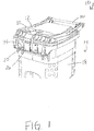
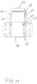
- the locking device 20 When in a locked position, e.g. as illustrated in FIG. 1 , the locking device 20 is configured to prevent access to the inside of the containment body 14. In an exemplary embodiment, the locking device 20 prevents the lid 12 from separating from the containment body 14 of the container and/or prevents the contents of the container 10 from being removed or expelled from the containment body 14. As best illustrated in FIG. 1 , the locking device 20 is mounted to a side wall 18 of the container 10 using a mounting plate 24. The mounting plate 24 may be coupled to the container 10 using various methods such as adhesive, mechanical fasteners, such as screws, bolts, or the like. While the locking device 20 is illustrated as being formed separate from the container 10, one of ordinary skill in the art would appreciate that the locking device 20 may be manufactured integral with the container 10.
- Locking device 20 includes a locking arm 22, a locking device housing 26, a rotatable shaft 28, a cam 30, a first paddle 32, a second paddle 34, a paddle actuation device 36, a locking block 38, a magnetic device 40, and a blocking device 96, as illustrated in FIGS. 2-8 .
- the locking arm 22 comprises a planar portion 44 configured to contact an upper surface of the lid 12. While the locking arm 22 may have a shape as illustrated in FIGS. 1-8 , one of ordinary skill in the art would recognize that the locking arm 22 can have any shape such that when the locking device 20 is in a locked position, the arm 22 prevents the lid 12 from separating from containment body 14, preferably from lifting upwardly and away from the containment body 14.
- the locking arm 22 is a single unarticulated [?] structure, as best illustrated in FIGS. 2-3 , where the planar portion 44 is integral with the portion of the locking arm 22 that is coupled to the rotatable shaft 28, such that when the locking arm 22 rotates around the axis of the rotatable shaft 28, the planar portion 44 has the same moment of inertia as the rest of the locking arm 22.
- the locking arm 22 is coupled to the rotatable shaft 28.
- the locking arm 22 can be permanently coupled to the shaft 28 such that when the locking arm 22 is actuated, the shaft 28 rotates about an axis.
- the locking arm 22 may be integrally formed with the rotatable shaft 28.
- the rotatable shaft 28 extends through an opening 46 formed in a sidewall 48 of the locking device housing 26.
- a cam 30 is fixedly coupled to the rotatable shaft 28 using any of various coupling techniques such as welding, adhesive, mechanical fasteners, etc.
- the cam 30 preferably is a cylinder having a center axis that is parallel to the center axis of the rotatable shaft 28, and coupled to the rotatable shaft 28, such that when the rotatable shaft 28 rotates on its center axis, the center axis of the cam 30 moves in an arc around the rotatable shaft 28.
- the cam 30 may be contained entirely within the locking device housing 26, so that the cam 30 does not extend through the sidewalls 48 of the locking device housing 26.
- the cam 30 contacts a lower surface 50 of the locking block 38 where the position of the cam 30 is based on the position of the arm 22 of the locking device 20.
- the cam 30 when the locking arm 22 is in the locked position, the cam 30 is in a lateral position with respect to the rotatable shaft 28, as best illustrated in FIGS. 6-8 .
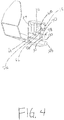
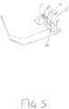
- the cam 30 When the locking arm 22 is actuated and spaced away from the lid 12 of the container 10 (an opened position of the locking arm 22), the cam 30 is rotated into a vertical position such that the cam 30 is above the rotatable shaft 28, as best illustrated in FIGS. 4-5 .
- the cam 30 can be coupled to the rotatable shaft 28 such that when the locking arm 22 is in the locked position, only the rotatable shaft 28 is in contact with the lower surface 50 of the locking block 38; and as the locking arm 22 is actuated, the cam 30 can rotate thereby coming into contact with the lower surface 50 of the locking block 38.
- a bias force may be applied to the locking block 38 such that the lower surface 50 of the locking block 38 does not touch the rotatable shaft 28.
- At least one paddle may be mounted within the locking device housing 26.
- a first paddle 32 and a second paddle 34 are rotatably suspended from a paddle shaft 52, such that the first and second paddles 32, 34 may pivot around the paddle shaft 52.
- the paddles 32,34 are preferably disposed adjacent to each other and extend in parallel.
- Each of the paddles 32, 34 has a sleeve portion 54 and a planar portion 56.
- the sleeve portion 54 surrounds the paddle shaft 52 and the planar portion 56 extends from the sleeve portion 54 such that the planar portion 56 can freely swing about the paddle shaft 52.
- the paddles 32, 34 may be made of various materials such as plastic, metal, etc, and may be made of the same material or different material. While two paddles 32, 34 are illustrated, only one paddle may be used. For example, only the first paddle 32 is used, while the second paddle is not; or conversely, only the second paddle is used.
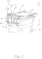
- a paddle actuation device 36 ( FIG. 7 ) is configured to actuate the first paddle 32 from the suspended position such that the locking arm 22 can be actuated after a force is applied to the paddle actuation device 36.
- the paddle actuation device 36 includes a lever 60, a planar member 62, and a shaft 64 coupled between the lever 60 and the planar member 62.
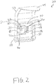
- the lever 60 extends outside the housing 26 of the locking device 20 (as best shown in FIG. 3 ), such that a user can interact with the paddle actuation device 36.
- the shaft 64 extends through an opening formed in a sidewall 48 of the locking device housing 26 and translates the force applied on the lever 60 to the planar member 62.
- the planar member 62 is arranged at an angle with respect to the first paddle 32 as best illustrated in FIGS. 2 and 5-8 .
- an opening (not illustrated) is formed in the lever 60 of the paddle actuation device 36 where a portion of a padlock or other locking mechanism is coupled to the container 10 through the opening.
- the paddle actuation device 36 is preferably located proximate to the first paddle 32.
- a locking block 38 is configured to prevent the paddles 32, 34 from freely swinging under certain circumstances.
- the locking block 38 includes a channel 66 formed in the length of the block 38, a first sloped surface 70, a second sloped surface 72, and a blocking device compartment 76.
- the depth of the channel 66 is such that the paddles may slide into the channel when the locking block 38 is lifted by the cam 30 when the locking arm 22 is in the opened position (as discussed in further detail below).
- the second paddle 34 may be made of a magnetic material and a magnetic device 40, e.g. as a magnet, may be mounted on an inner surface 68 of the channel 66 of the locking block 38, as best shown in Fig. 8 .
- the magnetic device 40 is mounted on the side of the channel 66 opposite to the side associated with the second sloped surface 72.
- the second paddle 34 is in magnetic contact with the magnetic device 40 unless a force greater than the magnetic force between the second paddle 34 and the magnetic device 40 acts upon the locking device 20.
- the magnitude of the magnetic force between the second paddle 34 and the magnetic device 40 may be modified based on the type and/or size of the selected magnetic device 40.
- a magnetic device 40 having a smaller surface area and/or a material having weaker magnetic properties is selected to create a small magnetic force between the paddle 34 and the magnetic device 40. If it is desired that the paddle 34 and the magnetic device 40 separate only when a large force acts upon the container 10, a magnetic device 40 having a larger surface area and/or a material having stronger magnetic properties is selected to create a large magnetic force between the paddle 34 and the magnetic device 40.
- the first sloped surface 70 and the second sloped surface 72 are formed in an upper surface of the locking block 38, as best shown in Figs. 7-8 .
- the first sloped surface 70 is associated with the first paddle 32; and the second sloped surface 72 is associated with the second paddle 34.
- the first paddle 32 contacts the first sloped surface 70 when the container 10 is in the upright position, thereby preventing the locking block 38 from moving (sliding upwardly) even if a force is applied to the arm 22 of the locking device 20 ( FIG. 7 ).
- the lever 60 of the paddle actuation device 36 is actuated, e.g. by lifting the lever 60 upwardly, the planar member 62 contacts a surface of the paddle 32 causing the first paddle 32 to disengage from the first sloped surface 70 to align with the channel 66 of the locking block 38 ( FIG. 6 ).
- the second paddle 34 is attached to the magnetic device 40 to align the second paddle 34 with the channel 66 of the locking block 38.
- a user may actuate the arm 22 to put it into the opened position.
- the locking arm 22 rotates the shaft 28 around its axis, which in turn urges the cam 30 against the bottom surface 50 of the locking block 38 to push the locking block upwardly ( FIG. 4 ).
- the locking block 38 is allowed to be pushed upwardly, because of the alignment of both the first and second paddles 32, 34 with the channel 66 of the locking block 38 ( FIG. 5 ).
- the alignment allows paddles 32, 34 to slide into the channel 66 as the locking block 38 is pushed upwardly by the cam 30 upon actuation of the locking arm 22.
- a user when the container 10 is in an upright position, to open the container, a user must first actuate the lever 60 to put the first paddle 32 into alignment with the channel 66 of the lock block.
- the first paddle 32 serves as a safety lock for the locking device 20.
- the second paddle 34 when in its normal position, is attached to the magnetic device 40 and is in alignment with the channel 66. However, the second paddle 34 is placed in contact with the second sloped surface 72, when a force is applied to the container 10 such as when the container 10 experiences an impact and/or has been overturned where the front wall 74 of the locking device housing 26 is substantially parallel to the ground or other surface, as illustrated in FIG. 8 .
- the locking arm 22 When the second paddle 34 is in contact with the second sloped surface 72, the locking arm 22 cannot be placed into the opened position, because the locking block 38 cannot be moved by the cam 30.
- the second paddle 34 serves as a mechanical sensor that detects whether the container 10 has been unintendedly tipped over, in the forward direction, or whether it is being intentionally laid over, such as for dumping. Impact from an unintended forward fall of the container 10 dislodges the second paddle 34 from the magnetic device 40 to place it in the contact with the second sloped surface 72 to prevent the locking arm 22 from being placed into the opened position. On the other hand, if impact is not present, e.g. when the container 10 is intentionally laid forward on its front wall 74, the second paddle 34 remains attached to the magnetic device 40, which allows the locking arm 22 to be placed into the opened position when the first paddle 32 is in alignment with the channel 66 of the lock block.
- the blocking device compartment 76 may be formed in a side wall 78 of the locking block 38. As illustrated in FIG. 3 , the blocking device compartment 76 has a first angled surface 80 and a second angled surface 82 such that the first angled surface 80 and the second angled surface 82 meet at an apex 84.
- a stoppage device 86 such as a ball bearing, is provided in the blocking device compartment 76. When the container 10 is in the upright position, the stoppage device 86 rests within the blocking device compartment 76 near the apex 84 as illustrated in FIG. 3 . However, when the container 10 is not in the upright position and on its side, the stoppage device 86 moves within the blocking device compartment 76 and comes to rest in a portion of the blocking device compartment 76 based on gravitational forces.
- a blocking device 96 may be mounted to an inner surface of the housing 26 of the locking device 20.
- the blocking device 96 includes a cavity 94 formed in a lower surface of the blocking device 96 where the cavity 94 is configured to cooperate with the blocking device compartment 76 to receive and retain the stoppage device 86 between the blocking device compartment 76 and the cavity 94.
- gravity pulls the stoppage device 86 toward the first angled surface 80 or the second angled surface 82 of the blocking device compartment 76.
- the stoppage device 86 in cooperation with the blocking device 96, prevents the locking block 38 from being moved upwardly to place the locking arm 22 into the opened position.
- the stoppage device 86 serves as a safety, preventing the locking arm from being put into the opened position when the container 10 is on either its sides.
- the locking device 20 may further include a bias force device 88, such as a spring or coil, mounted within a bias force device block 90 ( FIG. 2 ).
- the bias force device 88 extends beyond a lower surface 92 of the bias force device 88 to provide a bias force to the locking block 38.
- the bias force device 88 contacts an upper surface of the locking block 38.
- the rotatable shaft 28 is actuated and the cam 30 rotates, providing an upward force on the lower surface 50 of the locking block 38, causing the bias force device 88 to compress and the lower surface 92 of the bias force device block 90 to contact a portion of the upper surface the locking block 38.
- a bias force device 88 is illustrated in the figures, one of ordinary skill in the art would recognize that the bias force device 88 and the bias force device block 90 may be omitted from the locking device 20.
- the locking arm 22 blocks the lid 12 of the container 10 from opening, the first paddle 32 is in contact with the first sloped surface 70 of the locking block 38, the second paddle 34 is in contact with the magnetic device 40, and the bias force device 88, if present, extends beyond the bias force device block 90 to contact the locking block 38.
- the user applies a force to the paddle actuation device lever 60, causing the planar member 62 to interact with the first paddle 32 to disengage the first paddle 32 from the first sloping surface 70.
- the first paddle 32 is actuated to align with the channel 66 of the locking block 38.
- the locking arm 22 can then be actuated away from the top surface of the lid 12 of the container 10, causing the rotatable shaft 28 and cam 30 to rotate.
- the cam 30 contacts the lower surface 50 of the locking block 38 and causes the locking block 38 to move upwardly, while the first paddle 32 slides into the channel 66 of the locking block 38.
- the upward movement of the locking block 38 further causes the bias force device 88 to compress and lower surface 92 of the bias force device block 90 to contact the upper surface of the locking block 38.
- the first paddle 32 is disposed within the channel 66 of the locking block 38
- the locking device 20 is in the unlocked position.
- the second paddle 34 remains attached to the magnetic device, and thus also slides into the channel 66 of the locking block 38 as the locking block 38 moves upwardly.
- a user places the lid 12 on the containment body 14 of the container 10 and locates the locking arm 22 over the top surface of the lid 12.
- the rotatable shaft 28 and cam 30 rotate away from the lower surface 50 of the locking block 38, allowing the bias force device 88 to extend beyond the lower surface 92 of the bias force device block 90.
- the first paddle 32 disengages from the channel 66 and moves freely due to gravity. The first paddle 32 then, due to gravity, swings to contact the first sloping surface 70 of the locking block 38.
- the second paddle 34 is in contact with the magnetic device 40 during the actuation between the locked and unlocked positioned when the container 10 is in the upright position.
- the locking device 20 After the locking device 20 is in the locked position, the locking device 20 will remain in the locked position even when the container 10 is not in the upright position. For example, when a force acts on the container 10 causing the container 10 to fall such that the side wall 18 in which the locking device 20 is mounted impacts the ground, the force of the impact disengages the second paddle 34 from the magnetic device 40. Gravity then swings the second paddle 34 to be in contact the second sloping surface 72. When the second paddle 34 is in contact with the second sloping surface 72, the locking block 38 is prevented from moving, thereby preventing the locking arm 22 from being put into the opened position (and thus preventing the cam 30 and the rotatable shaft 28 from rotating).
- the stoppage device 86 moves within the blocking device compartment 76 such that if the locking block 38 tries to move, the stoppage device 86 will contact a lower surface 98 of the blocking device 96 (e.g., not within the cavity 94) thereby preventing the locking block 38 from moving upward and the rotatable shaft 28 of the locking arm 22 from rotating.
- the paddles 32, 34 and/or blocking device 96 prevent the locking device 20 from unlocking when the container 10 is knocked over in any direction by natural forces or by animals/humans.
- the paddles 32, 34 prevent the locking device 20 from unlocking when the container 10 is not in an upright position.
- the container 10 is returned to the upright position, normal locking and unlocking procedures can be resumed without any additional resetting steps. No additional devices such as keys are needed to actuate the locking device 20, such that the container 10 can be locked and unlocked directly without any additional device.
- the locking device 20 prevents animals from accessing the container 10 yet allow for easy access by humans because the locking device 20 is unlocked by applying a force to the paddle actuation device 36 while rotating the locking arm 22. Moreover, the locking device 20 is mounted to an outside surface of the container 10, thereby separating the locking device 20 from the waste stream to prevent undesired deterioration.
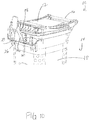
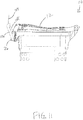
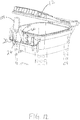
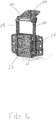
- FIGS. 9-15 illustrate another exemplary embodiment of a locking device 20.
- Locking device 20 includes many of the same elements described above including the rotatable shaft 28, the cam 30, the first paddle 32, the second paddle 34, the paddle actuation device 36, the locking block 38, the magnetic device 40, and the blocking device 96.
- locking arm 102 as illustrated in FIGS. 9-15 , differs from locking arm 22 described above.
- locking arm 102 is an articulated body that includes a locking plate 104, a first locking shaft 106, and a second locking shaft 108.
- the locking plate 104 includes a mounting plate 110, where one end of the first locking shaft 106 and one end of the second locking shaft 108 are piviotably coupled to the mounting plate 110.
- the first locking shaft 106 is pivotably coupled to an outer surface 112 of the mounting plate 110 and the second locking shaft 108 is pivotably coupled to an inner surface 114 of the mounting plate, as shown in FIG. 15 .
- the first locking shaft 106 and the second locking shaft 108 can be pivotably coupled to the same surface (e.g., either the inner surface 114 or the outer surface 112).
- the locking plate 104 may further include an opening 116 formed at an edge of the locking plate 104.
- the other end of the first locking shaft 106 is connected to the rotatable shaft 28 in a similar manner as the locking arm 22.
- the other end of the second locking shaft 106 is mounted to the shaft 64.
- the locking plate 104 In operation, when the container 10 is in an upright position and the locking device 20 is in the locked position, the locking plate 104 is located over the top surface of the lid 12 of the container 10, as illustrated in FIG. 9 , and prevents the lid 12 from opening.
- a force is applied to the paddle actuation device lever 60 causing the planar member 62 to interact with the first paddle 32 and disengage the first paddle 32 from the first sloping surface 70, as previously described above.
- the locking plate 104 can translate from a horizontal position to a vertical position, as illustrated in FIGS. 10 and 11 .
- the second locking shaft 108 is free to extend away from the containment body 14 and the first locking shaft 106 causes the rotatable shaft 28 and cam 30 to rotate within the locking device housing 26, as previously described above.
- the locking device 20, specifically, the locking plate 104 is positioned such that no contamination of the locking device occurs when the contents of the container 10 are removed.
- the moment of inertia of the locking plate 104 is different from the rest of the locking arm 102 due to the first locking shaft 106 and the second locking shaft 108 being pivotably mounted to the locking plate 104.
- the locking device 20 can further include spacing members 118, which may act as bumpers to protect the locking device 20 from impact.
- the spacing members 118 extend from either side of the locking device housing 26. While spacing members 118 are illustrated as having a curved shape, one of ordinary skill in the art would recognize that the spacing members 118 can have any shape.
- the spacing members 118 can be made of the same material as the locking device housing 26 or a different material from the locking device housing 26.
- the spacing members 118 can be configured to provide a predetermined space between the locking device 20 and a content removal device such as an automatic arm on a refuse truck.
Claims (13)
- Dispositif de verrouillage (20) pour un conteneur (10), où le dispositif de verrouillage (20) comprend :a. un bloc de verrouillage (38) déplaçable entre une position verrouillée et une position non verrouillée, la position non verrouillée permet au dispositif de verrouillage (20) d'être déverrouillé et la position verrouillée permet de garder le dispositif de verrouillage (20) verrouillé ;b. une seconde plaque (34) présentant des première et seconde extrémités opposées, la première extrémité est montée sur une première articulation et la seconde extrémité est montée de manière amovible au moyen d'une attraction magnétique sur une surface d'attache, de sorte que lorsque la deuxième extrémité est détachée de la surface, elle peut être positionnée pour empêcher le bloc de verrouillage (38) d'être déplacé à la position non verrouillée ;c. un bras de verrouillage (22) présentant une extrémité couplée à un arbre rotatif (28) et étant déplaçable entre une position ouverte et une position fermée ; etd. une came (30) couplée à l'arbre rotatif (28), où la came (30) est configurée pour tourner avec l'arbre (28), et où lorsque le bras de verrouillage (22) se trouve à la position ouverte, la came pousse le bloc de verrouillage (38) vers la position non verrouillée.
- Dispositif de verrouillage selon la revendication 1, dans lequel a) le bloc de verrouillage (38) présente un canal (66), la surface d'attache, et une première surface inclinée (70) opposée à la surface d'attache, et une seconde surface inclinée (72) espacée de la première surface inclinée (70), lorsque la seconde plaque (34) est attachée sur la surface d'attache, la seconde plaque (34) est alignée avec le canal (66), et lorsque la seconde plaque (34) est détachée de la surface d'attache, la seconde plaque (34) peut être positionnée de sorte à être en contact avec la première surface inclinée (70) pour empêcher le bloc de verrouillage d'être déplacé à la position non verrouillée.
- Dispositif de verrouillage selon la revendication 2, comprenant en outre une première plaque (32) présentant des première et seconde extrémités opposées, la première extrémité est montée sur une seconde articulation et la seconde extrémité peut être positionnée de sorte à être alignée avec le canal (66) ou à être en contact avec la seconde surface inclinée (72), de préférence la seconde extrémité de la première plaque (32) est en contact avec la seconde surface inclinée (72) lorsque le dispositif de verrouillage (20) se trouve dans une position à la verticale et que le bras de verrouillage (22) se trouve à la position fermée.
- Dispositif de verrouillage selon la revendication 3, comprenant en outre un dispositif d'actionnement de plaque (36) présentant un levier (60) couplé à un élément plan (62), où l'élément plan (62) du dispositif d'actionnement de plaque (36) est configuré pour placer la première plaque (32) en alignement avec le canal (66) du bloc de verrouillage (38) lorsqu'une force est appliquée sur le levier (60) du dispositif d'actionnement de plaque (36).
- Dispositif de verrouillage selon la revendication 4, comprenant en outre un dispositif de blocage (96) présentant une cavité (94) ménagée dans une surface inférieure du dispositif de blocage, où la cavité (94) est configurée pour recevoir un dispositif d'arrêt (86) ; et
où le bloc de verrouillage (38) comprend en outre un compartiment pour dispositif de blocage (76) coopérant avec la cavité (94) du dispositif de blocage (96) pour contenir le dispositif d'arrêt (86). - Dispositif de verrouillage selon la revendication 5, dans lequel a) le dispositif d'arrêt (86) est une bille ; ou b) le dispositif d'arrêt (86) peut être positionné à une première position lorsque le dispositif de verrouillage (20) est à la verticale et que le bloc de verrouillage (38) se trouve à la position verrouillée, à une deuxième position et à une troisième position lorsque le dispositif de verrouillage (20) se trouve sur son côté, dans les deuxième et troisième positions, le dispositif d'arrêt (86) empêche le bloc de verrouillage (38) d'être déplacé à la position non verrouillée.
- Conteneur à déchets (10) comprenant un corps de contenance (14), et un couvercle (12) monté de manière pivotante sur le corps de contenance (14), et le dispositif de verrouillage selon la revendication 1 monté sur une paroi (18) du corps de contenance (14).
- Conteneur à déchets selon la revendication 7, dans lequel a) le bloc de verrouillage (38) présente un canal (66), la surface d'attache, et une première surface inclinée (70) opposée à la surface d'attache, et une seconde surface inclinée (72) espacée de la première surface inclinée (70), lorsque la seconde plaque (34) est attachée sur la surface d'attache, la seconde plaque (34) est alignée avec le canal (66), et lorsque la seconde plaque (34) est détachée de la surface d'attache, la seconde plaque (34) peut être positionnée de sorte à être en contact avec la première surface inclinée (70) pour empêcher le bloc de verrouillage d'être déplacé à la position non verrouillée.
- Conteneur à déchets selon la revendication 8, comprenant en outre une première plaque (32) présentant des première et seconde extrémités opposées, la première extrémité est montée sur une seconde articulation et la seconde extrémité peut être positionnée de sorte à être alignée avec le canal (66) ou à être en contact avec la seconde surface inclinée (72), de préférence la seconde extrémité de la première plaque (32) est en contact avec la seconde surface inclinée (72) lorsque le dispositif de verrouillage (20) se trouve dans une position à la verticale et que le bras de verrouillage (22) se trouve à la position fermée.
- Conteneur à déchets selon la revendication 9, comprenant en outre un dispositif d'actionnement de plaque (36) présentant un levier (60) couplé à un élément plan (62), où l'élément plan (62) du dispositif d'actionnement de plaque (36) est configuré pour placer la première plaque (32) en alignement avec le canal (66) du bloc de verrouillage (38) lorsqu'une force est appliquée sur le levier (60) du dispositif d'actionnement de plaque (36).
- Conteneur à déchets selon la revendication 10, comprenant en outre un dispositif de blocage (96) présentant une cavité (94) ménagée dans une surface inférieure du dispositif de blocage, où la cavité (94) est configurée pour recevoir un dispositif d'arrêt (86) ; et
où le bloc de verrouillage (38) comprend en outre un compartiment pour dispositif de blocage (76) coopérant avec la cavité (94) du dispositif de blocage (96) pour contenir le dispositif d'arrêt (86). - Conteneur à déchets selon la revendication 11, dans lequel a) le dispositif d'arrêt (86) est une bille ; ou b) le dispositif d'arrêt (86) peut être positionné à une première position lorsque le dispositif de verrouillage (20) est à la verticale et que le bloc de verrouillage (38) se trouve à la position verrouillée, à une deuxième position et à une troisième position lorsque le dispositif de verrouillage (20) se trouve sur son côté, dans les deuxième et troisième positions, le dispositif d'arrêt (86) empêche le bloc de verrouillage (38) d'être déplacé à la position non verrouillée.
- Procédé de fabrication d'un conteneur à déchets comprenant les étapes consistant à :a. fournir un conteneur à déchets (10) contenant un corps de contenance (14) et un couvercle (12) monté de manière pivotante sur le corps de contenance (14) ; etb. monter le dispositif de verrouillage selon la revendication 1 sur une paroi (18) du corps de contenance (14).
Applications Claiming Priority (3)
| Application Number | Priority Date | Filing Date | Title |
|---|---|---|---|
| US201462089599P | 2014-12-09 | 2014-12-09 | |
| US201562104303P | 2015-01-16 | 2015-01-16 | |
| PCT/US2015/064639 WO2016094487A1 (fr) | 2014-12-09 | 2015-12-09 | Dispositif de verrouillage pour un conteneur |
Publications (2)
| Publication Number | Publication Date |
|---|---|
| EP3230176A1 EP3230176A1 (fr) | 2017-10-18 |
| EP3230176B1 true EP3230176B1 (fr) | 2020-04-29 |
Family
ID=55069109
Family Applications (1)
| Application Number | Title | Priority Date | Filing Date |
|---|---|---|---|
| EP15819953.9A Active EP3230176B1 (fr) | 2014-12-09 | 2015-12-09 | Dispositif de verrouillage pour un conteneur et procédé de fabrication d'un conteneur à déchets |
Country Status (5)
| Country | Link |
|---|---|
| US (2) | US9580244B2 (fr) |
| EP (1) | EP3230176B1 (fr) |
| AU (1) | AU2015360673A1 (fr) |
| CA (1) | CA2973338C (fr) |
| WO (1) | WO2016094487A1 (fr) |
Families Citing this family (19)
| Publication number | Priority date | Publication date | Assignee | Title |
|---|---|---|---|---|
| DE102012211098A1 (de) * | 2012-06-28 | 2014-01-23 | Robert Bosch Gmbh | Verschlussvorrichtung |
| US9963276B1 (en) * | 2014-04-25 | 2018-05-08 | The Eastern Company | Latch and release mechanisms for waste containers |
| US10100554B2 (en) * | 2014-08-26 | 2018-10-16 | Northland Products, Inc. | Gravity-actuated latch mechanism |
| US10279998B2 (en) * | 2015-01-14 | 2019-05-07 | Kann Manufacturing Corporation | Manual cart latch |
| WO2017027616A1 (fr) * | 2015-08-10 | 2017-02-16 | Serio-Us Industries, Inc. | Dispositif de verrouillage pour récipient pour ordures |
| US9821957B1 (en) * | 2015-08-18 | 2017-11-21 | David Robert Hurst | Locking apparatus for a refuse container lid |
| CN105737223B (zh) * | 2016-02-01 | 2017-12-19 | 广东美的厨房电器制造有限公司 | 带抽屉的厨房电器 |
| US10781041B2 (en) * | 2016-05-06 | 2020-09-22 | Serio-Us Industries, Inc. | Locking device |
| US10221010B2 (en) * | 2016-05-06 | 2019-03-05 | Serio-Us Industries, Inc. | Locking device for container |
| USD789770S1 (en) | 2016-06-02 | 2017-06-20 | Serio-Us Industries, Inc. | Container lock |
| US10633179B2 (en) * | 2017-01-24 | 2020-04-28 | Michael C Schoonmaker | Garbage can lid locking device for use with truck having a mechanical arm |
| CN107150871B (zh) * | 2017-06-05 | 2022-11-11 | 广东亿科智能家居科技有限公司 | 一种按压式垃圾桶盖及垃圾桶 |
| CA3023327C (fr) * | 2018-11-07 | 2022-05-10 | Matthew Moffatt | Systeme de poubelle a verrouillage automatique et methode |
| US11235925B1 (en) | 2019-04-03 | 2022-02-01 | Piyush Sheth | Collection bin locking assembly with gravity operated release mechanism |
| US11345540B1 (en) * | 2019-10-23 | 2022-05-31 | Nicholas DiBartolo | Locking container lid with actuating handle |
| US11745942B2 (en) * | 2020-03-02 | 2023-09-05 | Serio-Us Industries, Inc. | Locking device for waste container and methods |
| US11932485B2 (en) * | 2021-02-25 | 2024-03-19 | Krishiv PATEL | Locking mechanism for container |
| US20220281681A1 (en) * | 2021-03-04 | 2022-09-08 | Serio-Us Industries, Inc. | Locking device and methods |
| US20230032263A1 (en) * | 2021-07-28 | 2023-02-02 | Christopher R H Ganz | Trash Can Automatic Lid Stabilizer |
Family Cites Families (21)
| Publication number | Priority date | Publication date | Assignee | Title |
|---|---|---|---|---|
| US3674298A (en) | 1970-10-30 | 1972-07-04 | Balazs Vekony | Garbage can lid lock |
| FR2675478A1 (fr) | 1991-04-17 | 1992-10-23 | Plastic Omnium Cie | Dispositif de verrouillage d'un couvercle sur une cuve de conteneur et conteneur comprenant un tel dispositif. |
| US5415314A (en) | 1993-06-21 | 1995-05-16 | Mccollum; Chris A. | Gravity locking mechanism employing first and second pendulums for securing the lid of a refuse container |
| US5419598A (en) * | 1994-04-28 | 1995-05-30 | Kreitzer; Joseph D. | Lock for trash bin |
| US5772061A (en) | 1994-12-15 | 1998-06-30 | Egbert H. Taylor & Company Limited | Refuse containers |
| US5599050A (en) | 1995-09-27 | 1997-02-04 | Tinsley; Harry | Lid-locking device for trash containers |
| US5772264A (en) | 1996-03-25 | 1998-06-30 | Bettenhausen; Shane | Gravity operated latch for a refuse container lid |
| FR2798120B1 (fr) | 1999-09-03 | 2001-11-16 | Citec Environnement | Dispositif automatique par gravite de verrouillage/ deverrouillage du couvercle d'un bac et bac equipe d'un tel dispositif |
| US6808080B2 (en) | 2002-03-08 | 2004-10-26 | Delaware Capital Formation, Inc. | Container latching method and apparatus |
| CA2406301A1 (fr) | 2002-10-02 | 2004-04-02 | Warren Thomas Walker | Systeme de fixation de couvercle de poubelle |
| US7004514B2 (en) | 2003-07-29 | 2006-02-28 | Ap Technoglass | Safety locking device |
| US7086557B2 (en) | 2003-09-22 | 2006-08-08 | Gill Industries, Inc. | Animal resistant trash container lid and trash container system |
| US20080169288A1 (en) | 2007-01-12 | 2008-07-17 | Michael Dawn | Receptacle having a securable lid |
| DE102007039351A1 (de) * | 2007-05-03 | 2008-11-06 | S. Franzen Söhne GmbH & Co. KG | Mülltonnenverschluss |
| US8485382B2 (en) | 2008-03-07 | 2013-07-16 | Orbis Canada Limited | Refuse container |
| US8313126B2 (en) | 2008-10-23 | 2012-11-20 | Hodge Products, Inc. | Gravity release locking apparatus for trash container |
| US20120273495A1 (en) | 2011-04-27 | 2012-11-01 | D Alessandro Lorraine | Animal Deterrent Trash System |
| US8810361B2 (en) | 2011-08-09 | 2014-08-19 | Shervin Moloudi | Electronically augmented smart lock for trash containers |
| US20140069926A1 (en) | 2012-09-13 | 2014-03-13 | Northland Products, Inc. | Latch system with inertial lock mechanism |
| EP2948393A1 (fr) * | 2013-01-25 | 2015-12-02 | Serio-US Industries Inc. | Contenant ayant un ensemble de loquet automatique |
| US9376255B2 (en) | 2013-02-22 | 2016-06-28 | Orbis Corporation | Waste container with gravity latch |
-
2015
- 2015-12-09 US US14/963,499 patent/US9580244B2/en active Active
- 2015-12-09 CA CA2973338A patent/CA2973338C/fr active Active
- 2015-12-09 WO PCT/US2015/064639 patent/WO2016094487A1/fr active Application Filing
- 2015-12-09 AU AU2015360673A patent/AU2015360673A1/en not_active Abandoned
- 2015-12-09 EP EP15819953.9A patent/EP3230176B1/fr active Active
-
2017
- 2017-02-28 US US15/445,368 patent/US10046911B2/en active Active
Non-Patent Citations (1)
| Title |
|---|
| None * |
Also Published As
| Publication number | Publication date |
|---|---|
| US20160159570A1 (en) | 2016-06-09 |
| CA2973338C (fr) | 2023-07-11 |
| US9580244B2 (en) | 2017-02-28 |
| US10046911B2 (en) | 2018-08-14 |
| US20170166397A1 (en) | 2017-06-15 |
| AU2015360673A1 (en) | 2017-07-27 |
| WO2016094487A1 (fr) | 2016-06-16 |
| EP3230176A1 (fr) | 2017-10-18 |
| CA2973338A1 (fr) | 2016-06-16 |
Similar Documents
| Publication | Publication Date | Title |
|---|---|---|
| EP3230176B1 (fr) | Dispositif de verrouillage pour un conteneur et procédé de fabrication d'un conteneur à déchets | |
| EP3230175B1 (fr) | Dispositif de verrouillage pour un récipient et procédé de fabrication d'un récipient à déchets | |
| US10279995B2 (en) | Locking device for waste container | |
| US9828177B2 (en) | Waste container with gravity latch and latch deactivation system | |
| CA2843339C (fr) | Contenant a dechets dote d'un dispositif de blocage par gravite | |
| CA2535274C (fr) | Benne a dechets | |
| US20150151910A1 (en) | Refuse Container | |
| CA2521412A1 (fr) | Conteneur a dechets | |
| US10221010B2 (en) | Locking device for container | |
| US8931655B2 (en) | Bin lid and bin incorporating same | |
| US11345540B1 (en) | Locking container lid with actuating handle | |
| CA2931716C (fr) | Mecanisme de verrou de ramasse-poussiere | |
| CA2819806C (fr) | Conteneur a deverrouillage automatique |
Legal Events
| Date | Code | Title | Description |
|---|---|---|---|
| STAA | Information on the status of an ep patent application or granted ep patent |
Free format text: STATUS: THE INTERNATIONAL PUBLICATION HAS BEEN MADE |
|
| PUAI | Public reference made under article 153(3) epc to a published international application that has entered the european phase |
Free format text: ORIGINAL CODE: 0009012 |
|
| STAA | Information on the status of an ep patent application or granted ep patent |
Free format text: STATUS: REQUEST FOR EXAMINATION WAS MADE |
|
| 17P | Request for examination filed |
Effective date: 20170710 |
|
| AK | Designated contracting states |
Kind code of ref document: A1 Designated state(s): AL AT BE BG CH CY CZ DE DK EE ES FI FR GB GR HR HU IE IS IT LI LT LU LV MC MK MT NL NO PL PT RO RS SE SI SK SM TR |
|
| AX | Request for extension of the european patent |
Extension state: BA ME |
|
| REG | Reference to a national code |
Ref country code: DE Ref legal event code: R079 Ref document number: 602015051799 Country of ref document: DE Free format text: PREVIOUS MAIN CLASS: B65F0001140000 Ipc: B65F0001160000 |
|
| RIC1 | Information provided on ipc code assigned before grant |
Ipc: E05B 65/52 20060101ALI20190516BHEP Ipc: E05B 47/00 20060101ALI20190516BHEP Ipc: B65F 1/16 20060101AFI20190516BHEP Ipc: E05B 15/00 20060101ALI20190516BHEP Ipc: E05B 17/20 20060101ALI20190516BHEP |
|
| GRAP | Despatch of communication of intention to grant a patent |
Free format text: ORIGINAL CODE: EPIDOSNIGR1 |
|
| STAA | Information on the status of an ep patent application or granted ep patent |
Free format text: STATUS: GRANT OF PATENT IS INTENDED |
|
| INTG | Intention to grant announced |
Effective date: 20190704 |
|
| GRAS | Grant fee paid |
Free format text: ORIGINAL CODE: EPIDOSNIGR3 |
|
| GRAJ | Information related to disapproval of communication of intention to grant by the applicant or resumption of examination proceedings by the epo deleted |
Free format text: ORIGINAL CODE: EPIDOSDIGR1 |
|
| GRAL | Information related to payment of fee for publishing/printing deleted |
Free format text: ORIGINAL CODE: EPIDOSDIGR3 |
|
| STAA | Information on the status of an ep patent application or granted ep patent |
Free format text: STATUS: REQUEST FOR EXAMINATION WAS MADE |
|
| GRAP | Despatch of communication of intention to grant a patent |
Free format text: ORIGINAL CODE: EPIDOSNIGR1 |
|
| STAA | Information on the status of an ep patent application or granted ep patent |
Free format text: STATUS: GRANT OF PATENT IS INTENDED |
|
| INTG | Intention to grant announced |
Effective date: 20191213 |
|
| GRAA | (expected) grant |
Free format text: ORIGINAL CODE: 0009210 |
|
| STAA | Information on the status of an ep patent application or granted ep patent |
Free format text: STATUS: THE PATENT HAS BEEN GRANTED |
|
| AK | Designated contracting states |
Kind code of ref document: B1 Designated state(s): AL AT BE BG CH CY CZ DE DK EE ES FI FR GB GR HR HU IE IS IT LI LT LU LV MC MK MT NL NO PL PT RO RS SE SI SK SM TR |
|
| AX | Request for extension of the european patent |
Extension state: BA ME |
|
| REG | Reference to a national code |
Ref country code: GB Ref legal event code: FG4D |
|
| REG | Reference to a national code |
Ref country code: CH Ref legal event code: EP |
|
| REG | Reference to a national code |
Ref country code: AT Ref legal event code: REF Ref document number: 1262993 Country of ref document: AT Kind code of ref document: T Effective date: 20200515 |
|
| REG | Reference to a national code |
Ref country code: DE Ref legal event code: R096 Ref document number: 602015051799 Country of ref document: DE |
|
| REG | Reference to a national code |
Ref country code: IE Ref legal event code: FG4D |
|
| REG | Reference to a national code |
Ref country code: NL Ref legal event code: MP Effective date: 20200429 |
|
| REG | Reference to a national code |
Ref country code: LT Ref legal event code: MG4D |
|
| PG25 | Lapsed in a contracting state [announced via postgrant information from national office to epo] |
Ref country code: IS Free format text: LAPSE BECAUSE OF FAILURE TO SUBMIT A TRANSLATION OF THE DESCRIPTION OR TO PAY THE FEE WITHIN THE PRESCRIBED TIME-LIMIT Effective date: 20200829 Ref country code: PT Free format text: LAPSE BECAUSE OF FAILURE TO SUBMIT A TRANSLATION OF THE DESCRIPTION OR TO PAY THE FEE WITHIN THE PRESCRIBED TIME-LIMIT Effective date: 20200831 Ref country code: GR Free format text: LAPSE BECAUSE OF FAILURE TO SUBMIT A TRANSLATION OF THE DESCRIPTION OR TO PAY THE FEE WITHIN THE PRESCRIBED TIME-LIMIT Effective date: 20200730 Ref country code: FI Free format text: LAPSE BECAUSE OF FAILURE TO SUBMIT A TRANSLATION OF THE DESCRIPTION OR TO PAY THE FEE WITHIN THE PRESCRIBED TIME-LIMIT Effective date: 20200429 Ref country code: NO Free format text: LAPSE BECAUSE OF FAILURE TO SUBMIT A TRANSLATION OF THE DESCRIPTION OR TO PAY THE FEE WITHIN THE PRESCRIBED TIME-LIMIT Effective date: 20200729 Ref country code: SE Free format text: LAPSE BECAUSE OF FAILURE TO SUBMIT A TRANSLATION OF THE DESCRIPTION OR TO PAY THE FEE WITHIN THE PRESCRIBED TIME-LIMIT Effective date: 20200429 Ref country code: LT Free format text: LAPSE BECAUSE OF FAILURE TO SUBMIT A TRANSLATION OF THE DESCRIPTION OR TO PAY THE FEE WITHIN THE PRESCRIBED TIME-LIMIT Effective date: 20200429 |
|
| REG | Reference to a national code |
Ref country code: AT Ref legal event code: MK05 Ref document number: 1262993 Country of ref document: AT Kind code of ref document: T Effective date: 20200429 |
|
| PG25 | Lapsed in a contracting state [announced via postgrant information from national office to epo] |
Ref country code: RS Free format text: LAPSE BECAUSE OF FAILURE TO SUBMIT A TRANSLATION OF THE DESCRIPTION OR TO PAY THE FEE WITHIN THE PRESCRIBED TIME-LIMIT Effective date: 20200429 Ref country code: BG Free format text: LAPSE BECAUSE OF FAILURE TO SUBMIT A TRANSLATION OF THE DESCRIPTION OR TO PAY THE FEE WITHIN THE PRESCRIBED TIME-LIMIT Effective date: 20200729 Ref country code: LV Free format text: LAPSE BECAUSE OF FAILURE TO SUBMIT A TRANSLATION OF THE DESCRIPTION OR TO PAY THE FEE WITHIN THE PRESCRIBED TIME-LIMIT Effective date: 20200429 Ref country code: HR Free format text: LAPSE BECAUSE OF FAILURE TO SUBMIT A TRANSLATION OF THE DESCRIPTION OR TO PAY THE FEE WITHIN THE PRESCRIBED TIME-LIMIT Effective date: 20200429 |
|
| PG25 | Lapsed in a contracting state [announced via postgrant information from national office to epo] |
Ref country code: AL Free format text: LAPSE BECAUSE OF FAILURE TO SUBMIT A TRANSLATION OF THE DESCRIPTION OR TO PAY THE FEE WITHIN THE PRESCRIBED TIME-LIMIT Effective date: 20200429 Ref country code: NL Free format text: LAPSE BECAUSE OF FAILURE TO SUBMIT A TRANSLATION OF THE DESCRIPTION OR TO PAY THE FEE WITHIN THE PRESCRIBED TIME-LIMIT Effective date: 20200429 |
|
| PG25 | Lapsed in a contracting state [announced via postgrant information from national office to epo] |
Ref country code: ES Free format text: LAPSE BECAUSE OF FAILURE TO SUBMIT A TRANSLATION OF THE DESCRIPTION OR TO PAY THE FEE WITHIN THE PRESCRIBED TIME-LIMIT Effective date: 20200429 Ref country code: DK Free format text: LAPSE BECAUSE OF FAILURE TO SUBMIT A TRANSLATION OF THE DESCRIPTION OR TO PAY THE FEE WITHIN THE PRESCRIBED TIME-LIMIT Effective date: 20200429 Ref country code: IT Free format text: LAPSE BECAUSE OF FAILURE TO SUBMIT A TRANSLATION OF THE DESCRIPTION OR TO PAY THE FEE WITHIN THE PRESCRIBED TIME-LIMIT Effective date: 20200429 Ref country code: SM Free format text: LAPSE BECAUSE OF FAILURE TO SUBMIT A TRANSLATION OF THE DESCRIPTION OR TO PAY THE FEE WITHIN THE PRESCRIBED TIME-LIMIT Effective date: 20200429 Ref country code: EE Free format text: LAPSE BECAUSE OF FAILURE TO SUBMIT A TRANSLATION OF THE DESCRIPTION OR TO PAY THE FEE WITHIN THE PRESCRIBED TIME-LIMIT Effective date: 20200429 Ref country code: AT Free format text: LAPSE BECAUSE OF FAILURE TO SUBMIT A TRANSLATION OF THE DESCRIPTION OR TO PAY THE FEE WITHIN THE PRESCRIBED TIME-LIMIT Effective date: 20200429 Ref country code: RO Free format text: LAPSE BECAUSE OF FAILURE TO SUBMIT A TRANSLATION OF THE DESCRIPTION OR TO PAY THE FEE WITHIN THE PRESCRIBED TIME-LIMIT Effective date: 20200429 Ref country code: CZ Free format text: LAPSE BECAUSE OF FAILURE TO SUBMIT A TRANSLATION OF THE DESCRIPTION OR TO PAY THE FEE WITHIN THE PRESCRIBED TIME-LIMIT Effective date: 20200429 |
|
| REG | Reference to a national code |
Ref country code: DE Ref legal event code: R097 Ref document number: 602015051799 Country of ref document: DE |
|
| PG25 | Lapsed in a contracting state [announced via postgrant information from national office to epo] |
Ref country code: PL Free format text: LAPSE BECAUSE OF FAILURE TO SUBMIT A TRANSLATION OF THE DESCRIPTION OR TO PAY THE FEE WITHIN THE PRESCRIBED TIME-LIMIT Effective date: 20200429 Ref country code: SK Free format text: LAPSE BECAUSE OF FAILURE TO SUBMIT A TRANSLATION OF THE DESCRIPTION OR TO PAY THE FEE WITHIN THE PRESCRIBED TIME-LIMIT Effective date: 20200429 |
|
| VS25 | Lapsed in a validation state [announced via postgrant information from nat. office to epo] |
Ref country code: MD Free format text: LAPSE BECAUSE OF FAILURE TO SUBMIT A TRANSLATION OF THE DESCRIPTION OR TO PAY THE FEE WITHIN THE PRESCRIBED TIME-LIMIT Effective date: 20200429 |
|
| PLBE | No opposition filed within time limit |
Free format text: ORIGINAL CODE: 0009261 |
|
| STAA | Information on the status of an ep patent application or granted ep patent |
Free format text: STATUS: NO OPPOSITION FILED WITHIN TIME LIMIT |
|
| 26N | No opposition filed |
Effective date: 20210201 |
|
| PG25 | Lapsed in a contracting state [announced via postgrant information from national office to epo] |
Ref country code: SI Free format text: LAPSE BECAUSE OF FAILURE TO SUBMIT A TRANSLATION OF THE DESCRIPTION OR TO PAY THE FEE WITHIN THE PRESCRIBED TIME-LIMIT Effective date: 20200429 |
|
| VS25 | Lapsed in a validation state [announced via postgrant information from nat. office to epo] |
Ref country code: MA Free format text: LAPSE BECAUSE OF FAILURE TO SUBMIT A TRANSLATION OF THE DESCRIPTION OR TO PAY THE FEE WITHIN THE PRESCRIBED TIME-LIMIT Effective date: 20200429 |
|
| REG | Reference to a national code |
Ref country code: CH Ref legal event code: PL |
|
| PG25 | Lapsed in a contracting state [announced via postgrant information from national office to epo] |
Ref country code: MC Free format text: LAPSE BECAUSE OF FAILURE TO SUBMIT A TRANSLATION OF THE DESCRIPTION OR TO PAY THE FEE WITHIN THE PRESCRIBED TIME-LIMIT Effective date: 20200429 |
|
| REG | Reference to a national code |
Ref country code: BE Ref legal event code: MM Effective date: 20201231 |
|
| PG25 | Lapsed in a contracting state [announced via postgrant information from national office to epo] |
Ref country code: LU Free format text: LAPSE BECAUSE OF NON-PAYMENT OF DUE FEES Effective date: 20201209 Ref country code: IE Free format text: LAPSE BECAUSE OF NON-PAYMENT OF DUE FEES Effective date: 20201209 |
|
| PG25 | Lapsed in a contracting state [announced via postgrant information from national office to epo] |
Ref country code: CH Free format text: LAPSE BECAUSE OF NON-PAYMENT OF DUE FEES Effective date: 20201231 Ref country code: LI Free format text: LAPSE BECAUSE OF NON-PAYMENT OF DUE FEES Effective date: 20201231 |
|
| PG25 | Lapsed in a contracting state [announced via postgrant information from national office to epo] |
Ref country code: TR Free format text: LAPSE BECAUSE OF FAILURE TO SUBMIT A TRANSLATION OF THE DESCRIPTION OR TO PAY THE FEE WITHIN THE PRESCRIBED TIME-LIMIT Effective date: 20200429 Ref country code: MT Free format text: LAPSE BECAUSE OF FAILURE TO SUBMIT A TRANSLATION OF THE DESCRIPTION OR TO PAY THE FEE WITHIN THE PRESCRIBED TIME-LIMIT Effective date: 20200429 Ref country code: CY Free format text: LAPSE BECAUSE OF FAILURE TO SUBMIT A TRANSLATION OF THE DESCRIPTION OR TO PAY THE FEE WITHIN THE PRESCRIBED TIME-LIMIT Effective date: 20200429 |
|
| PG25 | Lapsed in a contracting state [announced via postgrant information from national office to epo] |
Ref country code: MK Free format text: LAPSE BECAUSE OF FAILURE TO SUBMIT A TRANSLATION OF THE DESCRIPTION OR TO PAY THE FEE WITHIN THE PRESCRIBED TIME-LIMIT Effective date: 20200429 |
|
| PG25 | Lapsed in a contracting state [announced via postgrant information from national office to epo] |
Ref country code: BE Free format text: LAPSE BECAUSE OF NON-PAYMENT OF DUE FEES Effective date: 20201231 |
|
| PGFP | Annual fee paid to national office [announced via postgrant information from national office to epo] |
Ref country code: GB Payment date: 20221229 Year of fee payment: 8 Ref country code: FR Payment date: 20221229 Year of fee payment: 8 |
|
| PGFP | Annual fee paid to national office [announced via postgrant information from national office to epo] |
Ref country code: DE Payment date: 20221222 Year of fee payment: 8 |
|
| P01 | Opt-out of the competence of the unified patent court (upc) registered |
Effective date: 20230606 |
|
| REG | Reference to a national code |
Ref country code: DE Ref legal event code: R082 Ref document number: 602015051799 Country of ref document: DE |