EP3229574A2 - Circuit board assemblies - Google Patents
Circuit board assemblies Download PDFInfo
- Publication number
- EP3229574A2 EP3229574A2 EP17165363.7A EP17165363A EP3229574A2 EP 3229574 A2 EP3229574 A2 EP 3229574A2 EP 17165363 A EP17165363 A EP 17165363A EP 3229574 A2 EP3229574 A2 EP 3229574A2
- Authority
- EP
- European Patent Office
- Prior art keywords
- deflector
- arrangement
- circuit board
- air flow
- electronic component
- Prior art date
- Legal status (The legal status is an assumption and is not a legal conclusion. Google has not performed a legal analysis and makes no representation as to the accuracy of the status listed.)
- Granted
Links
Images


Classifications
-
- H—ELECTRICITY
- H05—ELECTRIC TECHNIQUES NOT OTHERWISE PROVIDED FOR
- H05K—PRINTED CIRCUITS; CASINGS OR CONSTRUCTIONAL DETAILS OF ELECTRIC APPARATUS; MANUFACTURE OF ASSEMBLAGES OF ELECTRICAL COMPONENTS
- H05K7/00—Constructional details common to different types of electric apparatus
- H05K7/20—Modifications to facilitate cooling, ventilating, or heating
- H05K7/20009—Modifications to facilitate cooling, ventilating, or heating using a gaseous coolant in electronic enclosures
- H05K7/20136—Forced ventilation, e.g. by fans
- H05K7/20145—Means for directing air flow, e.g. ducts, deflectors, plenum or guides
-
- H—ELECTRICITY
- H05—ELECTRIC TECHNIQUES NOT OTHERWISE PROVIDED FOR
- H05K—PRINTED CIRCUITS; CASINGS OR CONSTRUCTIONAL DETAILS OF ELECTRIC APPARATUS; MANUFACTURE OF ASSEMBLAGES OF ELECTRICAL COMPONENTS
- H05K7/00—Constructional details common to different types of electric apparatus
- H05K7/20—Modifications to facilitate cooling, ventilating, or heating
- H05K7/20009—Modifications to facilitate cooling, ventilating, or heating using a gaseous coolant in electronic enclosures
- H05K7/20209—Thermal management, e.g. fan control
Definitions
- the present disclosure relates to circuit board assemblies, more specifically to circuit board assemblies having flow channels for cooling.
- Electronic assemblies can develop hotspots that preclude air cooling despite the assembly as a whole being applicable for air cooling because these hotspots are too hot to be cooled by air cooling.
- Traditional systems focus on making airflow turbulent. This is not beneficial in flow stream that is already turbulent.
- a circuit thermal management arrangement can include a deflector configured to guide flow over an electronic component on a circuit board disposed in an air flow.
- the deflector can be configured to increase a speed of air flow over the electronic component or alter the airflow currents.
- the deflector can include an airfoil shape.
- the deflector can be positioned over a downstream end of the electronic component.
- the deflector can include a positive angle of incidence relative to the air flow.
- the deflector can be positioned over an upstream end of the electronic component.
- the deflector can include a negative angle of incidence relative to the air flow.
- the arrangement can further include a second deflector positioned over a downstream end of the electronic component.
- the second deflector can include a positive angle of incidence relative to the air flow.
- the first deflector and the second deflector can be connected via a connector member such that the first deflector, the second deflector, and the connector member overlay the electronic component.
- the connector member can be parallel relative to a direction of the flow in the air flow.
- a method for thermal management of a circuit board includes modifying an air flow over the circuit board to increase speed or direction the air flow over a component of the circuit board using a deflector.
- FIG. 1 an illustrative view of an embodiment of an arrangement in accordance with the disclosure is shown in Fig. 1 and is designated generally by reference character 100.
- FIGs. 2-7 Other embodiments and/or aspects of this disclosure are shown in Figs. 2-7 .
- the systems and methods described herein can be used to enhance thermal transfer in electronic circuits.
- a circuit board arrangement 100 can include one or more electronic components 107 (e.g., that can become hot) on a circuit board 109.
- a deflector 105 can be disposed over the electronic components 107.
- the deflector 105 can be configured to guide flow over electronic components 107 on a circuit board 109.
- the deflector 105 can be configured to increase a speed of air flow over the electronic component (e.g., by directing flow down over the electronic component 107 as shown in Fig. 2 ).
- Any other suitable function of the deflector 105 for flow modification e.g., turbulence creation
- is contemplated herein e.g., for cooling or heating).
- the deflector 105 can be held over the electronic components 107 via one or more structures (e.g., walls 101).
- the walls 101 can form at least a portion of a flow channel 103 where the air flow is guided through.
- the deflector 105 can include an airfoil shape (e.g., as shown in Fig. 3 ). Any other shape (e.g., a linear cross-sectional shape such as a plate as shown in Fig. 2 ) is contemplated herein.
- the deflector 105 can be positioned over a downstream end of the electronic component 107. As shown, the deflector 105 can include a positive angle of incidence relative to a flow in the flow channel 103.
- the deflector 105 can be positioned over an upstream end of the electronic component 107. As shown, the deflector 105 can include a negative angle of incidence relative to a flow in the flow channel 103.
- a first deflector 105a can be positioned over an upstream end of the electronic component 107 and a second deflector 105b can be positioned over a downstream end of the electronic component 107.
- the first deflector 105a can include a negative angle of incidence relative to a flow in the flow channel 103 and the second deflector 105b can include a positive angle of incidence relative to a flow in the flow channel.
- the first deflector 105a and the second deflector 105b can be connected via a connector member 105c (e.g., and form a single piece as shown) such that the first deflector 105a, the second deflector 105b, and the connector member 105c overlay the electronic component 107.
- the connector member 105c can be parallel relative to a direction of the flow in the flow channel 103. While the first deflector 105a, the second deflector 105b, and the connector member 105c are shown as a single piece, it is contemplated that these components can be formed of any suitable number of pieces.
- Deflectors as described above were analyzed and tested via both computational fluid dynamics and experimental testing to determine the effect of various deflector positions and characteristics.
- the deflector 105 was placed at middle and downstream of an electronic component 107 (e.g., a third row of electronic components 107 in the direction of flow).
- the test results showed about 9% to about 22% loss in heat transfer coefficient (HTC) at about 0.35 cubic feet per minute (CFM) or a flow speed of about 0.12 m/s of airflow and about 4% to about 11% improvement of HTC at about 1.63 CFM or a flow speed of about 0.56 m/s.
- HTC heat transfer coefficient
- CFM cubic feet per minute
- the deflector 105 was repositioned to an upstream edge of the electronic component 107, which was shown to increase the velocity of air closer to the electronic component.
- This configuration provided about 0% to about 7% loss of HTC at 0.35 CFM and about 2% to about 12% improvement of HTC at about 1.63 CFM.
- a double deflector configuration was tested (having first deflector 105a and second deflector 105b).
- the electronic components 107 closest to the deflector e.g., the third row as shown
- the first and second deflectors 105a, 105b were plate shaped and were positioned about 2 mm upstream and about 2 mm downstream of the electronic component 107 (in a third row as shown).
- a second row of electronic components also saw improvement, while a first row of chips were seemingly unaffected.
- one or more deflectors can be added to a printed circuit assembly, for example, to direct the air flow and/or to increase the air velocity near a target component to improve the convective air cooling of the target component and/or adjacent components.
- Embodiments as described above can have positive cooling effect on the hot spots, for example.
- Embodiments as disclosed can improve convective cooling on a circuit board. It is contemplated that one having ordinary skill in the art, in view of this disclosure, can modify the deflector shape and/or placement in the flow channel for maximum cooling effectiveness.
- a method for thermal management of a circuit board includes modifying an air flow over the circuit board to increase speed or direction the air flow over a component of the circuit board using a deflector.
Landscapes
- Engineering & Computer Science (AREA)
- Microelectronics & Electronic Packaging (AREA)
- Physics & Mathematics (AREA)
- Thermal Sciences (AREA)
- Cooling Or The Like Of Electrical Apparatus (AREA)
- Cooling Or The Like Of Semiconductors Or Solid State Devices (AREA)
Abstract
Description
- The present disclosure relates to circuit board assemblies, more specifically to circuit board assemblies having flow channels for cooling.
- Electronic assemblies can develop hotspots that preclude air cooling despite the assembly as a whole being applicable for air cooling because these hotspots are too hot to be cooled by air cooling. Traditional systems focus on making airflow turbulent. This is not beneficial in flow stream that is already turbulent.
- Such conventional methods and systems have generally been considered satisfactory for their intended purpose. However, there is still a need in the art for improved cooling of circuit board assemblies. The present disclosure provides a solution for this need.
- A circuit thermal management arrangement can include a deflector configured to guide flow over an electronic component on a circuit board disposed in an air flow.
- The deflector can be configured to increase a speed of air flow over the electronic component or alter the airflow currents.
- In certain embodiments, the deflector can include an airfoil shape.
- In certain embodiments, the deflector can be positioned over a downstream end of the electronic component.
- The deflector can include a positive angle of incidence relative to the air flow.
- In certain embodiments, the deflector can be positioned over an upstream end of the electronic component.
- The deflector can include a negative angle of incidence relative to the air flow.
- The arrangement can further include a second deflector positioned over a downstream end of the electronic component.
- The second deflector can include a positive angle of incidence relative to the air flow.
- The first deflector and the second deflector can be connected via a connector member such that the first deflector, the second deflector, and the connector member overlay the electronic component.
- In certain embodiments, the connector member can be parallel relative to a direction of the flow in the air flow.
- A method for thermal management of a circuit board includes modifying an air flow over the circuit board to increase speed or direction the air flow over a component of the circuit board using a deflector.
- These and other features of the systems and methods of the subject disclosure will become more readily apparent to those skilled in the art from the following detailed description taken in conjunction with the drawings.
- So that those skilled in the art to which the subject disclosure appertains will readily understand how to make and use the devices and methods of the subject disclosure without undue experimentation, embodiments thereof will be described in detail herein below with reference to certain figures, wherein:
-
Fig. 1 is a perspective view of an embodiment of an arrangement in accordance with this disclosure, shown having an embodiment of a deflector extending across a flow channel; -
Fig. 2 is a cross-sectional schematic view of an embodiment of an arrangement in accordance with this disclosure, showing air flowing through the flow channel and having a plate deflector; -
Fig. 3 is a cross-sectional schematic view of an embodiment of an arrangement in accordance with this disclosure, showing air flowing through the flow channel and having an airfoil shaped deflector; -
Fig. 4 is a cross-sectional flow diagram of an embodiment of an arrangement in accordance with this disclosure; -
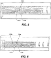
Fig. 5 is a cross-sectional flow diagram of an embodiment of an arrangement in accordance with this disclosure; -
Fig. 6 is a cross-sectional flow diagram of an embodiment of an arrangement in accordance with this disclosure; and -
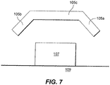
Fig. 7 is a partial cross-sectional view of an embodiment of an arrangement in accordance with this disclosure. - Reference will now be made to the drawings wherein like reference numerals identify similar structural features or aspects of the subject disclosure. For purposes of explanation and illustration, and not limitation, an illustrative view of an embodiment of an arrangement in accordance with the disclosure is shown in
Fig. 1 and is designated generally byreference character 100. Other embodiments and/or aspects of this disclosure are shown inFigs. 2-7 . The systems and methods described herein can be used to enhance thermal transfer in electronic circuits. - Referring to
Figs. 1 , acircuit board arrangement 100 can include one or more electronic components 107 (e.g., that can become hot) on acircuit board 109. Adeflector 105 can be disposed over theelectronic components 107. Thedeflector 105 can be configured to guide flow overelectronic components 107 on acircuit board 109. In certain embodiments, thedeflector 105 can be configured to increase a speed of air flow over the electronic component (e.g., by directing flow down over theelectronic component 107 as shown inFig. 2 ). Any other suitable function of thedeflector 105 for flow modification (e.g., turbulence creation) is contemplated herein (e.g., for cooling or heating). - In certain embodiments, as shown, the
deflector 105 can be held over theelectronic components 107 via one or more structures (e.g., walls 101). In the embodiment shown, thewalls 101 can form at least a portion of aflow channel 103 where the air flow is guided through. - In certain embodiments, the
deflector 105 can include an airfoil shape (e.g., as shown inFig. 3 ). Any other shape (e.g., a linear cross-sectional shape such as a plate as shown inFig. 2 ) is contemplated herein. - Referring to
Fig. 4 , in certain embodiments, thedeflector 105 can be positioned over a downstream end of theelectronic component 107. As shown, thedeflector 105 can include a positive angle of incidence relative to a flow in theflow channel 103. - Referring to
Fig. 5 , in certain embodiments, thedeflector 105 can be positioned over an upstream end of theelectronic component 107. As shown, thedeflector 105 can include a negative angle of incidence relative to a flow in theflow channel 103. - Referring to
Fig. 6 , in certain embodiments, afirst deflector 105a can be positioned over an upstream end of theelectronic component 107 and asecond deflector 105b can be positioned over a downstream end of theelectronic component 107. As shown, thefirst deflector 105a can include a negative angle of incidence relative to a flow in theflow channel 103 and thesecond deflector 105b can include a positive angle of incidence relative to a flow in the flow channel. - Referring to
Fig. 7 , in certain embodiments, thefirst deflector 105a and thesecond deflector 105b can be connected via aconnector member 105c (e.g., and form a single piece as shown) such that thefirst deflector 105a, thesecond deflector 105b, and theconnector member 105c overlay theelectronic component 107. As shown, in certain embodiments, theconnector member 105c can be parallel relative to a direction of the flow in theflow channel 103. While thefirst deflector 105a, thesecond deflector 105b, and theconnector member 105c are shown as a single piece, it is contemplated that these components can be formed of any suitable number of pieces. - Deflectors as described above were analyzed and tested via both computational fluid dynamics and experimental testing to determine the effect of various deflector positions and characteristics. Referring again to
Fig. 4 , thedeflector 105 was placed at middle and downstream of an electronic component 107 (e.g., a third row ofelectronic components 107 in the direction of flow). The test results showed about 9% to about 22% loss in heat transfer coefficient (HTC) at about 0.35 cubic feet per minute (CFM) or a flow speed of about 0.12 m/s of airflow and about 4% to about 11% improvement of HTC at about 1.63 CFM or a flow speed of about 0.56 m/s. - Referring again to
Fig. 5 , thedeflector 105 was repositioned to an upstream edge of theelectronic component 107, which was shown to increase the velocity of air closer to the electronic component. This configuration provided about 0% to about 7% loss of HTC at 0.35 CFM and about 2% to about 12% improvement of HTC at about 1.63 CFM. - Referring to
Fig. 6 , a double deflector configuration was tested (havingfirst deflector 105a andsecond deflector 105b). Theelectronic components 107 closest to the deflector (e.g., the third row as shown) were shown to have an HTC that was increased by about 12% to about 20% at about 0.35 CFM and about 19% to about 23% at about 1.63 CFM. In the tested embodiment, the first andsecond deflectors - As described above, one or more deflectors can be added to a printed circuit assembly, for example, to direct the air flow and/or to increase the air velocity near a target component to improve the convective air cooling of the target component and/or adjacent components. Embodiments as described above can have positive cooling effect on the hot spots, for example. Embodiments as disclosed can improve convective cooling on a circuit board. It is contemplated that one having ordinary skill in the art, in view of this disclosure, can modify the deflector shape and/or placement in the flow channel for maximum cooling effectiveness.
- A method for thermal management of a circuit board includes modifying an air flow over the circuit board to increase speed or direction the air flow over a component of the circuit board using a deflector.
- The methods and systems of the present disclosure, as described above and shown in the drawings, provide for circuit board assemblies with superior properties including improved heat transferred coefficient. While the apparatus and methods of the subject disclosure have been shown and described with reference to embodiments, those skilled in the art will readily appreciate that changes and/or modifications may be made thereto without departing from the scope of the subject disclosure.
Claims (13)
- A circuit thermal management arrangement, comprising:a deflector (105) configured to guide flow over an electronic component (107) on a circuit board (109) disposed in an air flow.
- The arrangement of claim 1, wherein the deflector (105) is configured to increase a speed or direction of air flow over the electronic component (107).
- The arrangement of claim 1 or 2, wherein the deflector (105) includes an airfoil shape.
- The arrangement of any preceding claim, wherein the deflector (105) is positioned over a downstream end of the electronic component (107).
- The arrangement of claim 4, wherein the deflector (105) includes a positive angle of incidence relative to the air flow.
- The arrangement of any of claims 1 to 3, wherein the deflector (105) is positioned over an upstream end of the electronic component (107).
- The arrangement of claim 6, wherein the deflector (105) includes a negative angle of incidence relative to the air flow.
- The arrangement of claim 7, wherein the deflector (105) is a first deflector (105a) and the arrangement further includes a second deflector (105b) positioned over a downstream end of the electronic component (107).
- The arrangement of claim 8, wherein the second deflector (105b) includes a positive angle of incidence relative to the air flow.
- The arrangement of claim 9, wherein the first deflector (105a) and the second deflector (105b) are connected via a connector member (105c) such that the first deflector (105a), the second deflector (105b), and the connector member (105c) overlay the electronic component (107).
- The arrangement of claim 10, wherein the connector member (105c) is parallel relative to a direction of the air flow.
- The arrangement of any preceding claim, further comprising the circuit board (109).
- A method for thermal management of a circuit board (109), comprising:modifying an air flow over the circuit board (109) to increase speed or direction the air flow over a component (107) of the circuit board (109) using a deflector (105).
Applications Claiming Priority (1)
| Application Number | Priority Date | Filing Date | Title |
|---|---|---|---|
| US15/091,693 US9839156B2 (en) | 2016-04-06 | 2016-04-06 | Circuit board assemblies |
Publications (3)
| Publication Number | Publication Date |
|---|---|
| EP3229574A2 true EP3229574A2 (en) | 2017-10-11 |
| EP3229574A3 EP3229574A3 (en) | 2017-10-18 |
| EP3229574B1 EP3229574B1 (en) | 2021-06-02 |
Family
ID=58536781
Family Applications (1)
| Application Number | Title | Priority Date | Filing Date |
|---|---|---|---|
| EP17165363.7A Active EP3229574B1 (en) | 2016-04-06 | 2017-04-06 | Circuit board assemblies |
Country Status (2)
| Country | Link |
|---|---|
| US (1) | US9839156B2 (en) |
| EP (1) | EP3229574B1 (en) |
Families Citing this family (1)
| Publication number | Priority date | Publication date | Assignee | Title |
|---|---|---|---|---|
| DE102023202837A1 (en) * | 2023-03-28 | 2024-10-02 | Siemens Aktiengesellschaft | electronic arrangement |
Family Cites Families (36)
| Publication number | Priority date | Publication date | Assignee | Title |
|---|---|---|---|---|
| US4750088A (en) | 1987-06-02 | 1988-06-07 | Hybricon Corporation | Card cage |
| US5734552A (en) | 1996-06-21 | 1998-03-31 | Sun Microsystems, Inc. | Airfoil deflector for cooling components |
| US6459576B1 (en) * | 1996-09-30 | 2002-10-01 | Intel Corporation | Fan based heat exchanger |
| US5914857A (en) | 1998-03-30 | 1999-06-22 | International Business Machines Corporation | Air flow devices for electronic boards |
| GB2369249B (en) * | 2000-11-06 | 2004-06-09 | 3Com Corp | Cooling apparatus including a flow guide |
| US6661666B1 (en) | 2002-09-24 | 2003-12-09 | Agilent Technologies, Inc. | Device for enhancing the local cooling of electronic packages subject to laminar air flow |
| US6989988B2 (en) * | 2003-02-21 | 2006-01-24 | Hewlett-Packard Development Company, L.P. | Duct for cooling multiple components in a processor-based device |
| US6912131B2 (en) * | 2003-08-27 | 2005-06-28 | Lucent Technologies Inc. | Electronic components card air deflector |
| US7167363B1 (en) * | 2003-09-08 | 2007-01-23 | Cisco Technology, Inc. | Methods and apparatus for directing an air stream through a circuit board assembly |
| US6955215B2 (en) | 2004-03-09 | 2005-10-18 | King Fahd University Of Petroleum And Minerals | Hybrid cooling system and method for cooling electronic devices |
| US7345873B2 (en) * | 2004-09-29 | 2008-03-18 | General Electric Company | System and method for cooling electronic systems |
| US7355850B2 (en) * | 2006-03-31 | 2008-04-08 | National Instruments Corporation | Vented and ducted sub-rack support member |
| EP1871155A1 (en) * | 2006-06-21 | 2007-12-26 | Alcatel Lucent | Cooled shelf for printed circuit boards |
| US7554804B2 (en) * | 2006-06-30 | 2009-06-30 | Siemens Energy & Automation, Inc. | Electronic module configured for air flow therethrough and system including same |
| CN100499983C (en) * | 2006-09-08 | 2009-06-10 | 富准精密工业(深圳)有限公司 | Heat radiating device |
| US7450381B2 (en) * | 2006-12-04 | 2008-11-11 | International Business Machines Corporation | Thermal management apparatus and method for printed circuit boards |
| US7813121B2 (en) * | 2007-01-31 | 2010-10-12 | Liquid Computing Corporation | Cooling high performance computer systems |
| US7760506B1 (en) | 2007-06-06 | 2010-07-20 | Hewlett-Packard Development Company, L.P. | Electronic components, systems and apparatus with air flow devices |
| US7539015B2 (en) | 2007-07-31 | 2009-05-26 | Apple Inc. | Riser card housing |
| US8842431B2 (en) * | 2007-10-15 | 2014-09-23 | Alcatel Lucent | Horizontal chassis having front to back airflow |
| EP2101351B1 (en) * | 2008-03-13 | 2016-08-17 | Siemens Aktiengesellschaft | Cooling device for cooling a component |
| TWI405074B (en) * | 2009-01-08 | 2013-08-11 | 華碩電腦股份有限公司 | Thermal module and electronic device having the same |
| US8305759B2 (en) * | 2009-03-09 | 2012-11-06 | Hardcore Computer, Inc. | Gravity assisted directed liquid cooling |
| US8009417B2 (en) * | 2009-08-28 | 2011-08-30 | Hewlett-Packard Development Company, L.P. | Removable airflow guide assembly for a computer system |
| WO2011059644A1 (en) * | 2009-11-11 | 2011-05-19 | Nextronex Energy Systems, Llc | Inverter system |
| TW201202651A (en) * | 2010-07-07 | 2012-01-16 | Hon Hai Prec Ind Co Ltd | Air duct for cooling a plurality of electronic components and electronic device using the same |
| TWI397936B (en) * | 2010-12-31 | 2013-06-01 | Giga Byte Tech Co Ltd | Keyboard module |
| TW201309179A (en) * | 2011-08-04 | 2013-02-16 | Wistron Corp | Airflow adjusting device and blade server |
| US8634193B2 (en) * | 2011-12-05 | 2014-01-21 | Rockwell Automation Technologies, Inc. | Device and method using induction to improve natural convection cooling |
| WO2013130919A2 (en) | 2012-02-29 | 2013-09-06 | Inertech Ip Llc | Air flow distribution system for data center server racks |
| CN103425209A (en) | 2012-05-14 | 2013-12-04 | 鸿富锦精密工业(深圳)有限公司 | Cooling module |
| US8773852B2 (en) * | 2012-06-21 | 2014-07-08 | Breakingpoint Systems, Inc. | Air flow management device for use in an electronics system |
| US8885341B2 (en) * | 2012-08-28 | 2014-11-11 | Motorola Mobility Llc | Compact front to back horizontal cooling for rack mounted chassis |
| US9335802B2 (en) * | 2013-02-01 | 2016-05-10 | Dell Products, L.P. | System for cooling hard disk drives using vapor momentum driven by boiling of dielectric liquid |
| JP6794350B2 (en) | 2014-07-02 | 2020-12-02 | ライフ テクノロジーズ コーポレーション | Surface treatment of semiconductor sensor |
| US9241427B1 (en) | 2014-07-30 | 2016-01-19 | Seagate Technology Llc | Airfoil to provide directed cooling |
-
2016
- 2016-04-06 US US15/091,693 patent/US9839156B2/en active Active
-
2017
- 2017-04-06 EP EP17165363.7A patent/EP3229574B1/en active Active
Non-Patent Citations (1)
| Title |
|---|
| None |
Also Published As
| Publication number | Publication date |
|---|---|
| EP3229574B1 (en) | 2021-06-02 |
| US20170295669A1 (en) | 2017-10-12 |
| EP3229574A3 (en) | 2017-10-18 |
| US9839156B2 (en) | 2017-12-05 |
Similar Documents
| Publication | Publication Date | Title |
|---|---|---|
| US7167363B1 (en) | Methods and apparatus for directing an air stream through a circuit board assembly | |
| Gupta et al. | Numerical investigation towards implementation of punched winglet as vortex generator for performance improvement of a fin-and-tube heat exchanger | |
| CN101257780B (en) | Wind-guiding apparatus of electronic equipment | |
| CN101641005B (en) | Radiating device | |
| US20140290925A1 (en) | Flow diverters to enhance heat sink performance | |
| US7311498B2 (en) | Microcircuit cooling for blades | |
| ATE308870T1 (en) | COOLING DEVICE PROVIDED WITH GUIDES FOR THE EVEN GUIDING OF AIR FLOWS FOR AN ELECTRONIC SYSTEM | |
| EP2830401A1 (en) | Heat exchanger plate, heat exchanger, and enclosure of communication base station | |
| EP2717311B1 (en) | Efficient cooling duct | |
| US9671178B2 (en) | Heat exchanger thermal fatigue stress reduction | |
| CN103025121A (en) | Electronic device | |
| CN102083296A (en) | Heat radiating device | |
| EP3071005B1 (en) | Subrack and terminal | |
| CN104105382A (en) | Cooling fin and electric power conversion device comprising same | |
| TWM567396U (en) | Wind shroud and server using the same | |
| EP3229574B1 (en) | Circuit board assemblies | |
| JP2021034459A (en) | Heat dissipation component and mounting board | |
| JPS61187501A (en) | Cooling construction of fluid | |
| CN114396662A (en) | Electric control box and air conditioner outdoor unit with same | |
| CN111479449B (en) | Cooling medium distribution device of air cooling case of electronic equipment | |
| JP2015008225A (en) | Electronic apparatus | |
| Prajapati et al. | Thermal visualization and performance evaluation of the open matrix structures using liquid crystal thermography | |
| CN206695666U (en) | The equipment of heat exchanger fin, heat exchanger and application heat exchanger | |
| Saha et al. | Heat transfer and pressure drop in a converging lattice structure for airfoil trailing edge cooling | |
| US20130194751A1 (en) | Controlling heat transfer using airflow-induced flutter of cantilevered elastic plates |
Legal Events
| Date | Code | Title | Description |
|---|---|---|---|
| PUAI | Public reference made under article 153(3) epc to a published international application that has entered the european phase |
Free format text: ORIGINAL CODE: 0009012 |
|
| STAA | Information on the status of an ep patent application or granted ep patent |
Free format text: STATUS: THE APPLICATION HAS BEEN PUBLISHED |
|
| PUAL | Search report despatched |
Free format text: ORIGINAL CODE: 0009013 |
|
| AK | Designated contracting states |
Kind code of ref document: A2 Designated state(s): AL AT BE BG CH CY CZ DE DK EE ES FI FR GB GR HR HU IE IS IT LI LT LU LV MC MK MT NL NO PL PT RO RS SE SI SK SM TR |
|
| AX | Request for extension of the european patent |
Extension state: BA ME |
|
| AK | Designated contracting states |
Kind code of ref document: A3 Designated state(s): AL AT BE BG CH CY CZ DE DK EE ES FI FR GB GR HR HU IE IS IT LI LT LU LV MC MK MT NL NO PL PT RO RS SE SI SK SM TR |
|
| AX | Request for extension of the european patent |
Extension state: BA ME |
|
| RIC1 | Information provided on ipc code assigned before grant |
Ipc: H05K 7/20 20060101AFI20170908BHEP |
|
| STAA | Information on the status of an ep patent application or granted ep patent |
Free format text: STATUS: REQUEST FOR EXAMINATION WAS MADE |
|
| 17P | Request for examination filed |
Effective date: 20180417 |
|
| RBV | Designated contracting states (corrected) |
Designated state(s): AL AT BE BG CH CY CZ DE DK EE ES FI FR GB GR HR HU IE IS IT LI LT LU LV MC MK MT NL NO PL PT RO RS SE SI SK SM TR |
|
| GRAP | Despatch of communication of intention to grant a patent |
Free format text: ORIGINAL CODE: EPIDOSNIGR1 |
|
| STAA | Information on the status of an ep patent application or granted ep patent |
Free format text: STATUS: GRANT OF PATENT IS INTENDED |
|
| INTG | Intention to grant announced |
Effective date: 20201119 |
|
| GRAS | Grant fee paid |
Free format text: ORIGINAL CODE: EPIDOSNIGR3 |
|
| GRAA | (expected) grant |
Free format text: ORIGINAL CODE: 0009210 |
|
| STAA | Information on the status of an ep patent application or granted ep patent |
Free format text: STATUS: THE PATENT HAS BEEN GRANTED |
|
| REG | Reference to a national code |
Ref country code: CH Ref legal event code: EP |
|
| AK | Designated contracting states |
Kind code of ref document: B1 Designated state(s): AL AT BE BG CH CY CZ DE DK EE ES FI FR GB GR HR HU IE IS IT LI LT LU LV MC MK MT NL NO PL PT RO RS SE SI SK SM TR |
|
| REG | Reference to a national code |
Ref country code: GB Ref legal event code: FG4D |
|
| REG | Reference to a national code |
Ref country code: AT Ref legal event code: REF Ref document number: 1399702 Country of ref document: AT Kind code of ref document: T Effective date: 20210615 |
|
| REG | Reference to a national code |
Ref country code: IE Ref legal event code: FG4D |
|
| REG | Reference to a national code |
Ref country code: DE Ref legal event code: R096 Ref document number: 602017039543 Country of ref document: DE |
|
| REG | Reference to a national code |
Ref country code: LT Ref legal event code: MG9D |
|
| PG25 | Lapsed in a contracting state [announced via postgrant information from national office to epo] |
Ref country code: LT Free format text: LAPSE BECAUSE OF FAILURE TO SUBMIT A TRANSLATION OF THE DESCRIPTION OR TO PAY THE FEE WITHIN THE PRESCRIBED TIME-LIMIT Effective date: 20210602 Ref country code: FI Free format text: LAPSE BECAUSE OF FAILURE TO SUBMIT A TRANSLATION OF THE DESCRIPTION OR TO PAY THE FEE WITHIN THE PRESCRIBED TIME-LIMIT Effective date: 20210602 Ref country code: BG Free format text: LAPSE BECAUSE OF FAILURE TO SUBMIT A TRANSLATION OF THE DESCRIPTION OR TO PAY THE FEE WITHIN THE PRESCRIBED TIME-LIMIT Effective date: 20210902 Ref country code: HR Free format text: LAPSE BECAUSE OF FAILURE TO SUBMIT A TRANSLATION OF THE DESCRIPTION OR TO PAY THE FEE WITHIN THE PRESCRIBED TIME-LIMIT Effective date: 20210602 |
|
| REG | Reference to a national code |
Ref country code: NL Ref legal event code: MP Effective date: 20210602 |
|
| REG | Reference to a national code |
Ref country code: AT Ref legal event code: MK05 Ref document number: 1399702 Country of ref document: AT Kind code of ref document: T Effective date: 20210602 |
|
| PG25 | Lapsed in a contracting state [announced via postgrant information from national office to epo] |
Ref country code: PL Free format text: LAPSE BECAUSE OF FAILURE TO SUBMIT A TRANSLATION OF THE DESCRIPTION OR TO PAY THE FEE WITHIN THE PRESCRIBED TIME-LIMIT Effective date: 20210602 Ref country code: NO Free format text: LAPSE BECAUSE OF FAILURE TO SUBMIT A TRANSLATION OF THE DESCRIPTION OR TO PAY THE FEE WITHIN THE PRESCRIBED TIME-LIMIT Effective date: 20210902 Ref country code: RS Free format text: LAPSE BECAUSE OF FAILURE TO SUBMIT A TRANSLATION OF THE DESCRIPTION OR TO PAY THE FEE WITHIN THE PRESCRIBED TIME-LIMIT Effective date: 20210602 Ref country code: SE Free format text: LAPSE BECAUSE OF FAILURE TO SUBMIT A TRANSLATION OF THE DESCRIPTION OR TO PAY THE FEE WITHIN THE PRESCRIBED TIME-LIMIT Effective date: 20210602 Ref country code: LV Free format text: LAPSE BECAUSE OF FAILURE TO SUBMIT A TRANSLATION OF THE DESCRIPTION OR TO PAY THE FEE WITHIN THE PRESCRIBED TIME-LIMIT Effective date: 20210602 Ref country code: GR Free format text: LAPSE BECAUSE OF FAILURE TO SUBMIT A TRANSLATION OF THE DESCRIPTION OR TO PAY THE FEE WITHIN THE PRESCRIBED TIME-LIMIT Effective date: 20210903 |
|
| PG25 | Lapsed in a contracting state [announced via postgrant information from national office to epo] |
Ref country code: SK Free format text: LAPSE BECAUSE OF FAILURE TO SUBMIT A TRANSLATION OF THE DESCRIPTION OR TO PAY THE FEE WITHIN THE PRESCRIBED TIME-LIMIT Effective date: 20210602 Ref country code: SM Free format text: LAPSE BECAUSE OF FAILURE TO SUBMIT A TRANSLATION OF THE DESCRIPTION OR TO PAY THE FEE WITHIN THE PRESCRIBED TIME-LIMIT Effective date: 20210602 Ref country code: AT Free format text: LAPSE BECAUSE OF FAILURE TO SUBMIT A TRANSLATION OF THE DESCRIPTION OR TO PAY THE FEE WITHIN THE PRESCRIBED TIME-LIMIT Effective date: 20210602 Ref country code: EE Free format text: LAPSE BECAUSE OF FAILURE TO SUBMIT A TRANSLATION OF THE DESCRIPTION OR TO PAY THE FEE WITHIN THE PRESCRIBED TIME-LIMIT Effective date: 20210602 Ref country code: CZ Free format text: LAPSE BECAUSE OF FAILURE TO SUBMIT A TRANSLATION OF THE DESCRIPTION OR TO PAY THE FEE WITHIN THE PRESCRIBED TIME-LIMIT Effective date: 20210602 Ref country code: NL Free format text: LAPSE BECAUSE OF FAILURE TO SUBMIT A TRANSLATION OF THE DESCRIPTION OR TO PAY THE FEE WITHIN THE PRESCRIBED TIME-LIMIT Effective date: 20210602 Ref country code: PT Free format text: LAPSE BECAUSE OF FAILURE TO SUBMIT A TRANSLATION OF THE DESCRIPTION OR TO PAY THE FEE WITHIN THE PRESCRIBED TIME-LIMIT Effective date: 20211004 Ref country code: RO Free format text: LAPSE BECAUSE OF FAILURE TO SUBMIT A TRANSLATION OF THE DESCRIPTION OR TO PAY THE FEE WITHIN THE PRESCRIBED TIME-LIMIT Effective date: 20210602 Ref country code: ES Free format text: LAPSE BECAUSE OF FAILURE TO SUBMIT A TRANSLATION OF THE DESCRIPTION OR TO PAY THE FEE WITHIN THE PRESCRIBED TIME-LIMIT Effective date: 20210602 |
|
| REG | Reference to a national code |
Ref country code: DE Ref legal event code: R097 Ref document number: 602017039543 Country of ref document: DE |
|
| PLBE | No opposition filed within time limit |
Free format text: ORIGINAL CODE: 0009261 |
|
| STAA | Information on the status of an ep patent application or granted ep patent |
Free format text: STATUS: NO OPPOSITION FILED WITHIN TIME LIMIT |
|
| PG25 | Lapsed in a contracting state [announced via postgrant information from national office to epo] |
Ref country code: DK Free format text: LAPSE BECAUSE OF FAILURE TO SUBMIT A TRANSLATION OF THE DESCRIPTION OR TO PAY THE FEE WITHIN THE PRESCRIBED TIME-LIMIT Effective date: 20210602 |
|
| 26N | No opposition filed |
Effective date: 20220303 |
|
| PG25 | Lapsed in a contracting state [announced via postgrant information from national office to epo] |
Ref country code: AL Free format text: LAPSE BECAUSE OF FAILURE TO SUBMIT A TRANSLATION OF THE DESCRIPTION OR TO PAY THE FEE WITHIN THE PRESCRIBED TIME-LIMIT Effective date: 20210602 |
|
| PG25 | Lapsed in a contracting state [announced via postgrant information from national office to epo] |
Ref country code: IT Free format text: LAPSE BECAUSE OF FAILURE TO SUBMIT A TRANSLATION OF THE DESCRIPTION OR TO PAY THE FEE WITHIN THE PRESCRIBED TIME-LIMIT Effective date: 20210602 |
|
| REG | Reference to a national code |
Ref country code: CH Ref legal event code: PL |
|
| REG | Reference to a national code |
Ref country code: BE Ref legal event code: MM Effective date: 20220430 |
|
| PG25 | Lapsed in a contracting state [announced via postgrant information from national office to epo] |
Ref country code: MC Free format text: LAPSE BECAUSE OF FAILURE TO SUBMIT A TRANSLATION OF THE DESCRIPTION OR TO PAY THE FEE WITHIN THE PRESCRIBED TIME-LIMIT Effective date: 20210602 Ref country code: LU Free format text: LAPSE BECAUSE OF NON-PAYMENT OF DUE FEES Effective date: 20220406 Ref country code: LI Free format text: LAPSE BECAUSE OF NON-PAYMENT OF DUE FEES Effective date: 20220430 Ref country code: CH Free format text: LAPSE BECAUSE OF NON-PAYMENT OF DUE FEES Effective date: 20220430 |
|
| PG25 | Lapsed in a contracting state [announced via postgrant information from national office to epo] |
Ref country code: BE Free format text: LAPSE BECAUSE OF NON-PAYMENT OF DUE FEES Effective date: 20220430 |
|
| PG25 | Lapsed in a contracting state [announced via postgrant information from national office to epo] |
Ref country code: IE Free format text: LAPSE BECAUSE OF NON-PAYMENT OF DUE FEES Effective date: 20220406 |
|
| P01 | Opt-out of the competence of the unified patent court (upc) registered |
Effective date: 20230522 |
|
| PG25 | Lapsed in a contracting state [announced via postgrant information from national office to epo] |
Ref country code: HU Free format text: LAPSE BECAUSE OF FAILURE TO SUBMIT A TRANSLATION OF THE DESCRIPTION OR TO PAY THE FEE WITHIN THE PRESCRIBED TIME-LIMIT; INVALID AB INITIO Effective date: 20170406 |
|
| PG25 | Lapsed in a contracting state [announced via postgrant information from national office to epo] |
Ref country code: MK Free format text: LAPSE BECAUSE OF FAILURE TO SUBMIT A TRANSLATION OF THE DESCRIPTION OR TO PAY THE FEE WITHIN THE PRESCRIBED TIME-LIMIT Effective date: 20210602 Ref country code: CY Free format text: LAPSE BECAUSE OF FAILURE TO SUBMIT A TRANSLATION OF THE DESCRIPTION OR TO PAY THE FEE WITHIN THE PRESCRIBED TIME-LIMIT Effective date: 20210602 |
|
| PG25 | Lapsed in a contracting state [announced via postgrant information from national office to epo] |
Ref country code: MT Free format text: LAPSE BECAUSE OF FAILURE TO SUBMIT A TRANSLATION OF THE DESCRIPTION OR TO PAY THE FEE WITHIN THE PRESCRIBED TIME-LIMIT Effective date: 20210602 |
|
| PGFP | Annual fee paid to national office [announced via postgrant information from national office to epo] |
Ref country code: DE Payment date: 20250319 Year of fee payment: 9 |
|
| PG25 | Lapsed in a contracting state [announced via postgrant information from national office to epo] |
Ref country code: TR Free format text: LAPSE BECAUSE OF FAILURE TO SUBMIT A TRANSLATION OF THE DESCRIPTION OR TO PAY THE FEE WITHIN THE PRESCRIBED TIME-LIMIT Effective date: 20210602 |
|
| PGFP | Annual fee paid to national office [announced via postgrant information from national office to epo] |
Ref country code: GB Payment date: 20260319 Year of fee payment: 10 |
|
| PGFP | Annual fee paid to national office [announced via postgrant information from national office to epo] |
Ref country code: FR Payment date: 20260320 Year of fee payment: 10 |