EP3229555A1 - Irradiation device - Google Patents
Irradiation device Download PDFInfo
- Publication number
- EP3229555A1 EP3229555A1 EP17160541.3A EP17160541A EP3229555A1 EP 3229555 A1 EP3229555 A1 EP 3229555A1 EP 17160541 A EP17160541 A EP 17160541A EP 3229555 A1 EP3229555 A1 EP 3229555A1
- Authority
- EP
- European Patent Office
- Prior art keywords
- lamp
- light
- projecting section
- reflection surface
- reflecting member
- Prior art date
- Legal status (The legal status is an assumption and is not a legal conclusion. Google has not performed a legal analysis and makes no representation as to the accuracy of the status listed.)
- Granted
Links
Images



Classifications
-
- H—ELECTRICITY
- H05—ELECTRIC TECHNIQUES NOT OTHERWISE PROVIDED FOR
- H05B—ELECTRIC HEATING; ELECTRIC LIGHT SOURCES NOT OTHERWISE PROVIDED FOR; CIRCUIT ARRANGEMENTS FOR ELECTRIC LIGHT SOURCES, IN GENERAL
- H05B3/00—Ohmic-resistance heating
- H05B3/0033—Heating devices using lamps
- H05B3/0038—Heating devices using lamps for industrial applications
- H05B3/0057—Heating devices using lamps for industrial applications for plastic handling and treatment
-
- H—ELECTRICITY
- H05—ELECTRIC TECHNIQUES NOT OTHERWISE PROVIDED FOR
- H05B—ELECTRIC HEATING; ELECTRIC LIGHT SOURCES NOT OTHERWISE PROVIDED FOR; CIRCUIT ARRANGEMENTS FOR ELECTRIC LIGHT SOURCES, IN GENERAL
- H05B2203/00—Aspects relating to Ohmic resistive heating covered by group H05B3/00
- H05B2203/032—Heaters specially adapted for heating by radiation heating
Definitions
- Embodiments described herein relate generally to an irradiation device.
- an irradiation device there is known, for example, an electric stove including a reflecting member that reflects light, which is an infrared ray, irradiated from the entire region in the circumferential direction of a linear halogen lamp to condense the light on a desired irradiation surface side.
- a reflecting member that reflects light, which is an infrared ray, irradiated from the entire region in the circumferential direction of a linear halogen lamp to condense the light on a desired irradiation surface side.
- an irradiation device that includes an ultraviolet lamp as a lamp and that reflects, with the reflecting member, an ultraviolet ray irradiated from the ultraviolet lamp.
- the irradiation device a part of the light reflected on the reflecting member returns to the lamp. Therefore, in the irradiation device including the halogen lamp, it is likely that the infrared ray, reflected on the reflecting member, is made incident on the halogen lamp to cause a rise in the temperature of the halogen lamp and to cause blackening, a swell, deformation, and a crack occur in the halogen lamp. Similarly, in the irradiation device including the ultraviolet lamp, since the ultraviolet ray, reflected on the reflecting member, is made incident on the lamp, there is an inconvenience in that a part of the ultraviolet ray is absorbed by the ultraviolet lamp and irradiation efficiency of the ultraviolet ray is deteriorated.
- an object of the invention is to provide an irradiation device that can suppress light of a lamp, reflected on a reflecting member, from being made incident on the lamp.
- An irradiation device 1 includes a linear lamp, a reflecting member, and a projecting section.
- the lamp emits invisible light.
- the reflecting member is provided along the circumferential direction of the lamp.
- the reflecting member includes a reflection surface that reflects the light of the lamp.
- the projecting section projects toward the outer circumferential surface of the lamp from the reflection surface.
- the projecting section reflects the light, which is irradiated from the lamp, toward the reflection surface.
- the projecting section in the irradiation device is formed in a V-shape in a cross section orthogonal to the center axis of the lamp.
- D diameter of the lamp
- W of the projecting section with respect to the radial direction of the lamp is 0.5D or more and 1.5D or less.
- the reflection surface of the reflecting member has an axis of symmetry that passes the center axis of the lamp, on the cross section orthogonal to the center axis of the lamp.
- the projecting section is located on the axis of symmetry and is provided along the center axis of the lamp.
- the lamp in the irradiation device is a halogen lamp.
- the lamp in the irradiation device is an ultraviolet lamp.
- FIG. 1 is a schematic view illustrating the irradiation device according to the embodiment from the front side.
- FIG. 2 is an A-A sectional view in FIG. 1 illustrating the irradiation device according to the embodiment.
- the irradiation device 1 includes a linear lamp 10 that emits invisible light, and a reflecting member 11 that reflects the light of the lamp 10.
- the irradiation device 1 includes a pair of cap members 12 that is connected to terminals (not illustrated in the figure) provided at both ends of the lamp 10.
- the cap members 12 are electrically connected to a not-illustrated power supply section.
- a halogen lamp that emits an infrared ray serving as invisible light or an ultraviolet lamp that emits an ultraviolet ray serving as invisible light.
- a lamp having a diameter of approximately 10 (mm) is used.
- a lamp having a diameter of approximately 15 (mm) to 40 (mm) is used.
- the irradiation device 1 is configured as, for example, a heating appliance used outdoors or the like, a so-called far-infrared electric heater.
- the irradiation device 1, including the halogen lamp may be configured as, for example, a heater for heating PET resin (polyethylene terephthalate) in manufacturing processes of various molded products in which the PET resin is used.
- PET resin polyethylene terephthalate
- the irradiation device 1 is configured as, for example, an irradiating unit that irradiates an ultraviolet ray on a liquid crystal substrate in a manufacturing process of a liquid crystal panel.
- the reflecting member 11 is formed by curving a metal plate and is provided along the circumferential direction of the lamp 10.
- the reflecting member 11 has, for example, an elliptical or parabolic reflection surface 13.
- the reflecting member 11 includes a projecting section 14 that projects toward the lamp 10 from the reflection surface 13.
- the reflection surface 13 of the reflecting member 11 has an axis of symmetry that passes the center axis of the lamp 10, on a cross section orthogonal to the center axis of the lamp 10.
- the projecting section 14 is located on the axis of symmetry and is provided along the center axis of the lamp 10.
- the reflection surface 13 forms a curve such as a parabola on the cross section orthogonal to the center axis of the lamp 10.
- the axis of symmetry of the reflection surface 13 indicates an axis of symmetry connecting a center point in the contour line of the projecting section 14, both ends of which are in contact with the reflection surface 13, and the center axis of the lamp 10, on the cross section orthogonal to the center axis of the lamp 10.
- the projecting section 14 is disposed close to a curved portion in an upper part on the opposite side of an irradiation surface side downward in the reflection surface 13.
- the projecting section 14 is formed in a V-shape with a corner directed to the lamp 10 side on the cross section orthogonal to the center axis of the lamp 10.
- the projecting section 14 includes a pair of reflection surfaces for bypass 14a that reflects light, irradiated upward from the lamp 10, toward the reflection surface 13.
- the projecting section 14 is provided along the longitudinal direction of the lamp 10 on the reflection surface 13.
- An angle, formed by the pair of reflection surfaces for bypass 14a in the embodiment, is set to, for example, approximately 90 (°). However, the angle is not limited.
- width W (mm) of the projecting section 14 with respect to the radial direction of the lamp 10 is formed in a range of 0.5D (mm) or more and 1.5D (mm) or less when viewed from the center axis direction of the lamp 10. Since the width W of the projecting section 14 is formed in this range, it is possible to properly suppress light of the lamp 10 made incident on the lamp 10.
- the width W of the projecting section 14 is less than 0.5D, the width W is undesirable because the effect of suppressing the light of the lamp 10, reflected on the projecting section 14, from being made incident on the lamp 10, cannot be sufficiently obtained.
- the width W of the projecting section 14 exceeds 1.5D, the width W is undesirable because a light distribution property and a light amount of light reflected on the reflection surface 13 of the reflecting member 11, are less easily obtained properly. More specifically, for example, the light of the lamp 10, reflected on the reflecting member 11, is easily diffused or the light of the lamp 10, reflected on the reflecting member 11, is less easily condensed in a desired irradiation range. Therefore, the width W is undesirable because a desired light distribution property and a desired light amount are less easily obtained.
- the width W of the projecting section 14 is set as appropriate according to reflection conditions such as the shape of the projecting section 14 and the distance between the projecting section 14 and the lamp 10.
- the width W of the projecting section 14, an angle formed by the reflection surfaces for bypass 14a of which is approximately 90 (°), is set to approximately 0.8D. Behavior of reflected light by the reflecting member of the irradiation device
- FIG. 3 is a diagram illustrating a simulation result of a reflection state of light of the lamp 10 in the irradiation device 1 of the embodiment.
- FIG. 4 is a diagram illustrating a simulation result of a reflection state of light of the lamp 10 in an irradiation device of a comparative mode.
- FIGS 3 and 4 for convenience of simple illustration of a reflection state of light of the lamp 10 reflected on the reflecting member 11, only light irradiated from an upper semicircular portion in a circular cross section of the lamp 10 when viewed from the center axis direction of the lamp 10 is illustrated.
- the shapes of the lamp 10 and the reflection surface 13 of the reflecting member 11 are formed the same except presence or absence of the projecting section 14.
- a reflection state of light of the lamp 10 in the comparative mode is described.
- light, irradiated upward from the lamp 10 is reflected in a curved portion in an upper part of the reflecting member 11.
- the reflected light is irradiated toward the lamp 10.
- the light of the lamp 10, reflected on the reflecting member 11 is made incident on the lamp 10. This causes deterioration of the halogen lamp or deterioration in irradiation efficiency of the ultraviolet lamp.
- the irradiation device 1 of the embodiment as illustrated in FIG. 3 , light, irradiated upward from the lamp 10, is reflected on the reflection surfaces for bypass 14a of the projecting section 14 in the upper part of the reflecting member 11.
- the reflected light travels toward the reflection surface 13. Therefore, a part of the light of the lamp 10, reflected on the reflection surfaces for bypass 14a of the projecting section 14, travels downward and is irradiated in a desired irradiation range.
- the reflecting member 11 reflects, with the reflection surfaces for bypass 14a of the projecting section 14, the light, irradiated upward from the lamp 10, to the irradiation surface side to avoid incidence on the lamp 10.
- the light of the lamp 10, reflected on the projecting section 14, bypasses the lamp 10 and is reflected again by the reflection surface 13 to be condensed on the irradiation surface side. Therefore, since the light, irradiated upward from the lamp 10, is reflected in a direction away from the lamp 10 in the radial direction of the lamp 10 by the projecting section 14, the light is suppressed from being made incident on the lamp 10. In addition, the light of the lamp 10, reflected by the projecting section 14, is reflected on the reflection surface 13 to be condensed in the irradiation range. Therefore, a decrease in a light amount on the irradiation surface is suppressed. A desired light distribution property is secured.
- the irradiation device 1 of the embodiment can reduce a light amount of the light of the lamp 10, reflected on the reflecting member 11 and made incident on the lamp 10, to approximately 0.9.
- surface treatment may be applied to the projecting section 14 by blasting, or a reflection preventing film may be provided on the projecting section 14 according to necessity.
- the reflectance of the light, irradiated from the lamp 10 may be reduced. Consequently, it is possible to further suppress the light of the lamp 10 made incident on the lamp 10 from the projecting section 14.
- the reflectance is reduced to secure a proper light amount and a proper light distribution property.
- the irradiation device 1 of the embodiment includes the reflecting member 11, which includes the reflection surface 13 that reflects light of the linear lamp 10 that emits invisible light, and the projecting section 14 that projects toward the outer circumferential surface of the lamp 10 from the reflection surface 13 and that reflects the light irradiated from the lamp 10 toward the reflection surface 13. Consequently, it is possible to suppress the light of the lamp 10, reflected on the reflecting member 11, from being made incident on the lamp 10.
- the projecting section 14 of the reflecting member 11 of the irradiation device 1 of the embodiment is formed in the V-shape on the cross section orthogonal to the center axis of the lamp 10.
- D the diameter of the lamp 10
- W of the projecting section 14 with respect to the radial direction of the lamp 10 is 0.5D or more and 1.5D or less. Consequently, the projecting section 14 is capable of properly suppressing the light of the lamp 10 made incident on the lamp 10.
- the reflection surface 13 of the reflecting member 11 has the axis of symmetry that passes the center axis of the lamp 10, on the cross section orthogonal to the center axis of the lamp 10.
- the projecting section 14 is located on the axis of symmetry and is provided along the center axis of the lamp 10. The light of the lamp 10, made incident on the lamp 10 from the reflection surface 13, can be properly suppressed over the longitudinal direction, which is the center axis direction of the lamp 10.
- the irradiation device 1 includes the halogen lamp as the lamp 10, an infrared ray, made incident on the lamp 10, can be suppressed by the projecting section 14. Therefore, it is possible to suppress deterioration such as blackening of the halogen lamp and is possible to suppress a decrease in the life of the halogen lamp.
- the irradiation device 1 includes the ultraviolet lamp as the lamp 10, an ultraviolet ray, made incident on the lamp 10, can be suppressed by the projecting section 14. Therefore, it is possible to improve irradiation efficiency of the ultraviolet ray.
- the shapes of the reflecting member and the projecting section are not limited to the embodiment. Variations of the reflecting member are described below with reference to the drawings. Note that, in the variations, components same as the components of the embodiment are denoted by the same reference numerals and signs and description of the components is omitted.
- FIG. 5 is a sectional view illustrating a reflecting member included in an irradiation device of a first variation.
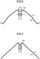
- FIG. 6 is a sectional view illustrating a reflecting member included in an irradiation device of a second variation.
- FIG. 7 is a sectional view illustrating a reflecting member included in an irradiation device of a third variation.
- FIG. 8 is a sectional view illustrating a reflecting member included in an irradiation device of a fourth variation.
- the first and second variations are different from the embodiment in the shape of a projecting section.
- the third variation is different from the embodiment in the shape of a reflection surface.
- the fourth variation is different from the embodiment in the shapes of a reflection surface and a projecting section.
- a reflecting member 21A of the first variation includes a curved reflection surface 23A that reflects light of the lamp 10.
- a projecting section 24A projecting toward the lamp 10, is provided in a position where the distance between the lamp 10 and the reflection surface 23A is the smallest.
- the projecting section 24A is formed in an arcuate shape in section when viewed from the center axis direction of the lamp 10.
- a reflecting member 21B of the second variation includes a curved reflection surface 23B that reflects light of the lamp 10.
- a projecting section 24B projecting toward the lamp 10, is provided in a position where the distance between the lamp 10 and the reflection surface 23B is the smallest.
- the projecting section 24B is formed in a rectangular shape in section when viewed from the center axis direction of the lamp 10.
- the projecting section 24B includes a plane opposed to the lamp 10. Surface treatment for reducing reflectance or a reflection preventing film, may be applied to the plane.
- a reflecting member 21C of the third variation includes a planar reflection surface 23C that reflects light of the lamp 10.
- a projecting section 24C projecting toward the lamp 10, is provided in a position where the distance between the lamp 10 and the reflection surface 23C is the smallest.
- the projecting section 24C is formed in a V-shape in section when viewed from the center axis direction of the lamp 10.
- a reflecting member 21D of the fourth variation two reflection surfaces 23D that reflect light of the lamp 10 are continuously formed.
- the two reflection surfaces 23D are disposed side by side along an irradiation surface in a direction orthogonal to the center axis of the lamp 10.
- a projecting section 24D, projecting toward the lamp 10, is provided between the two reflection surfaces 23D.
- the projecting section 24D is formed in a substantial V-shape in section when viewed from the center axis direction of the lamp 10.
- the irradiation device includes one lamp 10.
- the irradiation device may include a plurality of lamps and a reflecting member that reflects lights of the plurality of lamps.
- projecting sections are respectively provided in positions opposed to the lamps on the reflection surface.
- the projecting section is provided only in an upper part where the reflection surface and the lamp are close to each other.
- the reflection surface is not limited to the reflection surface including one projecting section.
- projecting sections may be respectively provided in a plurality of positions where the reflection surface and the lamp are close to each other.
Landscapes
- Non-Portable Lighting Devices Or Systems Thereof (AREA)
- Electric Stoves And Ranges (AREA)
Abstract
Description
- Embodiments described herein relate generally to an irradiation device.
- As an irradiation device, there is known, for example, an electric stove including a reflecting member that reflects light, which is an infrared ray, irradiated from the entire region in the circumferential direction of a linear halogen lamp to condense the light on a desired irradiation surface side. As the irradiation device of this type, there is also known an irradiation device that includes an ultraviolet lamp as a lamp and that reflects, with the reflecting member, an ultraviolet ray irradiated from the ultraviolet lamp.
- Incidentally, in the irradiation device, a part of the light reflected on the reflecting member returns to the lamp. Therefore, in the irradiation device including the halogen lamp, it is likely that the infrared ray, reflected on the reflecting member, is made incident on the halogen lamp to cause a rise in the temperature of the halogen lamp and to cause blackening, a swell, deformation, and a crack occur in the halogen lamp. Similarly, in the irradiation device including the ultraviolet lamp, since the ultraviolet ray, reflected on the reflecting member, is made incident on the lamp, there is an inconvenience in that a part of the ultraviolet ray is absorbed by the ultraviolet lamp and irradiation efficiency of the ultraviolet ray is deteriorated.
- Therefore, an object of the invention is to provide an irradiation device that can suppress light of a lamp, reflected on a reflecting member, from being made incident on the lamp.
-
-
FIG. 1 is a schematic view illustrating an irradiation device according to an embodiment from the front side; -
FIG. 2 is an A-A sectional view inFIG. 1 ; -
FIG. 3 is a diagram illustrating a simulation result of a reflection state of light; -
FIG. 4 is a diagram illustrating a simulation result of a reflection state of light of a lamp in an irradiation device of a comparative mode; -
FIG. 5 is a sectional view illustrating a reflecting member included in an irradiation device of a first variation; -
FIG. 6 is a sectional view illustrating a reflecting member included in an irradiation device of a second variation; -
FIG. 7 is a sectional view illustrating a reflecting member included in an irradiation device of a third variation; and -
FIG. 8 is a sectional view illustrating a reflecting member included in an irradiation device of a fourth variation. - An
irradiation device 1 according to an embodiment described below includes a linear lamp, a reflecting member, and a projecting section. The lamp emits invisible light. The reflecting member is provided along the circumferential direction of the lamp. The reflecting member includes a reflection surface that reflects the light of the lamp. The projecting section projects toward the outer circumferential surface of the lamp from the reflection surface. The projecting section reflects the light, which is irradiated from the lamp, toward the reflection surface. - The projecting section in the irradiation device, according to the embodiment described below, is formed in a V-shape in a cross section orthogonal to the center axis of the lamp. When the diameter of the lamp is represented as D, width W of the projecting section with respect to the radial direction of the lamp is 0.5D or more and 1.5D or less.
- In the irradiation device according to the embodiment described below, the reflection surface of the reflecting member has an axis of symmetry that passes the center axis of the lamp, on the cross section orthogonal to the center axis of the lamp. The projecting section is located on the axis of symmetry and is provided along the center axis of the lamp.
- The lamp in the irradiation device, according to the embodiment described below, is a halogen lamp.
- The lamp in the irradiation device, according to the embodiment described below, is an ultraviolet lamp.
- The irradiation device, according to the embodiment, is described with reference to the drawings.
FIG. 1 is a schematic view illustrating the irradiation device according to the embodiment from the front side.FIG. 2 is an A-A sectional view inFIG. 1 illustrating the irradiation device according to the embodiment. - As illustrated in
FIGS 1 and2 , theirradiation device 1 according to the embodiment includes alinear lamp 10 that emits invisible light, and a reflectingmember 11 that reflects the light of thelamp 10. Theirradiation device 1 includes a pair ofcap members 12 that is connected to terminals (not illustrated in the figure) provided at both ends of thelamp 10. Thecap members 12 are electrically connected to a not-illustrated power supply section. - As the
lamp 10, for example, a halogen lamp that emits an infrared ray serving as invisible light or an ultraviolet lamp that emits an ultraviolet ray serving as invisible light. As the halogen lamp, a lamp having a diameter of approximately 10 (mm) is used. As the UV lamp, a lamp having a diameter of approximately 15 (mm) to 40 (mm) is used. - When the halogen lamp is used as the
lamp 10, theirradiation device 1 is configured as, for example, a heating appliance used outdoors or the like, a so-called far-infrared electric heater. Theirradiation device 1, including the halogen lamp, may be configured as, for example, a heater for heating PET resin (polyethylene terephthalate) in manufacturing processes of various molded products in which the PET resin is used. When the ultraviolet lamp is used as thelamp 10, theirradiation device 1 is configured as, for example, an irradiating unit that irradiates an ultraviolet ray on a liquid crystal substrate in a manufacturing process of a liquid crystal panel. - For example, the reflecting
member 11 is formed by curving a metal plate and is provided along the circumferential direction of thelamp 10. The reflectingmember 11 has, for example, an elliptical orparabolic reflection surface 13. The reflectingmember 11 includes aprojecting section 14 that projects toward thelamp 10 from thereflection surface 13. Thereflection surface 13 of the reflectingmember 11 has an axis of symmetry that passes the center axis of thelamp 10, on a cross section orthogonal to the center axis of thelamp 10. Theprojecting section 14 is located on the axis of symmetry and is provided along the center axis of thelamp 10. Thereflection surface 13 forms a curve such as a parabola on the cross section orthogonal to the center axis of thelamp 10. The axis of symmetry of thereflection surface 13 indicates an axis of symmetry connecting a center point in the contour line of theprojecting section 14, both ends of which are in contact with thereflection surface 13, and the center axis of thelamp 10, on the cross section orthogonal to the center axis of thelamp 10. InFIG. 2 , theprojecting section 14 is disposed close to a curved portion in an upper part on the opposite side of an irradiation surface side downward in thereflection surface 13. - The
projecting section 14 is formed in a V-shape with a corner directed to thelamp 10 side on the cross section orthogonal to the center axis of thelamp 10. Theprojecting section 14 includes a pair of reflection surfaces forbypass 14a that reflects light, irradiated upward from thelamp 10, toward thereflection surface 13. The projectingsection 14 is provided along the longitudinal direction of thelamp 10 on thereflection surface 13. An angle, formed by the pair of reflection surfaces forbypass 14a in the embodiment, is set to, for example, approximately 90 (°). However, the angle is not limited. - As illustrated in
FIG. 2 , when the diameter of thelamp 10 is represented as D (mm), width W (mm) of theprojecting section 14 with respect to the radial direction of thelamp 10, is formed in a range of 0.5D (mm) or more and 1.5D (mm) or less when viewed from the center axis direction of thelamp 10. Since the width W of theprojecting section 14 is formed in this range, it is possible to properly suppress light of thelamp 10 made incident on thelamp 10. - When the width W of the
projecting section 14 is less than 0.5D, the width W is undesirable because the effect of suppressing the light of thelamp 10, reflected on theprojecting section 14, from being made incident on thelamp 10, cannot be sufficiently obtained. When the width W of theprojecting section 14 exceeds 1.5D, the width W is undesirable because a light distribution property and a light amount of light reflected on thereflection surface 13 of the reflectingmember 11, are less easily obtained properly. More specifically, for example, the light of thelamp 10, reflected on the reflectingmember 11, is easily diffused or the light of thelamp 10, reflected on the reflectingmember 11, is less easily condensed in a desired irradiation range. Therefore, the width W is undesirable because a desired light distribution property and a desired light amount are less easily obtained. - The width W of the
projecting section 14 is set as appropriate according to reflection conditions such as the shape of theprojecting section 14 and the distance between theprojecting section 14 and thelamp 10. In the embodiment, the width W of the projectingsection 14, an angle formed by the reflection surfaces forbypass 14a of which is approximately 90 (°), is set to approximately 0.8D. Behavior of reflected light by the reflecting member of the irradiation device -
FIG. 3 is a diagram illustrating a simulation result of a reflection state of light of thelamp 10 in theirradiation device 1 of the embodiment.FIG. 4 is a diagram illustrating a simulation result of a reflection state of light of thelamp 10 in an irradiation device of a comparative mode. InFIGS 3 and4 , for convenience of simple illustration of a reflection state of light of thelamp 10 reflected on the reflectingmember 11, only light irradiated from an upper semicircular portion in a circular cross section of thelamp 10 when viewed from the center axis direction of thelamp 10 is illustrated. In the embodiment and the comparative mode, the shapes of thelamp 10 and thereflection surface 13 of the reflectingmember 11 are formed the same except presence or absence of the projectingsection 14. - First, a reflection state of light of the
lamp 10 in the comparative mode is described. As illustrated inFIG. 4 , in anirradiation device 101 of the comparative mode, light, irradiated upward from thelamp 10, is reflected in a curved portion in an upper part of the reflectingmember 11. The reflected light is irradiated toward thelamp 10. In this way, in theirradiation device 101 of the comparative mode, the light of thelamp 10, reflected on the reflectingmember 11, is made incident on thelamp 10. This causes deterioration of the halogen lamp or deterioration in irradiation efficiency of the ultraviolet lamp. - On the other hand, in the
irradiation device 1 of the embodiment, as illustrated inFIG. 3 , light, irradiated upward from thelamp 10, is reflected on the reflection surfaces forbypass 14a of the projectingsection 14 in the upper part of the reflectingmember 11. The reflected light travels toward thereflection surface 13. Therefore, a part of the light of thelamp 10, reflected on the reflection surfaces forbypass 14a of the projectingsection 14, travels downward and is irradiated in a desired irradiation range. In this way, the reflectingmember 11 reflects, with the reflection surfaces forbypass 14a of the projectingsection 14, the light, irradiated upward from thelamp 10, to the irradiation surface side to avoid incidence on thelamp 10. - In other words, in the
irradiation device 1 of the embodiment, the light of thelamp 10, reflected on the projectingsection 14, bypasses thelamp 10 and is reflected again by thereflection surface 13 to be condensed on the irradiation surface side. Therefore, since the light, irradiated upward from thelamp 10, is reflected in a direction away from thelamp 10 in the radial direction of thelamp 10 by the projectingsection 14, the light is suppressed from being made incident on thelamp 10. In addition, the light of thelamp 10, reflected by the projectingsection 14, is reflected on thereflection surface 13 to be condensed in the irradiation range. Therefore, a decrease in a light amount on the irradiation surface is suppressed. A desired light distribution property is secured. - In the
irradiation device 101 of the comparative mode, when a light amount of the light of thelamp 10, reflected on the reflectingmember 11 and made incident on thelamp 10, is represented as 1.0, theirradiation device 1 of the embodiment, including the projectingsection 14, can reduce a light amount of the light of thelamp 10, reflected on the reflectingmember 11 and made incident on thelamp 10, to approximately 0.9. - For example, surface treatment may be applied to the projecting
section 14 by blasting, or a reflection preventing film may be provided on the projectingsection 14 according to necessity. The reflectance of the light, irradiated from thelamp 10, may be reduced. Consequently, it is possible to further suppress the light of thelamp 10 made incident on thelamp 10 from the projectingsection 14. However, since a light amount and a light distribution property on the irradiation surface are affected, the reflectance is reduced to secure a proper light amount and a proper light distribution property. - As described above, the
irradiation device 1 of the embodiment includes the reflectingmember 11, which includes thereflection surface 13 that reflects light of thelinear lamp 10 that emits invisible light, and the projectingsection 14 that projects toward the outer circumferential surface of thelamp 10 from thereflection surface 13 and that reflects the light irradiated from thelamp 10 toward thereflection surface 13. Consequently, it is possible to suppress the light of thelamp 10, reflected on the reflectingmember 11, from being made incident on thelamp 10. - The projecting
section 14 of the reflectingmember 11 of theirradiation device 1 of the embodiment is formed in the V-shape on the cross section orthogonal to the center axis of thelamp 10. When the diameter of thelamp 10 is represented as D, the width W of the projectingsection 14 with respect to the radial direction of thelamp 10, is 0.5D or more and 1.5D or less. Consequently, the projectingsection 14 is capable of properly suppressing the light of thelamp 10 made incident on thelamp 10. - In the
irradiation device 1 of the embodiment, thereflection surface 13 of the reflectingmember 11 has the axis of symmetry that passes the center axis of thelamp 10, on the cross section orthogonal to the center axis of thelamp 10. The projectingsection 14 is located on the axis of symmetry and is provided along the center axis of thelamp 10. The light of thelamp 10, made incident on thelamp 10 from thereflection surface 13, can be properly suppressed over the longitudinal direction, which is the center axis direction of thelamp 10. - When the
irradiation device 1 includes the halogen lamp as thelamp 10, an infrared ray, made incident on thelamp 10, can be suppressed by the projectingsection 14. Therefore, it is possible to suppress deterioration such as blackening of the halogen lamp and is possible to suppress a decrease in the life of the halogen lamp. - When the
irradiation device 1 includes the ultraviolet lamp as thelamp 10, an ultraviolet ray, made incident on thelamp 10, can be suppressed by the projectingsection 14. Therefore, it is possible to improve irradiation efficiency of the ultraviolet ray. - The shapes of the reflecting member and the projecting section are not limited to the embodiment. Variations of the reflecting member are described below with reference to the drawings. Note that, in the variations, components same as the components of the embodiment are denoted by the same reference numerals and signs and description of the components is omitted.
-
FIG. 5 is a sectional view illustrating a reflecting member included in an irradiation device of a first variation.FIG. 6 is a sectional view illustrating a reflecting member included in an irradiation device of a second variation.FIG. 7 is a sectional view illustrating a reflecting member included in an irradiation device of a third variation.FIG. 8 is a sectional view illustrating a reflecting member included in an irradiation device of a fourth variation. The first and second variations are different from the embodiment in the shape of a projecting section. The third variation is different from the embodiment in the shape of a reflection surface. The fourth variation is different from the embodiment in the shapes of a reflection surface and a projecting section. - As illustrated in
FIG. 5 , a reflectingmember 21A of the first variation includes acurved reflection surface 23A that reflects light of thelamp 10. On thereflection surface 23A, a projectingsection 24A, projecting toward thelamp 10, is provided in a position where the distance between thelamp 10 and thereflection surface 23A is the smallest. The projectingsection 24A is formed in an arcuate shape in section when viewed from the center axis direction of thelamp 10. - As illustrated in
FIG. 6 , a reflectingmember 21B of the second variation includes acurved reflection surface 23B that reflects light of thelamp 10. On thereflection surface 23B, a projectingsection 24B, projecting toward thelamp 10, is provided in a position where the distance between thelamp 10 and thereflection surface 23B is the smallest. The projectingsection 24B is formed in a rectangular shape in section when viewed from the center axis direction of thelamp 10. The projectingsection 24B includes a plane opposed to thelamp 10. Surface treatment for reducing reflectance or a reflection preventing film, may be applied to the plane. - As illustrated in
FIG. 7 , a reflectingmember 21C of the third variation includes aplanar reflection surface 23C that reflects light of thelamp 10. On thereflection surface 23C, a projectingsection 24C, projecting toward thelamp 10, is provided in a position where the distance between thelamp 10 and thereflection surface 23C is the smallest. The projectingsection 24C is formed in a V-shape in section when viewed from the center axis direction of thelamp 10. - As illustrated in
FIG. 8 , in a reflectingmember 21D of the fourth variation, tworeflection surfaces 23D that reflect light of thelamp 10 are continuously formed. The tworeflection surfaces 23D are disposed side by side along an irradiation surface in a direction orthogonal to the center axis of thelamp 10. A projectingsection 24D, projecting toward thelamp 10, is provided between the tworeflection surfaces 23D. The projectingsection 24D is formed in a substantial V-shape in section when viewed from the center axis direction of thelamp 10. - As described above, in the first to fourth variations, as in the embodiment, it is possible to suppress the light of the
lamp 10, reflected on the reflectingmembers lamp 10. - Note that, in the embodiment and the variations, the irradiation device includes one
lamp 10. However, the irradiation device may include a plurality of lamps and a reflecting member that reflects lights of the plurality of lamps. When the irradiation device includes the plurality of lamps, for each of the lamps, projecting sections are respectively provided in positions opposed to the lamps on the reflection surface. In the embodiment and the variations, the projecting section is provided only in an upper part where the reflection surface and the lamp are close to each other. However, the reflection surface is not limited to the reflection surface including one projecting section. In the reflecting member, according to the shapes and the like of the reflection surface, projecting sections may be respectively provided in a plurality of positions where the reflection surface and the lamp are close to each other. However, from the viewpoint of securing reflection efficiency on the entire reflection surface of the reflecting member, it is favorable to provide one projecting section in a position where the reflection surface and the lamp are close to each other. - While certain embodiments have been described, these embodiments have been presented by way of example only, and are not intended to limit the scope of the inventions. Indeed, the novel embodiments described herein may be embodied in a variety of other forms; furthermore, various omissions, substitutions and changes in the form of the embodiments described herein may be made without departing from the spirit of the inventions. The accompanying claims and their equivalents are intended to cover such forms or modifications as would fall within the scope and spirit of the inventions.
Claims (5)
- An irradiation device comprising:a linear lamp that emits invisible light;a reflecting member that is provided along a circumferential direction of the lamp and that includes a reflection surface, which reflects the light of the lamp; anda projecting section that projects toward an outer circumferential surface of the lamp from the reflection surface and that reflects the light irradiated from the lamp toward the reflection surface.
- The device according to claim 1, wherein
the projecting section is formed in a V-shape on a cross section orthogonal to a center axis of the lamp, and
when a diameter of the lamp is represented as D, width W of the projecting section with respect to a radial direction of the lamp is 0.5D or more and 1.5D or less. - The device according to claim 1 or 2, wherein
the reflection surface of the reflecting member has an axis of symmetry that passes the center axis of the lamp, on the cross section orthogonal to the center axis of the lamp ,and
the projecting section is located on the axis of symmetry and is provided along the center axis. - The device according to any one of claims 1 to 3, wherein the lamp is a halogen lamp.
- The device according to any one of claims 1 to 3, wherein the lamp is an ultraviolet lamp.
Applications Claiming Priority (1)
| Application Number | Priority Date | Filing Date | Title |
|---|---|---|---|
| JP2016078009A JP2017187251A (en) | 2016-04-08 | 2016-04-08 | Irradiation device |
Publications (2)
| Publication Number | Publication Date |
|---|---|
| EP3229555A1 true EP3229555A1 (en) | 2017-10-11 |
| EP3229555B1 EP3229555B1 (en) | 2021-10-13 |
Family
ID=58360827
Family Applications (1)
| Application Number | Title | Priority Date | Filing Date |
|---|---|---|---|
| EP17160541.3A Not-in-force EP3229555B1 (en) | 2016-04-08 | 2017-03-13 | Irradiation device |
Country Status (2)
| Country | Link |
|---|---|
| EP (1) | EP3229555B1 (en) |
| JP (1) | JP2017187251A (en) |
Citations (2)
| Publication number | Priority date | Publication date | Assignee | Title |
|---|---|---|---|---|
| DE10254277A1 (en) * | 2002-11-20 | 2004-06-03 | Wella Ag | Infrared heat radiating unit has an arrangement of V and W-shaped reflectors on either side of an infrared radiation source that are configured to generate an even head radiation output |
| US20070110413A1 (en) * | 2003-11-20 | 2007-05-17 | Matsushita Electric Industrial Co., Ltd. | Infrared ray lamp and heating apparatus |
-
2016
- 2016-04-08 JP JP2016078009A patent/JP2017187251A/en active Pending
-
2017
- 2017-03-13 EP EP17160541.3A patent/EP3229555B1/en not_active Not-in-force
Patent Citations (2)
| Publication number | Priority date | Publication date | Assignee | Title |
|---|---|---|---|---|
| DE10254277A1 (en) * | 2002-11-20 | 2004-06-03 | Wella Ag | Infrared heat radiating unit has an arrangement of V and W-shaped reflectors on either side of an infrared radiation source that are configured to generate an even head radiation output |
| US20070110413A1 (en) * | 2003-11-20 | 2007-05-17 | Matsushita Electric Industrial Co., Ltd. | Infrared ray lamp and heating apparatus |
Also Published As
| Publication number | Publication date |
|---|---|
| JP2017187251A (en) | 2017-10-12 |
| EP3229555B1 (en) | 2021-10-13 |
Similar Documents
| Publication | Publication Date | Title |
|---|---|---|
| US10400992B2 (en) | Lighting apparatus having different reflection sheets | |
| US20160061387A1 (en) | Illuminating device | |
| CN104976585A (en) | Strip-shaped spreadlight lens and LED strip light | |
| JP5788966B2 (en) | Lighting fixture with cover panel | |
| US9388957B2 (en) | Secondary optical element and light source module | |
| EP3229555B1 (en) | Irradiation device | |
| CN107548171A (en) | Infrared heater | |
| US10801695B2 (en) | Lamp | |
| KR102388796B1 (en) | Lighting apparatus | |
| CN108698078B (en) | Ultraviolet curing device with split ultraviolet deflection mirror | |
| US20160209113A1 (en) | Uv light curing systems, and methods of designing and operating the same | |
| US20080031603A1 (en) | Infrared heater | |
| US20180313518A1 (en) | Optical device | |
| US20140268813A1 (en) | Lighting device with virtual light source | |
| CN105137581B (en) | Optical lens and light-emitting device using same | |
| CN105444114B (en) | Reflector and LED lighting device using the reflector | |
| KR101604667B1 (en) | Diffusion lens backlight unit | |
| JP5702800B2 (en) | Electric reflector lamp and reflector | |
| CN106111493B (en) | Cure lamp | |
| CN104075253A (en) | Irradiation device | |
| JP7580079B2 (en) | Heating unit and heating device | |
| CN105785490A (en) | Light irradiation device | |
| KR101413631B1 (en) | A reflection cover for fluorescent lamp | |
| CN110848638B (en) | Optical device capable of emitting light at small angle and implementation method thereof | |
| CN108224365A (en) | Planar insertion type L ED reflector |
Legal Events
| Date | Code | Title | Description |
|---|---|---|---|
| PUAI | Public reference made under article 153(3) epc to a published international application that has entered the european phase |
Free format text: ORIGINAL CODE: 0009012 |
|
| STAA | Information on the status of an ep patent application or granted ep patent |
Free format text: STATUS: THE APPLICATION HAS BEEN PUBLISHED |
|
| AK | Designated contracting states |
Kind code of ref document: A1 Designated state(s): AL AT BE BG CH CY CZ DE DK EE ES FI FR GB GR HR HU IE IS IT LI LT LU LV MC MK MT NL NO PL PT RO RS SE SI SK SM TR |
|
| AX | Request for extension of the european patent |
Extension state: BA ME |
|
| STAA | Information on the status of an ep patent application or granted ep patent |
Free format text: STATUS: REQUEST FOR EXAMINATION WAS MADE |
|
| 17P | Request for examination filed |
Effective date: 20180316 |
|
| RBV | Designated contracting states (corrected) |
Designated state(s): AL AT BE BG CH CY CZ DE DK EE ES FI FR GB GR HR HU IE IS IT LI LT LU LV MC MK MT NL NO PL PT RO RS SE SI SK SM TR |
|
| STAA | Information on the status of an ep patent application or granted ep patent |
Free format text: STATUS: EXAMINATION IS IN PROGRESS |
|
| 17Q | First examination report despatched |
Effective date: 20200122 |
|
| GRAP | Despatch of communication of intention to grant a patent |
Free format text: ORIGINAL CODE: EPIDOSNIGR1 |
|
| STAA | Information on the status of an ep patent application or granted ep patent |
Free format text: STATUS: GRANT OF PATENT IS INTENDED |
|
| INTG | Intention to grant announced |
Effective date: 20210525 |
|
| GRAS | Grant fee paid |
Free format text: ORIGINAL CODE: EPIDOSNIGR3 |
|
| GRAA | (expected) grant |
Free format text: ORIGINAL CODE: 0009210 |
|
| STAA | Information on the status of an ep patent application or granted ep patent |
Free format text: STATUS: THE PATENT HAS BEEN GRANTED |
|
| AK | Designated contracting states |
Kind code of ref document: B1 Designated state(s): AL AT BE BG CH CY CZ DE DK EE ES FI FR GB GR HR HU IE IS IT LI LT LU LV MC MK MT NL NO PL PT RO RS SE SI SK SM TR |
|
| REG | Reference to a national code |
Ref country code: GB Ref legal event code: FG4D |
|
| REG | Reference to a national code |
Ref country code: CH Ref legal event code: EP |
|
| REG | Reference to a national code |
Ref country code: DE Ref legal event code: R096 Ref document number: 602017047440 Country of ref document: DE |
|
| REG | Reference to a national code |
Ref country code: IE Ref legal event code: FG4D |
|
| REG | Reference to a national code |
Ref country code: AT Ref legal event code: REF Ref document number: 1439117 Country of ref document: AT Kind code of ref document: T Effective date: 20211115 |
|
| REG | Reference to a national code |
Ref country code: DE Ref legal event code: R084 Ref document number: 602017047440 Country of ref document: DE |
|
| REG | Reference to a national code |
Ref country code: LT Ref legal event code: MG9D |
|
| REG | Reference to a national code |
Ref country code: NL Ref legal event code: MP Effective date: 20211013 |
|
| REG | Reference to a national code |
Ref country code: AT Ref legal event code: MK05 Ref document number: 1439117 Country of ref document: AT Kind code of ref document: T Effective date: 20211013 |
|
| REG | Reference to a national code |
Ref country code: GB Ref legal event code: 746 Effective date: 20220307 |
|
| PG25 | Lapsed in a contracting state [announced via postgrant information from national office to epo] |
Ref country code: RS Free format text: LAPSE BECAUSE OF FAILURE TO SUBMIT A TRANSLATION OF THE DESCRIPTION OR TO PAY THE FEE WITHIN THE PRESCRIBED TIME-LIMIT Effective date: 20211013 Ref country code: LT Free format text: LAPSE BECAUSE OF FAILURE TO SUBMIT A TRANSLATION OF THE DESCRIPTION OR TO PAY THE FEE WITHIN THE PRESCRIBED TIME-LIMIT Effective date: 20211013 Ref country code: FI Free format text: LAPSE BECAUSE OF FAILURE TO SUBMIT A TRANSLATION OF THE DESCRIPTION OR TO PAY THE FEE WITHIN THE PRESCRIBED TIME-LIMIT Effective date: 20211013 Ref country code: BG Free format text: LAPSE BECAUSE OF FAILURE TO SUBMIT A TRANSLATION OF THE DESCRIPTION OR TO PAY THE FEE WITHIN THE PRESCRIBED TIME-LIMIT Effective date: 20220113 Ref country code: AT Free format text: LAPSE BECAUSE OF FAILURE TO SUBMIT A TRANSLATION OF THE DESCRIPTION OR TO PAY THE FEE WITHIN THE PRESCRIBED TIME-LIMIT Effective date: 20211013 |
|
| PG25 | Lapsed in a contracting state [announced via postgrant information from national office to epo] |
Ref country code: IS Free format text: LAPSE BECAUSE OF FAILURE TO SUBMIT A TRANSLATION OF THE DESCRIPTION OR TO PAY THE FEE WITHIN THE PRESCRIBED TIME-LIMIT Effective date: 20220213 Ref country code: SE Free format text: LAPSE BECAUSE OF FAILURE TO SUBMIT A TRANSLATION OF THE DESCRIPTION OR TO PAY THE FEE WITHIN THE PRESCRIBED TIME-LIMIT Effective date: 20211013 Ref country code: PT Free format text: LAPSE BECAUSE OF FAILURE TO SUBMIT A TRANSLATION OF THE DESCRIPTION OR TO PAY THE FEE WITHIN THE PRESCRIBED TIME-LIMIT Effective date: 20220214 Ref country code: PL Free format text: LAPSE BECAUSE OF FAILURE TO SUBMIT A TRANSLATION OF THE DESCRIPTION OR TO PAY THE FEE WITHIN THE PRESCRIBED TIME-LIMIT Effective date: 20211013 Ref country code: NO Free format text: LAPSE BECAUSE OF FAILURE TO SUBMIT A TRANSLATION OF THE DESCRIPTION OR TO PAY THE FEE WITHIN THE PRESCRIBED TIME-LIMIT Effective date: 20220113 Ref country code: NL Free format text: LAPSE BECAUSE OF FAILURE TO SUBMIT A TRANSLATION OF THE DESCRIPTION OR TO PAY THE FEE WITHIN THE PRESCRIBED TIME-LIMIT Effective date: 20211013 Ref country code: LV Free format text: LAPSE BECAUSE OF FAILURE TO SUBMIT A TRANSLATION OF THE DESCRIPTION OR TO PAY THE FEE WITHIN THE PRESCRIBED TIME-LIMIT Effective date: 20211013 Ref country code: HR Free format text: LAPSE BECAUSE OF FAILURE TO SUBMIT A TRANSLATION OF THE DESCRIPTION OR TO PAY THE FEE WITHIN THE PRESCRIBED TIME-LIMIT Effective date: 20211013 Ref country code: GR Free format text: LAPSE BECAUSE OF FAILURE TO SUBMIT A TRANSLATION OF THE DESCRIPTION OR TO PAY THE FEE WITHIN THE PRESCRIBED TIME-LIMIT Effective date: 20220114 Ref country code: ES Free format text: LAPSE BECAUSE OF FAILURE TO SUBMIT A TRANSLATION OF THE DESCRIPTION OR TO PAY THE FEE WITHIN THE PRESCRIBED TIME-LIMIT Effective date: 20211013 |
|
| REG | Reference to a national code |
Ref country code: DE Ref legal event code: R097 Ref document number: 602017047440 Country of ref document: DE |
|
| PG25 | Lapsed in a contracting state [announced via postgrant information from national office to epo] |
Ref country code: SM Free format text: LAPSE BECAUSE OF FAILURE TO SUBMIT A TRANSLATION OF THE DESCRIPTION OR TO PAY THE FEE WITHIN THE PRESCRIBED TIME-LIMIT Effective date: 20211013 Ref country code: SK Free format text: LAPSE BECAUSE OF FAILURE TO SUBMIT A TRANSLATION OF THE DESCRIPTION OR TO PAY THE FEE WITHIN THE PRESCRIBED TIME-LIMIT Effective date: 20211013 Ref country code: RO Free format text: LAPSE BECAUSE OF FAILURE TO SUBMIT A TRANSLATION OF THE DESCRIPTION OR TO PAY THE FEE WITHIN THE PRESCRIBED TIME-LIMIT Effective date: 20211013 Ref country code: EE Free format text: LAPSE BECAUSE OF FAILURE TO SUBMIT A TRANSLATION OF THE DESCRIPTION OR TO PAY THE FEE WITHIN THE PRESCRIBED TIME-LIMIT Effective date: 20211013 Ref country code: DK Free format text: LAPSE BECAUSE OF FAILURE TO SUBMIT A TRANSLATION OF THE DESCRIPTION OR TO PAY THE FEE WITHIN THE PRESCRIBED TIME-LIMIT Effective date: 20211013 Ref country code: CZ Free format text: LAPSE BECAUSE OF FAILURE TO SUBMIT A TRANSLATION OF THE DESCRIPTION OR TO PAY THE FEE WITHIN THE PRESCRIBED TIME-LIMIT Effective date: 20211013 |
|
| PLBE | No opposition filed within time limit |
Free format text: ORIGINAL CODE: 0009261 |
|
| STAA | Information on the status of an ep patent application or granted ep patent |
Free format text: STATUS: NO OPPOSITION FILED WITHIN TIME LIMIT |
|
| 26N | No opposition filed |
Effective date: 20220714 |
|
| PG25 | Lapsed in a contracting state [announced via postgrant information from national office to epo] |
Ref country code: MC Free format text: LAPSE BECAUSE OF FAILURE TO SUBMIT A TRANSLATION OF THE DESCRIPTION OR TO PAY THE FEE WITHIN THE PRESCRIBED TIME-LIMIT Effective date: 20211013 Ref country code: AL Free format text: LAPSE BECAUSE OF FAILURE TO SUBMIT A TRANSLATION OF THE DESCRIPTION OR TO PAY THE FEE WITHIN THE PRESCRIBED TIME-LIMIT Effective date: 20211013 |
|
| REG | Reference to a national code |
Ref country code: CH Ref legal event code: PL |
|
| PG25 | Lapsed in a contracting state [announced via postgrant information from national office to epo] |
Ref country code: SI Free format text: LAPSE BECAUSE OF FAILURE TO SUBMIT A TRANSLATION OF THE DESCRIPTION OR TO PAY THE FEE WITHIN THE PRESCRIBED TIME-LIMIT Effective date: 20211013 |
|
| REG | Reference to a national code |
Ref country code: BE Ref legal event code: MM Effective date: 20220331 |
|
| PG25 | Lapsed in a contracting state [announced via postgrant information from national office to epo] |
Ref country code: LU Free format text: LAPSE BECAUSE OF NON-PAYMENT OF DUE FEES Effective date: 20220313 Ref country code: LI Free format text: LAPSE BECAUSE OF NON-PAYMENT OF DUE FEES Effective date: 20220331 Ref country code: IE Free format text: LAPSE BECAUSE OF NON-PAYMENT OF DUE FEES Effective date: 20220313 Ref country code: CH Free format text: LAPSE BECAUSE OF NON-PAYMENT OF DUE FEES Effective date: 20220331 |
|
| PGFP | Annual fee paid to national office [announced via postgrant information from national office to epo] |
Ref country code: FR Payment date: 20221220 Year of fee payment: 7 |
|
| PG25 | Lapsed in a contracting state [announced via postgrant information from national office to epo] |
Ref country code: BE Free format text: LAPSE BECAUSE OF NON-PAYMENT OF DUE FEES Effective date: 20220331 |
|
| PG25 | Lapsed in a contracting state [announced via postgrant information from national office to epo] |
Ref country code: IT Free format text: LAPSE BECAUSE OF FAILURE TO SUBMIT A TRANSLATION OF THE DESCRIPTION OR TO PAY THE FEE WITHIN THE PRESCRIBED TIME-LIMIT Effective date: 20211013 |
|
| PGFP | Annual fee paid to national office [announced via postgrant information from national office to epo] |
Ref country code: DE Payment date: 20221220 Year of fee payment: 7 |
|
| PG25 | Lapsed in a contracting state [announced via postgrant information from national office to epo] |
Ref country code: HU Free format text: LAPSE BECAUSE OF FAILURE TO SUBMIT A TRANSLATION OF THE DESCRIPTION OR TO PAY THE FEE WITHIN THE PRESCRIBED TIME-LIMIT; INVALID AB INITIO Effective date: 20170313 |
|
| PG25 | Lapsed in a contracting state [announced via postgrant information from national office to epo] |
Ref country code: MK Free format text: LAPSE BECAUSE OF FAILURE TO SUBMIT A TRANSLATION OF THE DESCRIPTION OR TO PAY THE FEE WITHIN THE PRESCRIBED TIME-LIMIT Effective date: 20211013 Ref country code: CY Free format text: LAPSE BECAUSE OF FAILURE TO SUBMIT A TRANSLATION OF THE DESCRIPTION OR TO PAY THE FEE WITHIN THE PRESCRIBED TIME-LIMIT Effective date: 20211013 |
|
| PGFP | Annual fee paid to national office [announced via postgrant information from national office to epo] |
Ref country code: GB Payment date: 20240105 Year of fee payment: 8 |
|
| PG25 | Lapsed in a contracting state [announced via postgrant information from national office to epo] |
Ref country code: TR Free format text: LAPSE BECAUSE OF FAILURE TO SUBMIT A TRANSLATION OF THE DESCRIPTION OR TO PAY THE FEE WITHIN THE PRESCRIBED TIME-LIMIT Effective date: 20211013 |
|
| PG25 | Lapsed in a contracting state [announced via postgrant information from national office to epo] |
Ref country code: MT Free format text: LAPSE BECAUSE OF FAILURE TO SUBMIT A TRANSLATION OF THE DESCRIPTION OR TO PAY THE FEE WITHIN THE PRESCRIBED TIME-LIMIT Effective date: 20211013 |
|
| REG | Reference to a national code |
Ref country code: DE Ref legal event code: R119 Ref document number: 602017047440 Country of ref document: DE |
|
| PG25 | Lapsed in a contracting state [announced via postgrant information from national office to epo] |
Ref country code: DE Free format text: LAPSE BECAUSE OF NON-PAYMENT OF DUE FEES Effective date: 20241001 |
|
| PG25 | Lapsed in a contracting state [announced via postgrant information from national office to epo] |
Ref country code: FR Free format text: LAPSE BECAUSE OF NON-PAYMENT OF DUE FEES Effective date: 20240331 |
|
| PG25 | Lapsed in a contracting state [announced via postgrant information from national office to epo] |
Ref country code: FR Free format text: LAPSE BECAUSE OF NON-PAYMENT OF DUE FEES Effective date: 20240331 Ref country code: DE Free format text: LAPSE BECAUSE OF NON-PAYMENT OF DUE FEES Effective date: 20241001 |
|
| GBPC | Gb: european patent ceased through non-payment of renewal fee |
Effective date: 20250313 |
|
| PG25 | Lapsed in a contracting state [announced via postgrant information from national office to epo] |
Ref country code: GB Free format text: LAPSE BECAUSE OF NON-PAYMENT OF DUE FEES Effective date: 20250313 |