EP3229433B1 - Procédé pour transmettre/recevoir une unité de données de protocole physique (ppdu) dans un système de communication sans fil et appareil associé - Google Patents
Procédé pour transmettre/recevoir une unité de données de protocole physique (ppdu) dans un système de communication sans fil et appareil associé Download PDFInfo
- Publication number
- EP3229433B1 EP3229433B1 EP15864589.5A EP15864589A EP3229433B1 EP 3229433 B1 EP3229433 B1 EP 3229433B1 EP 15864589 A EP15864589 A EP 15864589A EP 3229433 B1 EP3229433 B1 EP 3229433B1
- Authority
- EP
- European Patent Office
- Prior art keywords
- hes
- tone
- tones
- sequence
- stf
- Prior art date
- Legal status (The legal status is an assumption and is not a legal conclusion. Google has not performed a legal analysis and makes no representation as to the accuracy of the status listed.)
- Active
Links
- 238000000034 method Methods 0.000 title claims description 83
- 238000004891 communication Methods 0.000 title claims description 37
- 230000005540 biological transmission Effects 0.000 claims description 177
- 238000012549 training Methods 0.000 claims description 18
- 238000010586 diagram Methods 0.000 description 27
- 230000004044 response Effects 0.000 description 20
- 101150081243 STA1 gene Proteins 0.000 description 17
- 238000007726 management method Methods 0.000 description 16
- OVGWMUWIRHGGJP-WTODYLRWSA-N (z)-7-[(1r,3s,4s,5r)-3-[(e,3r)-3-hydroxyoct-1-enyl]-6-thiabicyclo[3.1.1]heptan-4-yl]hept-5-enoic acid Chemical compound OC(=O)CCC\C=C/C[C@H]1[C@H](/C=C/[C@H](O)CCCCC)C[C@H]2S[C@@H]1C2 OVGWMUWIRHGGJP-WTODYLRWSA-N 0.000 description 13
- 101100366889 Caenorhabditis elegans sta-2 gene Proteins 0.000 description 13
- VYLDEYYOISNGST-UHFFFAOYSA-N bissulfosuccinimidyl suberate Chemical compound O=C1C(S(=O)(=O)O)CC(=O)N1OC(=O)CCCCCCC(=O)ON1C(=O)C(S(O)(=O)=O)CC1=O VYLDEYYOISNGST-UHFFFAOYSA-N 0.000 description 11
- 230000006872 improvement Effects 0.000 description 10
- 238000005070 sampling Methods 0.000 description 10
- 230000006870 function Effects 0.000 description 9
- 230000007246 mechanism Effects 0.000 description 9
- 230000008569 process Effects 0.000 description 9
- 239000000523 sample Substances 0.000 description 9
- 238000005516 engineering process Methods 0.000 description 7
- 230000000694 effects Effects 0.000 description 5
- 108700026140 MAC combination Proteins 0.000 description 4
- 125000004122 cyclic group Chemical group 0.000 description 4
- 239000012634 fragment Substances 0.000 description 4
- 238000010295 mobile communication Methods 0.000 description 4
- 101100172132 Mus musculus Eif3a gene Proteins 0.000 description 3
- 238000001514 detection method Methods 0.000 description 3
- 230000002441 reversible effect Effects 0.000 description 3
- 230000006978 adaptation Effects 0.000 description 2
- 230000008901 benefit Effects 0.000 description 2
- 230000001419 dependent effect Effects 0.000 description 2
- 239000003999 initiator Substances 0.000 description 2
- 230000004048 modification Effects 0.000 description 2
- 238000012986 modification Methods 0.000 description 2
- 230000010363 phase shift Effects 0.000 description 2
- 238000012545 processing Methods 0.000 description 2
- 230000011664 signaling Effects 0.000 description 2
- 238000001228 spectrum Methods 0.000 description 2
- 230000002123 temporal effect Effects 0.000 description 2
- 238000003491 array Methods 0.000 description 1
- 230000001174 ascending effect Effects 0.000 description 1
- PKOMXLRKGNITKG-UHFFFAOYSA-L calcium;hydroxy(methyl)arsinate Chemical compound [Ca+2].C[As](O)([O-])=O.C[As](O)([O-])=O PKOMXLRKGNITKG-UHFFFAOYSA-L 0.000 description 1
- 230000001413 cellular effect Effects 0.000 description 1
- 230000008859 change Effects 0.000 description 1
- 238000010276 construction Methods 0.000 description 1
- 238000012937 correction Methods 0.000 description 1
- 230000008878 coupling Effects 0.000 description 1
- 238000010168 coupling process Methods 0.000 description 1
- 238000005859 coupling reaction Methods 0.000 description 1
- 238000005562 fading Methods 0.000 description 1
- 230000010354 integration Effects 0.000 description 1
- 230000003993 interaction Effects 0.000 description 1
- 230000007774 longterm Effects 0.000 description 1
- 239000011159 matrix material Substances 0.000 description 1
- 238000013468 resource allocation Methods 0.000 description 1
- 230000008054 signal transmission Effects 0.000 description 1
- 230000001502 supplementing effect Effects 0.000 description 1
- 230000001360 synchronised effect Effects 0.000 description 1
- 238000012546 transfer Methods 0.000 description 1
Images


Classifications
-
- H—ELECTRICITY
- H04—ELECTRIC COMMUNICATION TECHNIQUE
- H04L—TRANSMISSION OF DIGITAL INFORMATION, e.g. TELEGRAPHIC COMMUNICATION
- H04L5/00—Arrangements affording multiple use of the transmission path
- H04L5/003—Arrangements for allocating sub-channels of the transmission path
- H04L5/0044—Arrangements for allocating sub-channels of the transmission path allocation of payload
-
- H—ELECTRICITY
- H04—ELECTRIC COMMUNICATION TECHNIQUE
- H04L—TRANSMISSION OF DIGITAL INFORMATION, e.g. TELEGRAPHIC COMMUNICATION
- H04L27/00—Modulated-carrier systems
- H04L27/26—Systems using multi-frequency codes
- H04L27/2601—Multicarrier modulation systems
- H04L27/2602—Signal structure
- H04L27/261—Details of reference signals
- H04L27/2613—Structure of the reference signals
-
- H—ELECTRICITY
- H04—ELECTRIC COMMUNICATION TECHNIQUE
- H04B—TRANSMISSION
- H04B7/00—Radio transmission systems, i.e. using radiation field
- H04B7/02—Diversity systems; Multi-antenna system, i.e. transmission or reception using multiple antennas
- H04B7/04—Diversity systems; Multi-antenna system, i.e. transmission or reception using multiple antennas using two or more spaced independent antennas
- H04B7/0413—MIMO systems
- H04B7/0452—Multi-user MIMO systems
-
- H—ELECTRICITY
- H04—ELECTRIC COMMUNICATION TECHNIQUE
- H04L—TRANSMISSION OF DIGITAL INFORMATION, e.g. TELEGRAPHIC COMMUNICATION
- H04L27/00—Modulated-carrier systems
- H04L27/26—Systems using multi-frequency codes
-
- H—ELECTRICITY
- H04—ELECTRIC COMMUNICATION TECHNIQUE
- H04L—TRANSMISSION OF DIGITAL INFORMATION, e.g. TELEGRAPHIC COMMUNICATION
- H04L27/00—Modulated-carrier systems
- H04L27/26—Systems using multi-frequency codes
- H04L27/2601—Multicarrier modulation systems
- H04L27/2647—Arrangements specific to the receiver only
- H04L27/2655—Synchronisation arrangements
- H04L27/2657—Carrier synchronisation
- H04L27/2659—Coarse or integer frequency offset determination and synchronisation
-
- H—ELECTRICITY
- H04—ELECTRIC COMMUNICATION TECHNIQUE
- H04L—TRANSMISSION OF DIGITAL INFORMATION, e.g. TELEGRAPHIC COMMUNICATION
- H04L27/00—Modulated-carrier systems
- H04L27/26—Systems using multi-frequency codes
- H04L27/2601—Multicarrier modulation systems
- H04L27/2647—Arrangements specific to the receiver only
- H04L27/2655—Synchronisation arrangements
- H04L27/2662—Symbol synchronisation
- H04L27/2663—Coarse synchronisation, e.g. by correlation
-
- H—ELECTRICITY
- H04—ELECTRIC COMMUNICATION TECHNIQUE
- H04L—TRANSMISSION OF DIGITAL INFORMATION, e.g. TELEGRAPHIC COMMUNICATION
- H04L5/00—Arrangements affording multiple use of the transmission path
- H04L5/0001—Arrangements for dividing the transmission path
- H04L5/0003—Two-dimensional division
- H04L5/0005—Time-frequency
- H04L5/0007—Time-frequency the frequencies being orthogonal, e.g. OFDM(A), DMT
-
- H—ELECTRICITY
- H04—ELECTRIC COMMUNICATION TECHNIQUE
- H04W—WIRELESS COMMUNICATION NETWORKS
- H04W84/00—Network topologies
- H04W84/02—Hierarchically pre-organised networks, e.g. paging networks, cellular networks, WLAN [Wireless Local Area Network] or WLL [Wireless Local Loop]
- H04W84/10—Small scale networks; Flat hierarchical networks
- H04W84/12—WLAN [Wireless Local Area Networks]
-
- H—ELECTRICITY
- H04—ELECTRIC COMMUNICATION TECHNIQUE
- H04L—TRANSMISSION OF DIGITAL INFORMATION, e.g. TELEGRAPHIC COMMUNICATION
- H04L27/00—Modulated-carrier systems
- H04L27/26—Systems using multi-frequency codes
- H04L27/2601—Multicarrier modulation systems
- H04L27/2602—Signal structure
- H04L27/2603—Signal structure ensuring backward compatibility with legacy system
-
- H—ELECTRICITY
- H04—ELECTRIC COMMUNICATION TECHNIQUE
- H04L—TRANSMISSION OF DIGITAL INFORMATION, e.g. TELEGRAPHIC COMMUNICATION
- H04L5/00—Arrangements affording multiple use of the transmission path
- H04L5/003—Arrangements for allocating sub-channels of the transmission path
- H04L5/0053—Allocation of signaling, i.e. of overhead other than pilot signals
Definitions
- the present invention relates to wireless communication systems, and more particularly, to a method for transmitting and receiving single-user (SU) or multi-user (MU) Physical Protocol Data Unit (PPDU) and an apparatus for supporting the same.
- SU single-user
- MU multi-user
- PPDU Physical Protocol Data Unit
- Wi-Fi is a wireless local area network (WLAN) technology which enables a device to access the Internet in a frequency band of 2.4 GHz, 5 GHz or 60 GHz.
- WLAN wireless local area network
- a WLAN is based on the institute of electrical and electronic engineers (IEEE) 802.11 standard.
- IEEE institute of electrical and electronic engineers
- the wireless next generation standing committee (WNG SC) of IEEE 802.11 is an ad-hoc committee which is concerned about the next-generation wireless local area network (WLAN) in the medium to longer term.
- IEEE 802.11n has an object of increasing the speed and reliability of a network and extending the coverage of a wireless network. More specifically, IEEE 802.11n supports a high throughput (HT) providing a maximum data rate of 600 Mbps. Furthermore, in order to minimize a transfer error and to optimize a data rate, IEEE 802.11n is based on a multiple inputs and multiple outputs (MIMO) technology in which multiple antennas are used at both ends of a transmission unit and a reception unit.
- MIMO multiple inputs and multiple outputs
- IEEE 802.11ac As the spread of a WLAN is activated and applications using the WLAN are diversified, in the next-generation WLAN system supporting a very high throughput (VHT), IEEE 802.11ac has been newly enacted as the next version of an IEEE 802.11n WLAN system.
- IEEE 802.11 ac supports a data rate of 1 Gbps or more through 80 MHz bandwidth transmission and/or higher bandwidth transmission (e.g., 160 MHz), and chiefly operates in a 5 GHz band.
- IEEE 802.11ax chiefly discussed in the next-generation WLAN task group called a so-called IEEE 802.11ax or high efficiency (HEW) WLAN includes 1) the improvement of an 802.11 physical (PHY) layer and medium access control (MAC) layer in bands of 2.4 GHz, 5 GHz, etc., 2) the improvement of spectrum efficiency and area throughput, 3) the improvement of performance in actual indoor and outdoor environments, such as an environment in which an interference source is present, a dense heterogeneous network environment, and an environment in which a high user load is present and so on.
- PHY physical
- MAC medium access control
- IEEE 802.11ax A scenario chiefly taken into consideration in IEEE 802.11ax is a dense environment in which many access points (APs) and many stations (STAs) are present.
- APs access points
- STAs stations
- IEEE 802.11ax the improvement of spectrum efficiency and area throughput is discussed in such a situation. More specifically, there is an interest in the improvement of substantial performance in outdoor environments not greatly taken into consideration in existing WLANs in addition to indoor environments.
- IEEE 802.11ax there is a great interest in scenarios, such as wireless offices, smart homes, stadiums, hotspots, and buildings/apartments.
- scenarios such as wireless offices, smart homes, stadiums, hotspots, and buildings/apartments.
- the improvement of system performance in a dense environment in which many APs and many STAs are present is discussed based on the corresponding scenarios.
- IEEE 802.11ax In the future, it is expected in IEEE 802.11ax that the improvement of system performance in an overlapping basic service set (OBSS) environment, the improvement of an outdoor environment, cellular offloading, and so on rather than single link performance improvement in a single basic service set (BSS) will be actively discussed.
- the directivity of such IEEE 802.11ax means that the next-generation WLAN will have a technical scope gradually similar to that of mobile communication.
- D2D direct-to-direct
- US 2014/211775 A1 outlines wireless communications utilizing varying cyclic prefix lengths, varying repetition intervals, and varying symbol durations to ameliorate the effects of large delay spreads.
- WO 2013/033231 A2 describes apparatus and methods for communicating and applying training sequences.
- a short training field (STF) sequence comprising thirty two values or less is generated, the STF sequence can include a first subset of values including zero and non-zero values, the non-zero values can be located at indices of the first subset that are at least a multiple of two, and can be a multiple of four, and the STF sequence includes a second subset of zero values that can include all values not included within the first subset.
- STF short training field
- US 2013/286959 A1 outlines coordinated orthogonal block-based resource allocation (COBRA) operations.
- an access point (AP) is described to be configured to indicate to a plurality of stations (STA)s that it may support COBRA.
- STA stations
- Each WTRU may be configured to indicate to the AP that it can support COBRA as well.
- the AP may be configured to transmit a COBRA controller information element (IE) comprising a plurality of fields to each of the WTRUs.
- Each WTRU may be configured to transmit a COBRA controllee IE comprising a plurality of fields.
- IE COBRA controller information element
- the Greenfield preamble includes a short training field (STF), a first long training field (LTF), a first signal (SIG) field, at least one additional LTF, and a second SIG field.
- STF short training field
- LTF first long training field
- SIG first signal
- WO 2011/130363 A1 outlines construction of a short training field (STF) sequence of a Very High Throughput (VHT) preamble in an effort to reduce a peak-to-average power ratio (PAPR).
- STF sequence is disclosed to have a specific repetition period.
- HE-STF High-Efficiency Short Training Field
- AGC Automatic Gain Control
- an object of the present invention is to propose a method for generating HE-STF frequency domain sequence.
- Another object of the present invention is to propose a method for transmitting and receiving a PPDU that includes an HE-STF field.
- a method for transmitting a Physical Protocol Data Unit (PPDU) performed by an apparatus in a wireless communication system is provided as defined in independent claim 1.
- PPDU Physical Protocol Data Unit
- an apparatus for transmitting a Physical Protocol Data Unit (PPDU) in a wireless communication system is provided as defined in independent claim 4.
- PPDU Physical Protocol Data Unit
- a peak-to-power average ratio (PAPR) with respect to an HE-STF field may be minimized.
- a PPDU that includes an HE-STF field which is configured based on HE-STF sequence may be smoothly transmitted and received at a transmitting/receiving terminal.
- structures or devices which are publicly known may be omitted, or may be depicted as a block diagram centering on the core functions of the structures or the devices.
- CDMA code division multiple access
- FDMA frequency division multiple access
- TDMA time division multiple access
- OFDMA orthogonal frequency division multiple access
- SC-FDMA single carrier frequency division multiple access
- NOMA non-orthogonal multiple access
- CDMA may be implemented using a radio technology, such as universal terrestrial radio access (UTRA) or CDMA2000.
- TDMA may be implemented using a radio technology, such as global system for Mobile communications (GSM)/general packet radio service (GPRS)/enhanced data rates for GSM evolution (EDGE).
- GSM global system for Mobile communications
- GPRS general packet radio service
- EDGE enhanced data rates for GSM evolution
- OFDMA may be implemented using a radio technology, such as institute of electrical and electronics engineers (IEEE) 802.11 (Wi-Fi), IEEE 802.16 (WiMAX), IEEE 802.20, or evolved UTRA (E-UTRA).
- UTRA is part of a universal mobile telecommunications system (UMTS).
- 3 rd generation partnership project (3GPP) long term evolution (LTE) is part of an evolved UMTS (E-UMTS) using evolved UMTS terrestrial radio access (E-UTRA), and it adopts OFDMA in downlink and adopts SC-FDMA in uplink.
- LTE-advanced (LTE-A) is the evolution of 3GPP LTE.
- IEEE 802.11 is chiefly described, but the technical characteristics of the present invention are not limited thereto.
- FIG. 1 is a diagram showing an example of an IEEE 802.11 system to which an embodiment of the present invention may be applied.
- the IEEE 802.11 configuration may include a plurality of elements. There may be provided a wireless communication system supporting transparent station (STA) mobility for a higher layer through an interaction between the elements.
- STA transparent station
- a basic service set (BSS) may correspond to a basic configuration block in an IEEE 802.11 system.
- FIG. 1 illustrates that three BSSs BSS 1 to BSS 3 are present and two STAs (e.g., an STA 1 and an STA 2 are included in the BSS 1, an STA 3 and an STA 4 are included in the BSS 2, and an STA 5 and an STA 6 are included in the BSS 3) are included as the members of each BSS.
- STAs e.g., an STA 1 and an STA 2 are included in the BSS 1
- STA 3 and an STA 4 are included in the BSS 2
- STA 5 and an STA 6 are included in the BSS 3 are included as the members of each BSS.
- an ellipse indicative of a BSS may be interpreted as being indicative of a coverage area in which STAs included in the corresponding BSS maintain communication.
- Such an area may be called a basic service area (BSA).
- BSA basic service area
- an IBSS may have a minimum form including only two STAs.
- the BSS 3 of FIG. 1 which is the simplest form and from which other elements have been omitted may correspond to a representative example of the IBSS.
- STAs can directly communicate with each other.
- a LAN of such a form is not previously planned and configured, but may be configured when it is necessary. This may also be called an ad-hoc network.
- an STA When an STA is powered off or on or an STA enters into or exits from a BSS area, the membership of the STA in the BSS may be dynamically changed. In order to become a member of a BSS, an STA may join the BSS using a synchronization process. In order to access all of services in a BSS-based configuration, an STA needs to be associated with the BSS. Such association may be dynamically configured, and may include the use of a distribution system service (DSS).
- DSS distribution system service
- the distance of a direct STA-to-STA may be constrained by physical layer (PHY) performance. In any case, the limit of such a distance may be sufficient, but communication between STAs in a longer distance may be required, if necessary.
- PHY physical layer
- a distribution system may be configured.
- the DS means a configuration in which BSSs are interconnected. More specifically, a BSS may be present as an element of an extended form of a network including a plurality of BSSs instead of an independent BSS as in FIG. 1 .
- the DS is a logical concept and may be specified by the characteristics of a distribution system medium (DSM).
- DSM distribution system medium
- a wireless medium (WM) and a distribution system medium (DSM) are logically divided. Each logical medium is used for a different purpose and used by a different element.
- such media are not limited to the same one and are also not limited to different ones.
- the flexibility of the configuration (i.e., a DS configuration or another network configuration) of an IEEE 802.11 system may be described in that a plurality of media is logically different as described above. That is, an IEEE 802.11 system configuration may be implemented in various ways, and a corresponding system configuration may be independently specified by the physical characteristics of each implementation example.
- the DS can support a mobile device by providing the seamless integration of a plurality of BSSs and providing logical services required to handle an address to a destination.
- An AP means an entity which enables access to a DS through a WM with respect to associated STAs and has the STA functionality.
- the movement of data between a BSS and the DS can be performed through an AP.
- each of the STA 2 and the STA 3 of FIG. 1 has the functionality of an STA and provides a function which enables associated STAs (e.g., the STA 1 and the STA 4) to access the DS.
- all of APs basically correspond to an STA, and thus all of the APs are entities capable of being addressed.
- An address used by an AP for communication on a WM and an address used by an AP for communication on a DSM may not need to be necessarily the same.
- Data transmitted from one of STAs, associated with an AP, to the STA address of the AP may be always received by an uncontrolled port and processed by an IEEE 802.1X port access entity. Furthermore, when a controlled port is authenticated, transmission data (or frame) may be delivered to a DS.
- a wireless network having an arbitrary size and complexity may include a DS and BSSs.
- a network of such a method is called an extended service set (ESS) network.
- the ESS may correspond to a set of BSSs connected to a single DS. However, the ESS does not include a DS.
- the ESS network is characterized in that it looks like an IBSS network in a logical link control (LLC) layer. STAs included in the ESS may communicate with each other. Mobile STAs may move from one BSS to the other BSS (within the same ESS) in a manner transparent to the LLC layer.
- LLC logical link control
- BSSs may partially overlap, which is a form commonly used to provide consecutive coverage.
- BSSs may not be physically connected, and logically there is no limit to the distance between BSSs.
- BSSs may be placed in the same position physically and may be used to provide redundancy.
- one (or one or more) IBSS or ESS networks may be physically present in the same space as one or more ESS networks. This may correspond to an ESS network form if an ad-hoc network operates at the position in which an ESS network is present, if IEEE 802.11 networks that physically overlap are configured by different organizations, or if two or more different access and security policies are required at the same position.
- an STA is an apparatus operating in accordance with the medium access control (MAC)/PHY regulations of IEEE 802.11.
- An STA may include an AP STA and a non-AP STA unless the functionality of the STA is not individually different from that of an AP.
- the STA may be interpreted as being a non-AP STA.
- the STA 1, the STA 4, the STA 5, and the STA 6 correspond to non-AP STAs
- the STA 2 and the STA 3 correspond to AP STAs.
- a non-AP STA corresponds to an apparatus directly handled by a user, such as a laptop computer or a mobile phone.
- a non-AP STA may also be called a wireless device, a terminal, user equipment (UE), a mobile station (MS), a mobile terminal, a wireless terminal, a wireless transmit/receive unit (WTRU), a network interface device, a machine-type communication (MTC) device, a machine-to-machine (M2M) device or the like.
- UE user equipment
- MS mobile station
- WTRU wireless transmit/receive unit
- MTC machine-type communication
- M2M machine-to-machine
- an AP is a concept corresponding to a base station (BS), a node-B, an evolved Node-B (eNB), a base transceiver system (BTS), a femto BS or the like in other wireless communication fields.
- BS base station
- eNB evolved Node-B
- BTS base transceiver system
- femto BS femto BS
- downlink means communication from an AP to a non-AP STA.
- Uplink means communication from a non-AP STA to an AP.
- a transmitter may be part of an AP, and a receiver may be part of a non-AP STA.
- UL a transmitter may be part of a non-AP STA, and a receiver may be part of an AP.
- FIG. 2 is a diagram exemplifying a structure of layer architecture in IEEE 802.11 system to which the present invention may be applied.
- the layer architecture in the IEEE 802.11 system may include Medium Access Control (MAC) sublayer/layer and PHY sublayer/layer.
- MAC Medium Access Control
- the PHY may be divided into a Physical Layer Convergence Procedure (PLCP) entity and a Physical Medium Dependent (PMD) entity.
- PLCP Physical Layer Convergence Procedure
- PMD Physical Medium Dependent
- the PLCP entity performs a role of connecting the MAC and a data frame
- the PMD entity performs a role of wirelessly transmitting and receiving data with two or more STAs.
- Both of the MAC and the PHY may include management entities, and each of them may be referred to MAC Sublayer Management Entity (MLME) and Physical Sublayer Management Entity (PLME), respectively.
- MLME MAC Sublayer Management Entity
- PLME Physical Sublayer Management Entity
- These management entities provide a layer management service interface through an operation of layer management function.
- the MLME may be connected to the PLME, and perform a management operation of MAC, and similarly, the PLME may be connected to the MLME, and perform a management operation of PHY.
- a Station Management Entity may be existed in each STA.
- the SME is a management entity independent from each layer, and collects layer based state information from the MLME and the PLME or configures a specific parameter value of each layer.
- the SME may perform such a function by substituting general system management entities, and may implement a standard management protocol.
- XX-GET.request primitive is used for requesting a Management Information Base (MIB) attribute value.
- MIB Management Information Base
- XX-GET.confirm primitive returns the corresponding MIB attribute value when the state of it is in 'SUCCESS', otherwise, returns a state field with an error mark.
- XX-SET.request primitive is used for requesting to configure a designated MIB attribute to a given value.
- MIB attribute signifies a specific operation
- the request requests an execution of the specific operation.
- a state of XX-SET.request primitive is in 'SUCCESS', this means that the designated MIB attribute is configured as the requested value.
- the MIB attribute signifies a specific operation
- the primitive is able to verify that the corresponding operation is performed.
- PHY provides an interface to MAC through TXVECTOR, RXVECTOR and PHYCONFIG_VECTOR.
- the TXVECTOR supports a transmission parameter to PHY for each PPDU.
- PHY notifies the received PPDU parameter to MAC.
- the TXVECTOR is delivered to PHY from MAC through PHY-TXSTART.request primitive, and the RXVECTOR is delivered to MAC from PHY through PHYRXSTART.indication primitive.
- MAC configures an operation of PHY regardless of transmission and reception of frame.
- MAC generates one or more MAC Protocol Data Unit (MPDU) by attaching a MAC header and Frame Check Sequence (FCS) to a MAC Service Data Unit (MSDU) delivered from a higher layer (e.g., LLC) or a fragment of the MSDU.
- MPDU MAC Protocol Data Unit
- FCS Frame Check Sequence
- MSDU MAC Service Data Unit
- LLC higher layer
- A-MSDU aggregated MSDU
- a plurality of MSDUs may be merged into one A-MSDU.
- the MSDU merging operation may be performed in a MAC higher layer.
- the A-MSDU is delivered to PHY as a single MPDU (i.e., not being fragmented).
- PHY generates a Physical Protocol Data Unit (PPDU) by attaching an additional field that includes required information to a Physical Service Data Unit (PSDU) received from MAC by a physical layer transceiver.
- the PPDU is transmitted through a wireless medium.
- the PSDU is a unit that PHY receives from MAC and MPDU is a unit that MAC transmits to PHY, the PSDU is the same as the MPDU, substantially.
- A-MPDU aggregated MPDU
- a plurality of MPDUs may be merged into a single A-MPDU.
- the MPDU merging operation may be performed in a MAC lower layer.
- Various types of MPDU e.g., QoS data, Acknowledge (ACK), block ACK, etc.
- PHY receives the A-MPDU from MAC as a single PSDU. That is, the PSDU includes a plurality of MPDUs. Accordingly, the A-MPDU is transmitted through a wireless medium within a single PPDU.
- PPDU Physical Protocol Data Unit
- a Physical Protocol Data Unit signifies a data block which is generated in physical layer.
- PPDU Physical Protocol Data Unit
- IEEE 802.11 WLAN system to which the present invention may be applied.
- FIG. 3 exemplifies a non-HT format PPDU and an HT format PPDU of a wireless communication system to which the present invention may be applied.
- FIG. 3(a) exemplifies the non-HT format for supporting IEEE 802.11a/g system.
- the non-HT PPDU may also be called a legacy PPDU.
- the non-HT format PPDU includes a legacy format preamble that includes a Legacy (or Non-HT) Short Training field (L-STF), a Legacy (or Non-HT) Long Training field (L-LTF) and a Legacy (or Non-HT) SIGNAL (L-SIG) field, and a data field.
- L-STF Legacy (or Non-HT) Short Training field
- L-LTF Legacy (or Non-HT) Long Training field
- L-SIG Legacy (or Non-HT) SIGNAL
- the L-STF may include a short training orthogonal frequency division multiplexing (OFDM) symbol.
- the L-STF may be used for frame timing acquisition, Automatic Gain Control (AGC), diversity detection and coarse frequency/time synchronization.
- AGC Automatic Gain Control
- the L-LTF may include a long training orthogonal frequency division multiplexing (OFDM) symbol.
- the L-LTF may be used for fine frequency/time synchronization and channel estimation.
- the L-SIG field may be used for transmitting control information for demodulating and decoding a data field.
- the L-SIG field may include information on a data rate and a data length.
- FIG. 3(b) exemplifies an HT-mixed format PPDU for supporting both IEEE 802.11n system and IEEE 802.11a/g system.
- the HT-mixed format PPDU includes an HT format preamble that includes a legacy format preamble including the L-STF, the L-LTF and the L-SIG field, an HT-Signal (HT-SIG) field, an HT Short Training field (HT-STF) and an HT Long Training field (HT-LTF), and a data field.
- a legacy format preamble including the L-STF, the L-LTF and the L-SIG field
- HTTP-SIG HT-Signal
- HTTP-STF HT Short Training field
- HT-LTF HT Long Training field
- the L-STA may interpret a data field through the L-STF, the L-LTF and the L-SIG field even though the L-STA receives a HT-mixed PPDU.
- the L-LTF may further include information for channel estimation such that an HT-STA receives the HT-mixed PPDU and demodulates the L-SIG field and the HT-SIG field.
- the HT-STA may notice that the field behind the legacy field is the HT-mixed format PPDU using the HT-SIG field, and based on this, the HT-STA may decode the data field.
- the HT-LTF field may be used for channel estimation for demodulating the data field. Since IEEE 802.11n standard supports Single-User Multi-Input and Multi-Output (SU-MIMO), a plurality of the HT-LTF fields may be included for the channel estimation with respect to each data field transmitted via a plurality of spatial streams.
- SU-MIMO Single-User Multi-Input and Multi-Output
- the HT-LTF field may include a data HT-LTF used for channel estimation with respect to spatial stream and an extension HT-LTF additionally used for full channel sounding. Accordingly, the number of a plurality of HT-LTF may be equal to or more than the number of transmitted spatial stream.
- the L-STF, the L-LTF and the L-SIG field are firstly transmitted such that an L-STA also receives and acquires data. Later, the HT-SIG field is transmitted for demodulating and decoding the data transmitted for the HT-STA.
- HT-SIG field fields are transmitted without performing beamforming such that the L-STA and the HT-STA receive the corresponding PPDU and acquire data, and wireless signal transmission is performed through precoding for the HT-STF, the HT-LTF and the data field, which are transmitted later.
- the plurality of HT-LTF and the data field are transmitted after transmitting the HT-STF such that the STA that receives data through precoding may consider the part in which power is varied by precoding.
- FIG. 3(c) exemplifies an HT-greenfield (HT-GF) format PPDU for supporting IEEE 802.11n system only.
- HT-GF HT-greenfield
- the HT-GF format PPDU includes an HT-GF-STF, an HT-LTF1, an HT-SIG field, a plurality of HT-LTF2 and a data field.
- the HT-GF-STF is used for frame time acquisition and AGC.
- the HT-LTF1 is used for channel estimation.
- the HT-SIG field is used for demodulating and decoding the data field.
- the HT-LTF2 is used for channel estimation for demodulating the data field. Similarly, since the HT-STA requires channel estimation for each data field transmitted via a plurality of spatial streams due to the use of SU-MIMO, a plurality of HT-LTF2 may be included.
- the plurality of HT-LTF2 may include a plurality of DATA HT-LTF and a plurality of extension HT-LTF, similar to the HT-LTF field of the HT-mixed PPDU.
- the data field is a payload, and the data field may include a SERVICE field, a scrambled PSDU field, Tail bits, and padding bits. All bits of the data field are scrambled.
- FIG. 3(d) illustrates a SERVICE field included in the data field.
- the SERVICE field has 16 bits. Each bit is placed from number 0 to 15, and sequentially transmitted from number 0 bit. 0 to 6 numbered bits are set to zero, and are used for synchronizing descrambler within a receiver terminal.
- IEEE 802.11ac WLAN system supports a transmission of downlink Multi User Multiple Input Multiple Output (MU-MIMO) scheme in which a plurality of STAs access channel simultaneously.
- MU-MIMO downlink Multi User Multiple Input Multiple Output
- an AP may transmit packets to one or more STAs that are paired by MIMO simultaneously.
- a downlink multi-user (DL MU) transmission means a technique that an AP transmits a PPDU to a plurality of non-AP STAs through the same time resource through one or more antennas.
- the MU PPDU means a PPDU that transmits one or more PSDUs for one or more STAs using the MU-MIMO technique or the OFDMA technique.
- the SU PPDU means a PPDU which is available to deliver only one PSDU or a PPDU that has a format in which the PSDU is not existed.
- the size of the control information transmitted to an STA may be relatively greater than that of the control information based on 802.11n.
- Examples of the control information additionally required for supporting the MU-MIMO may include information indicating the number of spatial stream received by each STA, the information related to modulating and coding the data transmitted to each STA, and the like.
- the size of transmitted control information may increase as the number of STAs that receive the control information.
- a plurality of control information required for the MU-MIMO transmission may be transmitted by being classified into common control information commonly required for all STAs and dedicated control information individually required for a specific STA.
- FIG. 4 exemplifies a VHT format PPDU of a wireless communication system to which the present invention may be applied.
- the VHT format PPDU includes a legacy format preamble that includes the L-STF, the L-LTF and the L-SIG field and a VHT format preamble that includes a VHT-Signal-A (VHT-SIG-A) field, a VHT Short Training field (VHT-STF), a VHT Long Training field (VHT-LTF) and a VHT-Signal-B (VHT-SIG-B) field and a data field.
- VHT-SIG-A VHT-Signal-A
- VHT-STF VHT Short Training field
- VHT-LTF VHT Long Training field
- VHT-SIG-B VHT-Signal-B
- the L-STF, the L-LTF and the L-SIG field signify legacy fields for backward compatibility
- the fields from the L-STF to the L-SIG field are identical to those of the non-HT format.
- the L-LTF may further include information for channel estimation to be performed to demodulate the L-SIG field and the VHT-SIG-A field.
- the L-STF, the L-LTF, the L-SIG field and the VHT-SIG-A field may be repeatedly transmitted in a unit of 20 MHz channel.
- the L-STF, the L-LTF, the L-SIG field and the VHT-SIG-A field may be repeatedly transmitted in every 20 MHz channel.
- the VHT-STA may be aware whether the PPDU is the VHT format PPDU using the VHT-SIG-A field which follows the legacy field, and based on this, the VHT-STA may decode the data field.
- the L-STF, the L-LTF and the L-SIG field are firstly transmitted such that an L-STA also receives and acquires data. Later, the VHT-SIG-A field is transmitted for demodulating and decoding the data transmitted for the VHT-STA.
- the VHT-SIG-A field is a field for transmitting common control information between VHT STAs paired with an AP in MIMO scheme, and includes the control information for interpreting the received VHT format PPDU.
- the VHT-SIG-A field may include a VHT-SIG-A1 field and a VHT-SIG-A2 field.
- the VHT-SIG-A1 field may include channel bandwidth (BW) information to use, information on whether to apply Space Time Block Coding (STBC), Group Identifier (Group ID) information for indicating a group of STAs that are grouped in MU-MIMO scheme, information of the Number of space-time stream (NSTS) to use/Partial association Identifier (AID) and Transmit power save forbidden information.
- BW channel bandwidth
- STBC Space Time Block Coding
- Group ID Group Identifier
- NSTS Number of space-time stream
- AID Partial association Identifier
- Transmit power save forbidden information may be used.
- the Group ID may signify an identifier allocated to an STA group which is to be transmitted for supporting MU-MIMO transmission, and may represent whether the currently used MIMO transmission scheme is MU-MIMO or SU-MIMO.
- Table 1 below exemplifies the VHT-SIG-A1 field.
- Field Bit Description BW 2 In the case of 20 MHz, set to '0', In the case of 40 MHz, set to '1', In the case of 80 MHz, set to '2', In the case of 160 MHz or 80+80 MHz, set to '3'.
- VHT SU PPDU In the case of VHT SU PPDU: In the case that STBC is used, set to '1', Otherwise, set to '0'
- VHT MU PPDU Set to '0' Group ID 6 Indicate Group ID '0' or '63' indicates VHT SU PPDU, otherwise indicates VHT MU PPDU NSTS/Partial AID 12
- VHT MU PPDU divided by 4 user position 'p' each having 3 bits
- space time stream In the case that space time stream is 0, set to '0', In the case that space time stream is 1, set to '1', In the case that space time stream is 2, set to '2', In the case that space time stream is 3, set to '3', In the case that space time stream is 4, set to '4'.
- Top 3 bits are set as follows. In the case that space time stream is 1, set to '0', In the case that space time stream is 2, set to '1', In the case that space time stream is 3, set to '2', In the case that space time stream is 4, set to '3', In the case that space time stream is 5, set to '4', In the case that space time stream is 6, set to '5', In the case that space time stream is 7, set to '6', In the case that space time stream is 8, set to '7', Bottom 9 bits indicate Partial AID.
- TXOP_PS_NOT_ ALLOWED 1 When a VHT AP allows non-AP VHT STA shifted to a power save mode for transmission opportunity (TXOP), set to '0'. Otherwise, set to '1'. In the case of a VHT PPDU transmitted by non-AP VHT STA, set to '1'. Reserved 1
- the VHT-SIG-A2 field may include information on whether to use a short Guard Interval (GI), Forward Error Correction (FEC) information, information on Modulation and Coding Scheme (MCS) for a single user, information on types of channel coding for a plurality of users, beamforming related information, redundancy bits for Cyclic Redundancy Checking (CRC), a tail bit of convolutional decoder, and the like.
- GI Guard Interval
- FEC Forward Error Correction
- MCS Modulation and Coding Scheme
- Table 2 below exemplifies the VHT-SIG-A2 field.
- Field Bit Description Short GI 1 In the case that short GI is not used in a data field, set to '0', In the case that short GI is used in a data field, set to '1'.
- VHT SU PPDU In the case of BCC(binary convolutional code), set to '0', In the case of LDPC (low-density parity check), set to '1'.
- VHT MU PPDU In the case that NSTS field of which user position is '0' is not '0', indicates coding to use.
- BCC In the case of BCC, set to '0', In the case of LDPC, set to '1'.
- NSTS field of which user position is '0' is '0', set to '1' as a reserved field.
- LDPC Extra OFDM Symbol 1 In the case that an additional extra OFDM symbol is required owing to LDPC PPDU encoding procedure (in the case of SU PPDU) or PPDU encoding procedure of at least one LDPC user (in the case of VHT MU PPDU), set to '1'. Otherwise, set to '0'.
- SU VHT MCS/MU Coding 4 In the case of VHT SU PPDU: Represents VHT-MCS index.
- VHT MU PPDU Indicates coding for user positions '1' to '3' in an order of ascending order from top bit. In the case that NSTS field of each user is not '1', indicates coding to use.
- the VHT-STF is used for improving the performance of AGC estimation in MIMO transmission.
- the VHT-STF field duration is 4 ⁇ s.
- the VHT-LTF is used for a VHT-STA to estimate a MIMO channel. Since a VHT WLAN system support the MU-MIMO, the VHT-LTF may be setup as much as the number of spatial streams through which a PPDU is transmitted. Additionally, in the case that full channel sounding is supported, the number of VHT-LTFs may increase.
- the VHT-SIG-B field includes dedicated control information required to acquire data for a plurality of VHT-STAs paired in MU-MIMO scheme by receiving a PPDU. Accordingly, only in the case that the common control information included in the VHT-SIG-A field indicates a MU-MIMO transmission by a PPDU which is currently received, a VHT-STA may be designed to decode the VHT-SIG-B field. On the contrary, in the case that the common control information indicates that a PPDU currently received is for a single VHT-STA (including SU-MIMO), an STA may be designed not to decode the VHT-SIG-B field.
- the VHT-SIG-B field includes information on modulation, encoding and rate-matching of each of the VHT-STAs.
- a size of the VHT-SIG-B field may be different depending on types of MIMO transmission (MU-MIMO or SU-MIMO) and channel bandwidths which are used for PPDU transmissions.
- information indicating a bit size of a data field that configures the PPDU and/or information indicating a bit stream size that configures a specific field may be included in the VHT-SIG-A field.
- the L-SIG field may be used.
- a length field and a rate field transmitted with being included in the L-SIG field may be used for providing required information.
- MPDU MAC Protocol Data Unit
- A-MPDU Aggregate MAC Protocol Data Unit
- an additional padding may be required in the physical layer.
- the data field in FIG. 4 is a payload, and may include a SERVICE field, a scrambled PSDU, tail bits and padding bits.
- an STA since several formats of PPDU are used in a mixed manner, an STA should be able to distinguish a format of received PPDU.
- the meaning of distinguishing PPDU may have various meanings.
- the meaning of distinguishing PPDU may have a meaning of determining whether the received PPDU is a PPDU that is available to be decoded (or interpreted) by an STA.
- the meaning of distinguishing PPDU may have a meaning of determining whether the received PPDU is a PPDU that is available to be supported by an STA.
- the meaning of distinguishing PPDU may be interpreted as a meaning of classifying what the information is that is transmitted through the received PPDU.
- FIG. 5 is a diagram exemplifying a constellation for distinguishing a format of PPDU in a wireless communication system to which the present invention may be applied.
- FIG. 5(a) exemplifies a constellation of an L-SIG field included in a non-HT format PPDU
- FIG. 5(b) exemplifies a phase rotation for detecting an HT-mixed format PPDU.
- FIG. 5(c) exemplifies a phase rotation for detecting a VHT format PPDU.
- a phase of constellation of the L-SIG field and the OFDM symbol transmitted after the L-SIG field are used. That is, the STA may classify a PPDU format based on the phase of constellation of the L-SIG field and the OFDM symbol transmitted after the L-SIG field.
- the OFDM symbol that configures the L-SIG field utilizes Binary Phase Shift Keying (BPSK).
- BPSK Binary Phase Shift Keying
- an STA determines whether the SIG field is the L-SIG field. That is, the STA tries to decode based on the constellation example shown in FIG. 5(a) . When the STA fail to decode, it may be determined that the corresponding PPDU is the HT-GF format PPDU.
- the phase of constellation of the OFDM symbol transmitted after the L-SIG field may be used. That is, the modulation method of the OFDM symbol transmitted after the L-SIG field may be different, and the STA may classify the PPDU formats based on the modulation method for the field after the L-SIG field of the received PPDU.
- the phase of two OFDM symbols transmitted after the L-SIG field in the HT-mixed format PPDU may be used.
- the phases of both OFDM symbol #1 and OFDM symbol #2 that correspond to the HT-SIG field transmitted after the L-SIG field in the HT-mixed format PPDU rotate as much as 90 degrees in counter-clock wise direction. That is, the modulation method for OFDM symbol #1 and OFDM symbol #2 uses Quadrature Binary Phase Shift Keying (QBPSK).
- QBPSK Quadrature Binary Phase Shift Keying
- the QBPSK constellation may be a constellation of which phase rotates as much as 90 degrees in counter-clock wise direction with respect to the BPSK constellation.
- An STA tries to decode OFDM symbol #1 and OFDM symbol #2 that correspond to the HT-SIG field transmitted after the L-SIG field of the received PPDU based on the constellation example shown in FIG. 5(b) .
- the STA determines the corresponding PPDU to be the HT format PPDU.
- the phase of constellation of the OFDM symbol transmitted after the L-SIG field may be used.
- the phases of two OFDM symbols transmitted after the L-SIG field in the VHT format PPDU may be used.
- the phase of OFDM symbol #1 that corresponds to the VHT-SIG-A field after the L-SIG field in the VHT format PPDU does not rotate, but the phase of OFDM symbol #2 rotates as much as 90 degrees in counter-clock wise direction. That is, the modulation method for OFDM symbol #1 uses the BPSK and the modulation method for OFDM symbol #2 uses the QBPSK.
- An STA tries to decode OFDM symbol #1 and OFDM symbol #2 that correspond to the VHT-SIG field transmitted after the L-SIG field of the received PPDU based on the constellation example shown in FIG. 5(c) .
- the STA may determine the corresponding PPDU to be the VHT format PPDU.
- the STA may determine the corresponding PPDU to be the non-HT format PPDU.
- FIG. 6 exemplifies a MAC frame format in IEEE 802.11 system to which the present invention may be applied.
- a MAC frame (i.e., MPDU) includes a MAC Header, a Frame Body and a frame check sequence (FCS).
- FCS frame check sequence
- the MAC Header is defined by regions that include Frame Control field, Duration/ID field, Address 1 field, Address 2 field, Address 3 field, Sequence Control field, Address 4 field, QoS Control field and HT Control field.
- the Frame Control field includes information on characteristics of the corresponding MAC frame. Detailed description for the Frame Control field will be described below.
- the Duration/ID field may be implemented to have different values according to a type and a subtype of the corresponding MAC frame.
- the Duration/ID field may be configured to include an association identifier of the STA that transmits the frame.
- the Duration/ID field may be configured to have a specific duration value depending on the corresponding type and subtype of the MAC frame.
- the frame is an MPDU included in the aggregate-MPDU (A-MPDU) format
- all of the Duration/ID fields included in the MAC header may be configured to have the same value.
- Address 1 field to Address 4 field are used to indicate BSSID, source address (SA), destination address (DA), transmitting address (TA) representing an address of a transmission STA and a receiving address (RA) representing an address of a reception STA.
- SA source address
- DA destination address
- TA transmitting address
- RA receiving address
- the address field implemented as the TA field may be set to a bandwidth signaling TA value.
- the TA field may indicate that the corresponding MAC frame has additional information to the scrambling sequence.
- the bandwidth signaling TA may be represented as a MAC address of the STA that transmits the corresponding MAC frame, Individual/Group bit included in the MAC address may be set to a specific value (e.g., ⁇ 1').
- the Sequence Control field is configured to include a sequence number and a fragment number.
- the sequence number may indicate the number of sequence allocated to the corresponding MAC frame.
- the fragment number may indicate the number of each fragment of the corresponding MAC frame.
- the QoS Control field includes information related to QoS.
- the QoS control field may be included in the case that a QoS data frame is indicated in a Subtype subfield.
- the HT Control filed includes control information related to HT and/or VHT transmission and reception techniques.
- the HT Control field is included in Control Wrapper frame. Further, the HT Control field is existed in the QoS data frame of which Order subfield value is 1, and existed in Management frame.
- the Frame Body is defined as a MAC payload, and data to be transmitted in a higher layer is located therein. And the Frame body has a variable size. For example, a maximum size of MPDU may be 11454 octets, and a maximum size of PPDU may be 5.484 ms.
- the FCS is defined as a MAC footer, and used for searching an error of the MAC frame.
- First three fields configure a minimum frame format, and are existed in all frames. Other fields may be existed in a specific frame type.
- FIG. 7 exemplifies an HT format of an HT Control field in a wireless communication system to which the present invention may be applied.
- the HT Control field may include VHT subfield, HT Control Middle subfield, AC Constraint subfield and Reverse Direction Grant (RDG)/More PPDU subfield.
- VHT subfield VHT subfield
- HT Control Middle subfield AC Constraint subfield
- RDG Reverse Direction Grant
- the HT Control Middle subfield may be implemented to have different formats according to the indication of the VHT subfield. Detailed description for the HT Control Middle subfield will be described below.
- the AC Constraint subfield indicates whether the Access Category (AC) to which a reverse direction data (RD) frame is mapped is limited to a single AC.
- the RDG/More PPDU subfield may be differently interpreted depending on whether the corresponding field is transmitted by an RD initiator or an RD responder.
- the RDG/More PPDU field is set to '1', and in the case that the RDG is not existed, the RDG/More PPDU field is set to '0'.
- the corresponding field is transmitted by the RD responder, in the case that the PPDU including the corresponding subfield is the last frame transmitted by the RD responder, set to '1', and in the case that another PPDU is transmitted, set to '0'.
- the HT Control Middle subfield of the HT Control field for the HT may include a Link Adaptation subfield, a Calibration Position subfield, a Calibration Sequence subfield, a reserved subfield, a Channel State Information (CSI)/Steering subfield, an HT Null Data Packet Announcement (HT NDP Announcement) subfield and a reserved subfield.
- CSI Channel State Information
- HT NDP Announcement HT Null Data Packet Announcement
- the Link Adaptation subfield may include a Training request (TRQ) subfield, a Modulation and Coding Scheme (MCS) Request or Antenna Selection (ASEL) Indication (MAI) subfield, an MCS Feedback Sequence Identifier (MFSI) subfield and an MCS Feedback and Antenna Selection Command (MFB/ASELC)/data subfield.
- TRQ Training request
- MCS Modulation and Coding Scheme
- ASEL Antenna Selection
- MAI Antenna Selection
- MCSI MCS Feedback Sequence Identifier
- MFB/ASELC MCS Feedback and Antenna Selection Command
- the TRQ subfield is set to '1' in the case of requesting sounding PPDU transmitting to a responder, and set to '0' in the case of not requesting sounding PPDU transmission to a responder.
- the MAI subfield When the MAI subfield is set to 14, it indicates the Antenna Selection (ASEL) indication, and the MFB/ASELC subfield is interpreted as Antenna Selection Command/data. Otherwise, the MAI subfield indicates the MCS request, and the MFB/ASELC subfield is interpreted as the MCS feedback.
- ASEL Antenna Selection
- the MAI subfield indicates the MCS Request (MRQ)
- the MAI subfield is interpreted to include the MCS request (MRQ) and the MRQ sequence identifier (MSI).
- MCS MCS request
- MSI MRQ sequence identifier
- Each of the subfields described above corresponds to an example of subfields that may be included in the HT Control field, and may be substituted by other subfield or may further include an additional subfield.
- FIG. 8 exemplifies a VHT format of an HT Control field in a wireless communication system to which the present invention may be applied.
- the HT Control field may include a VHT subfield, an HT Control Middle subfield, an AC Constraint subfield and a Reverse Direction Grant (RDG)/More PPDU subfield.
- RDG Reverse Direction Grant
- the HT Control field for the VHT may be referred to a VHT Control field.
- the HT Control Middle subfield may be implemented to have different formats by indication of the VHT subfield.
- the HT Control Middle subfield of the HT Control field for the VHT may include a reserved bit, a Modulation and Coding Scheme (MCS) feedback request (MRQ) subfield, a MRQ Sequence Identifier (MSI) subfield/space-time block coding (STBC) subfield, an MCS feedback sequence identifier (MFSI)/Least Significant Bit (LSB) of Group ID (GID-L) subfield, an MCS Feedback (MFB) subfield, a Most Significant Bit (MSB) of Group ID (GID-H) subfield, a Coding Type subfield, a Feedback Transmission type (FB Tx Type) subfield and an Unsolicited MFB subfield.
- MCS Modulation and Coding Scheme
- MRQ MRQ Sequence Identifier
- STBC space-time block coding
- MCSI MCS feedback sequence identifier
- LSB Least Significant Bit
- GID-L Group ID
- MCS Feedback MCS Feedback
- MSB Most Significant Bit
- Table 3 represents description of each subfield included in the HT Control Middle subfield of the VHT format.
- Subfield Meaning Definition MRQ MCS request In the case of requesting MCS feedback (solicited MFB), set to '1'. Otherwise, set to '0'.
- MSI MRQ sequence identifier When Unsolicited MFB subfield is '0' and MRQ subfield is set to '1', the MSI subfield includes a sequence number in the range of 0 to 6 that distinguishes a specific request.
- Unsolicited MFB subfield When Unsolicited MFB subfield is '1', include Compressed MSI subfield (2 bits) and STBC indication subfield (1 bit).
- MFSI/GID-L MFB sequence identifier/LSB of Group ID When Unsolicited MFB subfield is set to '0', MFSI/GID-L subfield includes a reception value of MSI included in a frame related to MFB information. When Unsolicited MFB subfield is set to '1' and MFB is estimated from MU PPDU, MFSI/GID-L subfield includes the Least Significant 3 bits of Group ID of PPDU of which MFB is estimated.
- MFB VHT N_STS, MCS, BW, SNR feedback MFB subfield includes recommended MFB.
- GID-H MSB of Group ID When Unsolicited MFB subfield is set to '1'and MFB is estimated from VHT MU PPDU, GID-H subfield includes the Most Significant 3 bits of Group ID of PPDU of which MFB is estimated. When MFB is estimated from SU PPDU, all of GID-H subfields are set to '1'. Coding Type Coding type of MFB response When Unsolicited MFB subfield is set to '1', Coding Type subfield of binary convolutional code (BCC) of a frame of which Unsolicited MFB is estimated includes '0', and low-density parity check (LDPC) includes '1'.
- BCC binary convolutional code
- LDPC low-density parity check
- FB Tx Type Transmission type of MFB response When Unsolicited MFB subfield is set to '1' and MFB is estimated from unbeamformed VHT PPDU, FB Tx Type subfield is set to '0'. When Unsolicited MFB subfield is set to '1' and MFB is estimated from beamformed VHT PPDU, FB Tx Type subfield is set to '1'. Unsolicited MFB Unsolicited MCS feedback indicator When MFB is a response to MRQ, set to '1'. When MFB is not a response to MRQ, set to '0'.
- the MFB subfield may include a Number of space time streams (NUM_STS) subfield, a VHT-MCS subfield, a Bandwidth (BW) subfield and a Signal to Noise Ratio (SNR) subfield.
- NUM_STS Number of space time streams
- VHT-MCS Video High Capacity
- BW Bandwidth
- SNR Signal to Noise Ratio
- the NUM_STS subfield indicates the number of spatial stream which is recommended.
- the VHT-MCS subfield indicates the recommended MCS.
- the BW subfield indicates bandwidth information related to the recommended MCS.
- the SNR subfield indicates data subcarrier and an average SNR value on the spatial stream.
- each of the fields described above may follow the definition of an IEEE 802.11 system.
- each of the fields described above corresponds to an example of the fields that may be included in the MAC frame, but not limited thereto. That is, each of the fields described above may be substituted by other field, or an additional field may be further included. And not all fields may be essentially included.
- FIG. 9 is a diagram for describing a general link setup procedure in a wireless communication system to which the present invention may be applied.
- an STA In order to setup link on a network and to transmit and receive data over the network, an STA should perform a scanning process for discovering the network, an authentication process, an association process, and the like, first.
- the link setup procedure may also be referred to a session setup procedure.
- the scanning, authentication and association procedures may also be collectively referred to an association procedure.
- the scanning procedure includes a passive scanning procedure and an active scanning procedure.
- FIG. 9(a) exemplifies a link setup procedure according to the passive scanning
- FIG. 9(b) exemplifies a link setup procedure according to the active scanning.
- the passive scanning procedure is performed through a beacon frame which is periodically broadcasted by an AP.
- the beacon frame is one of the management frames in IEEE 802.11 standard, and periodically (e.g., 100 msec interval) broadcasted in order to indicate a presence of a wireless network such that a non-AP STA that performs scanning may participate in the wireless network by finding the wireless network.
- the beacon frame carries information on a current network (e.g., information on BSS).
- a non-AP STA waits for receiving a beacon frame by switching channels passively.
- the non-AP STA that receives a beacon frame may store the information on the network included in the received beacon frame, and may perform scanning in another channel in the same way above by moving to another channel.
- the scanning procedure in the corresponding frame is completed.
- the passive scanning procedure has an advantage that overall overhead is small since the procedure is completed only when receiving a beacon frame regardless of transmitting other frame by a non-AP STA.
- the passive scanning procedure has a disadvantage that a time for performing scanning by the non-AP STA increases in proportional to a transmission period of a beacon frame.
- a non-AP STA requests network information from all APs that receives the probe request frame.
- a responder that receives the probe request frame transmits a probe response frame by carrying the network information thereon after waiting for a random time in order to prevent collision among frames.
- the STA that receives the probe response frame may perform scanning in another channel in the same way above by moving to another channel after saving the network related information included in the received probe response frame.
- the scanning procedure is completed.
- the active scanning procedure has an advantage that the scanning procedure may be completed in shorter time than the passive scanning procedure.
- overall network overhead increases since an additional frame sequence is required.
- the non-AP STA that completes the scanning procedure, after selecting a network following its own standard, performs the authentication procedure with a corresponding AP.
- the authentication procedure includes a process that the non-AP STA transmits an authentication request frame to the AP and a process that the AP transmits an authentication response frame to the non-AP STA in response to this. That is, the authentication procedure is performed in two-way handshaking.
- the authentication frame used for the authentication request/response corresponds to a management frame.
- the authentication frame may include information on an authentication algorithm number, an authentication transaction sequence number, a status code, a challenge text, a Robust Security Network (RSN), a Finite Cyclic Group, and the like. These correspond to just examples of the information that may be included in the authentication request/response frame, or may be substituted by other information, or additional information may be further included in the authentication frame.
- RSN Robust Security Network
- the non-AP STA may transmit the authentication request frame to the AP. Based on the information included in the received authentication request frame, the AP may determine whether to allow an authentication for the STA. Through the authentication response frame, the AP may provide the result of authentication operation to the non-AP STA.
- the non-AP STA and the AP establish their association after going through the authentication with each other.
- the association procedure includes a process that the non-AP STA transmits an association request frame to the AP and a process that the AP transmits an association response frame to the non-AP STA in response to this, which is performed in two-way handshaking.
- the association request frame may include information related to various capability of the non-AP STA and information on a beacon listen interval, an service set identifier (SSID), supported rates, supported channels, RSN, mobile domain, supported operating classes, a Traffic Indication Map (TIM) Broadcast request, an interworking service capability, and the like.
- SSID service set identifier
- TIM Traffic Indication Map
- the AP determines whether the support is available for the corresponding non-AP STA. After the determination, the AP transmits the association response frame to the non-AP STA by carrying information on whether to allow the association request and the reason, and information on capability that is supported by the AP itself thereon.
- the association response frame may include information related to various capability and information such as a status code, an Association ID (AID), a support rate, an Enhanced Distributed Channel Access (EDCA) parameter set, a Received Channel Power Indicator (RCPI), a Received Signal to Noise Indicator (RSNI), a mobile domain, a time out interval (association comeback time), a overlapping BSS scan parameter, a TIM broadcast response, a Quality of Service (QoS) map, and so on.
- AID Association ID
- EDCA Enhanced Distributed Channel Access
- RCPI Received Channel Power Indicator
- RSNI Received Signal to Noise Indicator
- mobile domain a time out interval (association comeback time)
- association comeback time a overlapping BSS scan parameter
- a TIM broadcast response a Quality of Service (QoS) map, and so on.
- QoS Quality of Service
- the information that may be included in the association request/response frame described above corresponds to just an example, and may be substituted by other information. And additional information may be further included therein.
- the non-AP STA and the AP When the non-AP STA and the AP establish the association successfully, normal transmission and reception are performed. On the other hand, when the non-AP STA fails to establish the association with the AP, the non-AP STA may try the association procedure again or try the association procedure to other AP based on the reason.
- IEEE 802.11 communication is basically different from that of a wired channel environment because it is performed in a shared wireless medium.
- CSMA/CD carrier sense multiple access/collision detection
- a transmission stage is unable to accurately perform carrier sensing regarding whether a signal has been correctly transmitted by a reception stage or a collision has been generated.
- a carrier sense multiple access with collision avoidance (CSMA/CA) mechanism has been introduced as the basic access mechanism of MAC.
- the CAMA/CA mechanism is also called a distributed coordination function (DCF) of IEEE 802.11 MAC, and basically adopts a "listen before talk" access mechanism.
- DCF distributed coordination function
- an AP and/or an STA perform clear channel assessment (CCA) for sensing a radio channel or a medium for a specific time interval (e.g., a DCF inter-frame space (DIFS)) prior to transmission.
- CCA clear channel assessment
- DIFS DCF inter-frame space
- the AP and/or the STA starts to transmit a frame through the corresponding medium.
- the medium is determined to be a busy state (or an occupied status)
- the AP and/or the STA do not start their transmission, may wait for a delay time (e.g., a random backoff period) for medium access in addition to the DIFS assuming that several STAs already wait for in order to use the corresponding medium, and may then attempt frame transmission.
- a delay time e.g., a random backoff period
- the IEEE 802.11 MAC protocol provides a hybrid coordination function (HCF).
- the HCF is based on a DCF and a point coordination function (PCF).
- the PCF is a polling-based synchronous access method, and refers to a method for periodically performing polling so that all of receiving APs and/or STAs can receive a data frame.
- the HCF has enhanced distributed channel access (EDCA) and HCF controlled channel access (HCCA).
- EDCA a provider performs an access method for providing a data frame to multiple users on a contention basis.
- HCCA a non-contention-based channel access method using a polling mechanism is used.
- the HCF includes a medium access mechanism for improving the quality of service (QoS) of a WLAN, and may transmit QoS data in both a contention period (CP) and a contention-free period (CFP).
- QoS quality of service
- CP contention period
- CCP contention-free period
- FIG. 10 is a diagram illustrating a random backoff period and a frame transmission procedure in a wireless communication system to which an embodiment of the present invention may be applied.
- each of the STAs may select a random backoff count, may wait for a slot time corresponding to the selected random backoff count, and may attempt transmission.
- the random backoff count has a pseudo-random integer value and may be determined as one of uniformly distributed values in 0 to a contention window (CW) range.
- the CW is a CW parameter value.
- CW_min is given as an initial value. If transmission fails (e.g., if ACK for a transmitted frame is not received), the CW_min may have a twice value.
- the CW parameter may maintain the CW_max value until data transmission is successful, and the data transmission may be attempted. If the data transmission is successful, the CW parameter is reset to a CW_min value.
- an STA When a random backoff process starts, an STA counts down a backoff slot based on a determined backoff count value and continues to monitor a medium during the countdown. When the medium is monitored as a busy state, the STA stops the countdown and waits. When the medium becomes an idle state, the STA resumes the countdown.
- the STA 3 may check that a medium is an idle state by a DIFS and may immediately transmit a frame.
- the remaining STAs monitor that the medium is the busy state and wait. In the meantime, data to be transmitted by each of an STA 1, an STA 2, and an STA 5 may be generated.
- each of the STAs waits for a DIFS and counts down a backoff slot based on each selected random backoff count value.
- FIG. 10 shows that the STA 2 has selected the smallest backoff count value and the STA 1 has selected the greatest backoff count value. That is, FIG. 10 illustrates that the remaining backoff time of the STA 5 is shorter than the remaining backoff time of the STA 1 at a point of time at which the STA 2 finishes a backoff count and starts frame transmission.
- the STA 1 and the STA 5 stop countdown and wait while the STA 2 occupies the medium.
- each of the STA 1 and the STA 5 waits for a DIFS and resumes the stopped backoff count. That is, each of the STA 1 and the STA 5 may start frame transmission after counting down the remaining backoff slot corresponding to the remaining backoff time.
- the STA 5 starts frame transmission because the STA 5 has a shorter remaining backoff time than the STA 1.
- FIG. 10 shows an example in which the remaining backoff time of the STA 5 coincides with the random backoff count value of the STA 4.
- a collision may be generated between the STA 4 and the STA 5.
- both the STA 4 and the STA 5 do not receive ACK, so data transmission fails.
- each of the STA 4 and the STA 5 doubles its CW value, select a random backoff count value, and counts down a backoff slot.
- the STA 1 waits while the medium is the busy state due to the transmission of the STA 4 and the STA 5.
- the STA 1 may wait for a DIFS and start frame transmission after the remaining backoff time elapses.
- the CSMA/CA mechanism includes virtual carrier sensing in addition to physical carrier sensing in which an AP and/or an STA directly sense a medium.
- Virtual carrier sensing is for supplementing a problem which may be generated in terms of medium access, such as a hidden node problem.
- the MAC of a WLAN system uses a network allocation vector (NAV).
- the NAV is a value indicated by an AP and/or an STA which now uses a medium or has the right to use the medium in order to notify another AP and/or STA of the remaining time until the medium becomes an available state.
- a value set as the NAV corresponds to the period in which a medium is reserved to be used by an AP and/or an STA that transmit corresponding frames.
- An STA that receives an NAV value is prohibited from accessing the medium during the corresponding period.
- the NAV may be set based on the value of the duration field of the MAC header of a frame, for example.
- An AP and/or an STA may perform a procedure for exchanging a request to send (RTS) frame and a clear to send (CTS) frame in order to provide notification that they will access a medium.
- the RTS frame and the CTS frame include information indicating a temporal section in which a wireless medium required to transmit/receive an ACK frame has been reserved to be accessed if substantial data frame transmission and an acknowledgement response (ACK) are supported.
- Another STA which has received an RTS frame from an AP and/or an STA attempting to send a frame or which has received a CTS frame transmitted by an STA to which a frame will be transmitted may be configured to not access a medium during a temporal section indicated by information included in the RTS/CTS frame. This may be implemented by setting the NAV during a time interval.
- the IEEE 802.11ax system is a next generation WLAN system for supporting higher data rate and processing more user loads, and one of the WLAN systems that is newly proposed recently, and is called High Efficiency WLAN (HEW).
- HEW High Efficiency WLAN
- the IEEE 802.11 ax WLAN system may operate in 2.4 GHz frequency band and 5 GHz frequency band, like the existing WLAN systems. Further, the IEEE 802.11 ax system may also operate in 60 GHz frequency band, which is higher than above.
- a size of Fast Fourier Transform (FFT) of four times greater than that of the existing IEEE 802.11 OFDM system may be used for average throughput enhancement and outdoor robust transmission against inter-symbol interference in outdoor environment. This will be described by reference to drawings below.
- the description of the non-HT format PPDU, the HT-mixed format PPDU, the HT-greenfield format PPDU and/or the VHT format PPDU may be combined in the description of the HE format PPDU.
- FIG. 11 is a diagram exemplifying a High Efficiency (HE) format PPDU according to an embodiment of the present invention.
- HE High Efficiency
- the HE format PPDU for HEW may include a legacy part (L-part) and an HE part (HE-part), largely.
- the L-part includes an L-STF field, an L-LTF field and an L-SIG field.
- the L-STF field, the L-LTF field and the L-SIG field may be referred to a legacy preamble.
- the HE-part is a part which is newly defined for 802.11ax standard, and may include an HE-SIG field, an HE-preamble field and an HE-data field.
- the HE-preamble field may include an HE-STF field and an HE-LTF field.
- the HE-SIG field in addition to the HE-STF field and the HE-LTF field, they may be collectively referred to the HE-preamble.
- the HE-SIG field the HE-STF field and the HE-LTF field is illustrated in FIG. 11 , these may be configured in a different order.
- the L-part, the HE-SIG field and the HE-preamble may be collectively referred to a physical (PHY) preamble.
- the HE-SIG field may include information for decoding the HE-data field (e.g., OFDMA, UL MU MIMO, improved MCS, etc.).
- information for decoding the HE-data field e.g., OFDMA, UL MU MIMO, improved MCS, etc.
- the L-part and the HE-part may have different sizes of Fast Fourier Transform (FFT) from each other, and may also use different Cyclic Prefixes (CPs) from each other. That is, subcarrier frequency spacing may be differently defined for the L-part and the HE-part (particularly, the HE-preamble and the HE-data field) from each other.
- FFT Fast Fourier Transform
- CPs Cyclic Prefixes
- the size of FFT four times (4x) greater than that of the legacy WLAN system may be used. That is, the L-part may be configured by 1x symbol structure, and the HE-part (particularly, the HE-preamble and the HE-data field) may be configured by 4x symbol structure.
- the FFTs of 1x, 2x and 4x sizes signify a relative size with respect to the legacy WLAN system (e.g., IEEE 802.11a, 802.11n, 802.11ac, etc.).
- the FFT sizes used for the L-part are 64, 128, 256 and 512 in 20 MHz, 40 MHz, 80 MHz and 160 MHz, respectively
- the FFT sizes used for the HE-part may be 256, 512, 1024 and 2048 in 20 MHz, 40 MHz, 80 MHz and 160 MHz, respectively.
- the FFT size becomes greater than that of the legacy WLAN system, the number of subcarriers per unit frequency increases but the length of OFDM symbol is elongated since the subcarrier frequency spacing is narrowed.
- the use of greater FFT size means that the subcarrier frequency spacing is narrowed, and similarly, means that Inverse Discrete Fourier Transform (IDFT)/Discrete Fourier Transform (DFT) period increases.
- IDFT/DFT period may mean a symbol length of an OFDM symbol except the guard interval (GI).
- the subcarrier frequency spacing of the HE-part becomes 1/4 times the subcarrier frequency spacing of the L-part
- the IDFT/DFT period of the HE-part becomes 4 times the IDFT/DFT period of the L-part.
- the OFDM symbol length (or symbol interval) of the HE-part including the GI may be 13.6 ⁇ s, 14.4 ⁇ s or 16 ⁇ s according to the GI.
- the HE-SIG field may also be configured as 4x symbol structure like the HE-preamble and the HE-data field.
- the HE-SIG field may be classified into an HE-SIG-A field and an HE-SIG-B field.
- the FFT size per unit frequency may become much greater after the HE-SIG B. That is, the OFDM symbol length may become longer than that of the L-part after the HE-SIG-B.
- the HE format PPDU for a WLAN system to which the present invention may be applied may be transmitted through at least one 20 MHz channel.
- the HE format PPDU may be transmitted in a frequency band of 40 MHz, 80 MHz or 160 MHz through total four 20 MHz channels. This will be described by reference to the drawing below.
- FIG. 12 is a diagram exemplifying an HE format PPDU according to an embodiment of the present invention.
- FIG. 12 it is illustrated the PPDU format of the case that 80 MHz is allocated to a signal STA (or the case that an OFDM resource unit is allocated a plurality of STAs within 80 MHz) or different streams each having 80 MHz are allocated to a plurality of STAs.
- each of the L-STF, the L-LTF and the L-SIG may be transmitted to an OFDM symbol which is generated based on 64 FFT points (or 64 subcarriers) in 20 MHz channel.
- the HE-SIG-A field may include common control information which is commonly transmitted to the STAs that receive the PPDU.
- the HE-SIG-A field may be transmitted in one to three OFDM symbols.
- the HE-SIG-A field includes the same information by being duplicated in a unit of 20 MHz. Further, the HE-SIG A field notifies overall bandwidth information of a system.
- Table 4 illustrates information included in the HE-SIG-A field.
- Field Bit Description Bandwidth 2 Indicate a bandwidth in which a PPDU is transmitted. For example, 20 MHz, 40 MHz, 80 MHz or 160 MHz
- Group ID 6 Indicate a group of STA or STAs to receive a PPDU Stream information 12 Indicate a location or a number of spatial stream for each STA or indicate a location or a number of spatial stream for a group of STAs
- UL indication 1 Indicate whether a PPDU is headed to an AP (uplink) or headed to an STA (downlink)
- MU indication 1 Indicate whether a PPDU is an SU-MIMO PPDU or a MU-MIMO PPDU
- GI indication 1 Indicate whether a short GI is used or a long GI is used
- Allocation information 12 Indicate a band or a channel (subchannel index or subband index) in which each STA is allocated in a band in which
- each of the fields illustrated in Table 4 may follow the definitions of the IEEE 802.11 system. Further, each of the fields described above corresponds to just an example that may be included in a PPDU, but is not limited thereto. That is, each of the fields described above may be substituted by other field, or an additional field may be further included. And not all fields may be essentially included.
- the HE-STF is used for improving the performance of AGC estimation in a MIMO transmission.
- the HE-SIG-B field may include user-specific information which is required that each STA is to receive its own data (e.g., PSDU).
- PSDU data which is required that each STA is to receive its own data
- the HE-SIG-B field may be transmitted in one or two OFDM symbols.
- the HE-SIG B field may include information on a modulation and coding scheme (MCS) of the corresponding PSDU and a length of the corresponding PSDU.
- MCS modulation and coding scheme
- the L-STF, the L-LTF, the L-SIG and the HE-SIG-A field may be transmitted repeatedly in 20 MHz channel unit.
- the L-STF, the L-LTF, the L-SIG and the HE-SIG A field may be repeatedly transmitted in every 20 MHz channel.
- the legacy STA When a size of FFT increases, the legacy STA that supports the conventional IEEE 802.11a/g/n/ac may not decode the corresponding HE PPDU.
- the L-STF, the L-LTF and the L-SIG field are transmitted through 64 FFTs in 20 MHz channel in order for the legacy STA to receive.
- the L-SIG field may occupy a single OFDM symbol, a single OFDM symbol time may be 4 ⁇ s, and a GI may be 0.8 ⁇ s.
- Each size of FFT per frequency unit may become much greater from the HE-STF. For example, 256 FFT may be used in 20 MHz channel, 512 FFT may be used in 40 MHz channel, and 1024 FFT may be used in 80 MHz channel. Since the interval between OFDM subcarrier becomes smaller as the size of FFT becomes greater, the number of OFDM subcarriers per unit frequency increases, but the OFDM symbol time increases. In order to improve system efficiency, a length of the GI after the HE-STF may be identically configured as a length of the GI of the HE-SIG-A.
- the HE-SIG-A field may include information required to decode an HE PPDU by an HE STA.
- the HE-SIG-A field may be transmitted in 20 MHz channel through 64 FFTs such that both the legacy STA and the HE STA may receive it. This is because the HE STA may receive the conventional HT/VHT format PPDU as well as the HE format PPDU, and the legacy STA and the HE STA should distinguish the HT/VHT format PPDU from the HE format PPDU.
- FIG. 13 is diagram exemplifying an HE format PPDU according to an embodiment of the present invention.
- each of the 20 MHz channels is allocated to different STAs (e.g., STA 1, STA 2, STA 3 and STA 4) from each other.
- a size of FFT per frequency unit may become much greater than the HE-STF (or the HE-SIG-B). For example, 256 FFT may be used in 20 MHz channel from the HE-STF (or the HE-SIG-B), 512 FFT may be used in 40 MHz channel, and 1024 FFT may be used in 80 MHz channel.
- the HE-SIG-B field may include the information specified in each STA, the HE-SIG-B field may be encoded throughout entire bands (i.e., instructed by the HE-SIG-A field). That is, the HE-SIG-B field includes information on all STAs, and is received by all STAs.
- the HE-SIG-B field may indicate the frequency bandwidth information allocated to each STA and/or stream information in the corresponding frequency band. For example, in the HE-SIG-B of FIG. 13 , 20 MHz may be allocated to STA 1, the next 20 MHz may be allocated to STA 2, the next 20 MHz may be allocated to STA 3, and the next 20 MHz may be allocated to STA 4. In addition, 40 MHz may be allocated to STA 1 and STA 2, and the next 40 MHz may be allocated to STA 3 and STA 4. In this case, STA 1 and STA 2 may allocate different streams with each other, and STA 3 and STA 4 may allocate different stream with each other.
- the HE-SIG-C field may be added in the example of FIG. 13 .
- information on all STAs may be transmitted throughout entire bands, and the control information specific to each STA may be transmitted in a 20 MHz unit through the HE-SIG-C field.
- the HE-SIG-B field may transmitted in a 20 MHz unit as the same as the HE-SIG-A field, not transmitted throughout entire bands. This will be described by reference to the drawing below.
- FIG. 14 is a diagram exemplifying an HE format PPDU according to an embodiment of the present invention.
- each of the 20 MHz channels is allocated different STAs (e.g., STA 1, STA 2, STA 3 and STA 4) from each other.
- the HE-SIG-B field may transmitted in a unit of 20 MHz as the same as the HE-SIG-A field, not transmitted throughout entire bands.
- the HE-SIG-B field may be transmitted by being encoded in a unit of 20 MHz, which is different from the HE-SIG-A field, but may not be transmitted by being duplicated in a unit of 20 MHz.
- a size of FFT per frequency unit may become much greater from the HE-STF (or the HE-SIG-B).
- 256 FFT may be used in 20 MHz channel from the HE-STF (or the HE-SIG-B)
- 512 FFT may be used in 40 MHz channel
- 1024 FFT may be used in 80 MHz channel.
- the HE-SIG-A field is transmitted by being duplicated in a unit of 20 MHz.
- the HE-SIG-B field may indicate the frequency bandwidth information allocated to each STA and/or stream information in the corresponding frequency band. Since the HE-SIG-B field includes information on each STA, the HE-SIG-B field may include information on each STA for each HE-SIG-B field in a unit of 20 MHz. In this case, FIG. 14 exemplified the case that 20 MHz is allocated to each STA, for example, in the case that 40 MHz is allocated to an STA, the HE-SIG-B field may be transmitted by being duplicated in a unit of 20 MHz.
- the data field in FIGS. 11 to 14 is a payload, and may include a SERVICE field, a scrambled PSDU, tail bits and padding bits.
- the HE format PPDU as shown in FIGS. 11 to 14 may be classified through a Repeated L-SIG (RL-SIG) which is a repeated symbol of the L-SIG field.
- the RL-SIG field may be inserted in front of the HE-SIG-A field, and each STA may distinguish the format of the received PPDU as the HE format PPDU using the RL-SIG field.
- the scheme that an AP operated in WLAN system transmits data to a plurality of STAs on the same time resource may be referred to downlink multi-user (DL MU) transmission.
- DL MU downlink multi-user
- UL MU uplink multi-user
- Such a DL MU transmission or UL MU transmission may be multiplexed on a frequency domain or a spatial domain.
- different frequency resources e.g., subcarrier or tone
- OFDMA orthogonal frequency division multiplexing
- different spatial streams from each other may be allocated to downlink or uplink resource for each of the plurality of STAs.
- the transmission scheme through different spatial streams from each other on the same time resource may be referred to 'DL/UL MU MIMO'.
- the present invention proposes a method for configuring an HE-STF sequence and a method for transmitting and receiving a PPDU that includes an HE-STF field which is constructed based on the HE-STF sequence.
- the HT-STF defined in the 802.11n system and the VHT-STF defined in the 802.11ac system will be reviewed.
- the HT-STF is used for improving the AGC estimation performance in a MIMO system.
- the duration in the HT-STF is 4 ⁇ s.
- the frequency domain sequence used for constructing the HT-STF is the same as the L-STF.
- the HT-STF sequence of 20 MHz is duplicated and shifted in frequency, and a higher layer subcarrier is rotated by 90 degrees, thereby the HT-STF being constructed.
- HTS HT-STF Sequence
- HTS -28,28 exemplifies the HT-STF sequence which is mapped to a subcarrier that corresponds to subcarrier (or tone) index from -28 to subcarrier index 28.
- a non-zero value is mapped to the subcarrier of which subcarrier index is a multiple of 4 among the subcarriers from subcarrier index -28 to subcarrier index 28, but zero value is mapped to the subcarrier of which subcarrier index is -28, 0 or 28.
- HTS ⁇ 58.58 1 / 2 0 , 0,1 + j , 0 , 0,0 , ⁇ 1 ⁇ j , 0 , 0 , 0,1 + j , 0 , 0,0 , ⁇ 1 ⁇ j , 0 , 0,0 , ⁇ 1 ⁇ j , 0 , 0 , 0,1 + j , 0 , 0,0 , 0 , ⁇ 1 ⁇ j , 0 , 0 , 0,1 + j , 0 , 0,0 , 0 , 0 , 0 , 0 , ⁇ 1 ⁇ j , 0 , 0 , 0,1 + j , 0 , 0 , 0 , 0,1 + j , 0 , 0 , 0 , 0,1 + j , 0 , 0 , 0 , 0,1 + j , 0 , 0 , 0,
- HTS -58,58 exemplifies the HT-STF sequence which is mapped to a subcarrier that corresponds to subcarrier (or tone) index from -58 to subcarrier index 58.
- a non-zero value is mapped to the subcarrier of which subcarrier index is a multiple of 4 among the subcarriers from subcarrier index -58 to subcarrier index 58, but zero value is mapped to the subcarrier of which subcarrier index is -32, -4, 0, 4 or 32.
- Equation 1 and Equation 2 the phase rotation for each sub channel of 20 MHz is not shown.
- gamma ⁇ i.e., phase rotation
- Equation 3 k represents an index of subcarrier (or tone). That is, 1 is multiplied to the HT-STF sequence for all subcarriers.
- ⁇ k ⁇ 1 , k ⁇ 0 , in a 40 MHz channel j , k > 0 , in a 40 MHz channel
- Equation 4 k represents an index of subcarrier (or tone).
- the VHT-STF field is used for improving AGC estimation performance in a MIMO transmission.
- the duration of the VHT-STF field is 4 ⁇ s.
- the frequency domain used for constructing the VHT-STF field is the same as the L-STF.
- the VHT-STF sequence of 20 MHz is duplicated and shifted in frequency for each 20 MHz sub channel, and a phase rotation is applied for each sub channel.
- VHT-STF sequence HTS ⁇ 28 , 28
- HTS -28,28 is defined by Equation 1 above.
- VHT-STF Sequence of the frequency domain is defined by Equation 6 below.
- VHTS ⁇ 58 , 58 HTS ⁇ 58 , 58
- Equation 6 HTS -58,58 is defined by Equation 2 above.
- VHT-STF Sequence of the frequency domain is defined by Equation 7 below.
- VHTS ⁇ 122 , 122 VHTS ⁇ 58 , 58 , 0 , 0 , 0 , 0 , 0 , 0 , 0 , 0 , 0 , 0 , 0 , 0 , VHTS ⁇ 58 , 58
- VHTS -58,58 is defined by Equation 6 above.
- VHTS -58,58 sequence is mapped to opposite sides of the DC tone.
- a non-zero value is mapped to the subcarrier of which subcarrier index is a multiple of 4 among the subcarriers from subcarrier index -122 to subcarrier index 122, but zero value is mapped to the subcarrier of which subcarrier index is -96, -68, -64, -60, -32, - 4, 0, 4, 32, 60, 64, 68 or 96.
- VHT-STF sequence of 80 MHz defined in Equation 7 above is used for each frequency segment of 80 MHz.
- VHT-STF sequence of the frequency domain is defined by Equation 8 below.
- VHTS ⁇ 250 , 250 VHTS ⁇ 122 , 122 , 0 , 0 , 0 , 0 , 0 , 0 , 0 , 0 , 0 , 0 , 0 , 0 , VHTS ⁇ 122 , 122
- VHTS -122,122 is defined by Equation 7 above.
- VHTS -122,122 sequence is mapped to opposite sides of the DC tone.
- a non-zero value is mapped to the subcarrier of which subcarrier index is a multiple of 4 among the subcarrier from subcarrier index -250 to subcarrier index 250, but zero value is mapped to the subcarrier of which subcarrier index is -224, -196, -192, -188, - 160, -132, -128, -124, -96, -68, -64, -60, -32, -4, 0, 4, 32, 60, 64, 68, 96, 124, 128, 132, 160, 188, 192, 196 or 224.
- Equations 5 to 8 the phase rotation for each sub channel of 20 MHz is not shown.
- gamma ⁇ i.e., phase rotation
- ⁇ k and BW will be described for each PPDU bandwidth.
- k represents an index of subcarrier (or tone)
- BW represents a PPDU transmission bandwidth.
- ⁇ k and BW are defined by Equation 10 below.
- ⁇ k , 40 ⁇ 1 , k ⁇ 0 j , k ⁇ 0
- ⁇ k and BW are defined by Equation 11 below.
- ⁇ k , 80 ⁇ 1 , k ⁇ ⁇ 64 ⁇ 1 , k ⁇ ⁇ 64
- the frequency segment of 80 MHz uses the phase rotation as represented in Equation 11.
- ⁇ k and BW are defined by Equation 12 below.
- ⁇ k , 160 ⁇ 1 , k ⁇ ⁇ 192 ⁇ 1 , ⁇ 192 ⁇ k ⁇ 0 1 , 0 ⁇ k ⁇ 64 ⁇ 1 , 64 ⁇ k
- the PAPR is defined by peak amplitude of an OFDM signal divided by root mean square of OFDM signal amplitude.
- the PAPR value may become higher significantly.
- High PAPR causes a distortion of signal, and owing to the distortion of signal, noise and interference between subcarriers may increase, consequently.
- low PAPR may prevent a signal from being clipping. Accordingly, it is efficient to lower PAPR of each OFDM signal.
- the present invention proposes a method for generating an HE-STF sequence that may minimize the PAPR and a method for transmitting a PPDU to which the HE-STF is mapped.
- the FFT size may be 64, 128, 256 or 512 in 20 MHz, 40 MHz, 80 MHz or 160 MHz, respectively.
- the HT-STF and the VHT-STF are mapped to a non-zero value in four subcarrier spacing (i.e., subcarrier index is a multiple of 4) in a frequency domain
- a size of FFT i.e., 4x
- the conventional IEEE 802.11 OFDM system IEEE 802.11a, 802.11n, 802.11ac, etc.
- a size of FFT used in the HE-part may be 256, 512, 1024 and 2048 in 20 MHz, 40 MHz, 80 MHz and 160 MHz, respectively.
- the HE-STF sequence is defined such that non-zero value is mapped in sixteen subcarrier intervals (e.g., subcarrier index is a multiple of 16)
- the HE-STF has the same periodicity (i.e., 0.8 ⁇ s) as that of the legacy WLAN system. That is, when the legacy WLAN system is referred to 1 ⁇ , this case may be referred to 1 ⁇ case.
- the HE-STF sequence is defined such that non-zero value is mapped in eight subcarrier intervals (e.g., subcarrier index is a multiple of 8)
- the HE-STF has a periodicity (i.e., 1.6 ⁇ s) that is two times greater than that of the legacy WLAN system. That is, this case may be referred to 2x case.
- the HE-STF when the HE-STF is defined such that non-zero value is mapped in four subcarrier intervals (e.g., subcarrier index is a multiple of 4), the HE-STF has a periodicity (i.e., 3.2 ⁇ s) four times greater than that of the legacy WLAN system. That is, this case may be referred to 4x case.
- the existing HT-STF and/or VHT-STF sequence may be reused, as a simplest method. This will be described by reference to the drawing below.
- the HE-STF tone means a tone (i.e., data tone) to which the HE-STF sequence is mapped.
- FIG. 15 is a diagram exemplifying an HE-STF tone in a 20 MHz PPDU transmission according to an embodiment of the present invention.
- x axis represents a frequency domain.
- the numbers in x axis represent indexes of the HE-STF tone, and the arrows represents that non-zero values are mapped to the corresponding tone indexes. Further, zero is mapped to a tone that has a tone index which is not shown in FIG. 15 .
- FIG. 15(a) exemplifies the HE-STF (i.e., 16 tone sampling) of 0.8 ⁇ s periodicity for 20 MHz bandwidth. That is, non-zero value is mapped in an interval of 16 tones.
- HE-STF i.e., 16 tone sampling
- the HE-STF that has a periodicity of 0.8 ⁇ s for 20 MHz may be generated by reusing the HT-STF sequence (802.11n system) for 20 MHz bandwidth exemplified in Equation 1 or the VHT-STF sequence (802.11ac system) for 20 MHz bandwidth exemplified in Equation 5 by upscaling four times.
- upscaling four times means that a value of four times the tone index to which the HT-STF sequence or the VHT-STF sequence for 20 MHz bandwidth is mapped corresponds to the tone index to which the HE-STF sequence is mapped.
- tone index 4 to which the HT-STF sequence or the VHT-STF sequence is mapped corresponds to tone index 16 to which the HE-STF sequence is mapped.
- a non-zero value may be mapped to the tone that has a tone index of a multiple of 16 among the tones that have tone indexes from -112 to 112 in the case of the HE-STF.
- FIG. 15(b) exemplifies an HE-STF (i.e., 8 tones or tone sampling) of 1.6 ⁇ s periodicity for 20 MHz bandwidth. That is, non-zero values are mapped in an interval of 8 tones.
- HE-STF i.e., 8 tones or tone sampling
- the HE-STF that has a periodicity of 1.6 ⁇ s for 20 MHz may be generated by reusing the HT-STF sequence (802.11n system) for 40 MHz bandwidth exemplified in Equation 2 or the VHT-STF sequence (802.11ac system) for 40 MHz bandwidth exemplified in Equation 6 by upscaling four times.
- upscaling two times means that a value of four times the tone index to which the HT-STF sequence or the VHT-STF sequence for 40 MHz bandwidth is mapped corresponds to the tone index to which the HE-STF sequence is mapped.
- tone index 4 to which the HT-STF sequence or the VHT-STF sequence is mapped corresponds to tone index 8 to which the HE-STF sequence is mapped.
- a non-zero value may be mapped to the tone that has a tone index of a multiple of 8 among the tones that have tone indexes from -116 to 116 in the case of the HE-STF.
- FIG. 15(c) exemplifies an HE-STF (i.e., 32 tones or tone sampling) of 3.2 ⁇ s periodicity for 20 MHz bandwidth. That is, non-zero values are mapped in an interval of 4 tones.
- HE-STF i.e., 32 tones or tone sampling
- the HE-STF that has a periodicity of 3.2 ⁇ s for 20 MHz may be generated by reusing VHT-STF sequence (802.11ac system) for 80 MHz bandwidth exemplified in Equation 7.
- non-zero value is mapped to the tone that has a tone index of a multiple of 4 among the tones that have tone indexes from -122 to 122 in the case of the VHT-STF
- a non-zero value may be mapped to the tone that has a tone index of a multiple of 4 among the tones that have tone indexes from -122 to 122 in the case of the HE-STF.
- the tone index to which a non-zero value is mapped among all HT-STF tones is not maintained at a regular interval.
- HE-STF tone or subcarrier
- OFDMA OFDMA
- an index (i.e., location) of the HE-STF may be defined as Equation 13 below.
- i STF mod N STF _ Sample 0 , ⁇ N DC / 2 ⁇ ⁇ i STF ⁇ N SR N DC : number of DC tones
- N STF _ Sample ⁇ 16 0.8 us periodicity 8 1.6 us periodicity 4 3.2 us periodicity
- Equation 13 i STF represents the HE-STF tone index, and mod represents modulo operation.
- N SR represents the most significant index of the data tone on which data (e.g., the HE-STF sequence) except guard tone may be carried.
- N DC represents the number of DC tone (or tone).
- the guard tone includes a tone that has the most negative index and a tone that has the most positive index, and may include one or more tones.
- the tone that has the most positive index may be referred to a right guard tone, and the tone that has the most negative index may be referred to a left guard tone.
- the DC tone means a tone located in index 0 for generating a zero mean signal, and may include one or more tones.
- a non-zero value may be mapped in the data tone (i.e., the HE-STF tone) except the DC tone and the guard tone located in opposite sides of the PPDU bandwidth in an interval of 16 tones.
- a non-zero value may be mapped in the data tone (i.e., the HE-STF tone) except the DC tone and the guard tone located in opposite sides of the PPDU bandwidth in an interval of 8 tones.
- a non-zero value may be mapped in the data tone (i.e., the HE-STF tone) except the DC tone and the guard tone located in opposite sides of the PPDU bandwidth in an interval of 4 tones.
- Equation 13 The location of the HE-STF tone according to Equation 13 will be described by reference to the drawing below.
- FIG. 16 is a diagram exemplifying an HE-STF tone according to an embodiment of the present invention.
- FIG. 16 the location of the HE-STF tone that has 0.8 ⁇ s periodicity is exemplified.
- x represents the number of left guard tone
- y represents the number of DC tone
- z represents the number of right guard tone
- FIG. 16(a) exemplifies the location of the HE-STF tone in 20 MHz bandwidth.
- the guard tone and the DC tone is denoted by [6 3 5]. That is, it is illustrated the case that the left guard tone is 6, the DC tone is 3 and the right guard tone is 5.
- a non-zero value may be mapped to a tone that has a tone index of a multiple of 16 among the tone indexes from -112 to 112. That is, a non-zero value may be mapped to all tones that have the tone index of a multiple of 16 in the data tone except the guard tone and the DC tone.
- FIG. 16(b) exemplifies the location of the HE-STF tone in 40 MHz bandwidth.
- the guard tone and the DC tone is denoted by [12 5 11]. That is, it is illustrated the case that the left guard tone is 12, the DC tone is 5 and the right guard tone is 11.
- a non-zero value may be mapped to a tone that has a tone index of a multiple of 16 among the tone indexes from -240 to 240. That is, a non-zero value may be mapped to all tones that have the tone index of a multiple of 16 in the data tone except the guard tone and the DC tone.
- FIG. 16(c) exemplifies the location of the HE-STF tone in 80 MHz bandwidth.
- the guard tone or the DC tone is denoted by [12 7 11]. That is, it is illustrated the case that the left guard tone is 12, the DC tone is 7 and the right guard tone is 11.
- a non-zero value may be mapped to a tone that has a tone index of a multiple of 16 among the tone indexes from -496 to 496. That is, a non-zero value may be mapped to all tones that have the tone index of a multiple of 16 in the data tone except the guard tone and the DC tone.
- -a, b represents a range of all data tones to which the sequence is mapped. That is, -a represents the most negative tone index in all data tones, and b represents the most positive tone index in all data tones. And x represents an STF tone index to which a non-zero value is mapped.
- x represents a range of the STF tone to which a non-zero value is mapped. That is, x represents the most negative tone index in the STF tone, and z represents the most positive tone index in the STF tone.
- a and b are the same as above description.
- y represents an upscaling value.
- a, b, x and z are the same as above description.
- 0 x represents consecutive zero values of number x.
- an HE-STF sequence for a PPDU transmission of 20 MHz, 40 MHz and 80 MHz is proposed.
- the HE-STF sequence (HES) for a PPDU transmission of 20 MHz may be generated from an HT sequence (HTS) of 20 MHz together with two extra tones in tone indexes -112, 112 as represented by Equation 14 below.
- HES -112,112 (-96:96) is generated by upscaling four times EITS -28,28 (-24:24).
- HTS -28,28 (-24:24) is the same as Equation 1 above.
- HES -128,127 sixteen zero values are configured in the left side of HES -112,112 , and fifteen zero values are configured in the right side of HES -112,112 (i.e., ⁇ 0 16 , HES -112,112 , 0 15 ⁇ ).
- the HE-STF tone to which a non-zero value is mapped is contiguously configured at intervals of sixteen tones in entire data tones.
- the HE-STF sequence (HES) for a PPDU transmission of 40 MHz may be generated based on the HE-STF sequence of 20 MHz which is defined in Equation 14, as represented by Equation 15 below.
- HES -256,255 may be generated based on two HES -128,127 sequences defined in Equation 14 above (i.e., ⁇ HES -128,127 , HES -128,127 ⁇ ).
- the HE-STF tone to which a non-zero value is mapped is contiguously configured at intervals of sixteen tones in entire data tones.
- the HE-STF sequence (HES) for a PPDU transmission of 80 MHz may be generated based on the HE-STF sequence of 40 MHz which is defined in Equation 15 as represented by Equation 16 below.
- HES -512,511 may be generated based on two HES -256,255 sequences defined in Equation 15 above (i.e., ⁇ HES -256,255 , HES -256,255 ⁇ ).
- the HE-STF tone to which a non-zero value is mapped is contiguously configured at intervals of sixteen tones in entire data tones.
- the HT-STF sequence of 80 MHz defined in Equation 16 above is used for each frequency segment of 80 MHz.
- the HE-STF sequence may use two HES -512,511 sequences defined in Equation 16 above, similar to the scheme described above, and a non-zero value may be allocated to HES -512,511 (0).
- gamma ⁇ (i.e., phase rotation) is applied to the HE-STF sequence defined by Equations 14 to 16 for each sub channel of 20 MHz.
- gamma ⁇ may be defined in the same way by applying the tone (or subcarrier) index which is four times upscaled to Equations 9 to 12 above.
- Table 5 exemplifies the PAPR for each bandwidth in the case that the HE-STF sequence is defined according to embodiment 1 above.
- PAPR is represented by a scalar scale.
- PAPR 20MHz 40MHz 80MHz 11ac 1.6179 1.6179 1.6747 Proposed 1.5469 1.6667 1.9579
- the PAPR value may be minimized.
- the HE-STF sequence (HES) for a PPDU transmission of 20 MHz may be generated from an HT sequence (HTS) of 20 MHz as represented by Equation 17 below.
- HES -56,56 (-48:48) is generated by upscaling two times HT -28,28 (-24:24).
- HTS -28,28 (-24:24) is the same as Equation 1 above.
- HES -128,127 may be generated based on two HES -64,63 sequences (i.e., ⁇ HES -64,63 , HES -64,63 ⁇ ).
- HES -64,63 may be generated by configuring eight zero values in the left side of HES -56,56 , and configuring seven zero values in the right side of HES -56,56 (i.e., ⁇ 0 8 , HES -56,56 , 0 7 ⁇ ).
- the HE-STF tone to which a non-zero value is mapped is contiguously configured at intervals of eight tones in entire data tones.
- the HE-STF sequence for a PPDU transmission of 40 MHz may be generated based on the HE-STF sequence of 20 MHz which is defined in Equation 17 as represented by Equation 18 below.
- Equation 17 As represented by Equation 18 below.
- HES -256,255 may be generated based on two HES -128,127 sequences defined in Equation 17 above (i.e., ⁇ HES -128,127 , HES -128,127 ⁇ ).
- the HE-STF tone to which a non-zero value is mapped is contiguously configured at intervals of eight tones in entire data tones.
- the HE-STF sequence may use two HES_ 256,255 sequences defined in Equation 18 above, similar to the scheme described above, and a non-zero value may be allocated to HES -256,255 (0).
- the HE-STF sequence of 80 MHz described above may be used for each frequency segment of 80 MHz.
- the HE-STF sequence may use two HES -512,511 sequences similar to the scheme described above, and a non-zero value may be allocated to HES -512,511 (0).
- gamma ⁇ (i.e., phase rotation) is applied to the HE-STF sequence defined by Equations 17 and 18 for each sub channel of 20 MHz.
- gamma ⁇ may be defined in the same way by applying the tone (or subcarrier) index which is four times upscaled to Equations 9 to 12 above.
- Table 6 exemplifies the PAPR for each bandwidth in the case that the HE-STF sequence is defined according to embodiment 1 above.
- PAPR is represented by a scalar scale.
- PAPR 20MHz 40MHz 11ac 1.6179 1.6179 Proposed 1.6667 1.9579
- the PAPR value may be minimized.
- an HE-STF sequence for PPDU transmissions of 20 MHz, 40 MHz and 80 MHz is proposed based on subsequence.
- the subsequence is referred to M sequence in this embodiment.
- an HE-STF sequence for each bandwidth may be generated based on the M sequence.
- the M sequence may be generated from the HT sequence (HTS) of 20 MHz as represented by Equation 19 below.
- HTS HT sequence
- M -28,28 (-24:24) may be generated in the same way of HTS -28,28 (-24:24).
- the HE-STF sequence (HES) for a 20 MHz PPDU transmission may be generated based on the M sequence defined in Equation 19, as represented in Equation 20 below.
- HES -112,112 (-112:4:112) is generated by upscaling four times the tone index of M -28,28 (-28:28).
- HES -128,127 sixteen zero values are configured in the left side of HES -112,112 , and fifteen zero values are configured in the right side of HES -112,112 (i.e., ⁇ 0 16 , HES -112,112 , 0 15 ⁇ ).
- zero value is allocated to 0 th tone (i.e., HES -128,127 (0)).
- the HE-STF tone to which a non-zero value is mapped is contiguously configured at intervals of sixteen tones in entire data tones.
- the HE-STF sequence for a PPDU transmission of 40 MHz may be generated based on the M sequence which is defined in Equation 19, as represented by Equation 21 below.
- the M sequence is located on the left side and the right side of seven tones that has zero value around the DC including the DC itself.
- HES -240,240 (-240:4:240) is generated by upscaling four times the tone index of the sequence.
- the M sequence Since the M sequence is located neighboring both of the tones that has three zero values in the right side and the tone that has three zero values in the left side, a non-zero value is allocated at intervals of four tones.
- the tone that has three zero values in the right side and the M sequence of 57 tones define total 60 tones
- 240 tones in the right side of HES -240,240 (-240:4:240) are defined by upscaling four times the tone index of the sequence. So does for the tone in the left side.
- the HE-STF tone to which a non-zero value is mapped is contiguously configured at intervals of eight tones in entire data tones.
- the HE-STF sequence for a PPDU transmission of 80 MHz may be generated based on the M sequence which is defined in Equation 19, as represented by Equation 22 below.
- Two M sequences are located on the left side of seven tones that have zero value around the DC including the DC itself, and two M sequences are located in the right side of seven tones that have zero value around the DC including the DC itself.
- ( ⁇ 1/2)(-1-j) value is allocated to tone indexes -64 and 64 in the same way.
- HES -496,496 (-496:4:496) is generated by upscaling four times the tone index of the sequence.
- the M sequence is located neighboring both of the tone that has three zero values in the right side and the tone that has three zero values in the left side, and ( ⁇ 1/2)(-1-j) value is allocated between two M sequences at intervals of four tones, such that a non-zero value is allocated at intervals of four tones.
- the tone that has three zero values in the right side and two M sequences of 57 tones and seven tones between two M sequences, that is the sequence for total 124 tones is defined, and by upscaling four times the tone index of the sequence, the 496 tones in the right side of HES -496,496 (-496:4:496) are defined. So does for the tone in the left side.
- HES -496,496 sixteen zero values are configured in the left side of HES -496,496 , and fifteen zero values are configured in the right side of HES -496,496 (i.e., ⁇ 0 16 , HES -496,496 , 0 15 ⁇ ).
- the HE-STF tone to which a non-zero value is mapped is contiguously configured at intervals of eight tones in entire data tones.
- the HE-STF sequence of 80 MHz described above may be used for each frequency segment of 80 MHz.
- the HE-STF sequence may be generated based on the M sequence similar to the above described scheme.
- gamma ⁇ (i.e., phase rotation) is applied to the HE-STF sequence defined by Equations 20 to 22 for each sub channel of 20 MHz.
- gamma ⁇ may be defined in the same way by applying the tone (or subcarrier) index which is four times upscaled to Equations 9 to 12 above.
- a coefficient of the M sequence may be optimized. That is, the value allocated to the extra tone applying gamma to the coefficient of M sequence and the given bandwidth may be jointly optimized.
- the HE-STF sequence for PPDU transmissions of 20 MHz and 40 MHz are the same as Equation 20 and 21, respectively.
- the HE-STF sequence for a PPDU transmission of 80 MHz may be generated based on the M sequence which is defined in Equation 19 as represented by Equations 23 and 24 below.
- Equation 23 there are differences in that ( ⁇ 1/2)(1+j) value is allocated to tone index -64 and ( ⁇ 1/2)(-1+j) value is allocated to tone index 64, in comparison with Equation 22 above.
- Equation 24 there are differences in that ( ⁇ 1/2)(-1-j) value is allocated to tone index -64 and ( ⁇ 1/2)(-1+j) value is allocated to tone index 64, in comparison with Equation 22 above.
- gamma ⁇ (i.e., phase rotation) is applied to the HE-STF sequence defined by Equations 20, 12, 23 and 24 for each sub channel of 20 MHz.
- gamma ⁇ may be defined in the same way by applying the tone (or subcarrier) index which is four times upscaled to Equations 9 to 12 above.
- the value allocated to the extra tone applying gamma to the coefficient of M sequence and the given bandwidth may be jointly optimized.
- the HE-STF sequence for a 20 MHz PPDU transmission may be generated based on the M sequence which is defined in Equation 19 as represented by Equation 25 below.
- the M sequence is located on the left side of seven tones that have zero value around the DC including the DC itself, and the M sequence to which j is applied (multiplied) is located in the right side of seven tones that have zero value around the DC including the DC itself.
- HES -120,120 (-120:2:120) is generated by upscaling two times the tone index of the sequence.
- the tone that has three zero values in the right side and the tone that has three zero values in the left side non-zero values are allocated in an interval of four tones.
- the tone that has three zero values in the right side and the M sequence of 57 tones define total 60 tones
- 120 tones in the right side of HES -120,120 (-120:2:120) are defined by upscaling four times the tone index of the sequence. So does for the tone in the left side.
- HES -128,127 eight zero values are configured in the left side of HES -120,120 , and seven zero values are configured in the right side of HES -120,120 (i.e., ⁇ 0 8 , HES -120,120 , 0 7 ⁇ ).
- the HE-STF tone to which a non-zero value is mapped is contiguously configured at intervals of eight tones in entire data tones.
- the HE-STF sequence for a PPDU transmission of 40 MHz may be generated based on the M sequence which is defined in Equation 19.
- the number of tones that has zero value in the left side and the number of tones that has zero value in the right side may be configured less than 8, respectively.
- HES ⁇ 248,248 ⁇ 248 : 2 : 248 M ⁇ 28,28 , 0 3 , 1 / 2 ⁇ 1 ⁇ j , 0 3 , M ⁇ 28,28 , 0 7 , ⁇ jM ⁇ 28,28 , 0 3 , 1 / 2 ⁇ 1 ⁇ j , 0 3 , jM ⁇ 28,28
- HES ⁇ 256,255 0 8
- HES -248,248 (-248:2:248) is generated by upscaling two times the tone index of the sequence.
- the M sequence is located neighboring both of the tone that has three zero values in the right side and the tone that has three zero values in the left side, and ( ⁇ 1/2)(-1-j) value is allocated between two M sequences in an interval of four tones, such that non-zero values are allocated in an interval of four tones.
- the tone that has three zero values in the right side and two M sequences of 57 tones and seven tones between two M sequence, that is the sequence for total 124 tones is defined, and by upscaling two times the tone index of the sequence, the 248 tones in the right side of HES -248,248 (-248:2:248) are defined. So does for the tone in the left side.
- HES -248,248 Considering 512 FFT size (i.e., total 512 tones) in 40 MHz (HES -256,255 ), eight zero values are configured in the left side of HES -248,248 , and seven zero values are configured in the right side of HES -248,248 (i.e., ⁇ 0 8 , HES -248,248 , 0 7 ⁇ ).
- the HE-STF tone to which a non-zero value is mapped is contiguously configured at intervals of eight tones in entire data tones.
- the number of tones that has zero value in the left side and the number of tones that has zero value in the right side may be configured greater than 8 and less than 16, respectively.
- HES -248,248 (-248:2:248) is generated by upscaling two times the tone index of the sequence.
- HES -256,255 considering 512 FFT size (i.e., total 512 tones) in 40 MHz (HES -256,255 ), eight zero values are located in the left side of HES -248,248 , and seven zero values are located in the right side of HES -248,248 , such that HES -256,255 is generated.
- the number of tones that has zero value in the right side may be configured to 15, and by configuring zero value for all tones that are located in the left side of HES -256,255 (-240) tone, the number of tones that has zero value in the left side may be configured to 16.
- the HE-STF tone to which a non-zero value is mapped is contiguously configured at intervals of eight tones in entire data tones.
- the HE-STF sequence for a PPDU transmission of 80 MHz may be generated based on the M sequence which is defined in Equation 19.
- the number of tones that has zero value in the left side and the number of tones that has zero value in the right side may be configured less than 8, respectively.
- HES ⁇ 504,504 ⁇ 504 : 2 : 504 M ⁇ 28,28 , 0 3 , 1 / 2 1 ⁇ j , 0 3 , jM ⁇ 28,28 , 0 3 , 1 / 2 1 ⁇ j , 0 3 , jM ⁇ 28,28 , 0 3 , 1 / 2 1 ⁇ j , 0 3 , ⁇ jM ⁇ 28,28 , 0 7 , ⁇ M ⁇ 28,28 , 0 3 , 1 / 2 1 ⁇ j , 0 3 , jM ⁇ 28,28 , 0 3 , 1 / 2 1 ⁇ j , 0 3 , jM ⁇ 28,28 , 0 3 , 1 / 2 1 ⁇ j , 0 3 , jM ⁇
- HES -504,504 (-504:2:504) is generated by upscaling two times the tone index of the sequence.
- the M sequence is located neighboring both of the tone that has three zero values in the right side and the tone that has three zero values in the left side, and ( ⁇ 1/2)(-1-j) value is allocated between two M sequences in an interval of four tones, such that non-zero values are allocated in an interval of four tones.
- the tone that has three zero values in the right side and four M sequences of 57 tones and twenty one tones between M sequences, that is the sequence for total 252 tones is defined, and by upscaling two times the tone index of the sequence, the 504 tones in the right side of HES -504,504 (-504:2:504) are defined. So does for the tone in the left side.
- HES -504,504 Considering 1024 FFT size (i.e., total 1024 tones) in 80 MHz (HES -512,511 ), eight zero values are configured in the left side of HES -504,504 , and seven zero values are configured in the right side of HES -504,504 (i.e., ⁇ 0 8 , HES -504,504 , 0 7 ⁇ ).
- the HE-STF tone to which a non-zero value is mapped is contiguously configured at intervals of eight tones in entire data tones.
- the number of tones that has zero value in the left side and the number of tones that has zero value in the right side may be configured greater than 8 and less than 16, respectively.
- HES ⁇ 504,504 ⁇ 504 : 2 : 504 M ⁇ 28,28 , 0 3 , 1 / 2 1 ⁇ j , 0 3 , ⁇ jM ⁇ 28,28 , 0 3 , 1 / 2 1 + j , 0 3 , ⁇ jM ⁇ 28,28 , 0 3 , 1 / 2 1 + j , 0 3 , ⁇ jM ⁇ 28,28 , 0 7 , ⁇ M ⁇ 28,28 , 0 3 , 1 / 2 1 ⁇ j , 0 3 , ⁇ jM ⁇ 28,28 , 0 3 , 1 / 2 ⁇ 1 + j , 0 3 , ⁇ jM ⁇ 28,28 , 0 3 , 1 / 2 ⁇ 1 + j
- tone indexes -192, -128, -64, 64, 128 and 192 different values are allocated to tone indexes -192, -128, -64, 64, 128 and 192. That is, ( ⁇ 1/2)(-1-j) value is allocated to tone index -192, ( ⁇ 1/2)(1+j) is allocated to tone index -128, ( ⁇ 1/2)(1+j) is allocated to tone index -64, ( ⁇ 1/2)(1-j) is allocated to tone index 64, ( ⁇ 1/2)(-1+j) is allocated to tone index 128, and ( ⁇ 1/2)(1-j) is allocated to tone index 192.
- HES -504,504 (-504:2:504) is generated by upscaling two times the tone index of the sequence.
- HES -512,511 For 1024 FFT size (i.e., total 1024 tones) in 80 MHz (HES -512,511 ), eight zero values are located in the left side of HES -504,504 , and seven zero values are configured in the right side of HES -504,504 , such that HES -512,511 is generated.
- the number of tones that has zero value in the right side may be configured to 15
- the number of tones that has zero value in the left side may be configured to 16.
- the HE-STF tone to which a non-zero value is mapped is contiguously configured at intervals of eight tones in entire data tones.
- gamma ⁇ (i.e., phase rotation) is applied to the HE-STF sequence defined by Equations 25 to 29 for each sub channel of 20 MHz.
- gamma ⁇ may be defined in the same way by applying the tone (or subcarrier) index which is four times upscaled to Equations 9 to 12 above.
- Table 7 exemplifies the PAPR for each bandwidth in the case that the HE-STF sequence is defined according to embodiment 2 above.
- PAPR is represented by a scalar scale/decibel (dB) scale.
- the PAPR value may be minimized.
- an HE-STF sequence for a PPDU transmission of 80 MHz is proposed.
- the coefficient of M sequence may be applied first, and then, a value may be inserted (i.e., allocated) to an extra tone.
- the same value as the DC tone that corresponds to the same bandwidth may be allocated to the extra tone. And, by applying gamma to the given bandwidth, the value allocated to the M sequence coefficient and the extra tone may be optimized.
- the HE-STF sequence for a PPDU transmission of 20 MHz is the same as the sequence defined in Equation 25, and the HE-STF sequence for a PPDU transmission of 40 MHz is the same as the sequence defined in Equations 26 (case 1) and 27 (case 2).
- the HE-STF sequence for a PPDU transmission of 80 MHz may be generated based on the M sequence which is defined in Equation 19.
- the number of tones that has zero value in the left side and the number of tones that has zero value in the right side may be configured less than 8, respectively.
- the number of tones that has zero value in the left side and the number of tones that has zero value in the right side may be configured greater than 8 and less than 16, respectively.
- ⁇ HES ⁇ 504,504 ⁇ 504 : 2 : 504 M ⁇ 28,28 , 0 3 , 1 / 2 ⁇ 1 ⁇ j , 0 3 , jM ⁇ 28,28 , 0 3 , 1 / 2 ⁇ 1 + j , 0 3 , M ⁇ 28,28 , 0 3 , 1 / 2 ⁇ 1 ⁇ j , 0 3 , M ⁇ 28,28 , 0 7 , M ⁇ 28,28 , 0 3 , 1 / 2 ⁇ 1 ⁇ j , 0 3 , ⁇ jM ⁇ 28,28 , 0 3 , 1 / 2 ⁇ 1 + j , 0 3 , ⁇ M ⁇ 28,28 , 0 3 , 1 / 2 / 2 ⁇ 1 + j
- tone indexes -192, -128, -64, 64, 128 and 192 different values are allocated to tone indexes -192, -128, -64, 64, 128 and 192. That is, ( ⁇ 1/2)(-1-j) value is allocated to tone index -192, ( ⁇ 1/2)(-1+j) is allocated to tone index -128, ( ⁇ 1/2)(-1-j) is allocated to tone index -64, ( ⁇ 1/2)(-1-j) is allocated to tone index 64, ( ⁇ 1/2)(-1+j) is allocated to tone index 128, and ( ⁇ 1/2)(-1-j) is allocated to tone index 192.
- HES -504,504 (-504:2:504) is generated by upscaling two times the tone index of the sequence.
- HES -512,511 For example, considering 1024 FFT size (i.e., total 1024 tones) in 80 MHz (HES -512,511 ), eight tones to which zero value is allocated are located in the left side of HES -504,504 , and seven tones to which zero value is allocated are located in the right side of HES -504,504 , such that HES -512,511 is generated.
- the number of tones that has zero value in the right side may be configured to 15
- the number of tones that has zero value in the left side may be configured to 16.
- the HE-STF tone to which a non-zero value is mapped is contiguously configured at intervals of eight tones in entire data tones.
- gamma ⁇ (i.e., phase rotation) is applied to the HE-STF sequence defined by Equations 25 to 28 and Equation 30 for each sub channel of 20 MHz.
- gamma ⁇ may be defined in the same way by applying the tone (or subcarrier) index which is four times upscaled to Equations 9 to 12 above.
- Table 8 exemplifies the PAPR for each bandwidth in the case that the HE-STF sequence is defined according to embodiment 2-1 above.
- the PAPR value may be minimized.
- an HE-STF sequence for PPDU transmissions of 40 MHz and 80 MHz is proposed.
- a value may be inserted (i.e., allocated) to an extra tone first, and then, a subsequence (i.e., the M sequence) coefficient may be applied.
- the same value as the DC tone that corresponds to the same bandwidth may be allocated to the extra tone.
- the value allocated to the M sequence coefficient and the extra tone may be optimized.
- the HE-STF sequence for a PPDU transmission of 40 MHz may be generated based on the M sequence which is defined in Equation 19.
- the number of tones that has zero value in the left side and the number of tones that has zero value in the right side may be configured less than 8, respectively.
- Two M sequences are located on the left side of seven tones that have zero value around the DC including the DC itself, and two M sequences are located in the right side of seven tones that have zero value around the DC including the DC itself.
- ( ⁇ 1/2)(-1-j) value is allocated to tone indexes -64 and 64 in the same way.
- HES -248,248 (-248:2:248) is generated by upscaling two times the tone index of the sequence.
- HES -248,248 Considering 512 FFT size (i.e., total 512 tones) in 40 MHz (HES -256,255 ), eight zero values are configured in the left side of HES -248,248 , and seven zero values are configured in the right side of HES -248,248 (i.e., ⁇ 0 8 , HES -248,248 , 0 7 ⁇ ).
- gamma ⁇ is applied (i.e., multiplied) to HES -256,256 .
- the HE-STF tone to which a non-zero value is mapped is contiguously configured at intervals of eight tones in entire data tones.
- the number of tones that has zero value in the left side and the number of tones that has zero value in the right side may be configured greater than 8 and less than 16, respectively.
- HES ⁇ 248,248 , 0 7 - HES ⁇ 256,255 ⁇ 248 0
- Two M sequences are located on the left side of seven tones that have zero value around the DC including the DC itself, and two M sequences are located in the right side of seven tones that have zero value around the DC including the DC itself.
- ( ⁇ 1/2)(1+j) value is allocated to tone indexes -64 and 64 in the same way.
- HES -248,248 (-248:2:248) is generated by upscaling two times the tone index of the sequence.
- HES -256,255 considering 512 FFT size (i.e., total 512 tones) in 40 MHz (HES -256,255 ), eight tones to which zero value are allocated is located in the left side of HES -256,255 , and seven tones to which zero value is allocated are located in the right side of HES -256,255 , such that HES -256,255 is generated.
- the number of tones that has zero value in the right side may be configured to 15
- the number of tones that has zero value in the left side may be configured to 16.
- gamma ⁇ is applied (i.e., multiplied) to HES -256,256 .
- the HE-STF tone to which a non-zero value is mapped is contiguously configured at intervals of eight tones in entire data tones.
- the HE-STF sequence for a PPDU transmission of 80 MHz may be generated based on the M sequence which is defined in Equation 19.
- the number of tones that has zero value in the left side and the number of tones that has zero value in the right side may be configured less than 8, respectively.
- - HES ⁇ 504,504 ⁇ 504 : 2 : 504 M ⁇ 28,28 , 0 3 , 1 / 2 ⁇ 1 ⁇ j , 0 3 , M ⁇ 28,28 , 0 3 , 1 / 2 ⁇ 1 ⁇ j , 0 3 , M ⁇ 28,28 , 0 3 , 1 / 2 ⁇ 1 ⁇ j , 0 3 , M ⁇ 28,28 , 0 7 , M ⁇ 28,28 , 0 3 , 1 / 2 ⁇ 1 ⁇ j , 0 3 , M ⁇ 28,28 , 0 3 , 1 / 2 ⁇ 1 ⁇ j , 0 3 , M ⁇ 28,28 , 0 3 , 1 / 2 ⁇ 1 ⁇ j , 0 3 , M ⁇ 28,28
- HES -504,504 (-504:2:504) is generated by upscaling two times the tone index of the sequence.
- HES -504,504 considering 1024 FFT size (i.e., total 1024 tones) in 80 MHz (HES -512,511 ), eight zero values are configured in the left side of HES -504,504 , and seven zero values are configured in the right side of HES -504,504 (i.e., ⁇ 0 8 , HES -504,504 , 0 7 ⁇ ).
- gamma ⁇ is applied (i.e., multiplied) to HES -512,511 .
- the HE-STF tone to which a non-zero value is mapped is contiguously configured at intervals of eight tones in entire data tones.
- the number of tones that has zero value in the left side and the number of tones that has zero value in the right side may be configured greater than 8 and less than 16, respectively.
- - HES ⁇ 504,504 ⁇ 504 : 2 : 504 M ⁇ 28,28 , 0 3 , 1 / 2 ⁇ 1 ⁇ j , 0 3 , ⁇ M ⁇ 28,28 , 0 3 , 1 / 2 ⁇ 1 + j , 0 3 , ⁇ jM ⁇ 28,28 , 0 3 , 1 / 2 ⁇ 1 ⁇ j , 0 3 , ⁇ M ⁇ 28,28 , 0 7 , ⁇ M ⁇ 28,28 , 0 3 , 1 / 2 ⁇ 1 ⁇ j , 0 3 , ⁇ M ⁇ 28,28 , 0 3 , 1 / 2 ⁇ 1 + j , 0 3 , ⁇ jM ⁇ 28,28 , 0
- tone indexes -192, -128, -64, 64, 128 and 192 different values are allocated to tone indexes -192, -128, -64, 64, 128 and 192. That is, ( ⁇ 1/2)(-1-j) value is allocated to tone index -192, ( ⁇ 1/2)(-1+j) is allocated to tone index -128, ( ⁇ 1/2)(-1-j) is allocated to tone index -64, ( ⁇ 1/2)(-1-j) is allocated to tone index 64, ( ⁇ 1/2)(-1+j) is allocated to tone index 128, and ( ⁇ 1/2)(-1-j) is allocated to tone index 192.
- HES -504,504 (-504:2:504) is generated by upscaling two times the tone index of the sequence.
- HES -512,511 For example, considering 1024 FFT size (i.e., total 1024 tones) in 80 MHz (HES -512,511 ), eight tones to which zero value is allocated are located in the left side of HES -504,504 , and seven tones to which zero value is allocated are located in the right side of HES -504,504 , such that HES -512,511 is generated.
- the number of tones that has zero value in the right side may be configured to 15
- the number of tones that has zero value in the left side may be configured to 16.
- gamma ⁇ is applied (i.e., multiplied) to HES -512,511 .
- the HE-STF tone to which a non-zero value is mapped is contiguously configured at intervals of eight tones in entire data tones.
- gamma ⁇ (i.e., phase rotation) is applied to the HE-STF sequence defined by Equations 31 to 34 for each sub channel of 20 MHz.
- gamma ⁇ may be defined in the same way by applying the tone (or subcarrier) index which is four times upscaled to Equations 9 to 12 above.
- Table 9 exemplifies the PAPR for each bandwidth in the case that the HE-STF sequence is defined according to embodiment 2-2 above.
- the PAPR value may be minimized.
- an HE-STF sequence for a PPDU transmission of 80 MHz is proposed.
- a value is not inserted (i.e., allocated) to the tone that has ⁇ 256 tones (corresponds to DC tone in 40 MHz) when generating the HE-STF sequence of 80 MHz.
- the HE-STF sequence for a PPDU transmission of 80 MHz may be generated based on the M sequence defined in Equation 19.
- the number of tones that has zero value in the left side and the number of tones that has zero value in the right side may be configured less than 8, respectively.
- - HES ⁇ 504,504 ⁇ 504 : 2 : 504 M ⁇ 28,28 , 0 3 , 1 / 2 ⁇ 1 ⁇ j , 0 3 , ⁇ M ⁇ 28,28 , 0 7 , M ⁇ 28,28 , 0 3 , 1 / 2 ⁇ 1 ⁇ j , 0 3 , jM ⁇ 28,28 , 0 7 , M ⁇ 28,28 , 0 3 , 1 / 2 ⁇ 1 ⁇ j , 0 3 , M ⁇ 28,28 , 0 7 , ⁇ M ⁇ 28,28 , 0 3 , 1 / 2 ⁇ 1 ⁇ j , 0 3 , M ⁇ 28,28 , 0 7 , ⁇ M ⁇ 28,28 , 0 3 , 1 / 2 ⁇ 1 ⁇
- HES -504,504 (-504:2:504) is generated by upscaling two times the tone index of the sequence.
- HES_ 512,511 For 1024 FFT size (i.e., total 1024 tones) in 80 MHz (HES_ 512,511 ), eight zero values are configured in the left side of HES -504,504 , and seven zero values are configured in the right side of HES -504,504 (i.e., ⁇ 0 8 , HES -504,504 , 0 7 ⁇ ).
- the HE-STF tone to which a non-zero value is mapped is contiguously configured at intervals of eight tones in entire data tones.
- the number of tones that has zero value in the left side and the number of tones that has zero value in the right side may be configured greater than 8 and less than 16, respectively.
- - HES ⁇ 504,504 ⁇ 504 : 2 : 504 M ⁇ 28,28 , 0 3 , 1 / 2 ⁇ 1 + j , 0 3 , jM ⁇ 28,28 , 0 7 , jM ⁇ 28,28 , 0 3 , 1 / 2 ⁇ 1 + j , 0 3 , jM ⁇ 28,28 , 0 7 , ⁇ M ⁇ 28,28 , 0 3 , 1 / 2 ⁇ 1 + j , 0 3 , jM ⁇ 28,28 , 0 7 , jM ⁇ 28,28 , 0 3 , 1 / 2 ⁇ 1 + j , 0 3 , jM ⁇ 28,28 , 0 7 , jM ⁇ 28,28 , 0 3 , 1
- HES -504,504 (-504:2:504) is generated by upscaling two times the tone index of the sequence.
- HES -512,511 For example, considering 1024 FFT size (i.e., total 1024 tones) in 80 MHz (HES -512,511 ), eight tones to which zero value is allocated are located in the left side of HES -504,504 , and seven tones to which zero value is allocated are located in the right side of HES -504,504 , such that HES -512,511 is generated.
- the number of tones that has zero value in the right side may be configured to 15
- the number of tones that has zero value in the left side may be configured to 16.
- the HE-STF tone to which a non-zero value is mapped is contiguously configured at intervals of eight tones in entire data tones.
- the number of tones that has zero value in the left side and the number of tones that has zero value in the right side may be configured less than 8, respectively.
- - HES ⁇ 504,504 ⁇ 504 : 2 : 504 M ⁇ 28,28 , 0 3 , 1 / 2 ⁇ 1 ⁇ j , 0 3 , M ⁇ 28,28 , 0 7 , M ⁇ 28,28 , 0 3 , 1 / 2 ⁇ 1 ⁇ j , 0 3 , M ⁇ 28,28 , 0 7 , M ⁇ 28,28 , 0 3 , 1 / 2 ⁇ 1 ⁇ j , 0 3 , M ⁇ 28,28 , 0 7 , M ⁇ 28,28 , 0 3 , 1 / 2 ⁇ 1 ⁇ j , 0 3 , M ⁇ 28,28 , 0 7 , M ⁇ 28,28 , 0 3 , 1 / 2 ⁇ 1 ⁇ j , 0 3
- HES -504,504 (-504:2:504) is generated by upscaling two times the tone index of the sequence.
- HES_ 512,511 For 1024 FFT size (i.e., total 1024 tones) in 80 MHz (HES_ 512,511 ), eight zero values are configured in the left side of HES -504,504 , and seven zero values are configured in the right side of HES -504,504 (i.e., ⁇ 0 8 , HES -504,504 , 0 7 ⁇ ).
- gamma ⁇ is applied (i.e., multiplied) to HES -512,511 .
- the HE-STF tone to which a non-zero value is mapped is contiguously configured at intervals of eight tones in entire data tones.
- the number of tones that has zero value in the left side and the number of tones that has zero value in the right side may be configured greater than 8 and less than 16, respectively.
- - HES ⁇ 504,504 ⁇ 504 : 2 : 504 M ⁇ 28,28 , 0 3 , 1 / 2 ⁇ 1 ⁇ j , 0 3 , M ⁇ 28,28 , 0 7 , M ⁇ 28,28 , 0 3 , 1 / 2 ⁇ 1 ⁇ j , 0 3 , M ⁇ 28,28 , 0 7 , M ⁇ 28,28 , 0 3 , 1 / 2 ⁇ 1 ⁇ j , 0 3 , M ⁇ 28,28 , 0 7 , M ⁇ 28,28 , 0 7 , M ⁇ 28,28 , 0 3 , 1 / 2 ⁇ 1 ⁇ j , 0 3 , M ⁇ 28,28 , 0 7 , M ⁇ 28,28 , 0 3 , 1
- HES -504,504 (-504:2:504) is generated by upscaling two times the tone index of the sequence.
- HES -512,511 For example, considering 1024 FFT size (i.e., total 1024 tones) in 80 MHz (HES -512,511 ), eight tones to which zero value is allocated are located in the left side of HES -504,504 , and seven tones to which zero value is allocated are located in the right side of HES -504,504 , such that HES -512,511 is generated.
- the number of tones that has zero value in the right side may be configured to 15
- the number of tones that has zero value in the left side may be configured to 16.
- gamma ⁇ is applied (i.e., multiplied) to HES -512,511 .
- the HE-STF tone to which a non-zero value is mapped is contiguously configured at intervals of eight tones in entire data tones.
- the number of tones that has zero value in the left side and the number of tones that has zero value in the right side may be configured less than 8, respectively.
- the number of tones that has zero value in the left side and the number of tones that has zero value in the right side may be configured greater than 8 and less than 16, respectively.
- - HES ⁇ 504,504 ⁇ 504 : 2 : 504 M ⁇ 28,28 , 0 3 , 1 / 2 1 ⁇ j , 0 3 , M ⁇ 28,28 , 0 7 , ⁇ M ⁇ 28,28 , 0 3 , 1 / 2 1 ⁇ j , 0 3 , jM ⁇ 28,28 , 0 7 , M ⁇ 28,28 , 0 3 , 1 / 2 ⁇ 1 ⁇ j , 0 3 , ⁇ M ⁇ 28,28 , 0 7 , M ⁇ 28,28 , 0 3 , 1 / 2 1 ⁇ j , 0 3 , ⁇ M ⁇ 28,28 , 0 7 , M ⁇ 28,28 , 0 3 , 1 / 2 1 + j ,
- tone indexes -192, -64, 64 and 192 different values are allocated to tone indexes -192, -64, 64 and 192. That is, ( ⁇ 1/2)(1-j) value is allocated to tone index -192, ( ⁇ 1/2)(1-j) is allocated to tone index -64, ( ⁇ 1/2)(-1-j) is allocated to tone index 64, and ( ⁇ 1/2)(1+j) is allocated to tone index 192. And zero value is allocated to tone indexes -128 and 128.
- HES -504,504 (-504:2:504) is generated by upscaling two times the tone index of the sequence.
- HES -512,511 For example, considering 1024 FFT size (i.e., total 1024 tones) in 80 MHz (HES -512,511 ), eight tones to which zero value is allocated are located in the left side of HES -504,504 , and seven tones to which zero value is allocated are located in the right side of HES -504,504 , such that HES -512,511 is generated.
- the number of tones that has zero value in the right side may be configured to 15
- the number of tones that has zero value in the left side may be configured to 16.
- the HE-STF tone to which a non-zero value is mapped is contiguously configured at intervals of eight tones in entire data tones.
- gamma ⁇ (i.e., phase rotation) is applied to the HE-STF sequence defined by Equations 35 to 39 for each sub channel of 20 MHz.
- gamma ⁇ may be defined in the same way by applying the tone (or subcarrier) index which is four times upscaled to Equations 9 to 12 above.
- Table 10 exemplifies the PAPR for each bandwidth in the case that the HE-STF sequence is defined according to embodiment 2-3 above.
- PAPR 80MHz llac 1.6747 / 2.2394 1x proposed 1.9579 ; 2.9179 1.9053 / 2.7996 2x additional proposed 3 Case 1 A 1.9053 / 2.7996 B 1.9227 / 2.8391 Case 2 A 1.9579 / 2.9179 B 1.9709 / 2.9466 Case 3 A 1.9053 / 2.7996 B 1.8411 / 2.6508
- the PAPR value may be minimized.
- an HE-STF sequence for PPDU transmissions of 20 MHz, 40 MHz and 80 MHz are proposed.
- the HE-STF sequence (HES) for a 20 MHz PPDU transmission may be generated based on the M sequence defined in Equation 19, as represented in Equation 40 below.
- HES -112,112 (-112:4:112) is generated by upscaling four times the tone index of M - 28,28 (-28:28).
- HES -128,127 sixteen zero values are configured in the left side of HES -112,112 , and fifteen zero values are configured in the right side of HES -112,112 (i.e., ⁇ 0 16 , HES -112,112 , 0 15 ⁇ ).
- zero value is allocated to 0 th tone (i.e., HES -128,127 (0)).
- the HE-STF tone to which a non-zero value is mapped is contiguously configured at intervals of sixteen tones in entire data tones.
- the HE-STF sequence for a PPDU transmission of 40 MHz may be generated based on the M sequence which is defined in Equation 19, as represented by Equation 41 below.
- the M sequence is located on the left side of seven tones that has zero value around the DC including the DC itself, and the M sequence to which j is applied (multiplied) is located in the right side of seven tones that have zero value around the DC including the DC itself.
- HES -240,240 (-240:4:240) is generated by upscaling four times the tone index of the sequence.
- the HE-STF tone to which a non-zero value is mapped is contiguously configured at intervals of sixteen tones in entire data tones.
- the HE-STF sequence for a PPDU transmission of 80 MHz may be generated based on the M sequence which is defined in Equation 19, as represented by Equation 42 below.
- Two M sequences to which respective 1 and j are applied (multiplied) are located on the left side of seven tones that have zero value around the DC including the DC itself, and two M sequences to which respective -j and 1 are applied (multiplied) are located in the right side of seven tones that have zero value around the DC including the DC itself.
- tone indexes -64 and 64 different values are allocated to tone indexes -64 and 64. That is, ( ⁇ 1/2)(1+j) value is allocated to tone index -64, and ( ⁇ 1/2)(-1-j) value is allocated to tone index 64.
- HES -496,496 (-496:4:496) is generated by upscaling four times the tone index of the sequence.
- HES -496,496 sixteen zero values are configured in the left side of HES -496,496 , and fifteen zero values are configured in the right side of HES -496,496 (i.e., ⁇ 0 16 , HES -496,496 , 0 15 ⁇ ).
- the HE-STF tone to which a non-zero value is mapped is contiguously configured at intervals of sixteen tones in entire data tones.
- gamma ⁇ (i.e., phase rotation) is applied to the HE-STF sequence defined by Equations 40 to 42 for each sub channel of 20 MHz.
- gamma ⁇ may be defined in the same way by applying the tone (or subcarrier) index which is four times upscaled to Equations 9 to 12 above.
- the HE-STF sequence for a 20 MHz PPDU transmission may be generated based on the M sequence which is defined in Equation 19 as represented by Equation 43 below.
- the M sequence is located on the left side of seven tones that have zero value around the DC including the DC itself, and the M sequence to which -1 is applied (multiplied) is located in the right side of seven tones that have zero value around the DC including the DC itself.
- HES -120,120 (-120:2:120) is generated by upscaling two times the tone index of the sequence.
- HES -128,127 eight zero values are configured in the left side of HES -120,120 , and seven zero values are configured in the right side of HES -120,120 (i.e., ⁇ 0 8 , HES -120,120 , 0 7 ⁇ ).
- the HE-STF tone to which a non-zero value is mapped is contiguously configured at intervals of eight tones in entire data tones.
- the HE-STF sequence for a PPDU transmission of 40 MHz may be generated based on the M sequence which is defined in Equation 19.
- the number of tones that has zero value in the left side and the number of tones that has zero value in the right side may be configured less than 8, respectively.
- Two M sequences to which respective 1 and j are applied (multiplied) are located on the left side of seven tones that have zero value around the DC including the DC itself, and two M sequences to which respective 1 and j are applied (multiplied) are located in the right side of seven tones that have zero value around the DC including the DC itself.
- tone indexes -64 and 64 different values are allocated to tone indexes -64 and 64. That is, ( ⁇ 1/2)(-1+j) value is allocated to tone index -64, and ( ⁇ 1/2)(-1-j) value is allocated to tone index 64.
- HES -248,248 (-248:2:248) is generated by upscaling two times the tone index of the sequence.
- HES -248,248 Considering 512 FFT size (i.e., total 512 tones) in 40 MHz (HES -256,255 ), eight zero values are configured in the left side of HES -248,248 , and seven zero values are configured in the right side of HES -248,248 (i.e., ⁇ 0 8 , HES -248,248 , 0 7 ⁇ ).
- the HE-STF tone to which a non-zero value is mapped is contiguously configured at intervals of eight tones in entire data tones.
- the number of tones that has zero value in the left side and the number of tones that has zero value in the right side may be configured greater than 8 and less than 16, respectively.
- HES ⁇ 248,248 , 0 7 - HES ⁇ 256,255 ⁇ 248 0
- Two M sequences to which respective 1 and j are applied (multiplied) are located on the left side of seven tones that have zero value around the DC including the DC itself, and two M sequences to which respective -1 and j are applied (multiplied) are located in the right side of seven tones that have zero value around the DC including the DC itself.
- tone indexes -64 and 64 different values are allocated to tone indexes -64 and 64. That is, ( ⁇ 1/2)(-1+j) value is allocated to tone index -64, and ( ⁇ 1/2)(-1-j) value is allocated to tone index 64.
- HES -248,248 (-248:2:248) is generated by upscaling two times the tone index of the sequence.
- HES -256,255 For example, considering 512 FFT size (i.e., total 512 tones) in 40 MHz (HES -256,255 ), eight tones to which zero value is allocated are located in the left side of HES -248,248 , and seven tones to which zero value is allocated are located in the right side of HES -248,248 , such that HES -256,255 is generated.
- the number of tones that has zero value in the right side may be configured to 15
- the number of tones that has zero value in the left side may be configured to 16.
- the HE-STF tone to which a non-zero value is mapped is contiguously configured at intervals of eight tones in entire data tones.
- the HE-STF sequence for a PPDU transmission of 80 MHz may be generated based on the M sequence which is defined in Equation 19.
- the number of tones that has zero value in the left side and the number of tones that has zero value in the right side may be configured less than 8, respectively.
- - HES ⁇ 504,504 ⁇ 504 : 2 : 504 M ⁇ 28,28 , 0 3 , 1 / 2 1 + j , 0 3 , ⁇ M ⁇ 28,28 , 0 3 , 1 / 2 ⁇ 1 ⁇ j , 0 3 , M ⁇ 28,28 , 0 3 , 1 / 2 ⁇ 1 ⁇ j , 0 3 , ⁇ M ⁇ 28,28 , 0 7 , M ⁇ 28,28 , 0 3 , 1 / 2 ⁇ 1 ⁇ j , 0 3 , ⁇ M ⁇ 28,28 , 0 3 , 1 / 2 ⁇ 1 ⁇ j , 0 3 , ⁇ M ⁇ 28,28 , 0 3 , 1 / 2 ⁇ 1 ⁇ j , 0 3 ,
- tone indexes -192, -128, -64, 64, 128 and 192 different values are allocated to tone indexes -192, -128, -64, 64, 128 and 192. That is, ( ⁇ 1/2)(1+j) value is allocated to tone index -192, ( ⁇ 1/2)(-1-j) value is allocated to tone index -128, ( ⁇ 1/2)(-1-j) is allocated to tone index -64, ( ⁇ 1/2)(-1-j) is allocated to tone index 64, ( ⁇ 1/2)(-1-j) is allocated to tone index 128, and ( ⁇ 1/2)(-1-j) is allocated to tone index 192.
- HES -504,504 (-504:2:504) is generated by upscaling two times the tone index of the sequence.
- HES -504,504 Considering 1024 FFT size (i.e., total 1024 tones) in 80 MHz (HES -512,511 ), eight zero values are configured in the left side of HES -504,504 , and seven zero values are configured in the right side of HES -504,504 (i.e., ⁇ 0 8 , HES -504,504 , 0 7 ⁇ ).
- the HE-STF tone to which a non-zero value is mapped is contiguously configured at intervals of eight tones in entire data tones.
- the number of tones that has zero value in the left side and the number of tones that has zero value in the right side may be configured greater than 8 and less than 16, respectively.
- - HES ⁇ 504,504 ⁇ 504 : 2 : 504 M ⁇ 28,28 , 0 3 , 1 / 2 1 + j , 0 3 , ⁇ M ⁇ 28,28 , 0 3 , 1 / 2 ⁇ 1 ⁇ j , 0 3 , M ⁇ 28,28 , 0 3 , 1 / 2 ⁇ 1 ⁇ j , 0 3 , ⁇ M ⁇ 28,28 , 0 7 , M ⁇ 28,28 , 0 3 , 1 / 2 ⁇ 1 ⁇ j , 0 3 , ⁇ M ⁇ 28,28 , 0 3 , 1 / 2 ⁇ 1 ⁇ j , 0 3 , ⁇ M ⁇ 28,28 , 0 3 , 1 / 2 ⁇ 1 ⁇ j ,
- tone indexes -192, -128, -64, 64, 128 and 192 different values are allocated to tone indexes -192, -128, -64, 64, 128 and 192. That is, ( ⁇ 1/2)(1+j) value is allocated to tone index -192, ( ⁇ 1/2)(-1-j) is allocated to tone index -128, ( ⁇ 1/2)(-1-j) is allocated to tone index -64, ( ⁇ 1/2)(-1-j) is allocated to tone index 64, ( ⁇ 1/2)(-1-j) is allocated to tone index 128, and ( ⁇ 1/2)(-1-j) is allocated to tone index 192.
- HES -504,504 (-504:2:504) is generated by upscaling two times the tone index of the sequence.
- HES -512,511 For example, considering 1024 FFT size (i.e., total 1024 tones) in 80 MHz (HES -512,511 ), eight tones to which zero value is allocated are located in the left side of HES -504,504 , and seven tones to which zero value is allocated are located in the right side of HES -504,504 , such that HES -512,511 is generated.
- the number of tones that has zero value in the right side may be configured to 15
- the number of tones that has zero value in the left side may be configured to 16.
- the HE-STF tone to which a non-zero value is mapped is contiguously configured at intervals of eight tones in entire data tones.
- gamma ⁇ (i.e., phase rotation) is applied to the HE-STF sequence defined by Equations 40 to 47 for each sub channel of 20 MHz.
- gamma ⁇ may be defined in the same way by applying the tone (or subcarrier) index which is four times upscaled to Equations 9 to 12 above.
- Table 11 exemplifies the PAPR for each bandwidth in the case that the HE-STF sequence is defined according to embodiment 2-4 above.
- PAPR is represented by a scalar scale/decibel (dB) scale.
- the PAPR value may be minimized.
- an HE-STF sequence for PPDU transmissions of 20 MHz, 40 MHz and 80 MHz are proposed.
- the HE-STF sequence (HES) for a 20 MHz transmission may be generated based on the M sequence defined in Equation 19, as represented in Equation 48 below.
- HES -112,112 (-112:4:112) is generated by upscaling four times the tone index of M - 28,28 (-28:28).
- HES -128,127 sixteen zero values are configured in the left side of HES -112,112 , and fifteen zero values are configured in the right side of HES -112,112 (i.e., ⁇ 0 16 , HES -112,112 , 0 15 ⁇ ).
- zero value is allocated to 0 th tone (i.e., HES -128,127 (0)).
- the HE-STF tone to which a non-zero value is mapped is contiguously configured at intervals of sixteen tones in entire data tones.
- the HE-STF sequence for a PPDU transmission of 40 MHz may be generated based on the M sequence which is defined in Equation 19, as represented by Equation 49 below.
- the M sequence is located on the left side of seven tones that has zero value around the DC including the DC itself, and the M sequence to which j is applied (multiplied) is located in the right side of seven tones that have zero value around the DC including the DC itself.
- HES -240,240 (-240:4:240) is generated by upscaling four times the tone index of the sequence.
- the HE-STF tone to which a non-zero value is mapped is contiguously configured at intervals of sixteen tones in entire data tones.
- the HE-STF sequence for a PPDU transmission of 80 MHz may be generated based on the M sequence which is defined in Equation 19, as represented by Equation 50 below.
- Two M sequences to which respective 1 and j are applied (multiplied) are located on the left side of seven tones that have zero value around the DC including the DC itself, and two M sequences to which respective j and 1 are applied (multiplied) are located in the right side of seven tones that have zero value around the DC including the DC itself.
- tone indexes -64 and 64 different values are allocated to tone indexes -64 and 64. That is, ( ⁇ 1/2)(1+j) value is allocated to tone index -64, and ( ⁇ 1/2)(-1-j) value is allocated to tone index 64.
- HES -496,496 (-496:4:496) is generated by upscaling four times the tone index of the sequence.
- HES -496,496 sixteen zero values are configured in the left side of HES -496,496 , and fifteen zero values are configured in the right side of HES -496,496 (i.e., ⁇ 0 16 , HES -496,496 , 0 15 ⁇ ).
- the HE-STF tone to which a non-zero value is mapped is contiguously configured at intervals of sixteen tones in entire data tones.
- gamma ⁇ (i.e., phase rotation) is applied to the HE-STF sequence defined by Equations 48 to 50 for each sub channel of 20 MHz.
- gamma ⁇ may be defined in the same way by applying the tone (or subcarrier) index which is four times upscaled to Equations 9 to 12 above.
- the HE-STF sequence for a 20 MHz PPDU transmission may be generated based on the M sequence which is defined in Equation 19 as represented by Equation 51 below.
- the M sequence is located on the left side of seven tones that have zero value around the DC including the DC itself, and the M sequence to which -1 is applied (multiplied) is located in the right side of seven tones that have zero value around the DC including the DC itself.
- HES -120,120 (-120:2:120) is generated by upscaling two times the tone index of the sequence.
- HES -128,127 eight zero values are configured in the left side of HES -120,120 , and seven zero values are configured in the right side of HES -120,120 (i.e., ⁇ 0 8 , HES -120,120 , 0 7 ⁇ ).
- the HE-STF tone to which a non-zero value is mapped is contiguously configured at intervals of eight tones in entire data tones.
- the HE-STF sequence for a PPDU transmission of 40 MHz may be generated based on the M sequence which is defined in Equation 19.
- the number of tones that has zero value in the left side and the number of tones that has zero value in the right side may be configured less than 8, respectively.
- Two M sequences to which respective 1 and j are applied (multiplied) are located on the left side of seven tones that have zero value around the DC including the DC itself, and two M sequences to which respective -1 and j are applied (multiplied) are located in the right side of seven tones that have zero value around the DC including the DC itself.
- tone indexes -64 and 64 different values are allocated to tone indexes -64 and 64. That is, ( ⁇ 1/2)(-1-j) value is allocated to tone index -64, and ( ⁇ 1/2)(1-j) value is allocated to tone index 64.
- HES -248,248 (-248:2:248) is generated by upscaling two times the tone index of the sequence.
- HES -248,248 Considering 512 FFT size (i.e., total 512 tones) in 40 MHz (HES -256,255 ), eight zero values are configured in the left side of HES -248,248 , and seven zero values are configured in the right side of HES -248,248 (i.e., ⁇ 0 8 , HES -248,248 , 0 7 ⁇ ).
- the HE-STF tone to which a non-zero value is mapped is contiguously configured at intervals of eight tones in entire data tones.
- the number of tones that has zero value in the left side and the number of tones that has zero value in the right side may be configured greater than 8 and less than 16, respectively.
- Two M sequences to which respective 1 and j are applied (multiplied) are located on the left side of seven tones that have zero value around the DC including the DC itself, and two M sequences to which respective -1 and j are applied (multiplied) are located in the right side of seven tones that have zero value around the DC including the DC itself.
- different values are allocated to tone indexes -64 and 64. That is, ( ⁇ 1/2)(-1+j) value is allocated to tone index -64, and ( ⁇ 1/2)(-1-j) value is allocated to tone index 64.
- HES. 248,248 (-248:2:248) is generated by upscaling two times the tone index of the sequence.
- two M sequences to which respective 1 and -j are applied (multiplied) are located on the left side of seven tones that have zero value around the DC including the DC itself, and two M sequences to which respective 1 and j are applied (multiplied) are located in the right side of seven tones that have zero value around the DC including the DC itself.
- different values are allocated to tone indexes -64 and 64. That is, ( ⁇ 1/2)(1-j) value is allocated to tone index -64, and ( ⁇ 1/2)(1+j) value is allocated to tone index 64.
- HES- 248,248 (-248:2:248) is generated by upscaling two times the tone index of the sequence.
- HES -256,255 For example, considering 512 FFT size (i.e., total 512 tones) in 40 MHz (HES -256,255 ), eight tones to which zero value is allocated are located in the left side of HES -248,248 , and seven tones to which zero value is allocated are located in the right side of HES -248,248 , such that HES -256,255 is generated.
- the number of tones that has zero value in the right side may be configured to 15, and by configuring zero value for all tones located in the left side of HES -256,255 (-240) tone, the number of tones that has zero value in the left side may be configured to 16.
- the HE-STF tone to which a non-zero value is mapped is contiguously configured at intervals of eight tones in entire data tones.
- the HE-STF sequence for a PPDU transmission of 80 MHz may be generated based on the M sequence which is defined in Equation 19.
- the number of tones that has zero value in the left side and the number of tones that has zero value in the right side may be configured less than 8, respectively.
- - HES ⁇ 504,504 ⁇ 504 : 2 : 504 M ⁇ 28,28 , 0 3 , 1 / 2 1 + j , 0 3 , ⁇ M ⁇ 28,28 , 0 3 , 1 / 2 ⁇ 1 ⁇ j , 0 3 , M ⁇ 28,28 , 0 3 , 1 / 2 ⁇ 1 ⁇ j , 0 3 , ⁇ M ⁇ 28,28 , 0 7 , M ⁇ 28,28 , 0 3 , 1 / 2 ⁇ 1 ⁇ j , 0 3 , ⁇ M ⁇ 28,28 , 0 3 , 1 / 2 ⁇ 1 ⁇ j , 0 3 , ⁇ M ⁇ 28,28 , 0 3 , 1 / 2 ⁇ 1 ⁇ j , 0 3 ,
- tone indexes -192, -128, -64, 64, 128 and 192 different values are allocated to tone indexes -192, -128, -64, 64, 128 and 192. That is, ( ⁇ /1/2)(1+j) value is allocated to tone index -192, ( ⁇ 1/2)(-1-j) value is allocated to tone index -128, ( ⁇ 1/2)(-1-j) is allocated to tone index -64, ( ⁇ 1/2)(-1-j) is allocated to tone index 64, ( ⁇ 1/2)(-1-j) is allocated to tone index 128, and ( ⁇ 1/2)(-1-j) is allocated to tone index 192.
- HES -504,504 (-504:2:504) is generated by upscaling two times the tone index of the sequence.
- HES -504,504 Considering 1024 FFT size (i.e., total 1024 tones) in 80 MHz (HES -512,511 ), eight zero values are configured in the left side of HES -504,504 , and seven zero values are configured in the right side of HES -504,504 (i.e., ⁇ 0 8 , HES -504,504 , 0 7 ⁇ ).
- the HE-STF tone to which a non-zero value is mapped is contiguously configured at intervals of eight tones in entire data tones.
- the number of tones that has zero value in the left side and the number of tones that has zero value in the right side may be configured greater than 8 and less than 16, respectively.
- - HES ⁇ 504,504 ⁇ 504 : 2 : 504 M ⁇ 28,28 , 0 3 , 1 / 2 1 + j , 0 3 , ⁇ M ⁇ 28,28 , 0 3 , 1 / 2 ⁇ 1 ⁇ j , 0 3 , M ⁇ 28,28 , 0 3 , 1 / 2 ⁇ 1 ⁇ j , 0 3 , ⁇ M ⁇ 28,28 , 0 7 , M ⁇ 28,28 , 0 3 , 1 / 2 ⁇ 1 ⁇ j , 0 3 , ⁇ M ⁇ 28,28 , 0 3 , 1 / 2 ⁇ 1 ⁇ j , 0 3 , ⁇ M ⁇ 28,28 , 0 3 , 1 / 2 ⁇ 1 ⁇ j ,
- tone indexes -192, -128, -64, 64, 128 and 192 different values are allocated to tone indexes -192, -128, -64, 64, 128 and 192. That is, ( ⁇ 1/2)(1+j) value is allocated to tone index -192, ( ⁇ 1/2)(-1-j) is allocated to tone index -128, ( ⁇ 1/2)(-1-j) is allocated to tone index -64, ( ⁇ 1/2)(-1-j) is allocated to tone index 64, ( ⁇ 1/2)(-1-j) is allocated to tone index 128, and ( ⁇ 1/2)(-1-j) is allocated to tone index 192.
- HES -504,504 (-504:2:504) is generated by upscaling two times the tone index of the sequence.
- HES -512,511 For example, considering 1024 FFT size (i.e., total 1024 tones) in 80 MHz (HES -512,511 ), eight tones to which zero value is allocated are located in the left side of HES -504,504 , and seven tones to which zero value is allocated are located in the right side of HES -504,504 , such that HES -512,511 is generated.
- the number of tones that has zero value in the right side may be configured to 15
- the number of tones that has zero value in the left side may be configured to 16.
- the HE-STF tone to which a non-zero value is mapped is contiguously configured at intervals of eight tones in entire data tones.
- gamma ⁇ (i.e., phase rotation) is applied to the HE-STF sequence defined by Equations 48 to 55 for each sub channel of 20 MHz.
- gamma ⁇ may be defined in the same way by applying the tone (or subcarrier) index which is four times upscaled to Equations 9 to 12 above.
- Table 12 exemplifies the PAPR for each bandwidth in the case that the HE-STF sequence is defined according to embodiment 2-5 above.
- PAPR is represented by a scalar scale/decibel (dB) scale.
- the PAPR value may be minimized.
- an HE-STF sequence for PPDU transmissions of 20 MHz, 40 MHz and 80 MHz are proposed.
- the M sequence is repeated, and a value is inserted (i.e., allocated) to an extra tone without being optimized in the aspect of the PAPR.
- the HE-STF sequence (HES) for a 20 MHz transmission may be generated based on the M sequence defined in Equation 19, as represented in Equation 56 below.
- HES -112,112 (-112:4:112) is generated by upscaling four times the tone index of M - 28,28 (-28:28).
- HES -128,127 sixteen zero values are configured in the left side of HES -112,112 , and fifteen zero values are configured in the right side of HES -112,112 (i.e., ⁇ 0 16 , HES -112,112 , 0 15 ⁇ ).
- zero value is allocated to 0 th tone (i.e., HES -128,127 (0)).
- the HE-STF tone to which a non-zero value is mapped is contiguously configured at intervals of sixteen tones in entire data tones.
- the HE-STF sequence for a PPDU transmission of 40 MHz may be generated based on the M sequence which is defined in Equation 19, as represented by Equation 57 below.
- the M sequence is located on the left side and the right side of seven tones that has zero value around the DC including the DC itself.
- HES -240,240 (-240:4:240) is generated by upscaling four times the tone index of the sequence.
- the HE-STF tone to which a non-zero value is mapped is contiguously configured at intervals of sixteen tones in entire data tones.
- the HE-STF sequence for a PPDU transmission of 80 MHz may be generated based on the M sequence which is defined in Equation 19, as represented by Equation 58 below.
- HES ⁇ 496,496 , 0 15 ⁇ a and b are selected any value among 1 / 2 1 + j , 1 / 2 1 ⁇ j , 1 / 2 ⁇ 1 + j and 1 / 2 ⁇ 1 ⁇ j
- Two M sequences are located on the left side of seven tones that have zero value around the DC including the DC itself, and two M sequences are located in the right side of seven tones that have zero value around the DC including the DC itself.
- any one arbitrary value among ( ⁇ 1/2)(1+j), ( ⁇ 1/2)(1-j), ( ⁇ 1/2)(-1+j) and ( ⁇ 1/2)(-1-j) is selected and allocated to tone indexes -64 and 64.
- HES -496,496 (-496:4:496) is generated by upscaling four times the tone index of the sequence.
- HES -496,496 sixteen zero values are configured in the left side of HES -496,496 , and fifteen zero values are configured in the right side of HES -496,496 (i.e., ⁇ 0 16 , HES -496,496 , 0 15 ⁇ ).
- the HE-STF tone to which a non-zero value is mapped is contiguously configured at intervals of sixteen tones in entire data tones.
- gamma ⁇ (i.e., phase rotation) is applied to the HE-STF sequence defined by Equations 56 to 58 for each sub channel of 20 MHz.
- gamma ⁇ may be defined in the same way by applying the tone (or subcarrier) index which is four times upscaled to Equations 9 to 12 above.
- the HE-STF sequence for a 20 MHz PPDU transmission may be generated based on the M sequence which is defined in Equation 19 as represented by Equation 59 below.
- the M sequence is located on the left side and the right side of seven tones that have zero value around the DC including the DC itself.
- HES -120,120 (-120:2:120) is generated by upscaling two times the tone index of the sequence.
- HES -128,127 eight zero values are configured in the left side of HES -120,120 , and seven zero values are configured in the right side of HES -120,120 (i.e., ⁇ 0 8 , HES -120,120 , 0 7 ⁇ ).
- the HE-STF tone to which a non-zero value is mapped is contiguously configured at intervals of eight tones in entire data tones.
- the HE-STF sequence for a PPDU transmission of 40 MHz may be generated based on the M sequence which is defined in Equation 19.
- the number of tones that has zero value in the left side and the number of tones that has zero value in the right side may be configured less than 8, respectively.
- HES ⁇ 248,248 , 0 7 a and b are selected any value among 1 / 2 1 + j , 1 / 2 1 ⁇ j , 1 / 2 ⁇ 1 + j and 1 / 2 ⁇ 1 ⁇ j
- Two M sequences are located on the left side of seven tones that have zero value around the DC including the DC itself, and two M sequences are located in the right side of seven tones that have zero value around the DC including the DC itself.
- any one arbitrary value among ( ⁇ 1/2)(1+j), ( ⁇ 1/2)(1-j), ( ⁇ 1/2)(-1+j) and ( ⁇ 1/2)(-1-j) is selected and allocated to tone indexes -64 and 64.
- HES- 248,248 (-248:2:248) is generated by upscaling two times the tone index of the sequence.
- HES -248,248 Considering 512 FFT size (i.e., total 512 tones) in 40 MHz (HES -256,255 ), eight zero values are configured in the left side of HES -248,248 , and seven zero values are configured in the right side of HES -248,248 (i.e., ⁇ 0 8 , HES -248,248 , 0 7 ⁇ ).
- the HE-STF tone to which a non-zero value is mapped is contiguously configured at intervals of eight tones in entire data tones.
- the number of tones that has zero value in the left side and the number of tones that has zero value in the right side may be configured greater than 8 and less than 16, respectively.
- Two M sequences are located on the left side of seven tones that have zero value around the DC including the DC itself, and two M sequences are located in the right side of seven tones that have zero value around the DC including the DC itself.
- any one arbitrary value among ( ⁇ 1/2)(1+j), ( ⁇ 1/2)(1-j), ( ⁇ 1/2)(-1+j) and ( ⁇ 1/2)(-1-j) is selected and allocated to tone indexes -64 and 64.
- HES -248,248 (-248:2:248) is generated by upscaling two times the tone index of the sequence.
- HES -256,255 For example, considering 512 FFT size (i.e., total 512 tones) in 40 MHz (HES -256,255 ), eight tones to which zero value is allocated are located in the left side of HES -248,248 , and seven tones to which zero value is allocated are located in the right side of HES -248,248 , such that HES -256,255 is generated.
- the number of tones that has zero value in the right side may be configured to 15
- the number of tones that has zero value in the left side may be configured to 16.
- the HE-STF tone to which a non-zero value is mapped is contiguously configured at intervals of eight tones in entire data tones.
- the HE-STF sequence for a PPDU transmission of 80 MHz may be generated based on the M sequence which is defined in Equation 19.
- the number of tones that has zero value in the left side and the number of tones that has zero value in the right side may be configured less than 8, respectively.
- any one arbitrary value among ( ⁇ 1/2)(1+j), ( ⁇ 1/2)(1-j), ( ⁇ 1/2)(-1+j) and ( ⁇ 1/2)(-1-j) is selected and allocated to tone indexes -192, -128, -64, 64, 128 and 192.
- HES -504,504 (-504:2:504) is generated by upscaling two times the tone index of the sequence.
- HES -504,504 Considering 1024 FFT size (i.e., total 1024 tones) in 80 MHz (HES -512,511 ), eight zero values are configured in the left side of HES -504,504 , and seven zero values are configured in the right side of HES -504,504 (i.e., ⁇ 0 8 , HES -504,504 , 0 7 ⁇ ).
- the HE-STF tone to which a non-zero value is mapped is contiguously configured at intervals of eight tones in entire data tones.
- the number of tones that has zero value in the left side and the number of tones that has zero value in the right side may be configured greater than 8 and less than 16, respectively.
- any one arbitrary value among ( ⁇ 1/2)(1+j), ( ⁇ 1/2)(1-j), ( ⁇ /2)(-1+j) and ( ⁇ 1/2)(-1-j) is selected and allocated to tone indexes -192, -128, -64, 64, 128 and 192.
- HES -504,504 (-504:2:504) is generated by upscaling two times the tone index of the sequence.
- HES -512,511 For example, considering 1024 FFT size (i.e., total 1024 tones) in 80 MHz (HES -512,511 ), eight tones to which zero value is allocated are located in the left side of HES -504,504 , and seven tones to which zero value is allocated are located in the right side of HES -504,504 , such that HES -512,511 is generated.
- the number of tones that has zero value in the right side may be configured to 15
- the number of tones that has zero value in the left side may be configured to 16.
- the HE-STF tone to which a non-zero value is mapped is contiguously configured at intervals of eight tones in entire data tones.
- gamma ⁇ (i.e., phase rotation) is applied to the HE-STF sequence defined by Equations 59 to 63 for each sub channel of 20 MHz.
- gamma ⁇ may be defined in the same way by applying the tone (or subcarrier) index which is four times upscaled to Equations 9 to 12 above.
- FIG. 17 is a diagram exemplifying a method for a PPDU transmission and reception according to an embodiment of the present invention.
- a wireless apparatus (an AP or a non-AP STA) generates an HE-STF sequence in a frequency domain throughout the PPDU transmission bandwidth (step, S1701).
- the wireless apparatus may generate the HE-STF sequence using the method according to embodiment 1, embodiment 2, embodiment 2-1, embodiment 2-2, embodiment 2-3, embodiment 2-4, embodiment 2-5 and/or embodiment 2-6.
- the wireless apparatus may apply a phase rotation to the generated HE-STF sequence for each of 20 MHz sub channels (step, S1702).
- the wireless apparatus may not apply the phase rotation to the HE-STF sequence, and in this case, step S1702 may be omitted.
- the wireless apparatus transmits a PPDU that includes an HE-STF field which is constructed based on the HE-STF sequence (step, S1703).
- the HE-STF sequence may be mapped to a data tone except a direct current (DC) tone and a guard tone. That is, in step S1701 above, the length of the HE-STF sequence may be configured to be equal to the number of data tones except the direct current (DC) tone and the guard tone.
- a non-zero value may be mapped to all data tones that have a tone index which is a multiple of a predetermined value (e.g., 4, 8 or 16). That is, in step S1701 above, the HE-STF sequence may be configured such that all data tones that have a tone index which is the multiple of a predetermined value (e.g., 4, 8 or 16).
- FIG. 18 is a block diagram exemplifying a wireless apparatus according to an embodiment of the present invention.
- an apparatus 1810 may include a processor 1811, a memory 1812, and a radio frequency (RF) unit 1813.
- the apparatus 1810 may be an AP or a non-AP STA for implementing the embodiments of the present invention.
- the RF unit 1813 is connected to the processor 1811 to transmit and/receive a wireless signal.
- the RF unit 1813 may implement the physical layer according to the IEEE 802.11 system.
- the processor 1811 is connected to the RF unit 1813 to implement the physical layer and/or MAC layer according to the IEEE 802.11 system.
- the processor 1811 may be configured to perform the operations according to the various embodiments of the present invention according to FIGS. 1 to 16 above.
- a module that implements the operations of the AP and/or the STA according to the various embodiments of the present invention according to FIGS. 1 to 16 above may be stored in the memory 1812 and executed by the processor 1811.
- the memory 1812 is connected to the processor 1811 and stores various pieces of information for driving the processor 1811.
- the memory 1812 may be included in the processor 1811, or installed exterior to the processor 1811 and connected to the processor 1811 with a known means.
- the apparatus 1810 may have a single antenna or multiple antennas.
- Such a detailed configuration of the apparatus 1810 may be implemented such that the features described in various embodiments of the present invention described above are independently applied or two or more embodiments are simultaneously applied.
- an embodiment of the present invention may be implemented by various means, for example, hardware, firmware, software and the combination thereof.
- an embodiment of the present invention may be implemented by one or more application specific integrated circuits (ASICs), digital signal processors (DSPs), digital signal processing devices (DSPDs), programmable logic devices (PLDs), field programmable gate arrays (FPGAs), a processor, a controller, a micro controller, a micro processor, and the like.
- ASICs application specific integrated circuits
- DSPs digital signal processors
- DSPDs digital signal processing devices
- PLDs programmable logic devices
- FPGAs field programmable gate arrays
- an embodiment of the present invention may be implemented in a form such as a module, a procedure, a function, and so on that performs the functions or operations described so far.
- Software codes may be stored in the memory, and driven by the processor.
- the memory may be located interior or exterior to the processor, and may exchange data with the processor with various known means.
- the method for transmitting and receiving a PPDU in a wireless communication system of the present invention is mainly described with examples that applied to the IEEE 802.11 system, but may be applied to other wireless communication system in addition to the IEEE 802.11 system.
Claims (4)
- Procédé de transmission d'une unité de données de protocole physique, PPDU, effectué par un appareil dans un système de communication sans fil, consistant à:générer un champ de champ d'entraînement court à haut rendement, HE-STF, sur la base d'une M séquence dans un domaine fréquentiel dans l'ensemble d'une bande passante de transmission de la PPDU; ettransmettre la PPDU qui comprend le champ, HE-STF,caractérisé en ce que:dans lequel une séquence HES-496,496 est générée en interpolant quatre fois l'indice de tonalité de la séquence { la séquence M, 0, 0, 0, a, 0, 0, 0, la séquence M, 0, 0, 0, 0, 0, 0, 0, la séquence M, 0, 0, 0, b, 0, 0, 0, la séquence M},dans lequel chacun de a et de b est sélectionné comme une quelconque valeur parmi (√1/2)(1+j), (√1/2)(1-j), (√/2)(-1+j) et (√1/2)(-1-j),dans lequel la séquence M est générée sur la base de l'équation ci-dessous,
 dans lequel la HTS-28,28 est définie comme l'équation ci-dessous, et
 dans lequel le champ HE-STF est construit par configuration de seize valeurs zéro dans le côté gauche de HES-496,496 et quinze valeurs zéro sont configurées dans le côté droit HES-496,496.
 - Procédé selon la revendication 1, dans lequel la valeur non zéro parmi les valeurs comprises dans la séquence { la séquence M, 0, 0, 0, a, 0, 0, 0, la séquence M, 0, 0, 0, 0, 0, 0, 0, la séquence M, 0, 0, 0, b, 0, 0, 0, la séquence M} est mappée à la tonalité de données sauf une tonalité de courant continu et une tonalité de garde.
- Procédé selon la revendication 1, dans lequel la bande passante de transmission est 80 MHz, dans lequel le champ HE-STF a une périodicité de 0,8µs.
- Appareil pour transmettre une unité de données de protocole physique, PPDU, dans un système de communication sans fil, comprenant:une émetteur-récepteur conçu pour transmettre et recevoir des signaux sans fil; etun processeur (1811) conçu pour commander l'émetteur-récepteur,dans lequel le processeur (1811) est configuré pour:générer un champ de champ d'entraînement court à haut rendement, HE-STF, sur la base d'une M séquence dans un domaine fréquentiel dans l'ensemble d'une bande passante de transmission de la PPDU; etcaractérisé en ce que:dans lequel une séquence HES-496,496 est générée en interpolant quatre fois l'indice de tonalité de la séquence { la séquence M, 0, 0, 0, a, 0, 0, 0, la séquence M, 0, 0, 0, 0, 0, 0, 0, la séquence M, 0, 0, 0, b, 0, 0, 0, la séquence M },dans lequel chacun de a et de b est sélectionné comme une quelconque valeur parmi (√1/2)(1+j), (√1/2)(1-j), (√/2)(-1+j) and (√1/2)(-1-j),dans lequel la séquence M est générée sur la base de l'équation ci-dessous,
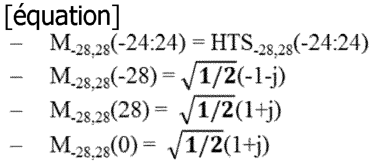 dans lequel HTS-28,28 est défini comme l'équation ci-dessous, et
 le champ HE-STF est construit par configuration de seize valeurs zéro dans le côté gauche de HES-496,496 et quinze valeurs zéro sont configurées dans le côté droit HES-496,496.
Priority Applications (1)
| Application Number | Priority Date | Filing Date | Title |
|---|---|---|---|
| EP23198848.6A EP4274152A3 (fr) | 2014-12-05 | 2015-10-15 | Procédé pour transmettre/recevoir une unité de données de protocole physique (ppdu) dans un système de communication sans fil et appareil associé |
Applications Claiming Priority (6)
| Application Number | Priority Date | Filing Date | Title |
|---|---|---|---|
| US201462087804P | 2014-12-05 | 2014-12-05 | |
| US201462089217P | 2014-12-08 | 2014-12-08 | |
| US201462092843P | 2014-12-17 | 2014-12-17 | |
| US201562120884P | 2015-02-26 | 2015-02-26 | |
| US201562147601P | 2015-04-15 | 2015-04-15 | |
| PCT/KR2015/010888 WO2016089003A1 (fr) | 2014-12-05 | 2015-10-15 | Procédé pour transmettre/recevoir une unité de données de protocole physique (ppdu) dans un système de communication sans fil et appareil associé |
Related Child Applications (2)
| Application Number | Title | Priority Date | Filing Date |
|---|---|---|---|
| EP23198848.6A Division EP4274152A3 (fr) | 2014-12-05 | 2015-10-15 | Procédé pour transmettre/recevoir une unité de données de protocole physique (ppdu) dans un système de communication sans fil et appareil associé |
| EP23198848.6A Division-Into EP4274152A3 (fr) | 2014-12-05 | 2015-10-15 | Procédé pour transmettre/recevoir une unité de données de protocole physique (ppdu) dans un système de communication sans fil et appareil associé |
Publications (3)
| Publication Number | Publication Date |
|---|---|
| EP3229433A1 EP3229433A1 (fr) | 2017-10-11 |
| EP3229433A4 EP3229433A4 (fr) | 2018-07-18 |
| EP3229433B1 true EP3229433B1 (fr) | 2023-11-29 |
Family
ID=56091916
Family Applications (2)
| Application Number | Title | Priority Date | Filing Date |
|---|---|---|---|
| EP23198848.6A Pending EP4274152A3 (fr) | 2014-12-05 | 2015-10-15 | Procédé pour transmettre/recevoir une unité de données de protocole physique (ppdu) dans un système de communication sans fil et appareil associé |
| EP15864589.5A Active EP3229433B1 (fr) | 2014-12-05 | 2015-10-15 | Procédé pour transmettre/recevoir une unité de données de protocole physique (ppdu) dans un système de communication sans fil et appareil associé |
Family Applications Before (1)
| Application Number | Title | Priority Date | Filing Date |
|---|---|---|---|
| EP23198848.6A Pending EP4274152A3 (fr) | 2014-12-05 | 2015-10-15 | Procédé pour transmettre/recevoir une unité de données de protocole physique (ppdu) dans un système de communication sans fil et appareil associé |
Country Status (4)
| Country | Link |
|---|---|
| US (1) | US10911193B2 (fr) |
| EP (2) | EP4274152A3 (fr) |
| KR (1) | KR102550807B1 (fr) |
| WO (1) | WO2016089003A1 (fr) |
Families Citing this family (15)
| Publication number | Priority date | Publication date | Assignee | Title |
|---|---|---|---|---|
| CN106797647B (zh) * | 2014-10-16 | 2020-06-09 | Lg电子株式会社 | 在无线lan中在不同大小的带宽中分配无线资源的方法和装置 |
| WO2017007266A1 (fr) * | 2015-07-07 | 2017-01-12 | 엘지전자 주식회사 | Procédé d'opération de sondage dans un système de réseau local sans fil et appareil correspondant |
| CN106604203B (zh) | 2015-10-20 | 2020-12-25 | 华为技术有限公司 | 无线局域网中站点间直接通信的方法及相关设备 |
| US10356784B2 (en) * | 2016-06-14 | 2019-07-16 | Lg Electronics Inc. | Method and apparatus for constructing control field including information regarding resource unit in wireless local area network system |
| US11283575B2 (en) * | 2016-11-10 | 2022-03-22 | Qualcomm Incorporated | Sequence generation for systems supporting mixed numerologies |
| CN108123742B (zh) * | 2016-11-26 | 2021-10-26 | 华为技术有限公司 | 一种数据处理方法、数据发送装置以及数据接收装置 |
| DE112017007168T5 (de) * | 2017-03-01 | 2019-11-14 | Intel IP Corporation | Delegieren von autonomität auf basis von netzwerkbedingungen in einer mehrfach-zugriffspunkt-umgebung |
| US10687321B2 (en) * | 2017-06-20 | 2020-06-16 | Mediatek Inc. | Network communication link adaptation systems and methods |
| US10667265B2 (en) * | 2018-01-17 | 2020-05-26 | Intel IP Corporation | Enhanced tone mapping for trigger-based null data packet feedback |
| WO2020145546A1 (fr) * | 2019-01-07 | 2020-07-16 | 엘지전자 주식회사 | Procédé et dispositif de transmission d'une ppdu eht dans un système lan sans fil |
| US10904061B2 (en) * | 2019-01-16 | 2021-01-26 | Qualcomm Incorporated | Signal phase rotation |
| KR102595373B1 (ko) * | 2019-08-12 | 2023-10-31 | 엘지전자 주식회사 | 무선랜 시스템에서 광대역을 통해 ppdu를 수신하는 방법 및 장치 |
| CN114424485B (zh) * | 2019-08-12 | 2024-04-12 | Lg电子株式会社 | 在无线通信系统中配置前导的技术 |
| WO2021045518A1 (fr) * | 2019-09-03 | 2021-03-11 | 엘지전자 주식회사 | Technique de configuration de préambule dans un système de communication sans fil |
| US11962371B2 (en) * | 2020-04-08 | 2024-04-16 | Lg Electronics Inc. | Method and device for applying optimized phase rotation to broadband in wireless LAN system |
Family Cites Families (21)
| Publication number | Priority date | Publication date | Assignee | Title |
|---|---|---|---|---|
| US8717865B2 (en) * | 2009-07-17 | 2014-05-06 | Qualcomm Incorporated | Method and apparatus for constructing very high throughput short training field sequences |
| KR20110027533A (ko) | 2009-09-09 | 2011-03-16 | 엘지전자 주식회사 | 다중 안테나 시스템에서 제어정보 전송 방법 및 장치 |
| EP2357773B1 (fr) | 2010-02-10 | 2018-01-10 | Avago Technologies General IP (Singapore) Pte. Ltd | Allocation de bits dans la préambule et la tête pour les économies d'énergie au sein de plusieurs utilisateurs, l'accès multiples, et / ou systèmes de communication sans fil MIMO |
| US20120269142A1 (en) | 2011-04-24 | 2012-10-25 | Broadcom Corporation | Doppler adaptation using pilot patterns within single user, multiple user, multiple access, and/or MIMO wireless communications |
| TWI574533B (zh) | 2011-06-24 | 2017-03-11 | 內數位專利控股公司 | 用於在多用戶多輸入多輸出通訊中接收前導碼的方法及無線傳輸/接收單元 |
| US20130230120A1 (en) * | 2011-08-29 | 2013-09-05 | Qualcomm Incorporated | Apparatus and methods for long and short training sequences for a fast fourier transform |
| KR20150013640A (ko) * | 2012-04-30 | 2015-02-05 | 인터디지탈 패튼 홀딩스, 인크 | 협력형 직교 블록 기반 자원 할당(cobra) 동작을 지원하는 방법 및 장치 |
| US20140211775A1 (en) | 2013-01-28 | 2014-07-31 | Qualcomm Incorporated | Larger delay spread support for wifi bands |
| US10439773B2 (en) | 2013-04-15 | 2019-10-08 | Qualcomm Incorporated | Systems and methods for backwards-compatible preamble formats for multiple access wireless communication |
| KR102526618B1 (ko) * | 2013-10-25 | 2023-04-27 | 마벨 아시아 피티이 엘티디. | 와이파이를 위한 레인지 확장 모드 |
| CN112217624A (zh) * | 2013-11-27 | 2021-01-12 | 马维尔亚洲私人有限公司 | 用于无线局域网的正交频分多址的通信方法和通信设备 |
| EP3162152A4 (fr) * | 2014-06-27 | 2018-03-07 | Techflux Ltd. | Procédé et dispositif de transmission de données |
| CN106664277B (zh) * | 2014-06-27 | 2021-09-07 | 泰科弗勒克斯公司 | 用于发送数据单元的方法和装置 |
| WO2016009278A2 (fr) * | 2014-06-27 | 2016-01-21 | Techflux, Ltd. | Procédé et dispositif de transmission de données |
| EP3161990A4 (fr) * | 2014-06-27 | 2018-03-14 | Techflux Ltd. | Signalisation de bande passante |
| EP3162028B8 (fr) * | 2014-06-27 | 2019-12-04 | Techflux Inc. | Procédé et dispositif de transmission de données |
| WO2015198144A2 (fr) * | 2014-06-27 | 2015-12-30 | Techflux, Ltd. | Procédé et dispositif de transmission d'une unité de données |
| EP3198817B8 (fr) * | 2014-09-23 | 2020-04-01 | NXP USA, Inc. | Champ d'entraînement court pour wifi |
| EP3190737A4 (fr) * | 2014-09-28 | 2017-09-06 | Huawei Technologies Co., Ltd. | Procédé de génération de séquence de domaine d'apprentissage courte à haute efficacité et procédé et appareil de transmission et de réception de signaux |
| US9838232B2 (en) * | 2014-10-29 | 2017-12-05 | Intel IP Corporation | Wireless device, method, and computer readable media for signaling a short training field in a high-efficiency wireless local area network |
| US10050750B2 (en) * | 2014-12-09 | 2018-08-14 | Qualcomm Incorporated | Training field tone plans for mixed-rate wireless communication networks |
-
2015
- 2015-10-15 EP EP23198848.6A patent/EP4274152A3/fr active Pending
- 2015-10-15 US US15/329,227 patent/US10911193B2/en active Active
- 2015-10-15 KR KR1020167024098A patent/KR102550807B1/ko active IP Right Grant
- 2015-10-15 WO PCT/KR2015/010888 patent/WO2016089003A1/fr active Application Filing
- 2015-10-15 EP EP15864589.5A patent/EP3229433B1/fr active Active
Also Published As
| Publication number | Publication date |
|---|---|
| KR20170092447A (ko) | 2017-08-11 |
| EP4274152A2 (fr) | 2023-11-08 |
| WO2016089003A1 (fr) | 2016-06-09 |
| EP4274152A3 (fr) | 2024-02-28 |
| US10911193B2 (en) | 2021-02-02 |
| KR102550807B1 (ko) | 2023-07-03 |
| EP3229433A4 (fr) | 2018-07-18 |
| EP3229433A1 (fr) | 2017-10-11 |
| US20180212725A1 (en) | 2018-07-26 |
Similar Documents
| Publication | Publication Date | Title |
|---|---|---|
| US11671219B2 (en) | Method for multi-user transmission and reception in wireless communication system and device for same | |
| US11228411B2 (en) | Multiuser transreceiving method in wireless communication system and device for same | |
| EP3229433B1 (fr) | Procédé pour transmettre/recevoir une unité de données de protocole physique (ppdu) dans un système de communication sans fil et appareil associé | |
| EP3496354B1 (fr) | Procédé destiné à une transmission en liaison montante dans un système de communication sans fil, et appareil correspondant | |
| EP3588888B1 (fr) | Procédéprocédé de transmission de données dans un système de communication sans fil et dispositif correspondant | |
| EP3907953B1 (fr) | Procédé et appareil de transmission de données dans un système de communication sans fil | |
| US10411931B2 (en) | Method for transreceiving PPDU in wireless communication system and device for same | |
| US10616020B2 (en) | Transmitting and receiving device and method in wireless communication system | |
| US10225124B2 (en) | Transmitting and receiving device and method in wireless communication system | |
| EP3264704B1 (fr) | Dispositif et procédé de transmission et de réception dans un système de communication sans fil |
Legal Events
| Date | Code | Title | Description |
|---|---|---|---|
| STAA | Information on the status of an ep patent application or granted ep patent |
Free format text: STATUS: THE INTERNATIONAL PUBLICATION HAS BEEN MADE |
|
| PUAI | Public reference made under article 153(3) epc to a published international application that has entered the european phase |
Free format text: ORIGINAL CODE: 0009012 |
|
| STAA | Information on the status of an ep patent application or granted ep patent |
Free format text: STATUS: REQUEST FOR EXAMINATION WAS MADE |
|
| 17P | Request for examination filed |
Effective date: 20160919 |
|
| AK | Designated contracting states |
Kind code of ref document: A1 Designated state(s): AL AT BE BG CH CY CZ DE DK EE ES FI FR GB GR HR HU IE IS IT LI LT LU LV MC MK MT NL NO PL PT RO RS SE SI SK SM TR |
|
| AX | Request for extension of the european patent |
Extension state: BA ME |
|
| DAV | Request for validation of the european patent (deleted) | ||
| DAX | Request for extension of the european patent (deleted) | ||
| A4 | Supplementary search report drawn up and despatched |
Effective date: 20180618 |
|
| RIC1 | Information provided on ipc code assigned before grant |
Ipc: H04L 27/26 20060101AFI20180612BHEP |
|
| STAA | Information on the status of an ep patent application or granted ep patent |
Free format text: STATUS: EXAMINATION IS IN PROGRESS |
|
| 17Q | First examination report despatched |
Effective date: 20190328 |
|
| STAA | Information on the status of an ep patent application or granted ep patent |
Free format text: STATUS: EXAMINATION IS IN PROGRESS |
|
| STAA | Information on the status of an ep patent application or granted ep patent |
Free format text: STATUS: EXAMINATION IS IN PROGRESS |
|
| RIC1 | Information provided on ipc code assigned before grant |
Ipc: H04L 5/00 20060101ALI20230315BHEP Ipc: H04L 27/26 20060101AFI20230315BHEP |
|
| GRAP | Despatch of communication of intention to grant a patent |
Free format text: ORIGINAL CODE: EPIDOSNIGR1 |
|
| STAA | Information on the status of an ep patent application or granted ep patent |
Free format text: STATUS: GRANT OF PATENT IS INTENDED |
|
| INTG | Intention to grant announced |
Effective date: 20230428 |
|
| GRAS | Grant fee paid |
Free format text: ORIGINAL CODE: EPIDOSNIGR3 |
|
| GRAA | (expected) grant |
Free format text: ORIGINAL CODE: 0009210 |
|
| STAA | Information on the status of an ep patent application or granted ep patent |
Free format text: STATUS: THE PATENT HAS BEEN GRANTED |
|
| AK | Designated contracting states |
Kind code of ref document: B1 Designated state(s): AL AT BE BG CH CY CZ DE DK EE ES FI FR GB GR HR HU IE IS IT LI LT LU LV MC MK MT NL NO PL PT RO RS SE SI SK SM TR |
|
| REG | Reference to a national code |
Ref country code: GB Ref legal event code: FG4D |
|
| REG | Reference to a national code |
Ref country code: CH Ref legal event code: EP |
|
| REG | Reference to a national code |
Ref country code: DE Ref legal event code: R096 Ref document number: 602015086768 Country of ref document: DE |
|
| REG | Reference to a national code |
Ref country code: IE Ref legal event code: FG4D |
|
| REG | Reference to a national code |
Ref country code: LT Ref legal event code: MG9D |
|
| REG | Reference to a national code |
Ref country code: NL Ref legal event code: MP Effective date: 20231129 |
|
| PG25 | Lapsed in a contracting state [announced via postgrant information from national office to epo] |
Ref country code: GR Free format text: LAPSE BECAUSE OF FAILURE TO SUBMIT A TRANSLATION OF THE DESCRIPTION OR TO PAY THE FEE WITHIN THE PRESCRIBED TIME-LIMIT Effective date: 20240301 |
|
| PG25 | Lapsed in a contracting state [announced via postgrant information from national office to epo] |
Ref country code: IS Free format text: LAPSE BECAUSE OF FAILURE TO SUBMIT A TRANSLATION OF THE DESCRIPTION OR TO PAY THE FEE WITHIN THE PRESCRIBED TIME-LIMIT Effective date: 20240329 |
|
| PG25 | Lapsed in a contracting state [announced via postgrant information from national office to epo] |
Ref country code: LT Free format text: LAPSE BECAUSE OF FAILURE TO SUBMIT A TRANSLATION OF THE DESCRIPTION OR TO PAY THE FEE WITHIN THE PRESCRIBED TIME-LIMIT Effective date: 20231129 |