EP3229409B1 - Elektronische vorrichtung und externes vorrichtungssteuerungsverfahren dafür - Google Patents
Elektronische vorrichtung und externes vorrichtungssteuerungsverfahren dafür Download PDFInfo
- Publication number
- EP3229409B1 EP3229409B1 EP17153981.0A EP17153981A EP3229409B1 EP 3229409 B1 EP3229409 B1 EP 3229409B1 EP 17153981 A EP17153981 A EP 17153981A EP 3229409 B1 EP3229409 B1 EP 3229409B1
- Authority
- EP
- European Patent Office
- Prior art keywords
- external apparatus
- external
- information
- action
- electronic apparatus
- Prior art date
- Legal status (The legal status is an assumption and is not a legal conclusion. Google has not performed a legal analysis and makes no representation as to the accuracy of the status listed.)
- Active
Links
Images




Classifications
-
- H—ELECTRICITY
- H04—ELECTRIC COMMUNICATION TECHNIQUE
- H04L—TRANSMISSION OF DIGITAL INFORMATION, e.g. TELEGRAPHIC COMMUNICATION
- H04L67/00—Network arrangements or protocols for supporting network services or applications
- H04L67/01—Protocols
- H04L67/12—Protocols specially adapted for proprietary or special-purpose networking environments, e.g. medical networks, sensor networks, networks in vehicles or remote metering networks
- H04L67/125—Protocols specially adapted for proprietary or special-purpose networking environments, e.g. medical networks, sensor networks, networks in vehicles or remote metering networks involving control of end-device applications over a network
-
- H—ELECTRICITY
- H04—ELECTRIC COMMUNICATION TECHNIQUE
- H04L—TRANSMISSION OF DIGITAL INFORMATION, e.g. TELEGRAPHIC COMMUNICATION
- H04L67/00—Network arrangements or protocols for supporting network services or applications
- H04L67/01—Protocols
- H04L67/12—Protocols specially adapted for proprietary or special-purpose networking environments, e.g. medical networks, sensor networks, networks in vehicles or remote metering networks
-
- H—ELECTRICITY
- H04—ELECTRIC COMMUNICATION TECHNIQUE
- H04L—TRANSMISSION OF DIGITAL INFORMATION, e.g. TELEGRAPHIC COMMUNICATION
- H04L12/00—Data switching networks
- H04L12/28—Data switching networks characterised by path configuration, e.g. LAN [Local Area Networks] or WAN [Wide Area Networks]
- H04L12/2803—Home automation networks
- H04L12/2816—Controlling appliance services of a home automation network by calling their functionalities
- H04L12/282—Controlling appliance services of a home automation network by calling their functionalities based on user interaction within the home
-
- H—ELECTRICITY
- H04—ELECTRIC COMMUNICATION TECHNIQUE
- H04L—TRANSMISSION OF DIGITAL INFORMATION, e.g. TELEGRAPHIC COMMUNICATION
- H04L12/00—Data switching networks
- H04L12/28—Data switching networks characterised by path configuration, e.g. LAN [Local Area Networks] or WAN [Wide Area Networks]
- H04L12/2803—Home automation networks
- H04L12/2807—Exchanging configuration information on appliance services in a home automation network
- H04L12/2814—Exchanging control software or macros for controlling appliance services in a home automation network
-
- H—ELECTRICITY
- H04—ELECTRIC COMMUNICATION TECHNIQUE
- H04L—TRANSMISSION OF DIGITAL INFORMATION, e.g. TELEGRAPHIC COMMUNICATION
- H04L12/00—Data switching networks
- H04L12/28—Data switching networks characterised by path configuration, e.g. LAN [Local Area Networks] or WAN [Wide Area Networks]
- H04L12/2803—Home automation networks
- H04L12/2816—Controlling appliance services of a home automation network by calling their functionalities
-
- H—ELECTRICITY
- H04—ELECTRIC COMMUNICATION TECHNIQUE
- H04L—TRANSMISSION OF DIGITAL INFORMATION, e.g. TELEGRAPHIC COMMUNICATION
- H04L12/00—Data switching networks
- H04L12/28—Data switching networks characterised by path configuration, e.g. LAN [Local Area Networks] or WAN [Wide Area Networks]
- H04L12/2803—Home automation networks
- H04L12/2823—Reporting information sensed by appliance or service execution status of appliance services in a home automation network
- H04L12/2827—Reporting to a device within the home network; wherein the reception of the information reported automatically triggers the execution of a home appliance functionality
- H04L12/2829—Reporting to a device within the home network; wherein the reception of the information reported automatically triggers the execution of a home appliance functionality involving user profiles according to which the execution of a home appliance functionality is automatically triggered
-
- H—ELECTRICITY
- H04—ELECTRIC COMMUNICATION TECHNIQUE
- H04L—TRANSMISSION OF DIGITAL INFORMATION, e.g. TELEGRAPHIC COMMUNICATION
- H04L67/00—Network arrangements or protocols for supporting network services or applications
- H04L67/50—Network services
- H04L67/51—Discovery or management thereof, e.g. service location protocol [SLP] or web services
-
- H—ELECTRICITY
- H04—ELECTRIC COMMUNICATION TECHNIQUE
- H04L—TRANSMISSION OF DIGITAL INFORMATION, e.g. TELEGRAPHIC COMMUNICATION
- H04L12/00—Data switching networks
- H04L12/28—Data switching networks characterised by path configuration, e.g. LAN [Local Area Networks] or WAN [Wide Area Networks]
- H04L12/2803—Home automation networks
- H04L2012/284—Home automation networks characterised by the type of medium used
- H04L2012/2841—Wireless
-
- H—ELECTRICITY
- H04—ELECTRIC COMMUNICATION TECHNIQUE
- H04L—TRANSMISSION OF DIGITAL INFORMATION, e.g. TELEGRAPHIC COMMUNICATION
- H04L12/00—Data switching networks
- H04L12/28—Data switching networks characterised by path configuration, e.g. LAN [Local Area Networks] or WAN [Wide Area Networks]
- H04L12/2803—Home automation networks
- H04L2012/2847—Home automation networks characterised by the type of home appliance used
- H04L2012/285—Generic home appliances, e.g. refrigerators
-
- H—ELECTRICITY
- H04—ELECTRIC COMMUNICATION TECHNIQUE
- H04L—TRANSMISSION OF DIGITAL INFORMATION, e.g. TELEGRAPHIC COMMUNICATION
- H04L63/00—Network architectures or network communication protocols for network security
- H04L63/10—Network architectures or network communication protocols for network security for controlling access to devices or network resources
Definitions
- the present invention relates generally to an electronic apparatus and an external apparatus controlling method thereof, and for example, to an electronic apparatus that controls an external apparatus using external apparatus information and content information of a user and an external apparatus controlling method thereof.
- IoT Internet of Things
- An external apparatus operated in an environment of the IoT is called an IoT apparatus.
- an IoT apparatus In order to efficiently control such an external apparatus, a user should know functions and features of each external apparatus well. Studies to identify and efficiently control various external apparatuses in the IoT environment are being carried out. Specifically, a service, operating an external apparatus by analyzing history about how a user used an external apparatus, is provided.
- An electronic apparatus analyzes an operation condition and a feature using knowledge information stored in a memory about external apparatuses placed in a home and determines an external apparatus to operate by considering relations of the external apparatuses. Therefore, the electronic apparatus may control the most appropriate external apparatus to be operated in the current condition even though records of the external apparatuses use are not accumulated.
- An example aspect of the present invention is to determine and operate an external apparatus based on a current condition and in consideration of context information of the user.
- the invention is defined by the appended independent claims. Preferred embodiments are defined by the dependent claims. Further “embodiments” described in this description which do not fall within the scope of the appended claims shall serve as examples for a better understanding of the invention.
- the electronic apparatus has many advantages. Among the advantages is that an external apparatus most appropriate in a condition of a current user is selected and operated even though records of the external apparatus use are not accumulated. This is made possible because the electronic apparatus collects information on various external apparatuses using knowledge information stored in a memory and an action template, analyzes an operating condition and functions of external apparatuses, determines an external apparatus to perform a function considering relations of respective external apparatuses and operates the external apparatus.
- a "module” or a “unit” performs at least one function or operation, and may be implemented in hardware, software, or a combination of hardware and software.
- a plurality of ⁇ modules' or a plurality of ⁇ units' may be integrated into at least one module and may be implemented in at least one processor (not illustrated), except for a ⁇ module' or a 'unit' in which they need to be implemented in specific hardware.
- an electronic apparatus may be, for example, a smartphone, a TV, a home appliance or an audio device, or the like, but is not limited thereto.
- an electronic apparatus according to an example embodiment is not limited to the described apparatuses and may be a new electronic apparatus according to technology development.
- a term "user” may indicate a user who uses an electronic apparatus or an apparatus that uses an electronic apparatus (for example, an artificial intelligence (AI) electronic apparatus).
- AI artificial intelligence
- FIG. 1 is a diagram illustrating an example system configuration of an electronic apparatus and external apparatuses according to an example embodiment.
- FIG. 1 illustrates an electronic apparatus 201 and external apparatuses 311, 313, 315, 317, 319, 321, 325.
- the external apparatuses 311, 313, 315, 317, 319, 321, 325 may be IoT apparatuses.
- the electronic apparatus 201 may be, for example, a smart TV or a smartphone but it is not limited thereto.
- the electronic apparatus 201 may include a communication function and may transmit or receive data by communicating with the surrounding external apparatuses 311, 313, 315, 317, 319, 321, 325.
- the electronic apparatus 201 will be described in greater detail below with reference to FIGS. 3 and 4 .
- the external apparatuses 311, 313, 315, 317, 319, 321, 325 may have a communication function and may transceiver data with the electronic apparatus 201, by communicating with the electronic apparatus 201.
- the external apparatuses 311, 313, 315, 317, 319, 321, 325 may be classified into an IoT sensor 319 including a communication function that is sensing a surrounding environment and an IoT home appliance 311, 313, 315, 317, 321, 325 including a communication function.
- an external apparatus may be a microwave oven 311 including a communication function.
- the electronic apparatus 201 may receive operation hours of the microwave oven 311 and data regarding an indoor temperature and a cooking state from the microwave oven 311 and control an operation of the microwave oven 311.
- the electronic apparatus may be a lighting apparatus 313 including a communication function.
- the electronic apparatus 201 may receive data regarding a current state and a current light level of the light apparatus 313 from the light apparatus 313 and control an operation of the light apparatus 313.
- the electronic apparatus may be a refrigerator 315 including a communication function.
- the electronic apparatus 201 may receive data regarding a state and a temperature of the refrigerator from the refrigerator 315 and control an operation of the refrigerator 315.
- the electronic apparatus 201 may communicate with the external apparatuses 311, 313, 315, 317, 319, 321 through the short range communication.
- the electronic apparatus 201 may receive log information from the external apparatuses 311, 313, 315, 317, 319, 321 through the short range communication.
- the log information may include identification information and state information of the external apparatus. The log information will be described in greater detail below with reference to FIG. 2 .
- An example of the short range communication may be Zigbee, WiFi or Bluetooth (BT) communication.
- the electronic apparatus 201 may communicate with a server 325 through the long range communication.
- the electronic apparatus 201 may receive information regarding an external apparatus from the server 325.
- the electronic apparatus 201 may receive knowledge information and information regarding an action template of an external apparatus from the server 325 in real time or receive update information regarding the knowledge information and the action template.
- the knowledge information may include, for example, and without limitation, a table in which a function of an external apparatus and parameters that each function of the external apparatus can have are defined in detail and may be stored in a form of database in a memory.
- the knowledge information will be described in greater detail below with reference to FIG. 6 .
- the action template may include, for example, and without limitation, a set of commands defined in a user's position and a table in which a condition to perform a command and at least one external apparatus to perform the command are defined and the action template may be stored in a form of database in a memory.
- the action template will be described in greater detail below with reference to FIG. 7 .
- the telecommunication may be 3G or LTE.
- the electronic apparatus 201 may communicate with the server 325 on the Internet.
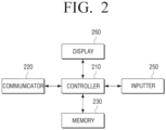
- FIG. 2 is a block diagram illustrating an example electronic apparatus according to an example embodiment.
- FIG. 2 illustrates a controller (e.g., including processing circuitry) 210, a communicator (e.g., including communication circuitry) 220, a memory 230, an inputter (e.g., including input circuitry) 250 and a display 260.
- a controller e.g., including processing circuitry
- a communicator e.g., including communication circuitry
- a memory 230 e.g., including communication circuitry
- an inputter e.g., including input circuitry
- the communicator 220 may include various communication circuitry configured to communicate with an external apparatus and a server.
- the communicator 220 may communicate with an external apparatus and receive log information transmitted from the external apparatus.
- the log information may include identification information (ID) of the external apparatus.
- the communicator 220 may include a short range communication communicator and a long range communication communicator.
- the electronic apparatus may communicate with an external apparatus through the short range communication communicator.
- the electronic apparatus 201 may communicate with the server through the long range communication communicator. Specific elements of the communicator 220 will be described in greater detail below with reference to FIG. 3 .
- the memory 230 may store log information received from the external apparatus.
- the log information may include state information of the external apparatus, external environment information that the external apparatus collected, identification information (ID: Identification Data) of the external apparatus and information regarding time in which the external apparatus collected data.
- ID Identification Data
- the external environment information may be about a current temperature and humidity around the external apparatus.
- the log information may be a current temperature of the refrigerator and a current time.
- the external apparatus is an air conditioner
- the log information may be an operation state and a temperature around the air conditioner.
- the external apparatus is a motion sensor
- the log information may be about a time and a location where a motion is sensed.
- the external apparatus is an illumination sensor
- the log information may be about a surrounding illumination level.
- the memory 230 may store knowledge information and an action template.
- the knowledge information and the action template may be received from the server and be updated periodically.
- the knowledge information may include detailed information on an external apparatus.
- the knowledge information may include, for example, and without limitation, a table in which a function of the external apparatus and a type of data and a data value that each function can have are defined in detail.
- the knowledge information may be stored in a form of database in a memory. The knowledge information will be described in detail with reference to FIG. 6 .
- the action template may include, for example, and without limitation, a table in which an operation of the external apparatus is defined.
- the action template is also a set of commands defined in a user's position.
- a condition to perform a command and at least one external apparatus to perform the command are defined and the action template may be stored in a form of database in a memory. The action template will be described in greater detail below with reference to FIG. 7 .
- a sensing unit may sense information regarding an environment around a user. In addition, the sensing unit may sense a movement of the user. The sensing unit may output an electronic signal corresponding to a sensed value to the controller 210. The sensing unit may be included in the electronic apparatus or may be in a separate external apparatus form. A specific operation and examples of the sensing unit will be described in detail with reference to FIG. 3 .
- the inputter 250 may include various circuitry configured to receive an input, e.g., a user input.
- the inputter 250 may include various input circuitry, such as, for example, and without limitation, a keyboard, a touch or a motion input and a user may interact with the electronic apparatus through the inputter.
- the inputter 250 will be described in greater detail below with reference to FIG. 3 .
- the display 260 may display a message to a user.
- the display 260 may display a message requesting for a check to the user and/or display a graphic object that can receive a user input. Examples of the display 260 will be described in greater detail below with reference to FIG. 3 .
- the controller 210 may include various processing circuitry and controls overall operation of the electronic apparatus.
- the controller 210 may receive log information transmitted from an external apparatus through a communicator and acquire knowledge information corresponding to the external apparatus based on the log information from a memory. Then, the controller 210 may determine an external apparatus to operate from an action template based on the knowledge information and operate the external apparatus according to an action included in the action template.
- the controller 210 may determine an external apparatus to operate from the action template based on at least one of environment information around the electronic apparatus 201 and movement information of a user and control the external apparatus to perform an operation defined in the action template.
- the environment information may be acquired based on log information.
- the log information is acquired from the external apparatus and the external apparatus may collect environment information around the electronic apparatus.
- the external apparatus may sense humidity or a temperature around the electronic apparatus and transmit the information about sensing to the electronic apparatus and the electronic apparatus may check humidity or a temperature around the electronic apparatus by analyzing data received from the external apparatus.
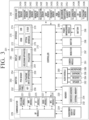
- FIG. 3 is a block diagram illustrating an example electronic apparatus according to an example embodiment.
- the electronic apparatus 201 may include the controller (e.g., including processing circuitry) 210, the communicator (e.g., including communication circuitry) 220, a subscriber identity module 224, the memory 230, a sensing unit 240, the inputter (e.g., including input circuitry) 250, the display 260, an interface (e.g., including interface circuitry) 270, an audio module 280, a camera module 291, a power management module 295, a battery 296, an indicator 297 and a motor 298.
- the controller e.g., including processing circuitry
- the communicator e.g., including communication circuitry
- the memory 230 e.g., a subscriber identity module 224
- the inputter e.g., including input circuitry
- the display 260 e.g., an interface circuitry
- an audio module 280 e.g., including audio module
- a camera module 291 e.g., including camera module
- the controller 210 may include various processing circuitry configured to control a plurality of hardware elements or software elements that are connected to the controller 210 by driving an operating system or an application program and may process various data and perform calculations.
- the controller 210 may be realized as a system on chip (SoC).
- the controller 210 may further include a graphic processing unit (GPU) and/or an image signal processor.
- the controller 210 may include at least one (for example, a cellular module 221) of the elements illustrated in FIG. 3 .
- the controller 210 may load a command or the data received from at least one of other elements (for example, a non-volatile memory) in a volatile memory and process the command or the data and store various data in the non-volatile memory.
- the communicator 220 may have a configuration which is the same as or similar to the communicator 170 in FIG. 2 .
- the communicator 220 may include various communication circuitry, such as, for example, and without limitation, the cellular module 221, a WiFi module 223, a BT module 225, a GNSS module 227 (for example, a GPS module, a Glonass module, a Beidou module or a Galileo module), an NFC module 228 and a radio frequency (RF) module 229.
- the cellular module 221, a WiFi module 223, a BT module 225, a GNSS module 227 for example, a GPS module, a Glonass module, a Beidou module or a Galileo module
- an NFC module 228 and a radio frequency (RF) module 229.
- RF radio frequency
- the cellular module 221 may provide a voice call, a video call, a text message service, or an Internet service via a communication network.
- the cellular module 221 may identify or authenticate the electronic apparatus 201 in the communication network by using a subscriber identity module 224 (for example, a SIM card).
- the cellular module 221 may perform at least a function among functions that can be provided by the controller 210.
- the cellular module 221 may include a communication processor (CP).
- Each of the WiFi module 223, the BT module 225, the GNSS module 227 and the NFC module 228, for example, may include a processor to process data that is transmitted/received through a corresponding module.
- some of the cellular module 221, the WiFi module 223, the BT module 225, the GNSS module 227 and the NFC module 228 may be included in an integrated chip (IC) or in an IC package.
- the RF module 229 may transcieve a communication signal (for example, an RF signal).
- the RF module 229 may include a transceiver, a power amp module (PAM), a frequency filter, a low noise amplifier (LNA), an antenna or the like.
- PAM power amp module
- LNA low noise amplifier
- at least one of the cellular module 221, the WiFi module 223, the BT module 225, the GNSS module 227 and the NFC module 228 may transcieve an RF signal through a separate RF module.
- the memory 230 may include an embedded memory 232 and/or an external memory 234.
- the embedded memory 232 may include at least one of a volatile memory (for example, a dynamic RAM (DRAM) memory, a static RAM (SRAM) and a synchronous dynamic RAM (SDRAM)) and a non-volatile memory (for example, a one-time programmable ROM (OTPROM), a programmable ROM (PROM), an erasable and programmable ROM (EPROM), an electrically erasable and programmable ROM (EEPROM), a mask ROM, a flash ROM, a flash memory (for example, a NAND flash, a NOR flash, etc.), a hard drive, a solid state drive (SSD)).
- a volatile memory for example, a dynamic RAM (DRAM) memory, a static RAM (SRAM) and a synchronous dynamic RAM (SDRAM)
- OTPROM one-time programmable ROM
- PROM programmable ROM
- the external memory 234 may further include a compact flash (CF), a secure digital (SD), a micro secure digital (Micro-SD), a mini secure digital (Mini-SD), an extreme digital (xD), a multi-media card (MMC), a memory stick or the like.
- the external memory 234 may be functionally and/or physically connected to the electronic apparatus 201 through various interfaces.
- the sensing unit 240 may measure physical quantity or detect an operation state of the electronic apparatus 201 and convert the measured or detected information into an electronic signal.
- the sensing unit 240 may include at least one of the sensors illustrated in FIG. 3 but it is not limited thereto.
- the sensing unit 240 may further include a control circuit to control at least one sensor therein.
- the example illustrated sensing unit 240 comprises, for example, a gesture sensor 240A, a gyroscope sensor 240B, a pressure sensor 240C, a magnetic sensor 240D, a acceleration sensor 240E, a grip sensor 240F, a proximity sensor 240G, a RGB sensor 240H, a BIO sensor 240I, a temperature/humidity sensor 240J, an illumination sensor 240K, a UV sensor 240M, a ultrasonic sensor 240N.
- the electronic apparatus 201 may further include a processor configured to control the sensing unit 240 in addition to or separately from the controller 210 so as to control the sensing unit 240 while the controller 210 is in a sleep state.
- the inputter 250 may include various input circuitry, such as, for example, and without limitation, a touch panel 252, a (digital) pen sensor 254, a key 256 or an ultrasonic input apparatus 258.
- various input circuitry such as, for example, and without limitation, a touch panel 252, a (digital) pen sensor 254, a key 256 or an ultrasonic input apparatus 258.
- the display 260 may further include a panel 262, a hologram apparatus 264, a projector 266 and a control circuit to control include a panel 262, a hologram apparatus 264, or a projector 266 .
- the interface 270 may include various interface circuitry, such as, for example, and without limitation, a high-definition multimedia interface (HDMI) 272, a universal serial bus (USB) 274, an optical interface 276, or a D-subminiature (D-sub) 278. Additionally or alternatively, the interface 270, for example, may include a mobile high-definition link (MHL) interface, a secure digital (SD) card/multi-media card (MMC) interface, or an Infrared data association (IrDA) standard interface.
- HDMI high-definition multimedia interface
- USB universal serial bus
- optical interface 276, or a D-subminiature (D-sub) 278 may include a mobile high-definition link (MHL) interface, a secure digital (SD) card/multi-media card (MMC) interface, or an Infrared data association (IrDA) standard interface.
- IrDA Infrared data association
- the audio module 280 may convert sound and an electrical signal in bilateral directions.
- the audio module 280 may process sound information inputted or outputted through a speaker 282, a receiver 284, an earphone 286, a microphone 288 or the like.
- the camera module 291 is an apparatus that can shoot a still image and a video and according to an example embodiment, the camera module 291 may include at least one image sensor (for example, a front sensor or a rear sensor), a lens, an image signal controller (ISP) or a flash (for example, an LED or a xenon lamp).
- ISP image signal controller
- flash for example, an LED or a xenon lamp
- the power management module 295 may manage the power of the electronic apparatus 201.
- the power management module 295 may include a power management integrated circuit (PMIC), a charge integrated circuit (charger IC), or a battery or fuel gauge.
- PMIC power management integrated circuit
- charger IC charge integrated circuit
- the PMIC may have a wired and/or wireless recharging method.
- the wireless recharging method may include a magnetic resonance method, a magnetic induction method, an electromagnetic wave method or the like.
- the indicator 297 may display a certain state of the electronic apparatus 201 or a part (for example, the controller 210) of the electronic apparatus 201, for example, a booting state, a message state or a recharging state.
- the motor 298 may convert an electronic signal to a mechanical vibration and generate a vibration effect or a haptic effect.
- the electronic apparatus 201 may include a processing unit (for example, a GPU) for supporting a mobile TV.
- the controller for supporting a mobile TV for example, may process media data according to standards such as digital multimedia broadcasting (DMB) standards, digital video broadcasting (DVB) standards, mediaFlo TM standards, etc.
- DMB digital multimedia broadcasting
- DVD digital video broadcasting
- mediaFlo TM mediaFlo TM
- Each element described in the disclosure may include one or more than one component, and the name of the components may vary depending on a type of the electronic apparatus.
- the electronic apparatus may include at least one of elements that are described in the disclosure, and some of the elements may be omitted or other elements may be added.
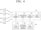
- FIG. 4 is a diagram illustrating an example software block diagram of an example electronic apparatus according to an example embodiment.
- FIG. 4 illustrates external apparatuses 431, 433, 435, 437, the controller 210 and the memory 230.
- Software (e.g., program) modules 411, 413, 415, 417 may be generated in the controller 210.
- IoT log database 419, knowledge database 421 and an action template 422 may be stored in the memory.
- the IoT log database 419 may include log information.
- the knowledge database 421 may include knowledge information regarding a product.
- the software modules 411, 413, 415, 417 may comprise an application, be stored in a form of instruction code in the memory 230 and, when the application is executed, a corresponding function may be performed by the data in the memory 230 being loaded in the controller 210.
- the external apparatus may be an IoT electronic apparatus 431, 433 including a communication function or an IoT sensor 435, 437 that is a normal object having a sensing function and a communication function.
- the external apparatus may transmit ID information (identification information) of a device and log data including a sensing value and state information.
- the application When a program is executed, the application may be loaded from the memory and perform a function.
- the application may include four software modules and database.
- the software modules may include a log manager 411, a knowledge retriever 413, an action generator 415 and an action applier 417.
- the log manager 411 may receive data received from the external apparatuses 431, 433, 435, 437 in real time and store the data in the IoT log database 419.
- the data may be used in identifying an external apparatus placed in a home.
- the data received from the external apparatus may include identification information regarding the external apparatus.
- the electronic apparatus may determine what external apparatus is in a home by analyzing the data. If a user executes an application, the electronic apparatus may acquire information regarding an external apparatus placed in the home through the log manager 411, from the external apparatus.
- the knowledge retriever 413 may retrieve knowledge information corresponding to a certain external apparatus from the knowledge information database 421 based on the data received through the log manager 411, which is the identification information. In other words, the knowledge retriever 413 may retrieve knowledge information corresponding to the identification information of a certain external apparatus that is received through the log manager 411.
- the knowledge information database 421 may include detailed information regarding the external apparatus.
- the knowledge information database 421 may be stored in the memory 230.
- the knowledge information database 421 may be generated when the electronic apparatus is manufactured and updated when the electronic apparatus is connected with a server via a network. In other words, even though the electronic apparatus is not connected with the server, the electronic apparatus may acquire knowledge information corresponding to the external apparatus by using the knowledge information database 421 stored in the memory 230.
- the knowledge information database 421 will be described in greater detail below with reference to FIG. 6 .
- the action generator 415 may select at least one action template corresponding to knowledge information in a plurality of action templates 422 based on the knowledge information received from the knowledge retriever 413 and retrieve an action defined in an action template.
- the action template will be described in greater detail below with reference to FIG. 7 .
- the term "action” may refer, for example, to an operation or a function that the external apparatus performs.
- the electronic apparatus may determine an external apparatus to perform the action and transmit a command regarding the action to the external apparatus through the action applier 417.
- the electronic apparatus may request for a user check for information regarding the generated action by outputting the information on a display.
- the electronic apparatus may display a message asking whether to perform an action or not on the display and receive a user input and transmit a command related to the action to a corresponding IoT device.
- FIG. 5 is a flowchart illustrating an example method of operating an electronic apparatus according to an example embodiment.
- the electronic apparatus may acquire information regarding an external apparatus through a communicator.
- the information regarding the external apparatus may include identification information regarding the external apparatus and state information of the external apparatus.
- the electronic apparatus may acquire user context information based on the information regarding the external apparatus.
- the user context information may include a user behavior pattern and records on external apparatus use of the user.
- the sensing unit may be included in the electronic apparatus or placed outside of the electronic apparatus as an external apparatus.
- a motion detecting sensor may be placed in a main place in a home and detect whether a user is present or not. If a plurality of motion detecting sensors are placed in the home, the electronic apparatus may receive a signal outputted from each motion detecting sensor, analyze the signal and trace a moving path of the user in the home.
- the electronic apparatus may acquire context information of the user by analyzing information of the external apparatus and identifying a pattern in which the user operates the external apparatus.
- the electronic apparatus may acquire knowledge information regarding the external apparatus included in the memory based on the external apparatus information.
- the knowledge information may include detailed information regarding the external apparatus.
- Knowledge information regarding the plurality of external apparatuses may be included in the knowledge information database and the electronic apparatus may acquire knowledge information regarding the external apparatus that is placed in the home or the user possesses by using the identification information (ID) of the external apparatus.
- the knowledge information regarding the external apparatus may be stored in a memory when the product is manufactured or received from a server and may be updated periodically.
- the knowledge information regarding the external apparatus may be provided by a manufacturer that manufactures the external apparatus or a user may directly generate the knowledge information.
- the electronic apparatus may display a user interface (UI) by which the knowledge information regarding the external apparatus may be edited or generated.
- UI user interface
- the electronic apparatus may acquire an action that can cause the external apparatus to be operated using a rule defined in an action template based on the knowledge information. For example, the electronic apparatus may determine an external apparatus to perform the action in a rule field of the action template by using the knowledge information.
- the action template may include information that defines an operation of the external apparatus. Specifically, the action template may include a name of an external apparatus to be operated, a condition for operating the external apparatus and a command to perform an operation in response to the condition being satisfied.
- a controller of the electronic apparatus may select at least one action template among the plurality of action templates based on at least one of environment information and user movement information, and control the communicator to transmit a command to perform an operation defined in the selected action template to the external apparatus.
- the electronic apparatus may output the generated action on a display, receive an input from a user and determine the generated action. In response to the action being generated, the electronic apparatus may output information regarding the action to be performed on the display or output as an audio for requesting an input of the user and in response to an input being received from the user, the electronic apparatus may transmit a command corresponding to the external apparatus to perform the action.
- the electronic apparatus may display a desired temperature as 22 °C and desired humidity as 5 % on the display and display a message requesting for a check to a user or display a corresponding graphic object.
- the electronic apparatus may transmit a command to maintain a temperature as 22 °C to an air conditioner and a command to maintain humidity as 5 % to a dehumidifier.
- the electronic apparatus may determine an external apparatus to perform an action by referring to the selected action template and transmit a command to control the external apparatus.
- the external apparatus to perform the action may be included in a rule field of the action template and the electronic apparatus may determine the external apparatus to perform the action by referring to the rule field.
- the electronic apparatus may select an external apparatus which is the most efficient among a plurality of external apparatuses that have similar functions and operate the external apparatus. For example, if a user inputs a command to operate a dehumidifying function, the electronic apparatus may determine the air conditioner and the dehumidifier as external apparatuses which have the dehumidifying function. In response to receiving a command to dehumidify from a user, the electronic apparatus may select a dehumidifier of which power consumption is low and that is dehumidification-efficient, and then the electronic apparatus may operate the dehumidifier.
- the electronic apparatus may output a message suggesting the user to find a factor of increasing humidity near the air conditioner.
- the electronic apparatus may determine that the user feels hot by context information of the user, and perform a dehumidifying operation and lower a temperature at the same time, by operating the air conditioner in response to the command to dehumidify from the user.
- the electronic apparatus may stop a re-operation of the external apparatus. For example, while the dehumidifier is operated according to an action defined in an action template, if the user repetitively stops the dehumidifier operation, the electronic apparatus may determine that the user has stopped the dehumidifier intentionally and the electronic apparatus may stop a re-operation of the dehumidifier. In addition, the electronic apparatus may amend the action template to stop the dehumidifier's operation.
- FIG. 6 is a diagram illustrating an example of knowledge information according to an example embodiment.
- the knowledge information may include information regarding a plurality of external apparatuses.
- the knowledge information may include a function of an external apparatus and a data type and a data value that each function can have.
- the knowledge information may include an ID field 601, a knowledge field 602 and a device type field 603.
- the ID field 601 may include information regarding a name of a product for user identification, a model name and a manufacturer name. For example, if an external apparatus is an air conditioner, the ID field 611 may be generated by combining the manufacturer name "Samsung,” the product name “Aircondition” and model name "q9000.”
- the knowledge field 602 may include a function of a product, a data type and a data value that each function can have.
- an air conditioner may include a power 612, a mode 614, a temperature 616 and a condition 618.
- Each of the elements 612, 614, 616, 618 may have a corresponding data value.
- the power 612 may have ["on", “off'] 613 as a data value.
- the mode 614 may have ["auto", “cool”, “heat”, “dry”, “wind”] 615 as a data value.
- the temperature 616 may have "40" as the highest value and "10" as the lowest value 617.
- the condition 618 may have ["normal", "error”] 619 as a data value.
- the device field 603 may be "airconditioner" 620.
- the ID field 631 is "ge_link_a19" and the ID field 631 can be generated by combining the manufacturer name "ge,” the product name “link” and the model name “aig.”
- the smart light bulb may include “power” 632 and "lux” 634 as elements regarding a function field.
- the "power” 632 may have ["on", “off'] 633 as a data value.
- the "lux” 634 may have "high value”:255, "low value”:0635 as a data value.
- the device type field 603 may be "light” 636.
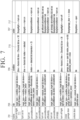
- FIG. 7 is a diagram illustrating an example of an action template according to an example embodiment.
- FIG. 7 illustrates that the action template includes a name field 701, a rule field 703, a condition field 705 and an action field 707.
- the name field 701 may play a role as a call sign regarding an action.
- the action name of an action may be a call signal for selection of a wanted action among a plurality of actions defined in the action template.
- the rule field 703 defines a rule for selection of at least one action among the plurality of actions.
- the rule field 703 may include a name of at least one external apparatus that becomes an object to perform the action and/or information regarding a condition of the selection. If a condition for selecting the action is included in the rule field 703, the electronic apparatus may refer to the condition field 705. In other words, the rule field 703 may refer to the condition field 705.
- the condition field 705 may include a condition to operate the external apparatus.
- the action field 707 may include an external apparatus to perform an action and the action to be performed by the external apparatus.
- the electronic apparatus in response to the condition of the condition field 705 being satisfied, may select at least one external apparatus to perform an action by referring to the action field 707 and control the external apparatus to perform the action.
- the name field 701 may be filled with "turn on light” 711
- the condition field 705 may be filled with "(time > 6oclock && time ⁇ 230clock) && lux ⁇ 50” 715
- FIG. 8 is a flowchart illustrating an example method of generating a routine in an electronic apparatus according to an example embodiment.
- the electronic apparatus receives identification information of an external apparatus from the external apparatus in operation 801. Detailed explanations on the identification information are the same as the above descriptions and thus, detailed explanations are omitted.
- the electronic apparatus may group a plurality of external apparatuses as one based on the received identification information and collectively control the grouped plurality of external apparatuses. In addition, if there are a plurality of external apparatuses operated in a certain period of time based on the identification information received from the external apparatus, the electronic apparatus may make the plurality of external apparatuses as a group.
- the electronic apparatus may determine whether there are patterns of regular use when a user uses the external apparatus and, in response to there being patterns of regular use, the electronic apparatus may generate a routine by grouping the patterns.
- the routine may include information regarding an external apparatus's set value that user sets and information regarding an order of operating external apparatuses. For example, if the user turns on a light in a bedroom at 6 o'clock in the morning, turns on a TV in five minutes and sets and operates an air conditioner to 26 Celsius degrees, the electronic apparatus may receive identification information from the light, the TV and the air conditioner which are external apparatuses.
- information may be received in the order of "the light ⁇ the TV ⁇ the air conditioner" and the electronic apparatus may determine that there are certain patterns in the received identification information and make a group.
- the electronic apparatus analyzes the identification information received for a certain period of time and if an order of received information is identical and the information is repetitively and regularly received, the electronic apparatus may group patterns and generate a routine.
- the routine may include a state of a light (on/off), intensity of illumination, channel information of a TV and a desired temperature of an air conditioner.
- a graphic object corresponding to the generated routine may be displayed on a screen. If the user selects the graphic object displayed on the screen, functions corresponding to the routine may be collectively performed. For example, if routines are generated, the electronic apparatus may display a list of the generated routines on the screen and if the user touches one of the routines, functions regarding the selected routine may be collectively performed.
- the electronic apparatus determines whether generating a routine related to the grouped identification information is required. If it is determined that generating a routine is required, the electronic apparatus may generate a routine in operation 803. In operation 805, the electronic apparatus may analyze identification information received for a certain period of time to generate a routine and determine an order of operating external apparatuses. If the order to operate external apparatuses is regularly repeated, the electronic apparatus may group the external apparatuses as one and generate a routine.
- the electronic apparatus may automatically apply a set value regarding an external apparatus that a user frequently uses into a routine. For example, if external apparatuses included in a routine are a TV and an air conditioner, if a user frequently watches channel 7 on the TV and the user frequently sets a desired temperature of the air conditioner to 26 Celsius degrees, the electronic apparatus may automatically set a set value of the TV included in the routine as channel 7 and a desired temperature of the air conditioner included in the routine to 26 Celsius degrees.
- the electronic apparatus determines whether the routine should be updated in operation 807. If a routine is already generated, the electronic apparatus may determine that generating a routine is not required.
- the electronic apparatus may update a routine based on a routine of use records of a user and identification information. If an external apparatus included in a routine according to a use pattern of the user or a set value regarding the external apparatus is changed, the electronic apparatus may update the routine.
- the electronic apparatus may display a message requesting for a check to the user at some point in operations 803 to 805 on a display and generate a routine by receiving a user input.
- the electronic apparatus may display a message requesting for a check to the user on the display and generate a routine by receiving an input from the user.
- method of controlling an external apparatus of an electronic apparatus as described above may be implemented by at least one execution program (or application) for executing the method of controlling an external apparatus of an electronic apparatus as described above and the execution program may be provided while being stored in a computer readable medium.
- the non-transitory computer readable medium is not a medium that stores data therein for a while, such as a register, a cache, and a memory, but means a medium that semi-permanently stores data therein and is readable by a device.
- various applications or programs described above may be stored and provided in the computer readable medium such as a compact disk (CD), a digital versatile disk (DVD), a hard disk, a Blu-ray disk, a universal serial bus (USB), a memory card, and a read only memory (ROM).
Landscapes
- Engineering & Computer Science (AREA)
- Computer Networks & Wireless Communication (AREA)
- Signal Processing (AREA)
- Automation & Control Theory (AREA)
- Health & Medical Sciences (AREA)
- Computing Systems (AREA)
- General Health & Medical Sciences (AREA)
- Medical Informatics (AREA)
- Human Computer Interaction (AREA)
- Telephone Function (AREA)
- Selective Calling Equipment (AREA)
- User Interface Of Digital Computer (AREA)
Claims (15)
- Elektronisches Gerät, umfassend:einen Kommunikator (220);einen Speicher (230), der konfiguriert ist zum Speichern von Wissensinformationen (601, 602, 603) bezüglich mindestens einer Funktion jedes von mindestens einem externen Gerät und einer Vielzahl von Aktionsvorlagen, die eine Operation des mindestens einen externen Geräts zur Durchführung der mindestens einen Funktion definieren, undeine Steuerung (210), die konfiguriert ist zum:Steuern des Kommunikators, um Identifikationsinformationen des mindestens einen externen Geräts zu empfangen,Erfassen von Wissensinformationen, die dem mindestens einen externen Gerät entsprechen, basierend auf den Identifikationsinformationen des jeweiligen mindestens einen externen Geräts aus dem Speicher, wobei die Wissensinformationen mindestens eine Funktion des jeweiligen mindestens einen externen Geräts und einen Datentyp und einen Datenwert, die jeder der mindestens einen Funktion entsprechen, beinhalten,basierend auf dem Empfangen eines Benutzerbefehls, Identifizieren einer Vielzahl von externen Geräten mit mindestens einer Funktion im Zusammenhang mit dem Benutzerbefehl basierend auf den Wissensinformationen, die jedem der Vielzahl von externen Geräten entsprechen,Vergleichen der Effizienz der mindestens einen Funktion im Zusammenhang mit dem Benutzerbefehl für jedes der Vielzahl von externen Geräten basierend auf den Wissensinformationen, die jedem der Vielzahl von externen Geräten entsprechen, und Identifizieren des effizientesten externen Geräts basierend auf dem Ergebnis des Vergleichs;Erfassen einer Aktionsvorlage, die einer Operation des identifizierten externen Geräts entspricht, zum Durchführen der mindestens einen Funktion des identifizierten externen Geräts aus dem Speicher,Erzeugen eines Befehls zum Betreiben des identifizierten externen Geräts basierend auf den Wissensinformationen und der Aktionsvorlage, undSteuern des Kommunikators, um den Befehl an das identifizierte externe Gerät zu übertragen.
- Gerät nach Anspruch 1, wobei die Wissensinformationen eine oder mehrere von Funktionsinformationen (602) oder Zustandsinformationen des mindestens einen externen Geräts beinhalten.
- Gerät nach Anspruch 1 oder 2, wobei die Aktionsvorlage eines oder mehrere von einem Namen mindestens eines zu betreibenden externen Geräts, einer Bedingung für das Betreiben des mindestens einen externen Geräts und einem Befehl zur Durchführung einer Operation als Reaktion auf die Erfüllung der Bedingung beinhaltet.
- Gerät nach einem der Ansprüche 1 bis 3, wobei die Steuerung konfiguriert ist zum Auswählen mindestens einer Aktionsvorlage aus der Vielzahl von Aktionsvorlagen basierend auf mindestens einer von: Umgebungsinformationen und Benutzerbewegungsinformationen, und zum Steuern des Kommunikators zur Übertragung eines Befehls zur Durchführung einer in der ausgewählten Aktionsvorlage definierten Operation an das mindestens eine externe Gerät.
- Gerät nach Anspruch 4, wobei die Umgebungsinformationen aus dem mindestens einen externen Gerät empfangen werden.
- Gerät nach einem der Ansprüche 1 bis 5, wobei die Wissensinformationen und die Aktionsvorlage basierend auf aus einem Server empfangenen Daten aktualisiert werden.
- Gerät nach einem der Ansprüche 1 bis 6, wobei die Steuerung dafür konfiguriert ist, eine Vielzahl von externen Geräten als eines basierend auf den aus mindestens einem externen Gerät empfangenen Identifikationsinformationen zu gruppieren und die gruppierte Vielzahl von externen Geräten kollektiv zu steuern.
- Gerät nach Anspruch 7, wobei die Steuerung, als Reaktion auf das Vorhandensein der Vielzahl von externen Geräten, die innerhalb eines bestimmten Zeitraums basierend auf den aus dem mindestens einen externen Gerät empfangenen Identifizierungsinformationen operieren, dafür konfiguriert ist, die Vielzahl von externen Geräten zu gruppieren.
- Gerät nach einem der Ansprüche 1 bis 8, wobei die Steuerung, wenn identifiziert wird, dass eine Operation des mindestens einen externen Geräts, das basierend auf einer in der Aktionsvorlage definierten Aktion operiert, von einem Benutzer unterbunden wird, dafür konfiguriert ist, ein erneutes Betreiben des mindestens einen externen Geräts zu unterbinden.
- Verfahren zum Steuern eines externen Geräts eines elektronischen Geräts, das Wissensinformationen bezüglich mindestens einer Funktion jedes von mindestens einem externen Gerät sowie eine Vielzahl von Aktionsvorlagen speichert, die eine Operation des mindestens einen externen Geräts zur Durchführung der mindestens einen Funktion definieren, umfassend:Empfangen von Identifikationsinformationen eines externen Geräts aus dem mindestens einen externen Gerät durch Kommunikationsschaltungen eines Kommunikators (220);Erfassen von Wissensinformationen (601, 602, 603), die dem mindestens einen externen Gerät entsprechen, basierend auf den Identifizierungsinformationen des jeweiligen mindestens einen externen Geräts, aus einem Speicher, wobei die Wissensinformationen mindestens eine Funktion des jeweiligen mindestens einen externen Geräts und einen Datentyp und einen Datenwert, die jeder der mindestens einen Funktion entsprechen, beinhalten;basierend auf dem Empfangen eines Benutzerbefehls, Identifizieren einer Vielzahl von externen Geräten mit mindestens einer Funktion im Zusammenhang mit dem Benutzerbefehl basierend auf den Wissensinformationen, die jedem der Vielzahl von externen Geräten entsprechen, Vergleichen der Effizienz der mindestens einen Funktion im Zusammenhang mit dem Benutzerbefehl für jedes der Vielzahl von externen Geräten basierend auf den Wissensinformationen, die jedem der Vielzahl von externen Geräten entsprechen, und Identifizieren des effizientesten externen Geräts basierend auf dem Ergebnis des Vergleichs;Erfassen einer Aktionsvorlage, die einer Operation des identifizierten externen Geräts entspricht, zum Durchführen der mindestens einen Funktion des identifizierten externen Geräts aus dem Speicher;Erzeugen eines Befehls zum Betreiben des identifizierten externen Geräts basierend auf den Wissensinformation und der Aktionsvorlage; undÜbertragen des Befehls zum Betreiben des identifizierten externen Geräts.
- Verfahren nach Anspruch 10, wobei die Aktionsvorlage eines oder mehrere von einem Namen mindestens eines zu betreibenden externen Geräts, einer Bedingung für das Betreiben des mindestens einen externen Geräts und einem Befehl zur Durchführung einer Operation als Reaktion auf die Erfüllung der Bedingung beinhaltet.
- Verfahren nach Anspruch 10 oder 11, ferner umfassend:Auswählen mindestens einer Aktionsvorlage aus der Vielzahl von Aktionsvorlagen basierend auf mindestens einer von Umgebungsinformationen und Benutzerbewegungsinformationen, undÜbertragen eines Befehls zur Durchführung einer in der ausgewählten Aktionsvorlage definierten Operation an das mindestens eine externe Gerät.
- Verfahren nach einem der Ansprüche 10 bis 12, wobei die Wissensinformationen und die Aktionsvorlage basierend auf aus einem Server empfangenen Identifikationsinformationen aktualisiert werden.
- Verfahren nach einem der Ansprüche 10 bis 13, ferner umfassend:Gruppieren einer Vielzahl von externen Geräten als eines basierend auf den aus dem mindestens einen externen Gerät empfangenen Identifikationsinformationen; undkollektives Steuern der gruppierten Vielzahl von externen Geräten.
- Verfahren nach Anspruch 14, wobei das Gruppieren, als Reaktion auf das Vorhandensein einer Vielzahl von externen Geräten, die innerhalb eines bestimmten Zeitraums basierend auf den aus dem mindestens einen externen Gerät empfangenen Identifikationsinformation operieren, das Gruppieren der Vielzahl von externen Geräten beinhaltet.
Applications Claiming Priority (1)
| Application Number | Priority Date | Filing Date | Title |
|---|---|---|---|
| KR1020160043447A KR20170115802A (ko) | 2016-04-08 | 2016-04-08 | 전자 장치 및 전자장치의 외부장치 제어 방법 |
Publications (2)
| Publication Number | Publication Date |
|---|---|
| EP3229409A1 EP3229409A1 (de) | 2017-10-11 |
| EP3229409B1 true EP3229409B1 (de) | 2023-08-23 |
Family
ID=58046475
Family Applications (1)
| Application Number | Title | Priority Date | Filing Date |
|---|---|---|---|
| EP17153981.0A Active EP3229409B1 (de) | 2016-04-08 | 2017-01-31 | Elektronische vorrichtung und externes vorrichtungssteuerungsverfahren dafür |
Country Status (4)
| Country | Link |
|---|---|
| US (1) | US10523460B2 (de) |
| EP (1) | EP3229409B1 (de) |
| KR (1) | KR20170115802A (de) |
| CN (1) | CN107343020A (de) |
Families Citing this family (12)
| Publication number | Priority date | Publication date | Assignee | Title |
|---|---|---|---|---|
| US9985699B1 (en) | 2014-12-16 | 2018-05-29 | Blazer and Flip Flops, Inc. | NFC center |
| US10679207B1 (en) | 2014-12-17 | 2020-06-09 | Blazer and Flip Flops, Inc. | Bill splitting and account delegation for NFC |
| US10580011B1 (en) | 2014-12-17 | 2020-03-03 | Blazer and Flip Flops, Inc. | NFC-based options selection |
| US10262311B1 (en) | 2014-12-17 | 2019-04-16 | Blazer and Flip Flops, Inc. | NFC-based payments tagging |
| US11062375B1 (en) | 2014-12-17 | 2021-07-13 | Blazer and Flip Flops, Inc. | Automatic shopping based on historical data |
| US10262318B1 (en) | 2014-12-17 | 2019-04-16 | Blazer and Flip Flops, Inc. | Eligibility verification for real-time offers |
| US11102305B2 (en) | 2017-03-17 | 2021-08-24 | Samsung Electronics Co., Ltd. | Method and system for routine disruption handling and routine management in a smart environment |
| KR102440233B1 (ko) * | 2017-12-20 | 2022-09-06 | 한국전자통신연구원 | 데이터 분석 기반 자동화 시스템 운영을 위한 IoT 기기 자동 환경 설정 방법 및 장치 |
| CN109495562B (zh) * | 2018-11-09 | 2022-04-12 | 北京明略昭辉科技有限公司 | 获取设备标识的方法及装置 |
| KR20220136625A (ko) * | 2021-04-01 | 2022-10-11 | 삼성전자주식회사 | 전자 장치 및 전자 장치에서 동적 조건으로 태스크를 수행하는 방법 |
| KR20230050123A (ko) * | 2021-10-07 | 2023-04-14 | 삼성전자주식회사 | 전자 장치 및 그 제어 방법 |
| WO2023080574A1 (ko) * | 2021-11-03 | 2023-05-11 | 삼성전자 주식회사 | 음성 인식 서비스를 제공하는 전자 장치 및 이의 동작 방법 |
Family Cites Families (25)
| Publication number | Priority date | Publication date | Assignee | Title |
|---|---|---|---|---|
| US7117504B2 (en) * | 2001-07-10 | 2006-10-03 | Microsoft Corporation | Application program interface that enables communication for a network software platform |
| US8249885B2 (en) * | 2001-08-08 | 2012-08-21 | Gary Charles Berkowitz | Knowledge-based e-catalog procurement system and method |
| US20040076941A1 (en) * | 2002-10-16 | 2004-04-22 | Kaplan, Inc. | Online curriculum handling system including content assembly from structured storage of reusable components |
| US20050108518A1 (en) * | 2003-06-10 | 2005-05-19 | Pandya Ashish A. | Runtime adaptable security processor |
| WO2005050921A1 (en) * | 2003-11-20 | 2005-06-02 | Matsushita Electric Industrial Co., Ltd. | Association control apparatus, association control method and service association system |
| US9323515B1 (en) * | 2004-01-16 | 2016-04-26 | Qualcomm Incorporated | Network with broker for device management |
| EP2345998B1 (de) | 2009-12-01 | 2019-11-20 | Honda Research Institute Europe GmbH | Mehrobjektverfolgung mit einer wissensbasierten, autonomen Angleichung der Verfolgungsmodellierungsstufe |
| US8924392B2 (en) | 2011-05-23 | 2014-12-30 | Cisco Technology, Inc. | Clustering-based resource aggregation within a data center |
| US9355393B2 (en) * | 2011-08-18 | 2016-05-31 | Visa International Service Association | Multi-directional wallet connector apparatuses, methods and systems |
| US9582598B2 (en) * | 2011-07-05 | 2017-02-28 | Visa International Service Association | Hybrid applications utilizing distributed models and views apparatuses, methods and systems |
| US20150220914A1 (en) * | 2011-08-18 | 2015-08-06 | Visa International Service Association | Electronic Wallet Management Apparatuses, Methods and Systems |
| US20130246199A1 (en) * | 2012-03-14 | 2013-09-19 | Mark Carlson | Point-of-transaction account feature redirection apparatuses, methods and systems |
| CN102915627A (zh) * | 2012-09-25 | 2013-02-06 | 金同磊 | 一种控制传统家电的方法、系统及家电控制器 |
| WO2014092503A1 (en) * | 2012-12-13 | 2014-06-19 | Samsung Electronics Co., Ltd. | Method and apparatus for controlling devices in home network system |
| US20140244001A1 (en) | 2013-02-25 | 2014-08-28 | Qualcomm Incorporated | Controlling many different devices from a smart controller |
| JP2014240733A (ja) * | 2013-06-12 | 2014-12-25 | パナソニックIpマネジメント株式会社 | 環境判断システム、環境判断プログラム、及び、機器選択装置 |
| US10185934B2 (en) | 2013-07-09 | 2019-01-22 | Qualcomm Incorporated | Real-time context aware recommendation engine based on a user internet of things environment |
| US9600571B2 (en) | 2013-07-11 | 2017-03-21 | Neura, Inc. | Interoperability mechanisms for internet of things integration platform |
| KR101481536B1 (ko) | 2013-08-09 | 2015-01-13 | 전자부품연구원 | 디바이스 동적 연결을 위한 제어-룰 설정 방법 |
| CN103475707B (zh) | 2013-09-09 | 2016-08-10 | 清华大学 | 通用物联网支撑系统 |
| CN103941667A (zh) * | 2013-12-31 | 2014-07-23 | 海尔集团公司 | 家电控制方法、系统及设备 |
| US20150199610A1 (en) | 2014-01-10 | 2015-07-16 | Qualcomm Incorporated | Determining indoor location using pattern matching of proximal peer-to-peer devices |
| KR102330255B1 (ko) | 2014-05-28 | 2021-11-23 | 삼성전자주식회사 | 사물 인터넷 기기들을 제어하기 위한 제어 장치 및 방법 |
| CN104191931B (zh) * | 2014-08-21 | 2017-07-18 | 广汽吉奥汽车有限公司 | 一种车内环境参数控制方法、装置及系统 |
| US9135559B1 (en) * | 2015-03-20 | 2015-09-15 | TappingStone Inc. | Methods and systems for predictive engine evaluation, tuning, and replay of engine performance |
-
2016
- 2016-04-08 KR KR1020160043447A patent/KR20170115802A/ko not_active Ceased
-
2017
- 2017-01-31 EP EP17153981.0A patent/EP3229409B1/de active Active
- 2017-03-13 US US15/456,922 patent/US10523460B2/en not_active Expired - Fee Related
- 2017-04-07 CN CN201710223450.0A patent/CN107343020A/zh active Pending
Also Published As
| Publication number | Publication date |
|---|---|
| EP3229409A1 (de) | 2017-10-11 |
| KR20170115802A (ko) | 2017-10-18 |
| US10523460B2 (en) | 2019-12-31 |
| CN107343020A (zh) | 2017-11-10 |
| US20170295032A1 (en) | 2017-10-12 |
Similar Documents
| Publication | Publication Date | Title |
|---|---|---|
| US10523460B2 (en) | Electronic apparatus and external apparatus controlling method thereof | |
| US11429439B2 (en) | Task scheduling based on performance control conditions for multiple processing units | |
| KR102706555B1 (ko) | 공작 기계의 상태를 감시하는 전자 장치 및 그의 제어 방법 | |
| US10345767B2 (en) | Apparatus and method for gamification of sensor data interpretation in smart home | |
| US20210080940A1 (en) | Server, electronic device, and electronic device information providing method | |
| KR102180528B1 (ko) | 색맹 교정을 위한 전자 장치 및 운영 방법 | |
| US10809679B2 (en) | Server and method of controlling user environment by server | |
| US10908568B2 (en) | Electronic device for controlling IoT device to correspond to state of external electronic device and operation method thereof | |
| KR102237373B1 (ko) | 전자 장치의 태스크 스케줄링 방법 및 이를 사용하는 전자 장치 | |
| AU2015340172B2 (en) | Electronic device and method of controlling power of electronic device | |
| EP3018582A2 (de) | Multiprozessorvorrichtung | |
| US20160344815A1 (en) | Apparatus and method for controlling external device | |
| EP2919115B1 (de) | Auftragsmigrationsverfahren und -vorrichtung | |
| KR102352870B1 (ko) | 통신 시스템에서 전자장치 제어 방법 및 장치 | |
| KR20150002542A (ko) | 어플리케이션 업데이트 방법 및 장치 | |
| KR20160004152A (ko) | 멀티 프로세서의 태스크(task) 우선순위 결정 방법 및 이를 구현하는 전자장치 | |
| KR102238905B1 (ko) | 전자 장치의 비콘 전달 방법 및 그 전자 장치 | |
| KR20160026341A (ko) | 제어 방법 및 그 방법을 처리하는 전자장치 | |
| US9297841B2 (en) | Method and apparatus for managing electronic appliance | |
| CN105575412A (zh) | 用于存储音频数据的方法和电子设备 | |
| KR20170064349A (ko) | 전자 장치 및 전자 장치의 센싱 주기 제어 방법 | |
| CN108028989A (zh) | 检测外部设备的方法和处理该方法的电子设备 | |
| CN108139811B (zh) | 记录执行屏幕的方法和处理该方法的电子设备 | |
| US20170139847A1 (en) | Apparatus and method for providing handoff thereof | |
| CN114047709B (zh) | 设备控制方法、装置、智能手表、芯片及存储介质 |
Legal Events
| Date | Code | Title | Description |
|---|---|---|---|
| PUAI | Public reference made under article 153(3) epc to a published international application that has entered the european phase |
Free format text: ORIGINAL CODE: 0009012 |
|
| STAA | Information on the status of an ep patent application or granted ep patent |
Free format text: STATUS: THE APPLICATION HAS BEEN PUBLISHED |
|
| AK | Designated contracting states |
Kind code of ref document: A1 Designated state(s): AL AT BE BG CH CY CZ DE DK EE ES FI FR GB GR HR HU IE IS IT LI LT LU LV MC MK MT NL NO PL PT RO RS SE SI SK SM TR |
|
| AX | Request for extension of the european patent |
Extension state: BA ME |
|
| STAA | Information on the status of an ep patent application or granted ep patent |
Free format text: STATUS: REQUEST FOR EXAMINATION WAS MADE |
|
| 17P | Request for examination filed |
Effective date: 20180411 |
|
| RBV | Designated contracting states (corrected) |
Designated state(s): AL AT BE BG CH CY CZ DE DK EE ES FI FR GB GR HR HU IE IS IT LI LT LU LV MC MK MT NL NO PL PT RO RS SE SI SK SM TR |
|
| STAA | Information on the status of an ep patent application or granted ep patent |
Free format text: STATUS: EXAMINATION IS IN PROGRESS |
|
| 17Q | First examination report despatched |
Effective date: 20210413 |
|
| REG | Reference to a national code |
Ref country code: DE Ref legal event code: R079 Free format text: PREVIOUS MAIN CLASS: H04L0012280000 Ipc: H04L0067120000 Ref document number: 602017072994 Country of ref document: DE |
|
| RIC1 | Information provided on ipc code assigned before grant |
Ipc: H04L 12/28 20060101ALI20230202BHEP Ipc: H04L 67/12 20220101AFI20230202BHEP |
|
| GRAP | Despatch of communication of intention to grant a patent |
Free format text: ORIGINAL CODE: EPIDOSNIGR1 |
|
| STAA | Information on the status of an ep patent application or granted ep patent |
Free format text: STATUS: GRANT OF PATENT IS INTENDED |
|
| INTG | Intention to grant announced |
Effective date: 20230314 |
|
| GRAS | Grant fee paid |
Free format text: ORIGINAL CODE: EPIDOSNIGR3 |
|
| GRAA | (expected) grant |
Free format text: ORIGINAL CODE: 0009210 |
|
| STAA | Information on the status of an ep patent application or granted ep patent |
Free format text: STATUS: THE PATENT HAS BEEN GRANTED |
|
| AK | Designated contracting states |
Kind code of ref document: B1 Designated state(s): AL AT BE BG CH CY CZ DE DK EE ES FI FR GB GR HR HU IE IS IT LI LT LU LV MC MK MT NL NO PL PT RO RS SE SI SK SM TR |
|
| REG | Reference to a national code |
Ref country code: GB Ref legal event code: FG4D |
|
| REG | Reference to a national code |
Ref country code: CH Ref legal event code: EP |
|
| REG | Reference to a national code |
Ref country code: IE Ref legal event code: FG4D |
|
| REG | Reference to a national code |
Ref country code: DE Ref legal event code: R096 Ref document number: 602017072994 Country of ref document: DE |
|
| REG | Reference to a national code |
Ref country code: LT Ref legal event code: MG9D |
|
| REG | Reference to a national code |
Ref country code: NL Ref legal event code: MP Effective date: 20230823 |
|
| REG | Reference to a national code |
Ref country code: AT Ref legal event code: MK05 Ref document number: 1603904 Country of ref document: AT Kind code of ref document: T Effective date: 20230823 |
|
| PG25 | Lapsed in a contracting state [announced via postgrant information from national office to epo] |
Ref country code: GR Free format text: LAPSE BECAUSE OF FAILURE TO SUBMIT A TRANSLATION OF THE DESCRIPTION OR TO PAY THE FEE WITHIN THE PRESCRIBED TIME-LIMIT Effective date: 20231124 |
|
| PG25 | Lapsed in a contracting state [announced via postgrant information from national office to epo] |
Ref country code: IS Free format text: LAPSE BECAUSE OF FAILURE TO SUBMIT A TRANSLATION OF THE DESCRIPTION OR TO PAY THE FEE WITHIN THE PRESCRIBED TIME-LIMIT Effective date: 20231223 |
|
| PG25 | Lapsed in a contracting state [announced via postgrant information from national office to epo] |
Ref country code: SE Free format text: LAPSE BECAUSE OF FAILURE TO SUBMIT A TRANSLATION OF THE DESCRIPTION OR TO PAY THE FEE WITHIN THE PRESCRIBED TIME-LIMIT Effective date: 20230823 Ref country code: RS Free format text: LAPSE BECAUSE OF FAILURE TO SUBMIT A TRANSLATION OF THE DESCRIPTION OR TO PAY THE FEE WITHIN THE PRESCRIBED TIME-LIMIT Effective date: 20230823 Ref country code: PT Free format text: LAPSE BECAUSE OF FAILURE TO SUBMIT A TRANSLATION OF THE DESCRIPTION OR TO PAY THE FEE WITHIN THE PRESCRIBED TIME-LIMIT Effective date: 20231226 Ref country code: NO Free format text: LAPSE BECAUSE OF FAILURE TO SUBMIT A TRANSLATION OF THE DESCRIPTION OR TO PAY THE FEE WITHIN THE PRESCRIBED TIME-LIMIT Effective date: 20231123 Ref country code: NL Free format text: LAPSE BECAUSE OF FAILURE TO SUBMIT A TRANSLATION OF THE DESCRIPTION OR TO PAY THE FEE WITHIN THE PRESCRIBED TIME-LIMIT Effective date: 20230823 Ref country code: LV Free format text: LAPSE BECAUSE OF FAILURE TO SUBMIT A TRANSLATION OF THE DESCRIPTION OR TO PAY THE FEE WITHIN THE PRESCRIBED TIME-LIMIT Effective date: 20230823 Ref country code: LT Free format text: LAPSE BECAUSE OF FAILURE TO SUBMIT A TRANSLATION OF THE DESCRIPTION OR TO PAY THE FEE WITHIN THE PRESCRIBED TIME-LIMIT Effective date: 20230823 Ref country code: IS Free format text: LAPSE BECAUSE OF FAILURE TO SUBMIT A TRANSLATION OF THE DESCRIPTION OR TO PAY THE FEE WITHIN THE PRESCRIBED TIME-LIMIT Effective date: 20231223 Ref country code: HR Free format text: LAPSE BECAUSE OF FAILURE TO SUBMIT A TRANSLATION OF THE DESCRIPTION OR TO PAY THE FEE WITHIN THE PRESCRIBED TIME-LIMIT Effective date: 20230823 Ref country code: GR Free format text: LAPSE BECAUSE OF FAILURE TO SUBMIT A TRANSLATION OF THE DESCRIPTION OR TO PAY THE FEE WITHIN THE PRESCRIBED TIME-LIMIT Effective date: 20231124 Ref country code: FI Free format text: LAPSE BECAUSE OF FAILURE TO SUBMIT A TRANSLATION OF THE DESCRIPTION OR TO PAY THE FEE WITHIN THE PRESCRIBED TIME-LIMIT Effective date: 20230823 Ref country code: AT Free format text: LAPSE BECAUSE OF FAILURE TO SUBMIT A TRANSLATION OF THE DESCRIPTION OR TO PAY THE FEE WITHIN THE PRESCRIBED TIME-LIMIT Effective date: 20230823 |
|
| PG25 | Lapsed in a contracting state [announced via postgrant information from national office to epo] |
Ref country code: PL Free format text: LAPSE BECAUSE OF FAILURE TO SUBMIT A TRANSLATION OF THE DESCRIPTION OR TO PAY THE FEE WITHIN THE PRESCRIBED TIME-LIMIT Effective date: 20230823 |
|
| PG25 | Lapsed in a contracting state [announced via postgrant information from national office to epo] |
Ref country code: ES Free format text: LAPSE BECAUSE OF FAILURE TO SUBMIT A TRANSLATION OF THE DESCRIPTION OR TO PAY THE FEE WITHIN THE PRESCRIBED TIME-LIMIT Effective date: 20230823 |
|
| PG25 | Lapsed in a contracting state [announced via postgrant information from national office to epo] |
Ref country code: SM Free format text: LAPSE BECAUSE OF FAILURE TO SUBMIT A TRANSLATION OF THE DESCRIPTION OR TO PAY THE FEE WITHIN THE PRESCRIBED TIME-LIMIT Effective date: 20230823 Ref country code: RO Free format text: LAPSE BECAUSE OF FAILURE TO SUBMIT A TRANSLATION OF THE DESCRIPTION OR TO PAY THE FEE WITHIN THE PRESCRIBED TIME-LIMIT Effective date: 20230823 Ref country code: ES Free format text: LAPSE BECAUSE OF FAILURE TO SUBMIT A TRANSLATION OF THE DESCRIPTION OR TO PAY THE FEE WITHIN THE PRESCRIBED TIME-LIMIT Effective date: 20230823 Ref country code: EE Free format text: LAPSE BECAUSE OF FAILURE TO SUBMIT A TRANSLATION OF THE DESCRIPTION OR TO PAY THE FEE WITHIN THE PRESCRIBED TIME-LIMIT Effective date: 20230823 Ref country code: DK Free format text: LAPSE BECAUSE OF FAILURE TO SUBMIT A TRANSLATION OF THE DESCRIPTION OR TO PAY THE FEE WITHIN THE PRESCRIBED TIME-LIMIT Effective date: 20230823 Ref country code: CZ Free format text: LAPSE BECAUSE OF FAILURE TO SUBMIT A TRANSLATION OF THE DESCRIPTION OR TO PAY THE FEE WITHIN THE PRESCRIBED TIME-LIMIT Effective date: 20230823 Ref country code: SK Free format text: LAPSE BECAUSE OF FAILURE TO SUBMIT A TRANSLATION OF THE DESCRIPTION OR TO PAY THE FEE WITHIN THE PRESCRIBED TIME-LIMIT Effective date: 20230823 |
|
| REG | Reference to a national code |
Ref country code: DE Ref legal event code: R097 Ref document number: 602017072994 Country of ref document: DE |
|
| PG25 | Lapsed in a contracting state [announced via postgrant information from national office to epo] |
Ref country code: IT Free format text: LAPSE BECAUSE OF FAILURE TO SUBMIT A TRANSLATION OF THE DESCRIPTION OR TO PAY THE FEE WITHIN THE PRESCRIBED TIME-LIMIT Effective date: 20230823 |
|
| PLBE | No opposition filed within time limit |
Free format text: ORIGINAL CODE: 0009261 |
|
| STAA | Information on the status of an ep patent application or granted ep patent |
Free format text: STATUS: NO OPPOSITION FILED WITHIN TIME LIMIT |
|
| 26N | No opposition filed |
Effective date: 20240524 |
|
| PG25 | Lapsed in a contracting state [announced via postgrant information from national office to epo] |
Ref country code: SI Free format text: LAPSE BECAUSE OF FAILURE TO SUBMIT A TRANSLATION OF THE DESCRIPTION OR TO PAY THE FEE WITHIN THE PRESCRIBED TIME-LIMIT Effective date: 20230823 |
|
| PG25 | Lapsed in a contracting state [announced via postgrant information from national office to epo] |
Ref country code: MC Free format text: LAPSE BECAUSE OF FAILURE TO SUBMIT A TRANSLATION OF THE DESCRIPTION OR TO PAY THE FEE WITHIN THE PRESCRIBED TIME-LIMIT Effective date: 20230823 |
|
| PG25 | Lapsed in a contracting state [announced via postgrant information from national office to epo] |
Ref country code: MC Free format text: LAPSE BECAUSE OF FAILURE TO SUBMIT A TRANSLATION OF THE DESCRIPTION OR TO PAY THE FEE WITHIN THE PRESCRIBED TIME-LIMIT Effective date: 20230823 |
|
| REG | Reference to a national code |
Ref country code: CH Ref legal event code: PL |
|
| PG25 | Lapsed in a contracting state [announced via postgrant information from national office to epo] |
Ref country code: LU Free format text: LAPSE BECAUSE OF NON-PAYMENT OF DUE FEES Effective date: 20240131 |
|
| GBPC | Gb: european patent ceased through non-payment of renewal fee |
Effective date: 20240131 |
|
| PG25 | Lapsed in a contracting state [announced via postgrant information from national office to epo] |
Ref country code: LU Free format text: LAPSE BECAUSE OF NON-PAYMENT OF DUE FEES Effective date: 20240131 |
|
| PG25 | Lapsed in a contracting state [announced via postgrant information from national office to epo] |
Ref country code: GB Free format text: LAPSE BECAUSE OF NON-PAYMENT OF DUE FEES Effective date: 20240131 |
|
| PG25 | Lapsed in a contracting state [announced via postgrant information from national office to epo] |
Ref country code: BE Free format text: LAPSE BECAUSE OF NON-PAYMENT OF DUE FEES Effective date: 20240131 |
|
| PG25 | Lapsed in a contracting state [announced via postgrant information from national office to epo] |
Ref country code: FR Free format text: LAPSE BECAUSE OF NON-PAYMENT OF DUE FEES Effective date: 20240131 |
|
| PG25 | Lapsed in a contracting state [announced via postgrant information from national office to epo] |
Ref country code: CH Free format text: LAPSE BECAUSE OF NON-PAYMENT OF DUE FEES Effective date: 20240131 |
|
| PG25 | Lapsed in a contracting state [announced via postgrant information from national office to epo] |
Ref country code: GB Free format text: LAPSE BECAUSE OF NON-PAYMENT OF DUE FEES Effective date: 20240131 Ref country code: FR Free format text: LAPSE BECAUSE OF NON-PAYMENT OF DUE FEES Effective date: 20240131 Ref country code: CH Free format text: LAPSE BECAUSE OF NON-PAYMENT OF DUE FEES Effective date: 20240131 Ref country code: BE Free format text: LAPSE BECAUSE OF NON-PAYMENT OF DUE FEES Effective date: 20240131 |
|
| REG | Reference to a national code |
Ref country code: BE Ref legal event code: MM Effective date: 20240131 |
|
| PG25 | Lapsed in a contracting state [announced via postgrant information from national office to epo] |
Ref country code: BG Free format text: LAPSE BECAUSE OF FAILURE TO SUBMIT A TRANSLATION OF THE DESCRIPTION OR TO PAY THE FEE WITHIN THE PRESCRIBED TIME-LIMIT Effective date: 20230823 |
|
| PG25 | Lapsed in a contracting state [announced via postgrant information from national office to epo] |
Ref country code: BG Free format text: LAPSE BECAUSE OF FAILURE TO SUBMIT A TRANSLATION OF THE DESCRIPTION OR TO PAY THE FEE WITHIN THE PRESCRIBED TIME-LIMIT Effective date: 20230823 |
|
| PG25 | Lapsed in a contracting state [announced via postgrant information from national office to epo] |
Ref country code: IE Free format text: LAPSE BECAUSE OF NON-PAYMENT OF DUE FEES Effective date: 20240131 |
|
| PG25 | Lapsed in a contracting state [announced via postgrant information from national office to epo] |
Ref country code: IE Free format text: LAPSE BECAUSE OF NON-PAYMENT OF DUE FEES Effective date: 20240131 |
|
| PG25 | Lapsed in a contracting state [announced via postgrant information from national office to epo] |
Ref country code: CY Free format text: LAPSE BECAUSE OF FAILURE TO SUBMIT A TRANSLATION OF THE DESCRIPTION OR TO PAY THE FEE WITHIN THE PRESCRIBED TIME-LIMIT; INVALID AB INITIO Effective date: 20170131 |
|
| PG25 | Lapsed in a contracting state [announced via postgrant information from national office to epo] |
Ref country code: HU Free format text: LAPSE BECAUSE OF FAILURE TO SUBMIT A TRANSLATION OF THE DESCRIPTION OR TO PAY THE FEE WITHIN THE PRESCRIBED TIME-LIMIT; INVALID AB INITIO Effective date: 20170131 |
|
| PG25 | Lapsed in a contracting state [announced via postgrant information from national office to epo] |
Ref country code: TR Free format text: LAPSE BECAUSE OF FAILURE TO SUBMIT A TRANSLATION OF THE DESCRIPTION OR TO PAY THE FEE WITHIN THE PRESCRIBED TIME-LIMIT Effective date: 20230823 |
|
| PGFP | Annual fee paid to national office [announced via postgrant information from national office to epo] |
Ref country code: DE Payment date: 20251222 Year of fee payment: 10 |