EP3229406A1 - Performing a protocol, such as micro bidirectional forwarding detection, on member links of an aggregated link that uses an address of the aggregated link - Google Patents
Performing a protocol, such as micro bidirectional forwarding detection, on member links of an aggregated link that uses an address of the aggregated link Download PDFInfo
- Publication number
- EP3229406A1 EP3229406A1 EP16175131.8A EP16175131A EP3229406A1 EP 3229406 A1 EP3229406 A1 EP 3229406A1 EP 16175131 A EP16175131 A EP 16175131A EP 3229406 A1 EP3229406 A1 EP 3229406A1
- Authority
- EP
- European Patent Office
- Prior art keywords
- address
- protocol
- member links
- link
- aggregated link
- Prior art date
- Legal status (The legal status is an assumption and is not a legal conclusion. Google has not performed a legal analysis and makes no representation as to the accuracy of the status listed.)
- Granted
Links
Images


Classifications
-
- H—ELECTRICITY
- H04—ELECTRIC COMMUNICATION TECHNIQUE
- H04L—TRANSMISSION OF DIGITAL INFORMATION, e.g. TELEGRAPHIC COMMUNICATION
- H04L41/00—Arrangements for maintenance, administration or management of data switching networks, e.g. of packet switching networks
- H04L41/06—Management of faults, events, alarms or notifications
- H04L41/0654—Management of faults, events, alarms or notifications using network fault recovery
-
- H—ELECTRICITY
- H04—ELECTRIC COMMUNICATION TECHNIQUE
- H04L—TRANSMISSION OF DIGITAL INFORMATION, e.g. TELEGRAPHIC COMMUNICATION
- H04L45/00—Routing or path finding of packets in data switching networks
- H04L45/24—Multipath
- H04L45/245—Link aggregation, e.g. trunking
-
- H—ELECTRICITY
- H04—ELECTRIC COMMUNICATION TECHNIQUE
- H04L—TRANSMISSION OF DIGITAL INFORMATION, e.g. TELEGRAPHIC COMMUNICATION
- H04L43/00—Arrangements for monitoring or testing data switching networks
- H04L43/08—Monitoring or testing based on specific metrics, e.g. QoS, energy consumption or environmental parameters
- H04L43/0805—Monitoring or testing based on specific metrics, e.g. QoS, energy consumption or environmental parameters by checking availability
- H04L43/0811—Monitoring or testing based on specific metrics, e.g. QoS, energy consumption or environmental parameters by checking availability by checking connectivity
-
- H—ELECTRICITY
- H04—ELECTRIC COMMUNICATION TECHNIQUE
- H04L—TRANSMISSION OF DIGITAL INFORMATION, e.g. TELEGRAPHIC COMMUNICATION
- H04L45/00—Routing or path finding of packets in data switching networks
- H04L45/22—Alternate routing
-
- H—ELECTRICITY
- H04—ELECTRIC COMMUNICATION TECHNIQUE
- H04L—TRANSMISSION OF DIGITAL INFORMATION, e.g. TELEGRAPHIC COMMUNICATION
- H04L45/00—Routing or path finding of packets in data switching networks
- H04L45/24—Multipath
-
- H—ELECTRICITY
- H04—ELECTRIC COMMUNICATION TECHNIQUE
- H04L—TRANSMISSION OF DIGITAL INFORMATION, e.g. TELEGRAPHIC COMMUNICATION
- H04L45/00—Routing or path finding of packets in data switching networks
- H04L45/28—Routing or path finding of packets in data switching networks using route fault recovery
-
- H—ELECTRICITY
- H04—ELECTRIC COMMUNICATION TECHNIQUE
- H04L—TRANSMISSION OF DIGITAL INFORMATION, e.g. TELEGRAPHIC COMMUNICATION
- H04L45/00—Routing or path finding of packets in data switching networks
- H04L45/74—Address processing for routing
-
- H—ELECTRICITY
- H04—ELECTRIC COMMUNICATION TECHNIQUE
- H04L—TRANSMISSION OF DIGITAL INFORMATION, e.g. TELEGRAPHIC COMMUNICATION
- H04L67/00—Network arrangements or protocols for supporting network services or applications
- H04L67/50—Network services
- H04L67/56—Provisioning of proxy services
- H04L67/563—Data redirection of data network streams
-
- H—ELECTRICITY
- H04—ELECTRIC COMMUNICATION TECHNIQUE
- H04L—TRANSMISSION OF DIGITAL INFORMATION, e.g. TELEGRAPHIC COMMUNICATION
- H04L69/00—Network arrangements, protocols or services independent of the application payload and not provided for in the other groups of this subclass
- H04L69/30—Definitions, standards or architectural aspects of layered protocol stacks
- H04L69/32—Architecture of open systems interconnection [OSI] 7-layer type protocol stacks, e.g. the interfaces between the data link level and the physical level
- H04L69/322—Intralayer communication protocols among peer entities or protocol data unit [PDU] definitions
- H04L69/324—Intralayer communication protocols among peer entities or protocol data unit [PDU] definitions in the data link layer [OSI layer 2], e.g. HDLC
-
- H—ELECTRICITY
- H04—ELECTRIC COMMUNICATION TECHNIQUE
- H04L—TRANSMISSION OF DIGITAL INFORMATION, e.g. TELEGRAPHIC COMMUNICATION
- H04L2101/00—Indexing scheme associated with group H04L61/00
- H04L2101/60—Types of network addresses
- H04L2101/618—Details of network addresses
- H04L2101/659—Internet protocol version 6 [IPv6] addresses
-
- H—ELECTRICITY
- H04—ELECTRIC COMMUNICATION TECHNIQUE
- H04L—TRANSMISSION OF DIGITAL INFORMATION, e.g. TELEGRAPHIC COMMUNICATION
- H04L41/00—Arrangements for maintenance, administration or management of data switching networks, e.g. of packet switching networks
- H04L41/02—Standardisation; Integration
- H04L41/0213—Standardised network management protocols, e.g. simple network management protocol [SNMP]
-
- H—ELECTRICITY
- H04—ELECTRIC COMMUNICATION TECHNIQUE
- H04L—TRANSMISSION OF DIGITAL INFORMATION, e.g. TELEGRAPHIC COMMUNICATION
- H04L45/00—Routing or path finding of packets in data switching networks
- H04L45/02—Topology update or discovery
- H04L45/026—Details of "hello" or keep-alive messages
Landscapes
- Engineering & Computer Science (AREA)
- Computer Networks & Wireless Communication (AREA)
- Signal Processing (AREA)
- Environmental & Geological Engineering (AREA)
- Computer Security & Cryptography (AREA)
- Data Exchanges In Wide-Area Networks (AREA)
Abstract
Description
- The present teachings concern checking forwarding over a network link. More specifically, but not exclusively the present teachings concern checking forwarding over an aggregated group of links using a protocol, such as micro Bidirectional Forwarding Detection ("microBFD") for example.
- In the following description, a "request for comments" ("RFC") is a type of publication from the Internet Engineering Task Force ("IETF") and the Internet Society, the principal technical development and standards-setting bodies for the Internet. The present teachings are not limited by any requirements of any (e.g., cited) RFC.
- Example embodiments consistent with the claimed teachings can be embodied on routers or switches (more generally referred to as "data forwarding devices" or "data forwarding systems"), for example, which are typically used in communications networks.
Figure 1 illustrates twodata forwarding systems communications links 130. The links may be physical links or "wireless" links. The data forwarding systems 110,120 may be routers for example. If the data forwarding systems 110,120 are example routers, each may include a control component (e.g., a routing engine) 114,124 and a forwarding component 112,122. Each data forwarding system 110,120 includes one or more interfaces 116,126 that terminate the one ormore communications links 130. - In communications networks, it is often necessary or desirable to check that a network link is available to properly forward data. Unless specified otherwise, a "network link" or "link" may be interpreted to include interfaces terminating a physical or wireless link, and in some instances, may be interpreted to include forwarding engines of the data forwarding systems. One way to check data forwarding is by using so-called "Bidirectional Forwarding Detection" ("BFD"), which is described in RFC 5880 and
U.S. Patent No. 7,561,527 (both incorporated herein by reference). More specifically, the BFD protocol defined in RFC5880 provides a mechanism to detect faults in the bidirectional path between two forwarding engines, including interfaces, data links, and to the extent possible the forwarding engines themselves, with potentially very low latency. The BFD protocol also provides a fast mechanism for detecting communication failures on any data links and the protocol can run over any media and at any protocol layer. - A "Link Aggregation Group ("LAG"), as defined in IEEE802.1AX-2008 (incorporated herein by reference), provides mechanisms to combine multiple physical links into a single logical link. This logical link provides higher bandwidth and better resiliency, because if one of the physical member links fails, the aggregate logical link can continue to forward traffic over the remaining operational physical member links. The data forwarding demands placed on the links of a LAG can be distributed over the links of the LAG using load balancing. (See, e.g., the articles: Configuring Load Balancing on a LAG Link, available online at http://www.juniper.net/documentation/en_US/junos14.1/topics/task/configuration/layer-2-services-load-balancing-and-link-aggregation-configuring.html, and incorporated herein by reference; and Understanding Aggregated Ethernet Load Balancing, available online at http://www.juniper.net/documentation/en_US/junos13.3/topics/concept/load-balance-technique-overview.html and incorporated herein by reference.)
Figure2 illustrates two data forwarding systems 110' and 120' coupled via communications links 130', at least some of which are aggregated to define aLAG 240. In the example system ofFigure 2 , the LAG 240 haslayer 2 interfaces 242,244. - As was the case with the system of
Figure 1 , in the system ofFigure 2 , the links 130' may be physical links or "wireless" links. The data forwarding systems 110',120' may be routers for example. If the data forwarding systems 110',120' are example routers, each may include a control component (e.g., a routing engine) 114',124' and a forwarding component 112',122'. Each data forwarding system 110',120' includes one or more interfaces 116',126' that terminate the one or more communications links 130'. - In one example, the "Link Aggregation Control Protocol" ("LACP") is used to detect failures on a per-physical-member link basis. However, the use of BFD for failure detection would (1) provide a faster detection, (2) provide detection in the absence of LACP, and (3) be able to verify the ability for each member link to forward layer 3 ("L3") packets. Unfortunately, however, running a single BFD session over the aggregation without internal knowledge of the member links would make it impossible for BFD to guarantee detection of failures of the physical member links. RFC 7130, titled "Bidirectional Forwarding Detection (BFD) on Link Aggregation Group (LAG) Interfaces" (incorporated herein by reference), enables link continuity to be verified for every member link. More specifically, RFC 7130 describes running an "Asynchronous" mode BFD session over each LAG member link and making BFD control whether the LAG member link should be part of the layer 2 ("L2") load-balancing table of the LAG interface in the presence or the absence of LACP. Although there are native Ethernet mechanisms to detect failures (See, e.g., IEEE802.1ax, and IEEE802.3ah, incorporated herein by reference.) that could be used for LAG, the solution defined in RFC 7130 enables operators who have already deployed BFD over different technologies (e.g., IP, MPLS) to use a common failure detection mechanism. The article Understanding Independent Micro BFD Sessions for LAG, available online at http://www.juniper.net/documentation/en_US/junos13.3/topics/concept/bfd-for-lag-overview.html and incorporated herein by reference, discusses one way to implement microBFD.
- RFC 7130 provides a mechanism to run BFD on LAG interfaces in order to verify member link continuity. As illustrated by the dashed line arrow in
Figure 2 , a single microBFD session for every enabled address family runs on each member link of the LAG. When using IP/UDP encapsulation for microBFD sessions, member links can use Internet Protocol Version 4 ("IPv4") or Internet Protocol Version 6 ("IPv6") addresses. (Note that in the following, as will be understood by those having ordinary skill in the art in the context of this description, a source and destination IPv6 address pair may be referred to simply as "an IPv6 address.") The use of IPv6 for IP/UDP encapsulation in microBFD sessions (See, e.g., the dashed line arrow over the L2 LAG interfaces 242,244 inFigure 2 .) can cause problems because, unlike IPv4, an IPv6 address has states and therefore cannot be used in communication while it is in TENTATIVE state (i.e., before DAD completes for that address) due to the way it performs duplicate address detection ("DAD"). To ensure that all configured addresses are likely to be unique on a particular link, nodes may run a DAD algorithm on addresses. Generally, the nodes run the DAD algorithm before assigning the addresses to an interface. For example, DAD is typically used to verify that an IPv6 home address is unique on the local area network ("LAN") before the address is assigned to a physical interface. Unless DAD is disabled, the address is not considered assigned to an interface until DAD is successfully completed for the local address. Packets can be received for the all-nodes or solicited-node multicast groups, but there is no response because the address is not yet assigned to the interface. - More specifically, a "member link" (i.e., a link belonging to the LAG) is added to the LAG's load balancer and is available for forwarding traffic on the LAG interface only after the microBFD session for the link is in the UP state. The LAG interface itself is brought UP only after a (e.g., predetermined) minimum number of links of the LAG are in UP state. Unfortunately, however, this is complicated if IPv6 is used for IP/UDP encapsulation for bringing microBFD sessions UP due to the way IPv6 uses DAD. This is because an IPv6 address configured on a link is considered to be TENTATIVE until (1) DAD is run on that IPv6 address, (2) a duplicate address is not found, and (3) the IPv6 address becomes READY. A TENTATIVE IPv6 address cannot be used as the source or destination address in an IP payload and RFC mandates that such packets to be dropped. Unfortunately, however, the DAD protocol does not have any insight into the LAG member links and treats the LAG as a single interface (as illustrated in
Figure 2 ). DAD runs on a configured address at the time of configuration on an UP interface or later when the interface comes UP. This poses an issue because DAD is run on an IPv6 address when the aggregated interface comes UP, but in order for the aggregated interface to come UP, microBFD sessions need to be UP for each of the member links, and these microBFD sessions may need to use IPv6 address(es) in their control packets. Therefore, there is a "Catch-22" dilemma with using IPv6 addresses in BFD control packets for bringing the microBFD session UP. - If the microBFD sessions are on a
layer 3 LAG interface, this doesn't pose an issue since DAD can safely be disabled as the links are point to point. However where the microBFD sessions are on a layer2 LAG interface using an IPv6 address (such as illustrated inFigure 2 ), DAD cannot be disabled. For example, alayer 2LAG interface peer side layer 2LAG interface - The RFC 7130 (in its current form) doesn't address the foregoing issue. Indeed, currently, microBFD cannot be run over any member links of a
layer 2 LAG any time the LAG is DOWN (and its IPv6 address becomes TENTATIVE). Therefore, it would be useful to modify triggering of DAD so that microBFD can be efficiently run over member links of alayer 2 LAG, using an IPv6 address. - Particular aspects and embodiments are set out in the appended claims.
- Viewed from a first perspective, there is provided an approach which addresses a problem of being unable to run microBFD using IPv6 address over any member links of a
layer 2 LAG when the LAG is DOWN (and its IPv6 address becomes or is TENTATIVE), by running DAD for the address configured for the microBFD once the individual link is in DISTRIBUTING or STANDBY state and triggering (or starting) microBFD once the DAD for that address completes successfully. Further, member links of the LAG may be permitted to continue running microBFD even if the LAG interface is DOWN and even if some other member links (but not all member links) of the LAG are DOWN. -
-
Figure 1 illustrates an example environment, including two data forwarding systems coupled via communications links, in which example embodiments consistent with the present teachings may be used. -
Figure 2 illustrates an example environment, including two data forwarding systems coupled via alayer 2 link aggregation group (LAG), in which example embodiments consistent with the present teachings may be used. -
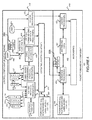
Figure 3 includes flow diagrams of example methods for implementing microBFD (or some other protocol, such as some other protocol for forwarding detection over member links of a grouping) and duplicate address detection (DAD, or some other address verification protocol) in a manner consistent with the present teachings. -
Figure 4 is a block diagram of an example router on which the present teachings may be implemented. -
Figure 5 is a block diagram of example distributed application specific integrated circuits ("ASICs") that may be provided in the example router ofFigure 4 . -
Figures 6A and 6B illustrate example packet forwarding operations of the example distributed ASICs ofFigure 5 . -
Figure 7 is a flow diagram of an example packet forwarding method that may be implemented on any of the example routers ofFigures 4 and5 . -
Figure 8 is a block diagram of an example processor-based system which may be use to execute the example methods consistent with the present teachings. - The present teachings may provide novel methods, apparatus, message formats, and/or data structures for allowing microBFD sessions to continue to run over member links of a LAG (using anIPv6 address that previously was checked by DAD) even when the LAG interface is DOWN (but not all member links of the LAG are DOWN and the LAG's IPv6 address becomes TENTATIVE). DAD may be run for the address configured for the microBFD once the individual link is in DISTRIBUTING or STANDBY state, and microBFD may be triggered (or started) once the DAD for that address completes successfully. The following description is presented to enable one skilled in the art to make and use the techniques of the present teachings, and is provided in the context of particular applications and their requirements. Thus, the following description of embodiments consistent with the present teachings provides illustration and description, but is not intended to be exhaustive or to be limiting to the precise form disclosed. Various modifications to the disclosed embodiments will be apparent to those skilled in the art, and the general principles set forth below may be applied to other embodiments and applications. For example, although a series of acts may be described with reference to a flow diagram, the order of acts may differ in other implementations when the performance of one act is not dependent on the completion of another act. Further, non-dependent acts may be performed in parallel. No element, act or instruction used in the description should be construed as critical or essential unless explicitly described as such. Also, as used herein, the article "a" is intended to include one or more items. Where only one item is intended, the term "one" or similar language is used. Thus, the present teachings are not intended to be limited to the embodiments shown and the inventors regard their developments as any patentable subject matter described.
-
Figure 3 includes flow diagrams ofexample methods - In the
example method 300, when a member link state is either DISTRIBUTING or STANDBY (Event 305), an IPv6 address configured for the link to run microBFD over the LAG is received (Block 310) and usability of the IPv6 address (which may have been marked as "TENTATIVE" as indicated by block 315) for the microBFD session is requested from theexample DAD method 350. (Block 320) - Referring to the
example DAD method 350, responsive to receipt of the IPv6 address usability request, theexample DAD method 350 performs different acts depending on the state of the IPv6 address. (Event 352 and State 355) If the IPv6 address is "READY" (left branch of State 355), a positive acknowledgement is sent back to the requestor (Block 372) and themethod 350 is left (RETURN node 399). If the IPv6 address is "DUPLICATE", a negative acknowledgement is sent back to the requestor (Block 382) and themethod 350 is left (RETURN node 399). Finally, if the IPv6 address is "TENTATIVE", the request is processed to determine_whether or not the IPv6 address is useable. That is, if the IPv6 address is in "TENTATIVE" state, themethod 350 will start a duplicate address detection process for the IPv6 address of the LAG. (Block 360) Once the DAD is complete and succeeds (left branch of Event 365), then the IPv6 address is marked as "READY" (Block 370), a positive acknowledgement is sent back to the requestor (Block 372) and themethod 350 is left (RETURN node 399). If, on the other hand, the DAD is complete and fails (right branch of Event 365), the address is marked "DUPLICATE" (Block 380), a negative acknowledgement is sent back to the requestor (Block 382) and themethod 350 is left (RETURN node 399). - Referring back to the
example microBFD method 300, if a positive acknowledgement is received from the DAD method 350 (right branch of Event 325), the microBFD session is started over that member link using the "READY" IPv6 address (Block 335) before themethod 300 is left (Return node 340). Otherwise, if a negative acknowledgement is received from the DAD method 350 (left branch of Event 325), the LAG is marked as "ERROR-Disabled" (Block 33) before themethod 300 is left (Return node 340). - Finally, in some implementations of link aggregation groups, the LAG interface is brought DOWN when a predetermined (e.g., configurable) minimum number of member links of the LAG are not available. However, even though the LAG interface is down, example embodiments permit microBFD sessions to be run (or to continue to run) over those member links that are UP, using the IPv6 address. More specifically, referring to
example method 350, if a member link of the LAG goes DOWN (right branch of Event 352), it is determined whether or not the LAG interface is to be brought DOWN. To reiterate, in some implementations, the LAG interface is brought DOWN when the minimum number of member links of the LAG are not available. If the LAG interface is not DOWN (No branch of Decision 385), themethod 350 is left (Return Node 399), in which case, any UP member links of the LAG are able to continue running microBFD. If, on the other hand, the LAG interface is DOWN (Yes branch of Decision 385), then it is determined whether or not all member links of the LAG are DOWN. If, it is determined that not all of the member links of the LAG are DOWN (No branch of Decision 390), themethod 350 is left (Return Node 399), in which case, any UP member links of the LAG are permitted to continue running microBFD. If, on the other hand, it is determined that all of the member links of the LAG are DOWN (Yes branch of Decision 390), then the IPv6 address configured for the microBFD over the LAG is marked as TENTATIVE (Block 395), in which case none of the member links of the LAG will run microBFD, and themethod 350 is left (Return Node 399). - Consistent with the foregoing
example method 350, the IPv6 address which is marked for microBFD sessions would be marked as to "TENTATIVE" only when all of the member links of the LAG are DOWN; not necessarily when the LAG interface goes DOWN. When a member link comes UP, the example methods described above may be used to run DAD on the IPv6 address. - As just discussed above, and referring to
Figure 4 , someexample routers 400 include a control component (e.g., routing engine) 410 and a packet forwarding component (e.g., a packet forwarding engine) 490. - The
control component 410 may include an operating system (OS)kernel 420, routing protocol process(es) 430, label-based forwarding protocol process(es) 440, interface process(es) 450, user interface (e.g., command line interface) process(es) 460, and chassis process(es) 470, and may store routing table(s) 439,label forwarding information 445, and forwarding (e.g., route-based and/or label-based) table(s) 480. As shown, the routing protocol process(es) 430 may support routing protocols such as the routing information protocol ("RIP") 431, the intermediate system-to-intermediate system protocol ("IS-IS") 432, the open shortest path first protocol ("OSPF") 433, the enhanced interior gateway routing protocol ("EIGRP") 434 and the boarder gateway protocol ("BGP") 435, and the label-based forwarding protocol process(es) 440 may support protocols such asBGP 435, the label distribution protocol ("LDP") 436 and the resource reservation protocol ("RSVP") 437. One or more components (not shown) may permit a user 465 to interact with the user interface process(es) 460. Similarly, one or more components (not shown) may permit an external device to interact with one or more of the router protocol process(es) 430, the label-based forwarding protocol process(es) 440, the interface process(es) 450, and the chassis process(es) 470, viaSNMP 485, and such processes may send information to an external device viaSNMP 485. - The
packet forwarding component 490 may include amicrokernel 492, interface process(es) 493, distributed application specific integrated circuits ("ASICs") 494, chassis process(es) 495 and forwarding (e.g., route-based and/or label-based) table(s) 496. - In the
example router 400 ofFigure 4 , thecontrol component 410 handles tasks such as performing routing protocols, performing label-based forwarding protocols, control packet processing, etc., which frees thepacket forwarding component 490 to forward received packets quickly. That is, received control packets (e.g., routing protocol packets and/or label-based forwarding protocol packets) are not fully processed on thepacket forwarding component 490 itself, but are passed to thecontrol component 410, thereby reducing the amount of work that thepacket forwarding component 490 has to do and freeing it to process packets to be forwarded efficiently. Thus, thecontrol component 410 is primarily responsible for running routing protocols and/or label-based forwarding protocols, maintaining the routing tables and/or label forwarding information, sending forwarding table updates to thepacket forwarding component 490, and performing system management. Theexample control component 410 may handle routing protocol packets, provide a management interface, provide configuration management, perform accounting, and provide alarms. Theprocesses OS kernel 420. That is, nearly all of the processes communicate directly with theOS kernel 420. Using modular software that cleanly separates processes from each other isolates problems of a given process so that such problems do not impact other processes that may be running. Additionally, using modular software facilitates easier scaling. - Still referring to
Figure 4 , theexample OS kernel 420 may incorporate an application programming interface ("API") system for external program calls and scripting capabilities. Thecontrol component 410 may be based on an Intel PCI platform running the OS from flash memory, with an alternate copy stored on the router's hard disk. TheOS kernel 420 is layered on the Intel PCI platform and establishes communication between the Intel PCI platform and processes of thecontrol component 410. TheOS kernel 420 also ensures that the forwarding tables 496 in use by thepacket forwarding component 490 are in sync with those 480 in thecontrol component 410. Thus, in addition to providing the underlying infrastructure to controlcomponent 410 software processes, theOS kernel 420 also provides a link between thecontrol component 410 and thepacket forwarding component 490. - Referring to the routing protocol process(es) 430 of
Figure 4 , this process(es) 430 provides routing and routing control functions within the platform. In this example, theRIP 431,ISIS 432,OSPF 433 and EIGRP 434 (and BGP 435) protocols are provided. Naturally, other routing protocols may be provided in addition, or alternatively. Similarly, the label-based forwarding protocol process(es) 440 provides label forwarding and label control functions. In this example, theLDP 436 and RSVP 437 (and BGP 435) protocols are provided. Naturally, other label-based forwarding protocols (e.g., MPLS) may be provided in addition, or alternatively. In theexample router 400, the routing table(s) 439 is produced by the routing protocol process(es) 430, while thelabel forwarding information 445 is produced by the label-based forwarding protocol process(es) 440. - Still referring to
Figure 4 , the interface process(es) 450 performs configuration of the physical interfaces (Recall, e.g., 416 and 426 ofFigure 4 .) and encapsulation. - The
example control component 410 may provide several ways to manage the router. For example, it 410 may provide a user interface process(es) 460 which allows a system operator 465 to interact with the system through configuration, modifications, and monitoring. TheSNMP 485 allows SNMP-capable systems to communicate with the router platform. This also allows the platform to provide necessary SNMP information to external agents. For example, theSNMP 485 may permit management of the system from a network management station running software, such as Hewlett-Packard's Network Node Manager (HP-NNM), through a framework, such as Hewlett-Packard's OpenView. Accounting of packets (generally referred to as traffic statistics) may be performed by thecontrol component 410, thereby avoiding slowing traffic forwarding by thepacket forwarding component 490. - Although not shown, the
example router 400 may provide for out-of-band management, RS-232 DB9 ports for serial console and remote management access, and tertiary storage using a removable PC card. Further, although not shown, a craft interface positioned on the front of the chassis provides an external view into the internal workings of the router. It can be used as a troubleshooting tool, a monitoring tool, or both. The craft interface may include LED indicators, alarm indicators, control component ports, and/or a display screen. Finally, the craft interface may provides interaction with a command line interface (CLI) 460 via a console port, an auxiliary port, and/or a management Ethernet port - The
packet forwarding component 490 is responsible for properly outputting received packets as quickly as possible. If there is no entry in the forwarding table for a given destination or a given label and thepacket forwarding component 490 cannot perform forwarding by itself, it 490 may send the packets bound for that unknown destination off to thecontrol component 410 for processing. The examplepacket forwarding component 490 is designed to performLayer 2 andLayer 3 switching, route lookups, and rapid packet forwarding. - As shown in
Figure 4 , the examplepacket forwarding component 490 has an embeddedmicrokernel 492, interface process(es) 493, distributedASICs 494, and chassis process(es) 495, and stores a forwarding (e.g., route-based and/or label-based) table(s) 496. Themicrokernel 492 interacts with the interface process(es) 493 and the chassis process(es) 495 to monitor and control these functions. The interface process(es) 492 has direct communication with theOS kernel 420 of thecontrol component 410. This communication includes forwarding exception packets and control packets to thecontrol component 410, receiving packets to be forwarded, receiving forwarding table updates, providing information about the health of thepacket forwarding component 490 to thecontrol component 410, and permitting configuration of the interfaces from the user interface (e.g., CLI) process(es) 460 of thecontrol component 410. The stored forwarding table(s) 496 is static until a new one is received from thecontrol component 410. The interface process(es) 493 uses the forwarding table(s) 496 to look up next-hop information. The interface process(es) 493 also has direct communication with the distributedASICs 494. Finally, the chassis process(es) 495 may communicate directly with themicrokernel 492 and with the distributedASICs 494. - Referring back to distributed
ASICs 494 ofFigure 4 ,Figure 5 is an example of how the ASICS may be distributed in thepacket forwarding component 490 to divide the responsibility of packet forwarding. As shown inFigure 5 , the ASICs of thepacket forwarding component 490 may be distributed on physical interface cards ("PICs") 510, flexible PIC concentrators ("FPCs") 520, a midplane orbackplane 530, and a system control board(s) 540 (for switching and/or forwarding). Switching fabric is also shown as a system switch board ("SSB"), or a switching and forwarding module ("SFM") 550. Each of thePICs 510 includes one or more PIC I/O managers 515. Each of theFPCs 520 includes one or more I/O managers 522, each with an associatedmemory 524. The midplane/backplane 530 includesbuffer managers system control board 540 includes aninternet processor 542 and an instance of the forwarding table 544 (Recall, e.g., 496 ofFigure 4 ). - Still referring to
Figure 5 , thePICs 510 contain the interface ports. EachPIC 510 may be plugged into anFPC 520. Eachindividual PIC 510 may contain an ASIC that handles media-specific functions, such as framing or encapsulation. Someexample PICs 510 provide SDH/SONET, ATM, Gigabit Ethernet, Fast Ethernet, and/or DS3/E3 interface ports. - An
FPC 520 can contain from one ormore PICs 510, and may carry the signals from thePICs 510 to the midplane/backplane 530 as shown inFigure 5 . - The midplane/
backplane 530 holds the line cards. The line cards may connect into the midplane /backplane 530 when inserted into the example router's chassis from the front. The control component (e.g., routing engine) 410 may plug into the rear of the midplane/backplane 530 from the rear of the chassis. The midplane/backplane 530 may carry electrical (or optical) signals and power to each line card and to thecontrol component 410. - The
system control board 540 may perform forwarding lookup. It 540 may also communicate errors to the routing engine. Further, it 540 may also monitor the condition of the router based on information it receives from sensors. If an abnormal condition is detected, thesystem control board 540 may immediately notify thecontrol component 410. - Referring to
Figures 5 ,6A and 6B , in some exemplary routers, each of the PICs 510,510' contains at least one I/O manager ASIC 515 responsible for media-specific tasks, such as encapsulation. The packets pass through these I/O ASICs on their way into and out of the router. The I/O manager ASIC 515 on the PIC 510,510' is responsible for managing the connection to the I/O manager ASIC 522 on the FPC 520,520' , managing link-layer framing and creating the bit stream, performing cyclical redundancy checks (CRCs), and detecting link-layer errors and generating alarms, when appropriate. TheFPC 520 includes another I/O manager ASIC 522. This ASIC 522 takes the packets from thePICs 510 and breaks them into (e.g., 64-byte) memory blocks. This FPC I/O manager ASIC 522 sends the blocks to a first distributed buffer manager (DBM) 535a', decoding encapsulation and protocol-specific information, counting packets and bytes for each logical circuit, verifying packet integrity, and applying class of service (CoS) rules to packets. At this point, the packet is first written to memory. More specifically, theexample DBM ASIC 535a' manages and writes packets to the sharedmemory 524 across allFPCs 520. In parallel, thefirst DBM ASIC 535a' also extracts information on the destination of the packet and passes this forwarding-related information to theInternet processor 542/542'. TheInternet processor 542/542' performs the route lookup using the forwarding table 544 and sends the information over to asecond DBM ASIC 535b'. TheInternet processor ASIC 542/542' also collects exception packets (i.e., those without a forwarding table entry) and sends them to thecontrol component 410. Thesecond DBM ASIC 535b' then takes this information and the 64-byte blocks and forwards them to the I/O manager ASIC 522 of theegress FPC 520/520' (or multiple egress FPCs, in the case of multicast) for reassembly. (Thus, the DBM ASICs 535a' and 535b' are responsible for managing thepacket memory 524 distributed across allFPCs 520/520', extracting forwarding-related information from packets, and instructing the FPC where to forward packets.) - The I/O manager ASIC 522 on the
egress FPC 520/520' may perform some value-added services. In addition to incrementing time to live (TTL) values and re-encapsulating the packet for handling by thePIC 510, it can also apply class-of-service (CoS) rules. To do this, it may queue a pointer to the packet in one of the available queues, each having a share of link bandwidth, before applying the rules to the packet. Queuing can be based on various rules. Thus, the I/O manager ASIC 522 on theegress FPC 520/520' may be responsible for receiving the blocks from thesecond DBM ASIC 535b', incrementing TTL values, queuing a pointer to the packet, if necessary, before applying CoS rules, re-encapsulating the blocks, and sending the encapsulated packets to the PIC I/O manager ASIC 515. -
Figure 7 is a flow diagram of anexample method 700 for providing packet forwarding in the example router. The main acts of themethod 700 are triggered when a packet is received on an ingress (incoming) port or interface. (Event 710) The types of checksum and frame checks that are required by the type of medium it serves are performed and the packet is output, as a serial bit stream. (Block 720) The packet is then decapsulated and parsed into (e.g., 64-byte) blocks. (Block 730) The packets are written to buffer memory and the forwarding information is passed on the Internet processor. (Block 740) The passed forwarding information is then used to lookup a route in the forwarding table. (Block 750) Note that the forwarding table can typically handle unicast packets that do not have options (e.g., accounting) set, and multicast packets for which it already has a cached entry. Thus, if it is determined that these conditions are met (YES branch of Decision 760), the packet forwarding component finds the next hop and egress interface, and the packet is forwarded (or queued for forwarding) to the next hop via the egress interface (Block 770) before themethod 700 is left (Node 790) Otherwise, if these conditions are not met (NO branch of Decision 760), the forwarding information is sent to thecontrol component 410 for advanced forwarding resolution (Block 780) before themethod 700 is left (Node 790). - Referring back to block 770, the packet may be queued. Actually, as stated earlier with reference to
Figure 5 , a pointer to the packet may be queued. The packet itself may remain in the shared memory. Thus, all queuing decisions and CoS rules may be applied in the absence of the actual packet. When the pointer for the packet reaches the front of the line, the I/O manager ASIC 522 may send a request for the packet to thesecond DBM ASIC 535b. TheDBM ASIC 535 reads the blocks from shared memory and sends them to the I/O manager ASIC 522 on theFPC 520, which then serializes the bits and sends them to the media-specific ASIC of the egress interface. The I/O manager ASIC 515 on theegress PIC 510 may apply the physical-layer framing, perform the CRC, and send the bit stream out over the link. - Referring back to block 780 of
Figure 7 , as well asFigure 5 , regarding the transfer of control and exception packets, thesystem control board 540 handles nearly all exception packets. For example, thesystem control board 540 may pass exception packets to thecontrol component 410. - Although example embodiments are described as being implemented on the example routers of
Figures 2 or4 (See especially the microBFD, IPv6 andDAD processes 499a and/or 499b ofFigure 4 .), embodiments may be implemented on communications network nodes (e.g., routers, switches, etc.) having different architectures. More generally, embodiments consistent with the present teachings may be implemented on an example system 900 as illustrated onFigure 8 . -
Figure 8 is a block diagram of anexemplary machine 800 that may perform one or more of the processes described, and/or store information used and/or generated by such processes. Theexemplary machine 800 includes one ormore processors 810, one or more input/output interface units 830, one ormore storage devices 820, and one or more system buses and/ornetworks 840 for facilitating the communication of information among the coupled elements. One ormore input devices 832 and one ormore output devices 834 may be coupled with the one or more input/output interfaces 830. The one ormore processors 810 may execute machine-executable instructions (e.g., C or C++ running on is a Unix operating system, such as one of the Berkeley Software Distribution ("BSD") derivatives developed and distributed by the Computer Systems Research Group ("CSRG") of the University of California, Berkeley, the Linux operating system widely available from a number of vendors such as Red Hat, Inc. of Durham, North Carolina, etc.) to effect one or more aspects of the present teachings. At least a portion of the machine executable instructions may be stored (temporarily or more permanently) on the one ormore storage devices 820 and/or may be received from an external source via one or moreinput interface units 830. The machine executable instructions may be stored as various software modules, each module performing one or more operations. Functional software modules are examples of components of the presently taught approaches. - In some embodiments, the
processors 810 may be one or more microprocessors and/or ASICs. Thebus 840 may include a system bus. Thestorage devices 820 may include system memory, such as read only memory (ROM) and/or random access memory (RAM). Thestorage devices 820 may also include a hard disk drive for reading from and writing to a hard disk, a magnetic disk drive for reading from or writing to a (e.g., removable) magnetic disk, an optical disk drive for reading from or writing to a removable (magneto-) optical disk such as a compact disk or other (magneto-) optical media, solid-state non-volatile storage, or some other computer readable medium. - Some example embodiments may also be provided as a machine-readable medium for storing the machine-executable instructions. The machine-readable medium may be transient or non-transitory and may include, but is not limited to, flash memory, optical disks, CD-ROMs, DVD ROMs, RAMs, EPROMs, EEPROMs, magnetic or optical cards or any other type of machine-readable media suitable for storing electronic instructions or as signals or any other form of transmission medium suitable for transferring electronic instructions. For example, example embodiments may be downloaded as a computer program which may be transferred from a remote computer (e.g., a server) to a requesting computer (e.g., a client) by way of a communication link (e.g., a modem or network connection) over a communication medium and then stored on a storage medium. The machine-readable medium may also be referred to as a processor-readable medium.
- Example embodiments can be implemented in hardware, such as one or more field programmable gate arrays ("FPGAs"), one or more integrated circuits such as ASICs, one or more network processors, etc. Alternatively, or in addition, embodiments can be implemented as stored program instructions executed by a processor. Such hardware and/or software might be provided in an addressed data (e.g., packet, cell, etc.) forwarding device (e.g., a switch, a router, etc.), a laptop computer, desktop computer, a tablet computer, a mobile phone, or any device that has computing and networking capabilities.
- As understood by those having ordinary skill in the art, as used in this application, a "unit," "component," "element," "module," "device," "mechanism," "member," or "process" may be implemented as circuitry, such as integrated circuits, ASICs, field programmable logic (or gate) arrays ("FPLAs"), etc., and/or software implemented on a processor, such as a microprocessor.
- Although some example embodiments consistent with the present teachings were described as being used in the context of microBFD, other example embodiments consistent with the present teachings can be used in the context of other processes or protocols that need to check the usability of an address, such as an IPv6 address.
- Although some example embodiments were described as being used with a duplicate address detection ("DAD") process, other example embodiments can be used in the context of other address checking processes.
- Although some example embodiments discussed link states such as DISTRIBUTING, STANDBY, UP and DOWN, and address states as READY, TENTATIVE or DUPLICATE, these are to broadly interpreted to include states that are functionally equivalent.
- Further examples consistent with and forming a part of the present teachings are set out in the following numbered clauses:
-
Clause 1 In a data forwarding device supporting an aggregated link including a plurality of member links, a method for performing a protocol on the member links of the aggregated link that uses an address of the aggregated link, the method comprising: checking a usability of the address; responsive to a determination that the address is usable, running the protocol on the member links; responsive to a determination that the aggregated link is DOWN, permitting the protocol to continue running on any of the member links that are UP; and responsive to a determination that all of the member links of the aggregated link are DOWN, marking the address so that its usability needs to be rechecked, and - discontinuing the protocol on the member links, and otherwise, responsive to a determination that not all of the member links of the aggregated link are DOWN, permitting the protocol to continue running on any member links that are UP.
-
Clause 2 The method ofclause 1 wherein the protocol is a micro Bidirectional Forwarding Detection ("microBFD") protocol. -
Clause 3 The method ofclause 2 wherein the address is an Internet Protocol version 6 ("IPv6") address. - Clause 4 The method of
clause 3 wherein the usability of the address is checked using a duplicate address detection ("DAD") protocol. - Clause 5 The method of any preceding clause wherein the aggregated link is managed using a Link Aggregation Control Protocol" ("LACP").
- Clause 6 The method of clause 5 wherein the address is an Internet Protocol version 6 ("IPv6") address.
- Clause 7 The method of clause 6 or 7 wherein the usability of the address is checked using a duplicate address detection ("DAD") protocol.
- Clause 8 The method of any preceding clause wherein the address is an Internet Protocol version 6 ("IPv6") address.
- Clause 9 The method of clause 8 wherein the usability of the address is checked using a duplicate address detection ("DAD") protocol.
- Clause 10 The method of any preceding clause wherein each of the member links include (1) a first interface, (2) a second interface, and (3) a physical link coupling the first and second interfaces.
- Clause 11 The method of any preceding clause wherein each of the member links include (1) a first interface, (2) a second interface, and (3) a wireless link coupling the first and second interfaces.
- Clause 12 A data forwarding device comprising: a plurality of interfaces of a plurality of member links defining an aggregated link; at least one processor; and a storage device storing processor-executable instructions which, when executed by the at least one processor, cause the at least one processor to perform a method for performing a protocol on the member links of the aggregated link that uses an address of the aggregated link, the method including checking a usability of the address;
- responsive to a determination that the address is usable, running the protocol on the member links;
- responsive to a determination that the aggregated link is DOWN, permitting the protocol to continue running on any of the member links that are UP; and responsive to a determination that all of the member links of the aggregated link are DOWN, marking the address so that its usability needs to be rechecked,
- and discontinuing the protocol on the member links, and otherwise, responsive to a determination that not all of the member links of the aggregated link are DOWN, permitting the protocol to continue running on any member links that are UP.
- Clause 13 The data forwarding device of clause 12 wherein the protocol is a micro Bidirectional Forwarding Detection ("microBFD") protocol.
- Clause 14 The data forwarding device of clause 13 or 14 wherein the address is an Internet Protocol version 6 ("IPv6") address.
- Clause 15 The data forwarding device of clause 14 wherein the usability of the address is checked using a duplicate address detection ("DAD") protocol.
- Clause 16 The data forwarding device of any of clauses 12 to 15 wherein the aggregated link is managed using a Link Aggregation Control Protocol" ("LACP").
- Clause 17 The data forwarding device of clause 16 wherein the address is an Internet Protocol version 6 ("IPv6") address.
- Clause 18 The data forwarding device of clause 17wherein the usability of the address is checked using a duplicate address detection ("DAD") protocol.
- Clause 19 The data forwarding device of any of clauses 12 to 18 wherein the address is an Internet Protocol version 6 ("IPv6") address.
- Clause 20 The data forwarding device of clause 19 wherein the usability of the address is checked using a duplicate address detection ("DAD") protocol.
- Clause 21 A storage device storing processor-executable instructions which, when executed by the at least one processor of a data forwarding device supporting an aggregated link including a plurality of member links, cause the at least one processor to perform a method for performing a protocol on the member links of the aggregated link that uses an address of the aggregated link, the method including checking a usability of the address;
- Clause 22 responsive to a determination that the address is usable, running the protocol on the member links; responsive to a determination that the aggregated link is DOWN, permitting the protocol to continue running on any of the member links that are UP; and responsive to a determination that all of the member links of the aggregated link are DOWN, marking the address so that its usability needs to be rechecked, and discontinuing the protocol on the member links, and otherwise, responsive to a determination that not all of the member links of the aggregated link are DOWN, permitting the protocol to continue running on any member links that are UP.
- Therefore, from one perspective, there has been described an approach to addressing a problem of being unable to run microBFD using an IPv6 address over any member links of a
layer 2 LAG when the LAG is DOWN (and its IPv6 address becomes or is TENTATIVE), by running DAD for the address configured for the microBFD once the individual link is in DISTRIBUTING or STANDBY state and triggering (or starting) microBFD once the DAD for that address completes successfully. Further, member links of the LAG may be permitted to continue running microBFD even if the LAG interface is DOWN and even if some other member links (but not all member links) of the LAG are DOWN. - In platforms that support running duplicate address detection on link flaps, in a regular case the address would be marked TENTATIVE when a
layer 3 link goes down, thereby forcing DAD to be run on that address when the link comes up. However in the case of microBFD this also poses conformance issues. The LAG interface may be brought DOWN when a predetermined (e.g., configurable) minimum number of LAG member links are not available. However, even though the LAG interface is down, example embodiments permit microBFD sessions to be run (or to continue to run) over those member links that are UP using the IPv6 address of the LAG. Example embodiments may do so as follows. The address which is marked for microBFD sessions would be marked as to TENTATIVE only when the last member link of the LAG goes DOWN (i.e., when all member links are DOWN); not necessarily when the LAG interface goes DOWN. When a member link comes UP, the example methods described above may be used to run DAD on the IPv6 address. Example embodiments provide or facilitate a method to run DAD on addresses (e.g., source and/or destination IPv6 addresses) used for microBFD sessions and ensure that the same is in conformance with the RFC (2462).
Claims (13)
- In a data forwarding device supporting an aggregated link including a plurality of member links, a method for performing a protocol on the member links of the aggregated link that uses an address of the aggregated link, the method comprising:checking a usability of the address;responsive to a determination that the address is usable, running the protocol on the member links;responsive to a determination that the aggregated link is DOWN, permitting the protocol to continue running on any of the member links that are UP; andresponsive to a determination that all of the member links of the aggregated link are DOWN, marking the address so that its usability needs to be rechecked, and discontinuing the protocol on the member links,and otherwise, responsive to a determination that not all of the member links of the aggregated link are DOWN, permitting the protocol to continue running on any member links that are UP.
- The method of claim 1 wherein the protocol is a micro Bidirectional Forwarding Detection ("microBFD") protocol.
- The method of claim 1 or 2 wherein the aggregated link is managed using a Link Aggregation Control Protocol" ("LACP").
- The method of any preceding claim wherein the address is an Internet Protocol version 6 ("IPv6") address.
- The method of claim 4 wherein the usability of the address is checked using a duplicate address detection ("DAD") protocol.
- The method of any preceding claim wherein each of the member links include (1) a first interface, (2) a second interface, and (3) a physical link coupling the first and second interfaces.
- The method of any preceding claim wherein each of the member links include (1) a first interface, (2) a second interface, and (3) a wireless link coupling the first and second interfaces.
- A data forwarding device comprising:a plurality of interfaces of a plurality of member links defining an aggregated link;at least one processor; anda storage device storing processor-executable instructions which, when executed by the at least one processor, cause the at least one processor to perform a method for performing a protocol on the member links of the aggregated link that uses an address of the aggregated link, the method includingchecking a usability of the address;responsive to a determination that the address is usable, running the protocol on the member links;responsive to a determination that the aggregated link is DOWN, permitting the protocol to continue running on any of the member links that are UP; andresponsive to a determination that all of the member links of the aggregated link are DOWN,marking the address so that its usability needs to be rechecked, anddiscontinuing the protocol on the member links,and otherwise, responsive to a determination that not all of the member links of the aggregated link are DOWN, permitting the protocol to continue running on any member links that are UP.
- The data forwarding device of claim 8 wherein the protocol is a micro Bidirectional Forwarding Detection ("microBFD") protocol.
- The data forwarding device of claim 8 or 9 wherein the aggregated link is managed using a Link Aggregation Control Protocol" ("LACP").
- The data forwarding device of any of claims 8 to 10 wherein the address is an Internet Protocol version 6 ("IPv6") address.
- The data forwarding device of claim 11 wherein the usability of the address is checked using a duplicate address detection ("DAD") protocol.
- A computer-readable medium storing processor-executable instructions which, when executed by the at least one processor of a data forwarding device supporting an aggregated link including a plurality of member links, cause the at least one processor to perform the method of any of claims 1 to 7 or cause the forwarding device to become configured as the forwarding device of any of claim 18 to 12.
Applications Claiming Priority (1)
| Application Number | Priority Date | Filing Date | Title |
|---|---|---|---|
| US15/091,393 US9929897B2 (en) | 2016-04-05 | 2016-04-05 | Performing a protocol, such as micro bidirectional forwarding detection, on member links of an aggregated link that uses an address of the aggregated link |
Publications (2)
| Publication Number | Publication Date |
|---|---|
| EP3229406A1 true EP3229406A1 (en) | 2017-10-11 |
| EP3229406B1 EP3229406B1 (en) | 2019-01-30 |
Family
ID=56137210
Family Applications (1)
| Application Number | Title | Priority Date | Filing Date |
|---|---|---|---|
| EP16175131.8A Active EP3229406B1 (en) | 2016-04-05 | 2016-06-17 | Performing a protocol, such as micro bidirectional forwarding detection, on member links of an aggregated link that uses an address of the aggregated link |
Country Status (3)
| Country | Link |
|---|---|
| US (1) | US9929897B2 (en) |
| EP (1) | EP3229406B1 (en) |
| CN (1) | CN107295056B (en) |
Families Citing this family (12)
| Publication number | Priority date | Publication date | Assignee | Title |
|---|---|---|---|---|
| US10257019B2 (en) * | 2015-12-04 | 2019-04-09 | Arista Networks, Inc. | Link aggregation split-brain detection and recovery |
| US10616046B2 (en) * | 2017-03-28 | 2020-04-07 | Arista Networks, Inc. | System and method of handling a fault detection mechanism during a control plane failover |
| KR101877004B1 (en) * | 2017-09-29 | 2018-07-10 | 주식회사 쏠리드 | Openflow based distributed antenna system |
| CN108400911B (en) * | 2018-02-27 | 2021-04-09 | 盛科网络(苏州)有限公司 | Device and method for realizing Micro-BFD protocol |
| US10805193B1 (en) * | 2019-04-30 | 2020-10-13 | Juniper Networks, Inc. | Faster fault-detection mechanism, for example using bidirectional forwarding detection (BFD), on network nodes and/or hosts multihomed using a link aggregation group (LAG) |
| CN111356181B (en) * | 2020-02-25 | 2023-04-28 | 杭州迪普信息技术有限公司 | Traffic forwarding method, traffic forwarding device, network equipment and computer readable storage medium |
| US11641336B2 (en) * | 2020-05-29 | 2023-05-02 | Dell Products L.P. | Lightweight host multihoming |
| US11516136B2 (en) * | 2020-06-04 | 2022-11-29 | Juniper Networks, Inc. | Distributed node processing of network traffic |
| CN112804116B (en) * | 2020-06-30 | 2023-02-17 | 中兴通讯股份有限公司 | Link detection method, electronic device and computer readable medium |
| US11671351B2 (en) * | 2020-12-04 | 2023-06-06 | Juniper Networks, Inc. | Maintaining a set of links associated with a link aggregation group to facilitate provisioning or updating of a customer edge device |
| CN112737944B (en) * | 2020-12-25 | 2022-07-08 | 浪潮思科网络科技有限公司 | Bfd-based peer-link state detection method, device and medium |
| CN113472648B (en) * | 2021-06-18 | 2023-10-24 | 新华三信息安全技术有限公司 | Bidirectional Forwarding Detection (BFD) method and device and network equipment |
Citations (4)
| Publication number | Priority date | Publication date | Assignee | Title |
|---|---|---|---|---|
| US7561527B1 (en) | 2003-05-02 | 2009-07-14 | David Katz | Bidirectional forwarding detection |
| US20130191463A1 (en) * | 2012-01-20 | 2013-07-25 | Cisco Technology, Inc. | Managing address validation states in switches snooping ipv6 |
| US8774179B1 (en) * | 2007-01-19 | 2014-07-08 | Juniper Networks, Inc. | Member link status change handling for aggregate interfaces |
| US20150381466A1 (en) * | 2014-06-25 | 2015-12-31 | Broadcom Corporation | Micro-OAM for Link Groups |
Family Cites Families (14)
| Publication number | Priority date | Publication date | Assignee | Title |
|---|---|---|---|---|
| JP4840236B2 (en) * | 2007-04-12 | 2011-12-21 | 株式会社日立製作所 | Network system and node device |
| US8111611B2 (en) * | 2008-06-30 | 2012-02-07 | Cisco Technology, Inc. | Bidirectional forwarding detection on multilink bundled interfaces |
| US7921219B2 (en) * | 2008-08-19 | 2011-04-05 | Cisco Technology, Inc. | Maintaining protocol adjacency state with forwarding failure |
| US8861338B2 (en) * | 2010-06-30 | 2014-10-14 | Avaya Inc. | Routed split multilink trunking for IPv6 |
| US8913489B2 (en) * | 2010-08-04 | 2014-12-16 | Alcatel Lucent | System and method for virtual fabric link failure recovery |
| US20120281541A1 (en) * | 2011-05-04 | 2012-11-08 | Cisco Technology, Inc., A Corporation Of California | Signaling Describing the Operation of a Link Bundle |
| US9231838B2 (en) * | 2011-11-09 | 2016-01-05 | Telefonaktiebolaget L M Ericsson (Publ) | Method and apparatus for detecting and locating network connection failures |
| CN102820990B (en) * | 2012-02-29 | 2015-05-13 | 中兴通讯股份有限公司 | Method and device for switching service protection |
| CN102594610A (en) * | 2012-03-20 | 2012-07-18 | 福建星网锐捷网络有限公司 | Host election method after topology division as well as device and network equipment |
| US9191361B2 (en) * | 2012-11-26 | 2015-11-17 | King Fahd University Of Petroleum And Minerals | Authentication method for stateless address allocation in IPV6 networks |
| US20150350043A1 (en) * | 2013-01-23 | 2015-12-03 | Telefonaktiebolaget L M Ericsson (Publ) | Methods and arrangements for checking connectivity and detecting connectivity failure |
| CN103220189B (en) * | 2013-04-12 | 2017-02-08 | 杭州华三通信技术有限公司 | Multi-active detection (MAD) backup method and equipment |
| CN104394034B (en) * | 2014-12-04 | 2018-07-31 | 上海斐讯数据通信技术有限公司 | A kind of method and system based on LLDP protocol detection link aggregation configurations |
| CN104506546B (en) * | 2014-12-30 | 2018-06-15 | 新华三技术有限公司 | The bidirectional forwarding detection (BFD) method and device of a kind of aggregated links |
-
2016
- 2016-04-05 US US15/091,393 patent/US9929897B2/en active Active
- 2016-06-17 EP EP16175131.8A patent/EP3229406B1/en active Active
- 2016-09-30 CN CN201610875854.3A patent/CN107295056B/en active Active
Patent Citations (4)
| Publication number | Priority date | Publication date | Assignee | Title |
|---|---|---|---|---|
| US7561527B1 (en) | 2003-05-02 | 2009-07-14 | David Katz | Bidirectional forwarding detection |
| US8774179B1 (en) * | 2007-01-19 | 2014-07-08 | Juniper Networks, Inc. | Member link status change handling for aggregate interfaces |
| US20130191463A1 (en) * | 2012-01-20 | 2013-07-25 | Cisco Technology, Inc. | Managing address validation states in switches snooping ipv6 |
| US20150381466A1 (en) * | 2014-06-25 | 2015-12-31 | Broadcom Corporation | Micro-OAM for Link Groups |
Non-Patent Citations (2)
| Title |
|---|
| M. BHATIA ET AL: "RFC 7130 - Bidirectional Forwarding Detection (BFD) on Link Aggregation Group (LAG) Interfaces", 28 February 2014 (2014-02-28), pages 1 - 22, XP055333198, Retrieved from the Internet <URL:https://tools.ietf.org/html/rfc7130> [retrieved on 20170109] * |
| UNDERSTANDING INTEGRATED ROUTING AND BRIDGING (''IRB'') INTERFACES AND ROUTED VLAN INTERFACES (''RVI'') ON EX SERIES SWITCHES, Retrieved from the Internet <URL:http://www .juniper.net/techpubs/en_US/junos13.3/topics/concept/bridging-routed-vlan-interface.html> |
Also Published As
| Publication number | Publication date |
|---|---|
| CN107295056B (en) | 2020-10-16 |
| EP3229406B1 (en) | 2019-01-30 |
| US9929897B2 (en) | 2018-03-27 |
| US20170288946A1 (en) | 2017-10-05 |
| CN107295056A (en) | 2017-10-24 |
Similar Documents
| Publication | Publication Date | Title |
|---|---|---|
| EP3229406B1 (en) | Performing a protocol, such as micro bidirectional forwarding detection, on member links of an aggregated link that uses an address of the aggregated link | |
| US11876695B2 (en) | Path monitoring system (PMS) controller or ingress node based multiprotocal label switching (MPLS) ping and traceroute in inter-autonomous system (AS) segment routing (SR) networks | |
| EP3573293A1 (en) | Reducing or eliminating routing microloops in networks having a clos topology, such as data center clos networks employing the exterior border gateway protocol (ebgp) for example | |
| US8948008B2 (en) | Drop sensitive prefix (BGP path) attribute modification | |
| CN112565046B (en) | Synchronizing multicast router capabilities | |
| US9264348B2 (en) | Avoiding data traffic loss in an ethernet ring multihomed, in an active-standby manner, to a virtual private LAN service transport network | |
| EP3734915B1 (en) | Faster fault-detection mechanism using bidirectional forwarding detection (bfd), on network nodes and/or hosts multihomed using a link aggregation group (lag) | |
| CN110061912B (en) | Arbitrating mastership between redundant control planes of virtual nodes | |
| US10917337B1 (en) | Time to live (TTL) handing for segment routing ping/traceroute | |
| US11765077B1 (en) | Ping and traceroute in inter-autonomous system (AS) segment routing (SR) networks without requiring headend router or path monitoring system (PMS) controller knowledge of topology outside of origin AS | |
| US11070386B2 (en) | Controlling an aggregate number of unique PIM joins in one or more PIM join/prune messages received from a PIM neighbor | |
| EP3624401A1 (en) | Systems and methods for non-intrusive network performance monitoring | |
| US11057295B1 (en) | Loop avoidance and egress link protection with ethernet virtual private network (EVPN) fast reroute (FRR) | |
| US10454823B1 (en) | Packet processing in a routing instance that is distributed across at least two different routing stacks | |
| US10887282B1 (en) | Determining synchronization of filter rules (e.g., on iptable filter tables on Linux kernal) across firewall filter application restarts | |
| US10728137B1 (en) | Protocol independent multicast (“PIM”) fault tolerant designated router (“DR”) election | |
| CN113381930B (en) | Group load balancing for virtual router redundancy |
Legal Events
| Date | Code | Title | Description |
|---|---|---|---|
| PUAI | Public reference made under article 153(3) epc to a published international application that has entered the european phase |
Free format text: ORIGINAL CODE: 0009012 |
|
| STAA | Information on the status of an ep patent application or granted ep patent |
Free format text: STATUS: REQUEST FOR EXAMINATION WAS MADE |
|
| 17P | Request for examination filed |
Effective date: 20160715 |
|
| AK | Designated contracting states |
Kind code of ref document: A1 Designated state(s): AL AT BE BG CH CY CZ DE DK EE ES FI FR GB GR HR HU IE IS IT LI LT LU LV MC MK MT NL NO PL PT RO RS SE SI SK SM TR |
|
| AX | Request for extension of the european patent |
Extension state: BA ME |
|
| GRAP | Despatch of communication of intention to grant a patent |
Free format text: ORIGINAL CODE: EPIDOSNIGR1 |
|
| STAA | Information on the status of an ep patent application or granted ep patent |
Free format text: STATUS: GRANT OF PATENT IS INTENDED |
|
| INTG | Intention to grant announced |
Effective date: 20180808 |
|
| GRAJ | Information related to disapproval of communication of intention to grant by the applicant or resumption of examination proceedings by the epo deleted |
Free format text: ORIGINAL CODE: EPIDOSDIGR1 |
|
| STAA | Information on the status of an ep patent application or granted ep patent |
Free format text: STATUS: REQUEST FOR EXAMINATION WAS MADE |
|
| GRAR | Information related to intention to grant a patent recorded |
Free format text: ORIGINAL CODE: EPIDOSNIGR71 |
|
| GRAS | Grant fee paid |
Free format text: ORIGINAL CODE: EPIDOSNIGR3 |
|
| STAA | Information on the status of an ep patent application or granted ep patent |
Free format text: STATUS: GRANT OF PATENT IS INTENDED |
|
| GRAA | (expected) grant |
Free format text: ORIGINAL CODE: 0009210 |
|
| STAA | Information on the status of an ep patent application or granted ep patent |
Free format text: STATUS: THE PATENT HAS BEEN GRANTED |
|
| INTC | Intention to grant announced (deleted) | ||
| INTG | Intention to grant announced |
Effective date: 20181217 |
|
| AK | Designated contracting states |
Kind code of ref document: B1 Designated state(s): AL AT BE BG CH CY CZ DE DK EE ES FI FR GB GR HR HU IE IS IT LI LT LU LV MC MK MT NL NO PL PT RO RS SE SI SK SM TR |
|
| REG | Reference to a national code |
Ref country code: GB Ref legal event code: FG4D |
|
| REG | Reference to a national code |
Ref country code: CH Ref legal event code: EP |
|
| REG | Reference to a national code |
Ref country code: AT Ref legal event code: REF Ref document number: 1094104 Country of ref document: AT Kind code of ref document: T Effective date: 20190215 |
|
| REG | Reference to a national code |
Ref country code: IE Ref legal event code: FG4D |
|
| REG | Reference to a national code |
Ref country code: DE Ref legal event code: R096 Ref document number: 602016009573 Country of ref document: DE |
|
| REG | Reference to a national code |
Ref country code: LT Ref legal event code: MG4D |
|
| REG | Reference to a national code |
Ref country code: NL Ref legal event code: MP Effective date: 20190130 |
|
| PG25 | Lapsed in a contracting state [announced via postgrant information from national office to epo] |
Ref country code: PT Free format text: LAPSE BECAUSE OF FAILURE TO SUBMIT A TRANSLATION OF THE DESCRIPTION OR TO PAY THE FEE WITHIN THE PRESCRIBED TIME-LIMIT Effective date: 20190530 Ref country code: FI Free format text: LAPSE BECAUSE OF FAILURE TO SUBMIT A TRANSLATION OF THE DESCRIPTION OR TO PAY THE FEE WITHIN THE PRESCRIBED TIME-LIMIT Effective date: 20190130 Ref country code: NO Free format text: LAPSE BECAUSE OF FAILURE TO SUBMIT A TRANSLATION OF THE DESCRIPTION OR TO PAY THE FEE WITHIN THE PRESCRIBED TIME-LIMIT Effective date: 20190430 Ref country code: SE Free format text: LAPSE BECAUSE OF FAILURE TO SUBMIT A TRANSLATION OF THE DESCRIPTION OR TO PAY THE FEE WITHIN THE PRESCRIBED TIME-LIMIT Effective date: 20190130 Ref country code: PL Free format text: LAPSE BECAUSE OF FAILURE TO SUBMIT A TRANSLATION OF THE DESCRIPTION OR TO PAY THE FEE WITHIN THE PRESCRIBED TIME-LIMIT Effective date: 20190130 Ref country code: NL Free format text: LAPSE BECAUSE OF FAILURE TO SUBMIT A TRANSLATION OF THE DESCRIPTION OR TO PAY THE FEE WITHIN THE PRESCRIBED TIME-LIMIT Effective date: 20190130 Ref country code: LT Free format text: LAPSE BECAUSE OF FAILURE TO SUBMIT A TRANSLATION OF THE DESCRIPTION OR TO PAY THE FEE WITHIN THE PRESCRIBED TIME-LIMIT Effective date: 20190130 Ref country code: ES Free format text: LAPSE BECAUSE OF FAILURE TO SUBMIT A TRANSLATION OF THE DESCRIPTION OR TO PAY THE FEE WITHIN THE PRESCRIBED TIME-LIMIT Effective date: 20190130 |
|
| REG | Reference to a national code |
Ref country code: AT Ref legal event code: MK05 Ref document number: 1094104 Country of ref document: AT Kind code of ref document: T Effective date: 20190130 |
|
| PG25 | Lapsed in a contracting state [announced via postgrant information from national office to epo] |
Ref country code: HR Free format text: LAPSE BECAUSE OF FAILURE TO SUBMIT A TRANSLATION OF THE DESCRIPTION OR TO PAY THE FEE WITHIN THE PRESCRIBED TIME-LIMIT Effective date: 20190130 Ref country code: RS Free format text: LAPSE BECAUSE OF FAILURE TO SUBMIT A TRANSLATION OF THE DESCRIPTION OR TO PAY THE FEE WITHIN THE PRESCRIBED TIME-LIMIT Effective date: 20190130 Ref country code: BG Free format text: LAPSE BECAUSE OF FAILURE TO SUBMIT A TRANSLATION OF THE DESCRIPTION OR TO PAY THE FEE WITHIN THE PRESCRIBED TIME-LIMIT Effective date: 20190430 Ref country code: GR Free format text: LAPSE BECAUSE OF FAILURE TO SUBMIT A TRANSLATION OF THE DESCRIPTION OR TO PAY THE FEE WITHIN THE PRESCRIBED TIME-LIMIT Effective date: 20190501 Ref country code: IS Free format text: LAPSE BECAUSE OF FAILURE TO SUBMIT A TRANSLATION OF THE DESCRIPTION OR TO PAY THE FEE WITHIN THE PRESCRIBED TIME-LIMIT Effective date: 20190530 Ref country code: LV Free format text: LAPSE BECAUSE OF FAILURE TO SUBMIT A TRANSLATION OF THE DESCRIPTION OR TO PAY THE FEE WITHIN THE PRESCRIBED TIME-LIMIT Effective date: 20190130 |
|
| PG25 | Lapsed in a contracting state [announced via postgrant information from national office to epo] |
Ref country code: EE Free format text: LAPSE BECAUSE OF FAILURE TO SUBMIT A TRANSLATION OF THE DESCRIPTION OR TO PAY THE FEE WITHIN THE PRESCRIBED TIME-LIMIT Effective date: 20190130 Ref country code: SK Free format text: LAPSE BECAUSE OF FAILURE TO SUBMIT A TRANSLATION OF THE DESCRIPTION OR TO PAY THE FEE WITHIN THE PRESCRIBED TIME-LIMIT Effective date: 20190130 Ref country code: IT Free format text: LAPSE BECAUSE OF FAILURE TO SUBMIT A TRANSLATION OF THE DESCRIPTION OR TO PAY THE FEE WITHIN THE PRESCRIBED TIME-LIMIT Effective date: 20190130 Ref country code: DK Free format text: LAPSE BECAUSE OF FAILURE TO SUBMIT A TRANSLATION OF THE DESCRIPTION OR TO PAY THE FEE WITHIN THE PRESCRIBED TIME-LIMIT Effective date: 20190130 Ref country code: AL Free format text: LAPSE BECAUSE OF FAILURE TO SUBMIT A TRANSLATION OF THE DESCRIPTION OR TO PAY THE FEE WITHIN THE PRESCRIBED TIME-LIMIT Effective date: 20190130 Ref country code: RO Free format text: LAPSE BECAUSE OF FAILURE TO SUBMIT A TRANSLATION OF THE DESCRIPTION OR TO PAY THE FEE WITHIN THE PRESCRIBED TIME-LIMIT Effective date: 20190130 Ref country code: CZ Free format text: LAPSE BECAUSE OF FAILURE TO SUBMIT A TRANSLATION OF THE DESCRIPTION OR TO PAY THE FEE WITHIN THE PRESCRIBED TIME-LIMIT Effective date: 20190130 |
|
| REG | Reference to a national code |
Ref country code: DE Ref legal event code: R097 Ref document number: 602016009573 Country of ref document: DE |
|
| PG25 | Lapsed in a contracting state [announced via postgrant information from national office to epo] |
Ref country code: SM Free format text: LAPSE BECAUSE OF FAILURE TO SUBMIT A TRANSLATION OF THE DESCRIPTION OR TO PAY THE FEE WITHIN THE PRESCRIBED TIME-LIMIT Effective date: 20190130 |
|
| PLBE | No opposition filed within time limit |
Free format text: ORIGINAL CODE: 0009261 |
|
| STAA | Information on the status of an ep patent application or granted ep patent |
Free format text: STATUS: NO OPPOSITION FILED WITHIN TIME LIMIT |
|
| PG25 | Lapsed in a contracting state [announced via postgrant information from national office to epo] |
Ref country code: AT Free format text: LAPSE BECAUSE OF FAILURE TO SUBMIT A TRANSLATION OF THE DESCRIPTION OR TO PAY THE FEE WITHIN THE PRESCRIBED TIME-LIMIT Effective date: 20190130 |
|
| 26N | No opposition filed |
Effective date: 20191031 |
|
| PG25 | Lapsed in a contracting state [announced via postgrant information from national office to epo] |
Ref country code: MC Free format text: LAPSE BECAUSE OF FAILURE TO SUBMIT A TRANSLATION OF THE DESCRIPTION OR TO PAY THE FEE WITHIN THE PRESCRIBED TIME-LIMIT Effective date: 20190130 |
|
| REG | Reference to a national code |
Ref country code: CH Ref legal event code: PL |
|
| PG25 | Lapsed in a contracting state [announced via postgrant information from national office to epo] |
Ref country code: SI Free format text: LAPSE BECAUSE OF FAILURE TO SUBMIT A TRANSLATION OF THE DESCRIPTION OR TO PAY THE FEE WITHIN THE PRESCRIBED TIME-LIMIT Effective date: 20190130 |
|
| REG | Reference to a national code |
Ref country code: BE Ref legal event code: MM Effective date: 20190630 |
|
| PG25 | Lapsed in a contracting state [announced via postgrant information from national office to epo] |
Ref country code: TR Free format text: LAPSE BECAUSE OF FAILURE TO SUBMIT A TRANSLATION OF THE DESCRIPTION OR TO PAY THE FEE WITHIN THE PRESCRIBED TIME-LIMIT Effective date: 20190130 |
|
| PG25 | Lapsed in a contracting state [announced via postgrant information from national office to epo] |
Ref country code: IE Free format text: LAPSE BECAUSE OF NON-PAYMENT OF DUE FEES Effective date: 20190617 |
|
| PG25 | Lapsed in a contracting state [announced via postgrant information from national office to epo] |
Ref country code: LI Free format text: LAPSE BECAUSE OF NON-PAYMENT OF DUE FEES Effective date: 20190630 Ref country code: CH Free format text: LAPSE BECAUSE OF NON-PAYMENT OF DUE FEES Effective date: 20190630 Ref country code: LU Free format text: LAPSE BECAUSE OF NON-PAYMENT OF DUE FEES Effective date: 20190617 Ref country code: BE Free format text: LAPSE BECAUSE OF NON-PAYMENT OF DUE FEES Effective date: 20190630 |
|
| PG25 | Lapsed in a contracting state [announced via postgrant information from national office to epo] |
Ref country code: CY Free format text: LAPSE BECAUSE OF FAILURE TO SUBMIT A TRANSLATION OF THE DESCRIPTION OR TO PAY THE FEE WITHIN THE PRESCRIBED TIME-LIMIT Effective date: 20190130 |
|
| PG25 | Lapsed in a contracting state [announced via postgrant information from national office to epo] |
Ref country code: HU Free format text: LAPSE BECAUSE OF FAILURE TO SUBMIT A TRANSLATION OF THE DESCRIPTION OR TO PAY THE FEE WITHIN THE PRESCRIBED TIME-LIMIT; INVALID AB INITIO Effective date: 20160617 Ref country code: MT Free format text: LAPSE BECAUSE OF FAILURE TO SUBMIT A TRANSLATION OF THE DESCRIPTION OR TO PAY THE FEE WITHIN THE PRESCRIBED TIME-LIMIT Effective date: 20190130 |
|
| REG | Reference to a national code |
Ref country code: DE Ref legal event code: R079 Ref document number: 602016009573 Country of ref document: DE Free format text: PREVIOUS MAIN CLASS: H04L0012260000 Ipc: H04L0043000000 |
|
| PG25 | Lapsed in a contracting state [announced via postgrant information from national office to epo] |
Ref country code: MK Free format text: LAPSE BECAUSE OF FAILURE TO SUBMIT A TRANSLATION OF THE DESCRIPTION OR TO PAY THE FEE WITHIN THE PRESCRIBED TIME-LIMIT Effective date: 20190130 |
|
| P01 | Opt-out of the competence of the unified patent court (upc) registered |
Effective date: 20230520 |
|
| PGFP | Annual fee paid to national office [announced via postgrant information from national office to epo] |
Ref country code: FR Payment date: 20230523 Year of fee payment: 8 Ref country code: DE Payment date: 20230523 Year of fee payment: 8 |
|
| PGFP | Annual fee paid to national office [announced via postgrant information from national office to epo] |
Ref country code: GB Payment date: 20230523 Year of fee payment: 8 |