EP3229396A1 - System for transmitting reference signal with information on state of channel - Google Patents
System for transmitting reference signal with information on state of channel Download PDFInfo
- Publication number
- EP3229396A1 EP3229396A1 EP17167712.3A EP17167712A EP3229396A1 EP 3229396 A1 EP3229396 A1 EP 3229396A1 EP 17167712 A EP17167712 A EP 17167712A EP 3229396 A1 EP3229396 A1 EP 3229396A1
- Authority
- EP
- European Patent Office
- Prior art keywords
- csi
- sub
- frames
- base station
- relay
- Prior art date
- Legal status (The legal status is an assumption and is not a legal conclusion. Google has not performed a legal analysis and makes no representation as to the accuracy of the status listed.)
- Granted
Links
Images



Classifications
-
- H—ELECTRICITY
- H04—ELECTRIC COMMUNICATION TECHNIQUE
- H04L—TRANSMISSION OF DIGITAL INFORMATION, e.g. TELEGRAPHIC COMMUNICATION
- H04L5/00—Arrangements affording multiple use of the transmission path
- H04L5/003—Arrangements for allocating sub-channels of the transmission path
- H04L5/0048—Allocation of pilot signals, i.e. of signals known to the receiver
-
- H—ELECTRICITY
- H04—ELECTRIC COMMUNICATION TECHNIQUE
- H04L—TRANSMISSION OF DIGITAL INFORMATION, e.g. TELEGRAPHIC COMMUNICATION
- H04L5/00—Arrangements affording multiple use of the transmission path
- H04L5/003—Arrangements for allocating sub-channels of the transmission path
- H04L5/0048—Allocation of pilot signals, i.e. of signals known to the receiver
- H04L5/005—Allocation of pilot signals, i.e. of signals known to the receiver of common pilots, i.e. pilots destined for multiple users or terminals
-
- H—ELECTRICITY
- H04—ELECTRIC COMMUNICATION TECHNIQUE
- H04L—TRANSMISSION OF DIGITAL INFORMATION, e.g. TELEGRAPHIC COMMUNICATION
- H04L5/00—Arrangements affording multiple use of the transmission path
- H04L5/003—Arrangements for allocating sub-channels of the transmission path
- H04L5/0078—Timing of allocation
- H04L5/0082—Timing of allocation at predetermined intervals
-
- H—ELECTRICITY
- H04—ELECTRIC COMMUNICATION TECHNIQUE
- H04W—WIRELESS COMMUNICATION NETWORKS
- H04W72/00—Local resource management
- H04W72/30—Resource management for broadcast services
-
- H—ELECTRICITY
- H04—ELECTRIC COMMUNICATION TECHNIQUE
- H04B—TRANSMISSION
- H04B7/00—Radio transmission systems, i.e. using radiation field
- H04B7/24—Radio transmission systems, i.e. using radiation field for communication between two or more posts
- H04B7/26—Radio transmission systems, i.e. using radiation field for communication between two or more posts at least one of which is mobile
- H04B7/2603—Arrangements for wireless physical layer control
- H04B7/2606—Arrangements for base station coverage control, e.g. by using relays in tunnels
-
- H—ELECTRICITY
- H04—ELECTRIC COMMUNICATION TECHNIQUE
- H04L—TRANSMISSION OF DIGITAL INFORMATION, e.g. TELEGRAPHIC COMMUNICATION
- H04L5/00—Arrangements affording multiple use of the transmission path
- H04L5/0091—Signalling for the administration of the divided path, e.g. signalling of configuration information
-
- H—ELECTRICITY
- H04—ELECTRIC COMMUNICATION TECHNIQUE
- H04W—WIRELESS COMMUNICATION NETWORKS
- H04W72/00—Local resource management
- H04W72/20—Control channels or signalling for resource management
- H04W72/23—Control channels or signalling for resource management in the downlink direction of a wireless link, i.e. towards a terminal
-
- H—ELECTRICITY
- H04—ELECTRIC COMMUNICATION TECHNIQUE
- H04W—WIRELESS COMMUNICATION NETWORKS
- H04W84/00—Network topologies
- H04W84/02—Hierarchically pre-organised networks, e.g. paging networks, cellular networks, WLAN [Wireless Local Area Network] or WLL [Wireless Local Loop]
- H04W84/04—Large scale networks; Deep hierarchical networks
- H04W84/042—Public Land Mobile systems, e.g. cellular systems
- H04W84/047—Public Land Mobile systems, e.g. cellular systems using dedicated repeater stations
Definitions
- the present invention relates to a reference signal (RS) necessary for data transmission and reception and to signaling of the RS, and more particularly, to an RS signal for data transmission and reception between a base station and a relay in a wireless communication system using the relay and signaling of the RS.
- RS reference signal
- An appropriate reference signal needs to be transmitted for efficient transmission and reception of data.
- the RS is necessary for modulation of data and also for generation of channel state information (CSI) through estimation of a channel state between a base station and a terminal.
- the terminal generates CSI and transmits the CSI to the base station.
- the base station transmits data to the terminal based on the CSI.
- An RS used to extract the CSI may be referred to as a 'CSI RS.'
- a plurality of RSs are necessary in general for multiple input multiple output (MIMO) transmission and reception.
- the RSs transmitted by the base station are orthogonal to one another.
- the base station transmits its own specific RS to all terminals in the coverage. In general, as the number of antennas installed in the base station increases, more RSs are necessary.
- An aspect of the present invention provides a method to transmit a channel state information (CSI) reference signal (RS) for data transmission between a base station and a relay in a system which uses the relay.
- CSI channel state information
- RS reference signal
- a base station which transmits sub frames to a terminal and a relay, including a channel state information (CSI) reference signal (RS) pattern information transmission unit to transmit information on a sub frame which contains a CSI RS among the sub frames to the terminal or the relay; and a transmission unit to transmit the CSI RS and data to the terminal or the relay with reference to the information on the sub frame.
- CSI channel state information
- RS reference signal
- a relay including a CSI RS pattern information reception unit to receive, from a base station, information on a sub frame which contains a CSI RS; a reception unit to receive the CSI RS from the base station with reference to the information on the sub frame; a CSI extraction unit to extract CSI between the base station and the relay using the CSI RS; and a feedback unit to transmit the extracted CSI to the base station.
- a terminal including a CSI RS pattern information reception unit to receive, from a base station, information on a sub frame which contains a CSI RS; a reception unit to receive the CSI RS from the base station with reference to the information on the sub frame; a CSI extraction unit to extract CSI between the base station and the relay using the CSI RS; and a feedback unit to transmit the extracted CSI to the base station.
- the CSI RS for data transmission between the base station and the relay in a system using a relay may be efficiently transmitted.
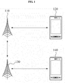
- FIG. 1 is a view for describing a reference signal (RS) transmission system according to an embodiment of the present invention.
- the RS transmission system includes a base station 110, a relay 130, a macro terminal 120, and a relay terminal 140.
- the macro terminal 120 receives data directly from the base station 110 by connecting directly with the base station 110.
- the relay terminal 140 connects with the relay 130 and receives data from the relay 130.
- the relay 130 receives data from the base station 110 and forwards the received data to the relay terminal 140.
- the RS transmission system also includes an uplink and a downlink between the base station 110 and the terminal 120, an uplink and a downlink between the base station 110 and the relay 130, and an uplink and a downlink between the relay 130 and the relay terminal 140.
- the six links need to efficiently allocate and use limited system resources.
- FIG. 2 is a view showing a multicast broadcast single frequency network (MBSFN) sub frame according to an embodiment of the present invention.
- MMSFN multicast broadcast single frequency network
- the relay 130 informs, by a signal, terminals that a sub frame used for reception of a signal from the base station 110 is the MBSFN sub frame.
- each of frames 210 may include ten sub frames.
- the relay 130 may designate first frames and sixth frames 220, 230, 240, and 250 of the frames 210 as the MBSFN sub frames.
- the relay 130 may receive data from the base station 110 using the MBSFN sub frames 220, 230, 240, and 250 and forward data to the relay terminal 140 using sub frames other than the MBSFN sub frames 220, 230, 240, and 250.
- FIG. 3 is a view showing the structure of the MBSFN sub frame according to the embodiment.
- a sub frame 300 signaled as the MBSFN sub frame to receive data from the base station may transmit control signals using part of symbols 310 located at a front portion of the sub frame 300.
- the control signals may include an RS, a physical control format indicator channel (PCFICH), a physical downlink control channel (PDCCH), and a Physical H-ARQ Indicator Channel (PHICH).
- the relay receives signals from the base station using the other slots of the sub frame 300.
- FIG. 4 shows the structures of the sub frames of the base station and of the relay in a case where the relay receives data transmitted by the base station.
- Part (a) of FIG. 4 shows the structure of a downlink sub frame 410 transmitted by the base station 110 to the macro terminal 120 and the relay 130.
- the sub frame 410 includes a control signal region 420 and data regions 430.
- the base station 110 may transmit the RS, the PCFICH, the PDCCH, and the PHICH using the control signal region 420 and transmit a physical downlink shared channel (PDSCH) using the data region 430.
- the control signal region 420 may consist of the symbols of the front part of the sub frame as shown in FIG. 3 .
- Part (b) of FIG. 4 shows the structure of a downlink sub frame 440 transmitted by the relay 130 to the relay terminal 140.
- the relay 130 provides a signal that the downlink sub frame 440 corresponding to the sub frame 410 of the base station 110 is the MBSFN sub frame.
- the downlink sub frame 440 set to receive a signal from the base station includes a control signal region 450 and a reception region 460.
- the relay 130 may transmit the RS, the PCFICH, the PDCCH, and the PHICH using the control signal region 450 for the relay 140 that receives data from the relay 130.
- the relay 130 receives data from the base station 110 but does not transmit data to the relay terminal 140 for a time corresponding to the reception region 460.
- FIG. 5 shows sub frames containing a CSI RS according to an embodiment of the present invention.
- the CSI RS may not be contained in all sub frames. In other words, only some of the sub frames transmitted by the base station 110 to the macro terminal 120 or the relay 130 may include the CSI RS.
- the macro terminal 120 or the relay 130 receives the CSI RS and estimates a state of channel between the base station 110 and the macro terminal 120 or between the base station 110 and the relay 130 using the CSI RS.
- the macro terminal 120 and the relay 130 need to be aware of which sub frame contains the CSI RS. That is, the macro terminal 120 and the relay 130 need to be aware of a transmission pattern of the CSI RS.
- the base station 110 informs the macro terminal 120 and the relay 130 of the transmission pattern of the CSI RS by signals. Therefore, the macro terminal 120 and the relay 130 may receive the CSI RS from the base station 110 based on the transmission pattern.
- the base station 110 may periodically transmit the CSI RS.
- all the base stations may have the same CSI RS transmission period. All the base stations may transmit the CSI RS using different sub frames and using cell specific offsets while transmitting the CSI RS by the same transmission period.
- the CSI RS pattern information may include the CSI RS transmission period and offset.
- the sub frame number may represent an order of a plurality of sub frames of a frame.
- the base station A may transmit the CSI RS only in a sub frame satisfying [Expression 1] below, wherein N denotes the number of sub frames included in one frame and ⁇ denotes the CSI RS transmission period.
- ⁇ a n f * N + n s mod ⁇
- all the base stations may have the same or different offsets ⁇ .
- the offset ⁇ and the CSI RS transmission period ⁇ may vary over time.
- the base station may transmit the offset ⁇ to the macro terminal 120 and the relay 130.
- the macro terminal 120 and the relay 130 may receive the CSI RS based on the offset ⁇ and the CSI RS transmission period ⁇ .
- Part (a) of FIG. 5 illustrates transmission of the CSI RS using the sub frames in a case where the offset ⁇ is '0' and the CSI RS transmission period ⁇ is '5'.
- the base station 110 transmits the CSI RS to the sub frames belonging to the set of [Expression 2].
- the transmission period corresponding to each element of the offset vector is '5'.
- the transmission period corresponding to each element of the offset vector may be different. That is, the base station 110 may transmit the CSI RS to sub frames belonging to a union U of [Expression 3] below with respect to a period vector ( ⁇ 1 , ⁇ 2 , ⁇ 3 ,..., ⁇ N ) and an offset vector ( ⁇ 1 , ⁇ 2 , ⁇ 3 ,..., ⁇ N ). In this case, the base station 110 may generate the CSI RS pattern information including at least one period and at least one offset and inform the macro terminal 120 and the relay 130 of the CSI RS pattern information by signals.
- Hatched sub frames 531, 532, 533, 534, 535, 536, 537, 538, and 539 contain the CSI RS.
- the period vector or the offset vector with respect to a plurality of the base stations may be equal or different.
- the base station 110 may transmit a signal regarding the CSI RS transmission period ⁇ or the offset ⁇ of the CSI RS to the macro terminal 120 or the relay 130 using a control channel (CCH).
- CCH control channel
- the base station 110 may transmit those parameters to the macro terminal 120 and the relay 130 periodically or only when the parameters are changed.
- the system may be set so that the CSI RS is not transmitted to certain predetermined sub frames. For example, if the sub frames satisfy conditions disclosed below, the CSI RS may be not transmitted to the predetermined sub frames even when the predetermined sub frames correspond to the period for transmitting the CSI RS.
- position information of the sub frames which are set to be not transmitted with the CSI RS may be transmitted to the macro terminal 120 and the relay 130 regardless of the period.
- the base station 110 may inform the macro terminal 120 and the relay 130 of the MBSFN sub frames used by the MBMS service.
- the base station 110 may inform the macro terminal 120 and the relay 130 of the downlink sub frames used as the backhaul link for data reception.
- the CSI RS may be used for data transmission and reception between the base station 110 and the relay 130.
- the relay 130 may receive only specific sub frames allocated for a link between the base station 110 and the relay 130. Therefore, if there is no CSI RS in the sub frame allocated for the link between the base station 110 and the relay 130, the relay 130 receives no CSI RS. Accordingly, the base station 110 is limited in determining the sub frame to transmit the CSI RS.
- the base station 110 may not be able to periodically allocate the sub frame to transmit the CSI RS.
- the sub frame to transmit the CSI RS may be determined and a position of the determined sub frame may be transmitted to the macro terminal 120 or the relay 130 using bitmap information. That is, the base station 110 transmits the information on the sub frame containing the CSI RS in the form of the bitmap to the macro terminal 120 or the relay 130.
- the bitmap information may represent whether each of the sub frames contains the CSI RS.
- the sub frame corresponding to the bitmap information contains the CSI RS when a value of the bitmap information is '1' and does not contain the CSI RS when a value of the bitmap information is '0.
- the CSI RS pattern information may contain the bitmap information representing whether the CSI RS is transmitted.
- the base station 110 may transmit an identifier list of the sub frame to transmit the CSI RS to the macro terminal 120 or the relay 130.
- the base station 110 may transmit information on whether an (n+k)-th sub frame contains the CSI RS to the macro terminal 120 and the relay 130 using an n-th sub frame.
- a value 'k' may be equal to or greater than '0' and be varied based on the base stations.
- the base station 110 may transmit the information on whether the (n+k)-th sub frame contains the CSI RS to the macro terminal 120 using a PCFICH channel of the n-th sub frame.
- the base station 110 may transmit the information on whether the (n+k)-th sub frame contains the CSI RS to the relay 130 using a dedicated channel for the relay 130.
- the dedicated channel may be located next to a symbol used for PDCCH transmission and for a transition gap.
- the base station 110 may transmit the n-th sub frame including the value 'k.' That is, the base station 110 informs the macro terminal 120 or the relay 130 that the CSI RS is transmitted to the (n+k)-th sub frame.
- the base station 110 may transmit the CSI RS pattern information to the relay 130 using the dedicated channel for the relay 130.
- the dedicated channel may be a CCH relay or a downlink shared channel for the relay 130.
- the base station 110 transmits the CSI RS only in a part of the sub frames.
- the relay 130 may estimate the CSI RS only in a part of the sub frames. Therefore, the relay 130 is able to receive the CSI RS only when the sub frame where the base station 110 transmits the CSI RS corresponds to the sub frame where the relay 130 receives the signal of the base station 110.
- the relay 130 is not able to receive the CSI RS when those sub frames do not correspond to each other.
- FIG. 6 shows the CSI RS located in a frequency range, according to an embodiment of the present invention.
- the base station 110 transmits the CSI RS to the sub frame allocated to the link between the base station 110 and the relay 130.
- the base station may be contained in all the sub frames allocated to the link between the base station 110 and the relay 130 or part of the sub frames.
- FIG. 6 shows the embodiment where CSI RSs 661, 662, 663, 664, 665, 666, and 667 are present in all frequency ranges 630, 640, and 650 of a sub frame 610.
- FIG. 7 shows the CSI RS present in a frequency range, according to another embodiment.
- CSI RSs 751, 751, and 753 are present in only a frequency range 740 allocated to the relay 130 but not in other frequency ranges 720 and 730.
- the base station 110 may transmit the CSI RS to a plurality of relays.
- a frequency range may be individually allocated to each of the relays.
- the base station 110 may allocate the CSI RS to a union of all the frequency ranges respectively allocated for data transmission to the relays.
- the base station 110 may allocate the CSI RS not only to the union of the all frequency ranges allocated for data transmission to the relays but also to the frequency range allocated for data transmission to the macro terminal.
- FIG. 8 shows the CSI RS present in a frequency range, according to still another embodiment.
- the base station 110 may allocate the CSI RS only to part of frequency ranges of a downlink resource.
- different frequency ranges instead of all the same frequency range may be used in the all sub frames transmitting the CSI RS.
- the base station 110 may inform the relay 130 of which frequency range has the CSI RS.
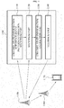
- FIG. 9 is a block diagram showing the structure of a base station according to an embodiment of the present invention.
- the base station 900 includes a CSI RS pattern information transmission unit 910 and a transmission unit 920.
- the CSI RS pattern information transmission unit 910 transmits, to a macro terminal 930 or a relay 940, information on a sub frame containing the CSI RS among all the sub frames transmitted by the transmission unit 920.
- the macro terminal 930 receives data directly from the base station 900 by connecting with the base station 900.
- the macro terminal 930 extracts CSI between the base station 900 and the macro terminal 930 and feeds back the extracted CSI to the base station 900.
- the CSI RS pattern information may include at least one of an identifier list of the sub frame containing the CSI RS, the transmission period and offset of the sub frame containing the CSI RS, a bitmap with respect to the sub frame containing the CSI RS, and information on whether the CSI RS is present in a sub frame after a k-th sub frame.
- the CSI RS pattern information may include position information on the sub frames set not to transmit the CSI RS regardless of a period.
- the CSI RS pattern information may include the position information of the MBSFN sub frame set for the MBMS service.
- the CSI RS pattern information may include position information of the downlink sub frame set for the data reception backhaul link.
- the CSI RS pattern information or the information on the sub frame containing the CSI RS may be set to be the same or different with respect to a plurality of base stations.
- the CSI RS pattern information transmission unit 910 may transmit the information on the sub frame containing the CSI RS to the macro terminal 930 through the CCH.
- the CSI RS pattern information transmission unit 910 may transmit the information on the sub frame containing the CSI RS to the relay 940.
- the transmission unit 920 transmits the CSI RS and data to the macro terminal 930 or the relay 940 with reference to the information on the sub frame.
- the transmission unit 920 may not transmit the CSI RS in the MBSFN sub frame set for the MBMS service.
- the transmission unit 920 may not transmit the CSI RS in the downlink sub frame used for the data reception backhaul link.
- the relay 940 extracts the CSI with respect to the base station 900 using the CSI RS.
- FIG 10 is a block diagram showing the structure of a relay according to an embodiment of the present invention.
- the relay 1000 includes a CSI RS pattern information reception unit 1010, a reception unit 1020, a CSI extraction unit 1030, and a feedback unit 1040.
- a base station 1050 transmits the sub frame containing data to the information 1000.
- Part of the sub frames transmitted by the base station 1050 may contain the CSI RS.
- the CSI RS pattern information reception unit 1010 receives the information on the sub frame containing the CSI RS from the base station 1050.
- the CSI RS pattern information may include at least one of an identifier list of the sub frame containing the CSI RS, the transmission period and offset of the sub frame containing the CSI RS, a bitmap with respect to the sub frame containing the CSI RS, and information on whether the CSI RS is present in a sub frame after a k-th sub frame.
- the CSI RS pattern information may include position information on the sub frames set not to transmit the CSI RS regardless of a period.
- the CSI RS pattern information may include the position information of the MBSFN sub frame set for the MBMS service.
- the CSI RS pattern information may include position information of the downlink sub frame set for the data reception backhaul link.
- the reception unit 1020 receives the CSI RS from the base station 1050 using the information on sub frame.
- the CSI extraction unit 1030 extracts the CSI between the base station 1050 and the relay 1000 using the CSI RS.
- the feedback unit 1040 may feed back the extracted CSI to the base station 1050.
- the base station 1050 may transmit data directly to a macro terminal 1060 connected with the base station 1050.
- FIG. 11 is a block diagram showing the structure of a terminal according to an embodiment of the present invention.
- the terminal 1100 includes a CSI RS pattern information reception unit 1110, a reception unit 1120, a CSI extraction unit 1130, and a feedback unit 1140.
- the CSI RS pattern information reception unit 1110 receives the information on the sub frame containing the CSI RS from the base station 1150.
- the CSI RS pattern information may include at least one of an identifier list of the sub frame containing the CSI RS, the transmission period and offset of the sub frame containing the CSI RS, a bitmap with respect to the sub frame containing the CSI RS, and information on whether the CSI RS is present in a sub frame after a k-th sub frame.
- the CSI RS pattern information may include position information on the sub frames set not to transmit the CSI RS regardless of a period.
- the CSI RS pattern information may include the position information of the MBSFN sub frame set for the MBMS service.
- the CSI RS pattern information may include position information of the downlink sub frame set for the data reception backhaul link.
- the CSI RS pattern information reception unit 1110 may receive the information on the sub frame through the CCH.
- the reception unit 1120 receives the CSI RS from the base station 1150 using the information on sub frame.
- the CSI extraction unit 1130 extracts the CSI between the base station 1050 and the relay 1100 using the CSI RS.
- the feedback unit 1140 may feed back the extracted CSI to the base station 1150.
- the base station 1150 may transmit data directly to a macro terminal 1160 connected with the base station 1150.
- the relay 1160 may forward the data received from the base station 1150 to a relay terminal 1170 connected with the relay 1160.
Landscapes
- Engineering & Computer Science (AREA)
- Signal Processing (AREA)
- Computer Networks & Wireless Communication (AREA)
- Mobile Radio Communication Systems (AREA)
Abstract
Description
- The present invention relates to a reference signal (RS) necessary for data transmission and reception and to signaling of the RS, and more particularly, to an RS signal for data transmission and reception between a base station and a relay in a wireless communication system using the relay and signaling of the RS.
- An appropriate reference signal (RS) needs to be transmitted for efficient transmission and reception of data. The RS is necessary for modulation of data and also for generation of channel state information (CSI) through estimation of a channel state between a base station and a terminal. The terminal generates CSI and transmits the CSI to the base station. The base station transmits data to the terminal based on the CSI. An RS used to extract the CSI may be referred to as a 'CSI RS.'
- A plurality of RSs are necessary in general for multiple input multiple output (MIMO) transmission and reception. Exemplarily, the RSs transmitted by the base station are orthogonal to one another. The base station transmits its own specific RS to all terminals in the coverage. In general, as the number of antennas installed in the base station increases, more RSs are necessary.
- An aspect of the present invention provides a method to transmit a channel state information (CSI) reference signal (RS) for data transmission between a base station and a relay in a system which uses the relay.
- According to an aspect of the present invention, there is provided a base station which transmits sub frames to a terminal and a relay, including a channel state information (CSI) reference signal (RS) pattern information transmission unit to transmit information on a sub frame which contains a CSI RS among the sub frames to the terminal or the relay; and a transmission unit to transmit the CSI RS and data to the terminal or the relay with reference to the information on the sub frame.
- According to an aspect of the present invention, there is provided a relay including a CSI RS pattern information reception unit to receive, from a base station, information on a sub frame which contains a CSI RS; a reception unit to receive the CSI RS from the base station with reference to the information on the sub frame; a CSI extraction unit to extract CSI between the base station and the relay using the CSI RS; and a feedback unit to transmit the extracted CSI to the base station.
- According to an aspect of the present invention, there is provided a terminal including a CSI RS pattern information reception unit to receive, from a base station, information on a sub frame which contains a CSI RS; a reception unit to receive the CSI RS from the base station with reference to the information on the sub frame; a CSI extraction unit to extract CSI between the base station and the relay using the CSI RS; and a feedback unit to transmit the extracted CSI to the base station.
- According to the embodiments of the present invention, the CSI RS for data transmission between the base station and the relay in a system using a relay may be efficiently transmitted.
-
-
FIG 1 is a view for describing a reference signal (RS) transmission system; -
FIG 2 is a view showing a multicast broadcast single frequency network (MBSFN) sub frame according to an embodiment of the present invention; -
FIG 3 is a view showing the structure of the MBSFN sub frame according to the embodiment; -
FIG 4 is a view showing the structures of sub frames of a base station and a relay in a case where the relay receives data transmitted by the base station; -
FIG. 5 is a view showing sub frames containing an RS according to an embodiment of the present invention; -
FIG. 6 is a view showing an RS located in a frequency range according to an embodiment; -
FIG 7 is a view showing an RS located in a frequency range according to another embodiment; -
FIG. 8 is a view showing an RS located in a frequency range according to still another embodiment; -
FIG 9 is a block diagram showing the structure of the base station according to an embodiment of the present invention; -
FIG. 10 is a block diagram showing the structure of the relay according to an embodiment of the present invention; and -
FIG. 11 is a block diagram showing the structure of a terminal according to an embodiment of the present invention. - Reference will now be made in detail to embodiments of the present invention, examples of which are illustrated in the accompanying drawings, wherein like reference numerals refer to the like elements throughout. The embodiments are described below in order to explain the present invention by referring to the figures.
-
FIG. 1 is a view for describing a reference signal (RS) transmission system according to an embodiment of the present invention. - The RS transmission system includes a
base station 110, arelay 130, amacro terminal 120, and arelay terminal 140. Themacro terminal 120 receives data directly from thebase station 110 by connecting directly with thebase station 110. Therelay terminal 140 connects with therelay 130 and receives data from therelay 130. Therelay 130 receives data from thebase station 110 and forwards the received data to therelay terminal 140. - The RS transmission system also includes an uplink and a downlink between the
base station 110 and theterminal 120, an uplink and a downlink between thebase station 110 and therelay 130, and an uplink and a downlink between therelay 130 and therelay terminal 140. In the RS transmission system, the six links need to efficiently allocate and use limited system resources. -
FIG. 2 is a view showing a multicast broadcast single frequency network (MBSFN) sub frame according to an embodiment of the present invention. - The
relay 130 informs, by a signal, terminals that a sub frame used for reception of a signal from thebase station 110 is the MBSFN sub frame. - As shown in
FIG. 2 , each offrames 210 may include ten sub frames. Therelay 130 may designate first frames andsixth frames frames 210 as the MBSFN sub frames. Therelay 130 may receive data from thebase station 110 using the MBSFNsub frames relay terminal 140 using sub frames other than the MBSFNsub frames -
FIG. 3 is a view showing the structure of the MBSFN sub frame according to the embodiment. - In
FIG. 3 , a horizontal axis denotes an elapse of time while a vertical axis denotes a frequency range. Asub frame 300 signaled as the MBSFN sub frame to receive data from the base station may transmit control signals using part ofsymbols 310 located at a front portion of thesub frame 300. Here, the control signals may include an RS, a physical control format indicator channel (PCFICH), a physical downlink control channel (PDCCH), and a Physical H-ARQ Indicator Channel (PHICH). The relay receives signals from the base station using the other slots of thesub frame 300. -
FIG. 4 shows the structures of the sub frames of the base station and of the relay in a case where the relay receives data transmitted by the base station. - Part (a) of
FIG. 4 shows the structure of adownlink sub frame 410 transmitted by thebase station 110 to themacro terminal 120 and therelay 130. - The
sub frame 410 includes acontrol signal region 420 anddata regions 430. Thebase station 110 may transmit the RS, the PCFICH, the PDCCH, and the PHICH using thecontrol signal region 420 and transmit a physical downlink shared channel (PDSCH) using thedata region 430. Thecontrol signal region 420 may consist of the symbols of the front part of the sub frame as shown inFIG. 3 . - Part (b) of
FIG. 4 shows the structure of adownlink sub frame 440 transmitted by therelay 130 to therelay terminal 140. Therelay 130 provides a signal that thedownlink sub frame 440 corresponding to thesub frame 410 of thebase station 110 is the MBSFN sub frame. Thedownlink sub frame 440 set to receive a signal from the base station includes acontrol signal region 450 and areception region 460. Therelay 130 may transmit the RS, the PCFICH, the PDCCH, and the PHICH using thecontrol signal region 450 for therelay 140 that receives data from therelay 130. Therelay 130 receives data from thebase station 110 but does not transmit data to therelay terminal 140 for a time corresponding to thereception region 460. -
FIG. 5 shows sub frames containing a CSI RS according to an embodiment of the present invention. - The CSI RS may not be contained in all sub frames. In other words, only some of the sub frames transmitted by the
base station 110 to themacro terminal 120 or therelay 130 may include the CSI RS. Themacro terminal 120 or therelay 130 receives the CSI RS and estimates a state of channel between thebase station 110 and themacro terminal 120 or between thebase station 110 and therelay 130 using the CSI RS. - Since not all the sub frames contain the CSI RS, the
macro terminal 120 and therelay 130 need to be aware of which sub frame contains the CSI RS. That is, themacro terminal 120 and therelay 130 need to be aware of a transmission pattern of the CSI RS. - The
base station 110 informs themacro terminal 120 and therelay 130 of the transmission pattern of the CSI RS by signals. Therefore, themacro terminal 120 and therelay 130 may receive the CSI RS from thebase station 110 based on the transmission pattern. - According to an embodiment, the
base station 110 may periodically transmit the CSI RS. For example, all the base stations may have the same CSI RS transmission period. All the base stations may transmit the CSI RS using different sub frames and using cell specific offsets while transmitting the CSI RS by the same transmission period. In this case, the CSI RS pattern information may include the CSI RS transmission period and offset. - Presuming that θa denotes an offset of a base station A and nf and ns denote a frame number and a sub frame number, respectively, the sub frame number may represent an order of a plurality of sub frames of a frame. The base station A may transmit the CSI RS only in a sub frame satisfying [Expression 1] below, wherein N denotes the number of sub frames included in one frame and Δ denotes the CSI RS transmission period.

- According to an embodiment, all the base stations may have the same or different offsets θ. The offset θ and the CSI RS transmission period Δ may vary over time. The base station may transmit the offset θ to the
macro terminal 120 and therelay 130. Themacro terminal 120 and therelay 130 may receive the CSI RS based on the offset θ and the CSI RS transmission period Δ. - Part (a) of
FIG. 5 illustrates transmission of the CSI RS using the sub frames in a case where the offset θ is '0' and the CSI RS transmission period Δ is '5'. Sub frames 511, 512, 513, 514, and 515, hatched in the drawing, contain the CSI RS. - According to an embodiment, the
base station 110 may transmit the CSI RS using a set of one or more uniform-spaced sub frames. For example, presuming that S(Δ,θ) denotes a set of the uniform-spaced sub frames of which the transmission period is denoted by Δ and the offset is denoted by θ, thebase station 110 may transmit the CSI RS using the sub frames belonging to a union U of [Expression 2] below. In this case, thebase station 110 informs themacro terminal 120 and therelay 130 of the CSI RS pattern information including one or more offsets. In other words, the CSI RS pattern information includes (θ 1,θ 2,θ 3,...,θN ).
- When there is an offset vector (θ 1,θ 2,θ 3,...,θN ), the
base station 110 transmits the CSI RS to the sub frames belonging to the set of [Expression 2]. - Part (b) of
FIG. 5 shows transmission of the CSI RS when an offset vector {θ 1 = 0, θ 2 = 2} is provided. The transmission period corresponding to each element of the offset vector is '5'. Sub frames 521, 522, 523, 524, 525, 526, 527, 528, and 529, hatched in the drawing, contain the CSI RS. - According to an embodiment, the transmission period corresponding to each element of the offset vector may be different. That is, the
base station 110 may transmit the CSI RS to sub frames belonging to a union U of [Expression 3] below with respect to a period vector (Δ1,Δ2,Δ3,...,Δ N ) and an offset vector (θ 1 ,θ 2 ,θ 3 ,...,θN ). In this case, thebase station 110 may generate the CSI RS pattern information including at least one period and at least one offset and inform themacro terminal 120 and therelay 130 of the CSI RS pattern information by signals.
- Part (c) of
FIG 5 shows transmission of the CSI RS in a case where a period vector is {5,4} and an offset vector is {θ 1 = 0, θ 2 = 3}. Hatched sub frames 531, 532, 533, 534, 535, 536, 537, 538, and 539 contain the CSI RS. - According to an embodiment, the period vector or the offset vector with respect to a plurality of the base stations may be equal or different.
- According to an embodiment, the
base station 110 may transmit a signal regarding the CSI RS transmission period Δ or the offset θ of the CSI RS to themacro terminal 120 or therelay 130 using a control channel (CCH). - According to an embodiment, the
base station 110 may transmit those parameters to themacro terminal 120 and therelay 130 periodically or only when the parameters are changed. - According to an embodiment, in the case where the CSI RS is periodically transmitted, the system may be set so that the CSI RS is not transmitted to certain predetermined sub frames. For example, if the sub frames satisfy conditions disclosed below, the CSI RS may be not transmitted to the predetermined sub frames even when the predetermined sub frames correspond to the period for transmitting the CSI RS.
- 1) MBSFN sub frames designated for a multimedia broadcast multicast service (MBMS) service
- 2) downlink sub frames used as a backhaul link for data reception
- According to an embodiment, position information of the sub frames which are set to be not transmitted with the CSI RS may be transmitted to the
macro terminal 120 and therelay 130 regardless of the period. - According to an embodiment, the
base station 110 may inform themacro terminal 120 and therelay 130 of the MBSFN sub frames used by the MBMS service. - According to an embodiment, the
base station 110 may inform themacro terminal 120 and therelay 130 of the downlink sub frames used as the backhaul link for data reception. - The CSI RS may be used for data transmission and reception between the
base station 110 and therelay 130. Among the sub frames transmitted by thebase station 110, therelay 130 may receive only specific sub frames allocated for a link between thebase station 110 and therelay 130. Therefore, if there is no CSI RS in the sub frame allocated for the link between thebase station 110 and therelay 130, therelay 130 receives no CSI RS. Accordingly, thebase station 110 is limited in determining the sub frame to transmit the CSI RS. - According to an embodiment, the
base station 110 may not be able to periodically allocate the sub frame to transmit the CSI RS. In this case, the sub frame to transmit the CSI RS may be determined and a position of the determined sub frame may be transmitted to themacro terminal 120 or therelay 130 using bitmap information. That is, thebase station 110 transmits the information on the sub frame containing the CSI RS in the form of the bitmap to themacro terminal 120 or therelay 130. The bitmap information may represent whether each of the sub frames contains the CSI RS. For example, it may be considered that the sub frame corresponding to the bitmap information contains the CSI RS when a value of the bitmap information is '1' and does not contain the CSI RS when a value of the bitmap information is '0.' Here, the CSI RS pattern information may contain the bitmap information representing whether the CSI RS is transmitted. - According to an embodiment, the
base station 110 may transmit an identifier list of the sub frame to transmit the CSI RS to themacro terminal 120 or therelay 130. - According to an embodiment, the
base station 110 may transmit information on whether an (n+k)-th sub frame contains the CSI RS to themacro terminal 120 and therelay 130 using an n-th sub frame. Here, a value 'k' may be equal to or greater than '0' and be varied based on the base stations. - For example, the
base station 110 may transmit the information on whether the (n+k)-th sub frame contains the CSI RS to themacro terminal 120 using a PCFICH channel of the n-th sub frame. - Since the
relay 130 is not able to receive the PCFICH channel, thebase station 110 may transmit the information on whether the (n+k)-th sub frame contains the CSI RS to therelay 130 using a dedicated channel for therelay 130. According to an embodiment, the dedicated channel may be located next to a symbol used for PDCCH transmission and for a transition gap. - According to an embodiment, the
base station 110 may transmit the n-th sub frame including the value 'k.' That is, thebase station 110 informs themacro terminal 120 or therelay 130 that the CSI RS is transmitted to the (n+k)-th sub frame. - Since the
relay 130 is capable of receiving only part of the sub frames transmitted by thebase station 110, therelay 130 is not able to receive the CSI RS pattern information being transmitted by thebase station 110 to themacro terminal 120. Thebase station 110 may transmit the CSI RS pattern information to therelay 130 using the dedicated channel for therelay 130. The dedicated channel may be a CCH relay or a downlink shared channel for therelay 130. - The
base station 110 transmits the CSI RS only in a part of the sub frames. Therelay 130 may estimate the CSI RS only in a part of the sub frames. Therefore, therelay 130 is able to receive the CSI RS only when the sub frame where thebase station 110 transmits the CSI RS corresponds to the sub frame where therelay 130 receives the signal of thebase station 110. Therelay 130 is not able to receive the CSI RS when those sub frames do not correspond to each other. -
FIG. 6 shows the CSI RS located in a frequency range, according to an embodiment of the present invention. Thebase station 110 transmits the CSI RS to the sub frame allocated to the link between thebase station 110 and therelay 130. The base station may be contained in all the sub frames allocated to the link between thebase station 110 and therelay 130 or part of the sub frames. -
FIG. 6 shows the embodiment whereCSI RSs sub frame 610. -
FIG. 7 shows the CSI RS present in a frequency range, according to another embodiment. According to the embodiment shown inFIG. 7 ,CSI RSs frequency range 740 allocated to therelay 130 but not in other frequency ranges 720 and 730. - According to an embodiment, the
base station 110 may transmit the CSI RS to a plurality of relays. In this case, a frequency range may be individually allocated to each of the relays. Thebase station 110 may allocate the CSI RS to a union of all the frequency ranges respectively allocated for data transmission to the relays. - According to an embodiment, the
base station 110 may allocate the CSI RS not only to the union of the all frequency ranges allocated for data transmission to the relays but also to the frequency range allocated for data transmission to the macro terminal. -
FIG. 8 shows the CSI RS present in a frequency range, according to still another embodiment. In the embodiment shown inFIG. 8 , thebase station 110 may allocate the CSI RS only to part of frequency ranges of a downlink resource. In this case, different frequency ranges instead of all the same frequency range may be used in the all sub frames transmitting the CSI RS. In this case, thebase station 110 may inform therelay 130 of which frequency range has the CSI RS. -
FIG. 9 is a block diagram showing the structure of a base station according to an embodiment of the present invention. - The
base station 900 includes a CSI RS patterninformation transmission unit 910 and atransmission unit 920. - The CSI RS pattern
information transmission unit 910 transmits, to amacro terminal 930 or arelay 940, information on a sub frame containing the CSI RS among all the sub frames transmitted by thetransmission unit 920. Themacro terminal 930 receives data directly from thebase station 900 by connecting with thebase station 900. - According to an embodiment, the
macro terminal 930 extracts CSI between thebase station 900 and themacro terminal 930 and feeds back the extracted CSI to thebase station 900. - According to an embodiment, the CSI RS pattern information may include at least one of an identifier list of the sub frame containing the CSI RS, the transmission period and offset of the sub frame containing the CSI RS, a bitmap with respect to the sub frame containing the CSI RS, and information on whether the CSI RS is present in a sub frame after a k-th sub frame.
- According to an embodiment, the CSI RS pattern information may include position information on the sub frames set not to transmit the CSI RS regardless of a period.
- According to an embodiment, the CSI RS pattern information may include the position information of the MBSFN sub frame set for the MBMS service.
- According to an embodiment, the CSI RS pattern information may include position information of the downlink sub frame set for the data reception backhaul link.
- According to an embodiment, the CSI RS pattern information or the information on the sub frame containing the CSI RS may be set to be the same or different with respect to a plurality of base stations.
- According to an embodiment, the CSI RS pattern
information transmission unit 910 may transmit the information on the sub frame containing the CSI RS to themacro terminal 930 through the CCH. - According to an embodiment, the CSI RS pattern
information transmission unit 910 may transmit the information on the sub frame containing the CSI RS to therelay 940. - The
transmission unit 920 transmits the CSI RS and data to themacro terminal 930 or therelay 940 with reference to the information on the sub frame. Thetransmission unit 920 may not transmit the CSI RS in the MBSFN sub frame set for the MBMS service. - The
transmission unit 920 may not transmit the CSI RS in the downlink sub frame used for the data reception backhaul link. - The
relay 940 extracts the CSI with respect to thebase station 900 using the CSI RS. -
FIG 10 is a block diagram showing the structure of a relay according to an embodiment of the present invention. - The
relay 1000 includes a CSI RS patterninformation reception unit 1010, areception unit 1020, aCSI extraction unit 1030, and afeedback unit 1040. - A
base station 1050 transmits the sub frame containing data to theinformation 1000. Part of the sub frames transmitted by thebase station 1050 may contain the CSI RS. - The CSI RS pattern
information reception unit 1010 receives the information on the sub frame containing the CSI RS from thebase station 1050. - According to an embodiment, the CSI RS pattern information may include at least one of an identifier list of the sub frame containing the CSI RS, the transmission period and offset of the sub frame containing the CSI RS, a bitmap with respect to the sub frame containing the CSI RS, and information on whether the CSI RS is present in a sub frame after a k-th sub frame.
- According to an embodiment, the CSI RS pattern information may include position information on the sub frames set not to transmit the CSI RS regardless of a period.
- According to an embodiment, the CSI RS pattern information may include the position information of the MBSFN sub frame set for the MBMS service.
- According to an embodiment, the CSI RS pattern information may include position information of the downlink sub frame set for the data reception backhaul link.
- The
reception unit 1020 receives the CSI RS from thebase station 1050 using the information on sub frame. - The
CSI extraction unit 1030 extracts the CSI between thebase station 1050 and therelay 1000 using the CSI RS. - The
feedback unit 1040 may feed back the extracted CSI to thebase station 1050. - The
base station 1050 may transmit data directly to amacro terminal 1060 connected with thebase station 1050. -
FIG. 11 is a block diagram showing the structure of a terminal according to an embodiment of the present invention. - The terminal 1100 includes a CSI RS pattern
information reception unit 1110, areception unit 1120, aCSI extraction unit 1130, and afeedback unit 1140. - The CSI RS pattern
information reception unit 1110 receives the information on the sub frame containing the CSI RS from thebase station 1150. - According to an embodiment, the CSI RS pattern information may include at least one of an identifier list of the sub frame containing the CSI RS, the transmission period and offset of the sub frame containing the CSI RS, a bitmap with respect to the sub frame containing the CSI RS, and information on whether the CSI RS is present in a sub frame after a k-th sub frame.
- According to an embodiment, the CSI RS pattern information may include position information on the sub frames set not to transmit the CSI RS regardless of a period.
- According to an embodiment, the CSI RS pattern information may include the position information of the MBSFN sub frame set for the MBMS service.
- According to an embodiment, the CSI RS pattern information may include position information of the downlink sub frame set for the data reception backhaul link.
- According to an embodiment, the CSI RS pattern
information reception unit 1110 may receive the information on the sub frame through the CCH. - The
reception unit 1120 receives the CSI RS from thebase station 1150 using the information on sub frame. - The
CSI extraction unit 1130 extracts the CSI between thebase station 1050 and therelay 1100 using the CSI RS. - The
feedback unit 1140 may feed back the extracted CSI to thebase station 1150. - The
base station 1150 may transmit data directly to amacro terminal 1160 connected with thebase station 1150. Therelay 1160 may forward the data received from thebase station 1150 to arelay terminal 1170 connected with therelay 1160. - Although a few embodiments of the present invention have been shown and described, the present invention is not limited to the described embodiments. Instead, it would be appreciated by those skilled in the art that changes may be made to these embodiments without departing from the principles and spirit of the invention, the scope of which is defined by the claims and their equivalents.
- Moreover, the present invention is disclosed in the following examples:
- 1. A base station which transmits sub frames to a terminal and a relay, comprising:
- a channel state information (CSI) reference signal (RS) pattern information transmission unit to transmit information on a sub frame which contains a CSI RS among the sub frames to the terminal or the relay; and
- a transmission unit to transmit the CSI RS and data to the terminal or the relay with reference to the information on the sub frame.
- 2. The base station of example 1, wherein the CSI RS pattern information transmission unit transmits the information on the sub frame containing the CSI RS, the information comprising either a period or an offset of a sub frame for transmission of the CSI RS.
- 3. The base station of example 2, wherein the CSI RS pattern information transmission unit sets the period or the offset of the sub frame transmitting the CSI RS to be different from either a period or an offset of a sub frame of another cell.
- 4. The base station of example 1, wherein the CSI RS pattern information transmission unit sets the information on the sub frame to be different from information on a sub frame of another cell.
- 5. The base station of example 1, wherein the information on the sub frame comprises at least one period or at least one offset of the sub frame.
- 6. The base station of example 1, wherein the information on the sub frame comprises information on sub frames set to prevent transmission of the CSI RS
- 7. The base station of example 1, wherein the information on the sub frame is used as a backhaul link for reception of data.
- 8. The base station of example 1, wherein the information on the sub frame comprises information of a multicast broadcast single frequency network (MBSFN) sub frame set for a multimedia broadcast multicast service (MBMS) service.
- 9. The base station of example 1, wherein the CSI RS pattern information comprises at least one of an identifier list of the sub frame, a transmission period and an offset of the sub frame, a bitmap regarding the sub frame, and information on whether a CSI RS exists in a k-th sub frame from the sub frame.
- 10. The base station of example 1, wherein the transmission unit does not transmit the CSI RS in a downlink sub frame used as the backhaul link for data reception.
- 11. The base station of example 1, wherein the transmission unit does not transmit the CSI RS in an MBSFN sub frame set for an MBMS service.
- 12. The base station of example 1, wherein the CSI RS pattern information transmission unit transmits a signal containing the information on the sub frame through a dedicated channel receivable by a relay.
- 13. The base station of example 12, wherein the CSI RS pattern information transmission unit transmits a signal containing the information on the sub frame through a control channel for a relay or a downlink shared channel.
- 14. A relay comprising:
- a CSI RS pattern information reception unit to receive, from a base station,
information on a sub frame which contains a CSI RS; - a reception unit to receive the CSI RS from the base station with reference to
the information on the sub frame; - a CSI extraction unit to extract CSI between the base station and the relay
using the CSI RS; and - a feedback unit to transmit the extracted CSI to the base station.
- a CSI RS pattern information reception unit to receive, from a base station,
- 15. A terminal comprising:
- a CSI RS pattern information reception unit to receive from a base station
information on a sub frame which contains a CSI RS; - a reception unit to receive the CSI RS from the base station with reference to
the information on the sub frame; - a CSI extraction unit to extract CSI between the base station and the terminal
using the CSI RS; and - a feedback unit to transmit the extracted CSI to the base station.
- a CSI RS pattern information reception unit to receive from a base station
Claims (14)
- A method for a base station to transmit reference signal, the method comprising:transmitting a pattern information about sub-frames containing CSI (Channel State Information) reference signal among consecutive sub-frames to a terminal or a relay; andtransmitting the CSI reference signal on the sub-frames corresponding to the pattern information to the terminal or the relay.
- The method of claim 1, wherein the pattern information includes information on transmission period and offset of the sub-frames containing the CSI reference signal.
- The method of claim 2, wherein the transmission period or the offset of the sub-frames containing the CSI reference signal is configured identically or differently with transmission period or offset of sub-frames containing CSI reference signals of other cells.
- The method of claim 2, wherein the pattern information includes one or more transmission periods and one or more offsets.
- The method of claim 2, wherein the CSI reference signal is not transmitted in special sub-frames although the special sub-frames correspond to the transmission period and the offset.
- The method of claim 5, wherein the special sub-frames are MBSFN sub-frames designated for a MBMS service or backhaul downlink sub-frames.
- The method of claim 5, further comprising:transmitting position information on the special sub-frames to the terminal or the relay.
- A method for a terminal or a relay to receive reference signal, the method comprising:receiving a pattern information about sub-frames containing CSI (Channel State Information) reference signal among consecutive sub-frames from a base station; andreceiving the CSI reference signal on the sub-frames corresponding to the pattern information from the base station.
- The method of claim 8, wherein the pattern information includes information on transmission period and offset of the sub-frames containing the CSI reference signal.
- The method of claim 9, wherein the pattern information includes one or more transmission periods and one or more offsets.
- The method of claim 9, wherein the CSI reference signal is not received in special sub-frames although the special sub-frames correspond to the transmission period and the offset.
- The method of claim 11, further comprising:receiving position information on the special sub-frames from the base station.
- A method for a base station to transmit reference signal, the method comprising:transmitting an indication information about CSI-RS sub-frames containing Channel State Information reference signal among consecutive sub-frames to a terminal or a relay; andtransmitting the Channel State Information reference signal on the CSI-RS sub-frames corresponding to the indication information to the terminal or the relay;wherein the indication information includes at least one of1) transmission period and offset of the CSI-RS sub-frames,2) an identifier list of the CSI-RS sub-frames,3) an information indicating whether the Channel State Information reference signal exists in a k-th next sub-frame,4) a bitmap information indicating the CSI-RS sub-frames.
- A method for a terminal or a relay to receive reference signal, the method comprising:receiving an indication information about CSI-RS sub-frames containing Channel State Information reference signal among consecutive sub-frames from a base station; andreceiving the Channel State Information reference signal on the CSI-RS sub-frames corresponding to the indication information from the base station;wherein the indication information includes at least one of1) transmission period and offset of the CSI-RS sub-frames,2) an identifier list of the CSI-RS sub-frames,3) an information indicating whether the Channel State Information reference signal exists in a k-th next sub-frame,4) a bitmap information indicating the CSI-RS sub-frames.
Applications Claiming Priority (6)
| Application Number | Priority Date | Filing Date | Title |
|---|---|---|---|
| KR20090023257 | 2009-03-18 | ||
| KR20090024128 | 2009-03-20 | ||
| KR20090024275 | 2009-03-23 | ||
| KR20090094999 | 2009-10-07 | ||
| EP10753717.7A EP2410671B1 (en) | 2009-03-18 | 2010-03-18 | Method for signaling patterns of csi-rs subframes |
| PCT/KR2010/001696 WO2010107267A2 (en) | 2009-03-18 | 2010-03-18 | System for transmitting reference signal with information on state of channel |
Related Parent Applications (2)
| Application Number | Title | Priority Date | Filing Date |
|---|---|---|---|
| EP10753717.7A Division EP2410671B1 (en) | 2009-03-18 | 2010-03-18 | Method for signaling patterns of csi-rs subframes |
| EP10753717.7A Division-Into EP2410671B1 (en) | 2009-03-18 | 2010-03-18 | Method for signaling patterns of csi-rs subframes |
Publications (2)
| Publication Number | Publication Date |
|---|---|
| EP3229396A1 true EP3229396A1 (en) | 2017-10-11 |
| EP3229396B1 EP3229396B1 (en) | 2018-12-05 |
Family
ID=42740140
Family Applications (2)
| Application Number | Title | Priority Date | Filing Date |
|---|---|---|---|
| EP10753717.7A Active EP2410671B1 (en) | 2009-03-18 | 2010-03-18 | Method for signaling patterns of csi-rs subframes |
| EP17167712.3A Active EP3229396B1 (en) | 2009-03-18 | 2010-03-18 | System for transmitting reference signals for obtaining channel state information |
Family Applications Before (1)
| Application Number | Title | Priority Date | Filing Date |
|---|---|---|---|
| EP10753717.7A Active EP2410671B1 (en) | 2009-03-18 | 2010-03-18 | Method for signaling patterns of csi-rs subframes |
Country Status (7)
| Country | Link |
|---|---|
| US (4) | US10979185B2 (en) |
| EP (2) | EP2410671B1 (en) |
| JP (1) | JP5487294B2 (en) |
| KR (1) | KR101269890B1 (en) |
| CN (2) | CN102428662B (en) |
| ES (1) | ES2637293T3 (en) |
| WO (1) | WO2010107267A2 (en) |
Families Citing this family (20)
| Publication number | Priority date | Publication date | Assignee | Title |
|---|---|---|---|---|
| CN102428662B (en) * | 2009-03-18 | 2016-03-16 | 韩国电子通信研究院 | Method for transmitting/receiving reference signal by base station/terminal or relay station |
| KR101754970B1 (en) | 2010-01-12 | 2017-07-06 | 삼성전자주식회사 | DEVICE AND METHOD FOR COMMUNCATING CSI-RS(Channel State Information reference signal) IN WIRELESS COMMUNICATION SYSTEM |
| US9673945B2 (en) | 2011-02-18 | 2017-06-06 | Qualcomm Incorporated | Implicitly linking aperiodic channel state information (A-CSI) reports to CSI-reference signal (CSI-RS) resources |
| US9559820B2 (en) | 2011-02-18 | 2017-01-31 | Qualcomm Incorporated | Feedback reporting based on channel state information reference signal (CSI-RS) groups |
| US8948293B2 (en) * | 2011-04-20 | 2015-02-03 | Texas Instruments Incorporated | Downlink multiple input multiple output enhancements for single-cell with remote radio heads |
| US9819462B2 (en) | 2012-01-30 | 2017-11-14 | Alcatel Lucent | Method and apparatus for signaling to support flexible reference signal configuration |
| KR20130126353A (en) * | 2012-05-11 | 2013-11-20 | 주식회사 팬택 | Transmission point, user equipment, signaling method of csi-rs transmission subframe, and indentifying method of csi-rs transmission subframe |
| CN103427969B (en) * | 2012-05-18 | 2016-09-07 | 上海贝尔股份有限公司 | The feedback method of channel condition information and device |
| US9814030B2 (en) | 2012-09-27 | 2017-11-07 | Lg Electronics Inc. | Method and apparatus for transmitting or receiving reference signal in wireless communication system |
| US9622151B2 (en) | 2013-03-13 | 2017-04-11 | Lg Electronics Inc. | Method for managing information about on/off small cells in radio access system and apparatus for supporting same |
| EP3174257B1 (en) * | 2014-08-13 | 2018-10-03 | Huawei Technologies Co., Ltd. | Synchronization signal transmitting and receiving method and device |
| US10187135B2 (en) | 2014-11-07 | 2019-01-22 | Electronics And Telecommunications Research Institute | Method and apparatus for generating CSI report |
| US11218261B2 (en) * | 2015-06-01 | 2022-01-04 | Qualcomm Incorporated | Channel state information reference signals in contention-based spectrum |
| KR102520403B1 (en) * | 2015-06-12 | 2023-04-11 | 삼성전자 주식회사 | Method and apparatus for reporting channel state information in a wireless communication system |
| US10903958B2 (en) | 2015-06-19 | 2021-01-26 | Samsung Electronics Co., Ltd. | Method and apparatus for transmitting reference signal in wireless communication system |
| CN106685503B (en) * | 2015-11-06 | 2022-07-15 | 中兴通讯股份有限公司 | Method and device for configuring channel state measurement pilot CSI-RS |
| CN114945195B (en) * | 2016-11-02 | 2025-05-02 | 交互数字专利控股公司 | Apparatus and method for power efficient beam management in wireless systems |
| CN108668300B (en) * | 2017-03-31 | 2021-04-27 | 深圳市中兴微电子技术有限公司 | Method and device for processing channel state information reference signal |
| CN108206714B (en) * | 2017-12-29 | 2025-12-09 | 中兴通讯股份有限公司 | Channel state information acquisition method and device |
| WO2020032613A1 (en) * | 2018-08-08 | 2020-02-13 | 엘지전자 주식회사 | Method for transmitting and receiving signal in wireless communication system, and device for supporting same |
Citations (1)
| Publication number | Priority date | Publication date | Assignee | Title |
|---|---|---|---|---|
| EP1672948A1 (en) * | 2004-12-14 | 2006-06-21 | Fujitsu Limited | Wireless communications system, base station, and mobile station |
Family Cites Families (95)
| Publication number | Priority date | Publication date | Assignee | Title |
|---|---|---|---|---|
| JPS5530498B2 (en) * | 1973-01-22 | 1980-08-11 | ||
| US7177658B2 (en) * | 2002-05-06 | 2007-02-13 | Qualcomm, Incorporated | Multi-media broadcast and multicast service (MBMS) in a wireless communications system |
| CA2502844A1 (en) * | 2002-11-01 | 2004-05-21 | Interdigital Technology Corporation | Method for channel quality prediction for wireless communication systems |
| US7333457B2 (en) * | 2002-11-06 | 2008-02-19 | Lucent Technologies Inc. | High speed dedicated physical control channel for use in wireless data transmissions from mobile devices |
| KR100571806B1 (en) * | 2003-02-11 | 2006-04-17 | 삼성전자주식회사 | A method for reducing channel state information fed back from an adaptive OPM system and an adaptive OMD system using the same |
| US20040190447A1 (en) * | 2003-03-26 | 2004-09-30 | Dacosta Behram M. | Dynamic routing for data transmissions |
| CN1826780B (en) * | 2003-05-28 | 2010-04-28 | 艾利森电话股份有限公司 | Method and structure for wireless communication network using cooperative relay |
| KR100612655B1 (en) * | 2004-01-02 | 2006-08-16 | 한국전자통신연구원 | A method for traffic indication and channel adaptation for the sleep mode terminals, and an apparatus therefore |
| KR100606062B1 (en) * | 2004-02-26 | 2006-07-26 | 삼성전자주식회사 | Method of controlling transmission of channel quality information according to characteristics of time-varying channel in mobile communication system |
| US9294218B2 (en) * | 2004-07-16 | 2016-03-22 | Qualcomm Incorporated | Rate prediction in fractional reuse systems |
| WO2006039812A1 (en) * | 2004-10-15 | 2006-04-20 | Nortel Networks Limited | Communication resource allocation systems and methods |
| WO2006049282A1 (en) * | 2004-11-08 | 2006-05-11 | Matsushita Electric Industrial Co., Ltd. | Radio transmitter and pilot signal inserting method |
| KR100689364B1 (en) * | 2004-11-15 | 2007-03-02 | 삼성전자주식회사 | System for communicating channel quality information |
| KR20060055215A (en) * | 2004-11-18 | 2006-05-23 | 삼성전자주식회사 | How to set the timing of transmission and reception of control information for transmitting packet data |
| KR20060060382A (en) * | 2004-11-30 | 2006-06-05 | 삼성전자주식회사 | System and method for transmitting / receiving channel information in mobile communication system using orthogonal frequency division multiple access |
| US8644130B2 (en) * | 2005-03-18 | 2014-02-04 | Samsung Electronics Co., Ltd. | System and method for subcarrier allocation in a wireless multihop relay network |
| US9408220B2 (en) * | 2005-04-19 | 2016-08-02 | Qualcomm Incorporated | Channel quality reporting for adaptive sectorization |
| JP4853732B2 (en) * | 2005-05-31 | 2012-01-11 | 日本電気株式会社 | Mobile communication system and communication control method thereof |
| KR100810201B1 (en) * | 2005-06-18 | 2008-03-06 | 삼성전자주식회사 | Routing Apparatus and Method in Multi-hop Relay Cellular Networks |
| KR100703287B1 (en) * | 2005-07-20 | 2007-04-03 | 삼성전자주식회사 | System and method for transmitting / receiving resource allocation information in communication system |
| US8542655B2 (en) * | 2005-08-23 | 2013-09-24 | Nec Corporation | Radio communication method and system capable of reducing inter-cell interference, and its mobile station and base station |
| EP1761091B1 (en) * | 2005-08-30 | 2012-11-07 | LG Electronics, Inc. | Method for performing admission control in a cellular network |
| KR100825739B1 (en) * | 2005-11-14 | 2008-04-29 | 한국전자통신연구원 | method for dynamic resource allocation method in OFDMA-based cognitive radio system and forward link frame structure thereof |
| KR100833524B1 (en) * | 2006-01-03 | 2008-05-29 | 삼성전자주식회사 | Method And Apparatus for Allocating Channel Quality Information Channel In A Wireless Communication System |
| KR101268200B1 (en) * | 2006-01-05 | 2013-05-27 | 엘지전자 주식회사 | Radio resource allocating method in mobile communication system |
| JP4714588B2 (en) * | 2006-01-16 | 2011-06-29 | 富士通東芝モバイルコミュニケーションズ株式会社 | RADIO COMMUNICATION SYSTEM AND BASE STATION DEVICE AND MOBILE RADIO TERMINAL DEVICE USED IN THIS SYSTEM |
| KR100965657B1 (en) * | 2006-02-07 | 2010-06-23 | 삼성전자주식회사 | Ranging method and system in communication system |
| EP2838237B1 (en) | 2006-04-12 | 2016-06-29 | Lg Electronics Inc. | Method and devices for allocating reference signals in mimo system |
| WO2007145035A1 (en) * | 2006-06-16 | 2007-12-21 | Mitsubishi Electric Corporation | Mobile communication system and mobile terminal |
| WO2007144956A1 (en) | 2006-06-16 | 2007-12-21 | Mitsubishi Electric Corporation | Mobile communication system and mobile terminal |
| JP4998680B2 (en) * | 2006-06-19 | 2012-08-15 | 日本電気株式会社 | Pilot resource allocation method, channel quality measurement method and base station in mobile communication system |
| JP4904994B2 (en) * | 2006-08-25 | 2012-03-28 | 富士通東芝モバイルコミュニケーションズ株式会社 | Mobile radio terminal device |
| KR101050865B1 (en) * | 2006-08-29 | 2011-07-20 | 후지쯔 가부시끼가이샤 | Communication device, terminal, wireless channel quality management method |
| WO2008035905A1 (en) * | 2006-09-19 | 2008-03-27 | Samsung Electronics Co., Ltd. | Method and apparatus for performing discontinuous reception operation by connected mode user equipment in a mobile communication system |
| US7706283B2 (en) * | 2006-09-25 | 2010-04-27 | Mitsubishi Electric Research Laboratories, Inc. | Decentralized and dynamic route selection in cooperative relay networks |
| ES2843831T3 (en) * | 2006-09-26 | 2021-07-20 | Optis Wireless Technology Llc | Communications scheme for channel quality information |
| US8457674B2 (en) * | 2006-09-29 | 2013-06-04 | Intel Corporation | Architecture, protocols and frame formats for wireless multi-hop relay networks |
| US20080107091A1 (en) * | 2006-11-07 | 2008-05-08 | Motorola, Inc. | Broadcast efficiency in a multihop network |
| US7894388B2 (en) * | 2007-01-05 | 2011-02-22 | Motorola Solutions, Inc. | Method and apparatus for relay zone bandwidth allocation |
| US8498639B2 (en) * | 2007-02-09 | 2013-07-30 | Qualcomm Incorporated | Flexible channel quality indicator reporting |
| KR101390110B1 (en) * | 2007-02-22 | 2014-04-28 | 삼성전자주식회사 | Apparatus and method for transmitting and receiving a signal in a communication system |
| KR100949291B1 (en) * | 2007-02-22 | 2010-03-25 | 삼성전자주식회사 | Resource Allocation Apparatus and Method Considering Buffering in Relay-type Wireless Communication System |
| KR100998187B1 (en) * | 2007-02-22 | 2010-12-03 | 서강대학교산학협력단 | Apparatus and method for selecting a relay method in a broadband wireless communication system using a multi-hop relay method |
| CN101657982B (en) * | 2007-03-09 | 2013-11-06 | 中兴通讯美国公司 | Radio Resource Management in Wireless Cellular Networks with Multi-Hop Relay Stations |
| KR20080082889A (en) * | 2007-03-09 | 2008-09-12 | 삼성전자주식회사 | Common control information transmission and reception method in communication system and system therefor |
| US8417255B2 (en) * | 2007-03-16 | 2013-04-09 | Qualcomm Incorporated | Data transmission and power control in a multihop relay communication system |
| US7796639B2 (en) * | 2007-03-21 | 2010-09-14 | Motorola Mobility, Inc. | Apparatuses and methods for multi-antenna channel quality data acquisition in a broadcast/multicast service network |
| KR100973670B1 (en) * | 2007-03-21 | 2010-08-04 | 삼성전자주식회사 | Relay link operation apparatus and method in a relay wideband wireless communication system |
| KR100996060B1 (en) * | 2007-04-04 | 2010-11-22 | 연세대학교 산학협력단 | Method and apparatus for transmitting and receiving data in communication system |
| KR101042790B1 (en) * | 2007-04-05 | 2011-06-20 | 연세대학교 산학협력단 | Method and apparatus for data transmission and reception in a communication system using a repeater |
| CN101299871B (en) * | 2007-04-30 | 2012-07-25 | 电信科学技术研究院 | Method, system, base station and terminal for transmitting upstream detection pilot frequency |
| US8116270B2 (en) * | 2007-06-13 | 2012-02-14 | Samsung Electronics Co., Ltd | Method and apparatus for transmitting and receiving channel quality indicator in communication system |
| US8219030B2 (en) * | 2007-06-20 | 2012-07-10 | Qualcomm Incorporated | Adaptive distributed frequency planning |
| KR101448622B1 (en) * | 2007-09-21 | 2014-10-08 | 엘지전자 주식회사 | A channel information transmission method by a terminal and a mobile communication terminal |
| US7924803B2 (en) * | 2007-11-09 | 2011-04-12 | Mitsubishi Electric Research Labs, Inc. | Antenna selection for mobile stations in OFDMA networks |
| KR101413937B1 (en) | 2007-11-23 | 2014-07-04 | 삼성전자주식회사 | Method and appratus selecting transmit antenna and estimating uplink multiple-input multiple-output channels in time-division multiplexing wireless communication systems |
| US20090147728A1 (en) * | 2007-12-05 | 2009-06-11 | Atia George K | Wireless Cooperative Relay Network Transmitting Data using Imperfect CSI |
| JP5065499B2 (en) * | 2008-01-07 | 2012-10-31 | ノキア コーポレイション | Method, apparatus and computer program for mapping downlink resources to associated uplink transmissions |
| CN101488801A (en) * | 2008-01-17 | 2009-07-22 | 株式会社Ntt都科摩 | Multicarrier radio communication system, base station, radio relay station, mobile station, and multicarrier radio communication method |
| EP2243246B1 (en) * | 2008-02-14 | 2016-03-23 | Telefonaktiebolaget LM Ericsson (publ) | Methods and arrangements in a mobile telecommunication system |
| KR101381465B1 (en) * | 2008-02-20 | 2014-04-04 | 삼성전자주식회사 | Sdma communication system to feedback of a channel state information and therefor method |
| US8477734B2 (en) * | 2008-03-25 | 2013-07-02 | Qualcomm Incorporated | Reporting of ACK and CQI information in a wireless communication system |
| EP2266358B1 (en) * | 2008-03-26 | 2012-05-30 | Nokia Corporation | Reporting channel state information |
| US8675537B2 (en) * | 2008-04-07 | 2014-03-18 | Qualcomm Incorporated | Method and apparatus for using MBSFN subframes to send unicast information |
| US8442069B2 (en) * | 2008-04-14 | 2013-05-14 | Qualcomm Incorporated | System and method to enable uplink control for restricted association networks |
| US20090268624A1 (en) * | 2008-04-28 | 2009-10-29 | Sharp Laboratories Of America, Inc. | Systems and methods for measurement and feedback of channel quality indicator information |
| US8665978B2 (en) * | 2008-06-27 | 2014-03-04 | Kyocera Corporation | Wireless communication apparatus and wireless communication method |
| EP2624605B1 (en) * | 2008-07-01 | 2023-12-06 | Nec Corporation | Provision of mbsfn and unicast transmission according to cell type |
| US8611273B2 (en) * | 2008-07-11 | 2013-12-17 | Interdigital Patent Holdings, Inc. | System level architectures for relayed uplink communication |
| US8340870B2 (en) * | 2008-09-16 | 2012-12-25 | Honda Motor Co., Ltd. | Vehicle maneuver assistance device |
| KR101459155B1 (en) * | 2008-09-30 | 2014-11-10 | 엘지전자 주식회사 | METHOD OF TRANSMITTING REFERENCE SIGNAL FOR CO-OPERATING WIRELESS COMM |
| US9294219B2 (en) * | 2008-09-30 | 2016-03-22 | Qualcomm Incorporated | Techniques for supporting relay operation in wireless communication systems |
| US20100110964A1 (en) * | 2008-11-04 | 2010-05-06 | Motorola, Inc. | Method for Relays within Wireless Communication Systems |
| KR101320274B1 (en) * | 2008-11-10 | 2013-10-30 | 노키아 코포레이션 | Reduction of unnecessary downlink control channel reception and decoding |
| KR101012391B1 (en) * | 2008-11-11 | 2011-02-09 | 엘지전자 주식회사 | A method for transmitting subframe designation information in downlink in a wireless communication system |
| KR101619446B1 (en) * | 2008-12-02 | 2016-05-10 | 엘지전자 주식회사 | Reference signal transmission method for downlink multiple input multiple output system |
| US8422439B2 (en) * | 2008-12-31 | 2013-04-16 | Motorola Mobility Llc | Apparatus and method for communicating control information over a data channel in the absence of user data |
| US8982851B2 (en) * | 2009-01-06 | 2015-03-17 | Qualcomm Incorporated | Hearability improvements for reference signals |
| KR101539777B1 (en) * | 2009-01-14 | 2015-08-07 | 엘지전자 주식회사 | Method of transmitting backhaul signal in wireless communication system |
| US8873463B2 (en) * | 2009-02-19 | 2014-10-28 | Lg Electronics Inc. | Method and apparatus for transmitting/receiving data in a relay communication system |
| WO2010095887A2 (en) * | 2009-02-20 | 2010-08-26 | (주)엘지전자 | Method for allocating reference signals of a backhaul link in a relay communication system, and method and apparatus for transmitting/receiving data using same |
| US8559354B2 (en) * | 2009-02-26 | 2013-10-15 | Lg Electronics Inc. | Method and apparatus of transmitting data in MBSFN subframe in wireless communication system |
| KR20100099655A (en) * | 2009-03-03 | 2010-09-13 | 엘지전자 주식회사 | Method and apparatus for data receiving of relay station in wireless communication system |
| US9112575B2 (en) * | 2009-03-12 | 2015-08-18 | Futurewei Technologies, Inc. | System and method for smart relay operation in a wireless communications system |
| JPWO2010103886A1 (en) * | 2009-03-12 | 2012-09-13 | シャープ株式会社 | Communication system and mobile station apparatus |
| WO2010106725A1 (en) * | 2009-03-16 | 2010-09-23 | パナソニック株式会社 | Radio receiving apparatus, radio transmitting apparatus and wireless communication method |
| JP5497738B2 (en) * | 2009-03-16 | 2014-05-21 | パナソニック株式会社 | Transmitting apparatus and transmitting method |
| US9647810B2 (en) * | 2009-03-17 | 2017-05-09 | Samsung Electronics Co., Ltd. | Method and system for mapping pilot signals in multi-stream transmissions |
| US8274951B2 (en) * | 2009-03-17 | 2012-09-25 | Samsung Electronics Co., Ltd. | System and method for dynamic cell selection and resource mapping for CoMP joint transmission |
| US8537724B2 (en) * | 2009-03-17 | 2013-09-17 | Motorola Mobility Llc | Relay operation in a wireless communication system |
| CN102428662B (en) * | 2009-03-18 | 2016-03-16 | 韩国电子通信研究院 | Method for transmitting/receiving reference signal by base station/terminal or relay station |
| WO2010126842A1 (en) * | 2009-04-27 | 2010-11-04 | Interdigital Patent Holdings, Inc. | Reference signals for positioning measurements |
| US8451862B2 (en) * | 2009-07-15 | 2013-05-28 | Qualcomm Incorporated | Systems and methods for resource allocation serving communication requirements and fairness |
| US8619756B2 (en) * | 2009-07-15 | 2013-12-31 | Qualcomm Incorporated | Systems and methods for providing resource allocation meeting communication constraints for multi-hop network data flows |
| US11323308B2 (en) * | 2018-12-28 | 2022-05-03 | Juniper Networks, Inc. | Core isolation for logical tunnels stitching multi-homed EVPN and L2 circuit |
-
2010
- 2010-03-18 CN CN201080022157.4A patent/CN102428662B/en active Active
- 2010-03-18 CN CN201510282541.2A patent/CN104935420B/en active Active
- 2010-03-18 KR KR1020100024373A patent/KR101269890B1/en active Active
- 2010-03-18 WO PCT/KR2010/001696 patent/WO2010107267A2/en not_active Ceased
- 2010-03-18 JP JP2012500724A patent/JP5487294B2/en active Active
- 2010-03-18 EP EP10753717.7A patent/EP2410671B1/en active Active
- 2010-03-18 ES ES10753717.7T patent/ES2637293T3/en active Active
- 2010-03-18 EP EP17167712.3A patent/EP3229396B1/en active Active
-
2011
- 2011-09-19 US US13/235,845 patent/US10979185B2/en active Active
-
2021
- 2021-04-08 US US17/225,136 patent/US11588598B2/en active Active
-
2023
- 2023-02-02 US US18/104,809 patent/US11916831B2/en active Active
-
2024
- 2024-02-24 US US18/586,426 patent/US12531690B2/en active Active
Patent Citations (1)
| Publication number | Priority date | Publication date | Assignee | Title |
|---|---|---|---|---|
| EP1672948A1 (en) * | 2004-12-14 | 2006-06-21 | Fujitsu Limited | Wireless communications system, base station, and mobile station |
Non-Patent Citations (3)
| Title |
|---|
| NORTEL: "Control Channel and Data Channel Design for Relay Link in LTE-Advanced", 3GPP DRAFT; R1-090753(NORTEL-RELAY LINK DESIGN IN LTE-A), 3RD GENERATION PARTNERSHIP PROJECT (3GPP), 4 February 2009 (2009-02-04), SOPHIA-ANTIPOLIS CEDEX ; FRANCE, XP050318616 * |
| TEXAS INSTRUMENTS: "Common Reference Symbol Mapping/Signaling for 8 Transmit Antenna", 3GPP DRAFT; R1-083532 TI CRS FOR 8 ANTENNA PORTS, 3RD GENERATION PARTNERSHIP PROJECT (3GPP), 24 September 2008 (2008-09-24), SOPHIA-ANTIPOLIS CEDEX ; FRANCE, XP050316896 * |
| ZTE: "Redundant signaling overhead on MSAP", 3GPP DRAFT; R2-090733_REDUNDANT SIGNALING OVERHEAD ON MSAP, 3RD GENERATION PARTNERSHIP PROJECT (3GPP), 16 January 2009 (2009-01-16), SOPHIA-ANTIPOLIS CEDEX ; FRANCE, XP050322560 * |
Also Published As
| Publication number | Publication date |
|---|---|
| JP5487294B2 (en) | 2014-05-07 |
| US11588598B2 (en) | 2023-02-21 |
| ES2637293T3 (en) | 2017-10-11 |
| CN104935420B (en) | 2018-07-17 |
| US20240204944A1 (en) | 2024-06-20 |
| US11916831B2 (en) | 2024-02-27 |
| CN102428662B (en) | 2016-03-16 |
| KR101269890B1 (en) | 2013-05-31 |
| US20210226753A1 (en) | 2021-07-22 |
| US10979185B2 (en) | 2021-04-13 |
| US20230179360A1 (en) | 2023-06-08 |
| CN102428662A (en) | 2012-04-25 |
| CN104935420A (en) | 2015-09-23 |
| WO2010107267A3 (en) | 2010-12-09 |
| EP2410671A4 (en) | 2012-08-22 |
| US20120020272A1 (en) | 2012-01-26 |
| WO2010107267A2 (en) | 2010-09-23 |
| KR20100105495A (en) | 2010-09-29 |
| EP3229396B1 (en) | 2018-12-05 |
| US12531690B2 (en) | 2026-01-20 |
| EP2410671B1 (en) | 2017-05-31 |
| EP2410671A2 (en) | 2012-01-25 |
| JP2012521145A (en) | 2012-09-10 |
Similar Documents
| Publication | Publication Date | Title |
|---|---|---|
| US12531690B2 (en) | System for transmitting reference signal with information on state of channel | |
| EP2453593B1 (en) | Downlink reference signal for type II relay | |
| US11889340B2 (en) | Communication apparatus and communication method for measuring a channel quality indicator (CQI) | |
| EP2378675B1 (en) | Signal transmission method using mbsfn subframe in radio communication system | |
| CN106165462B (en) | Data transmission method and device | |
| CN101873609B (en) | Data transmission method and device for relay system | |
| CN101299871B (en) | Method, system, base station and terminal for transmitting upstream detection pilot frequency | |
| EP2342942B1 (en) | Apparatus and method for transmitting and receiving data in wireless communication system using relay | |
| CN101868033A (en) | A control and data transmission method and device for a downlink subframe of a relay link | |
| JP2013531406A (en) | Relay method and node in wireless communication system | |
| KR101481552B1 (en) | Method for transmitting reference signal of relay node using control channel elements | |
| TW201134131A (en) | Mobile communication system, radio relay apparatus, mobile communication apparatus, and radio communication method |
Legal Events
| Date | Code | Title | Description |
|---|---|---|---|
| PUAI | Public reference made under article 153(3) epc to a published international application that has entered the european phase |
Free format text: ORIGINAL CODE: 0009012 |
|
| STAA | Information on the status of an ep patent application or granted ep patent |
Free format text: STATUS: THE APPLICATION HAS BEEN PUBLISHED |
|
| AC | Divisional application: reference to earlier application |
Ref document number: 2410671 Country of ref document: EP Kind code of ref document: P |
|
| AK | Designated contracting states |
Kind code of ref document: A1 Designated state(s): AT BE BG CH CY CZ DE DK EE ES FI FR GB GR HR HU IE IS IT LI LT LU LV MC MK MT NL NO PL PT RO SE SI SK SM TR |
|
| STAA | Information on the status of an ep patent application or granted ep patent |
Free format text: STATUS: REQUEST FOR EXAMINATION WAS MADE |
|
| 17P | Request for examination filed |
Effective date: 20180411 |
|
| RBV | Designated contracting states (corrected) |
Designated state(s): AT BE BG CH CY CZ DE DK EE ES FI FR GB GR HR HU IE IS IT LI LT LU LV MC MK MT NL NO PL PT RO SE SI SK SM TR |
|
| GRAP | Despatch of communication of intention to grant a patent |
Free format text: ORIGINAL CODE: EPIDOSNIGR1 |
|
| STAA | Information on the status of an ep patent application or granted ep patent |
Free format text: STATUS: GRANT OF PATENT IS INTENDED |
|
| RIC1 | Information provided on ipc code assigned before grant |
Ipc: H04L 5/00 20060101AFI20180703BHEP Ipc: H04B 7/26 20060101ALI20180703BHEP Ipc: H04W 84/04 20090101ALI20180703BHEP Ipc: H04W 72/04 20090101ALI20180703BHEP |
|
| INTG | Intention to grant announced |
Effective date: 20180718 |
|
| GRAS | Grant fee paid |
Free format text: ORIGINAL CODE: EPIDOSNIGR3 |
|
| GRAA | (expected) grant |
Free format text: ORIGINAL CODE: 0009210 |
|
| STAA | Information on the status of an ep patent application or granted ep patent |
Free format text: STATUS: THE PATENT HAS BEEN GRANTED |
|
| AC | Divisional application: reference to earlier application |
Ref document number: 2410671 Country of ref document: EP Kind code of ref document: P |
|
| AK | Designated contracting states |
Kind code of ref document: B1 Designated state(s): AT BE BG CH CY CZ DE DK EE ES FI FR GB GR HR HU IE IS IT LI LT LU LV MC MK MT NL NO PL PT RO SE SI SK SM TR |
|
| REG | Reference to a national code |
Ref country code: GB Ref legal event code: FG4D |
|
| REG | Reference to a national code |
Ref country code: CH Ref legal event code: EP |
|
| REG | Reference to a national code |
Ref country code: AT Ref legal event code: REF Ref document number: 1074441 Country of ref document: AT Kind code of ref document: T Effective date: 20181215 |
|
| REG | Reference to a national code |
Ref country code: IE Ref legal event code: FG4D |
|
| REG | Reference to a national code |
Ref country code: DE Ref legal event code: R096 Ref document number: 602010055721 Country of ref document: DE |
|
| REG | Reference to a national code |
Ref country code: NL Ref legal event code: MP Effective date: 20181205 |
|
| REG | Reference to a national code |
Ref country code: AT Ref legal event code: MK05 Ref document number: 1074441 Country of ref document: AT Kind code of ref document: T Effective date: 20181205 |
|
| REG | Reference to a national code |
Ref country code: LT Ref legal event code: MG4D |
|
| PG25 | Lapsed in a contracting state [announced via postgrant information from national office to epo] |
Ref country code: LV Free format text: LAPSE BECAUSE OF FAILURE TO SUBMIT A TRANSLATION OF THE DESCRIPTION OR TO PAY THE FEE WITHIN THE PRESCRIBED TIME-LIMIT Effective date: 20181205 Ref country code: AT Free format text: LAPSE BECAUSE OF FAILURE TO SUBMIT A TRANSLATION OF THE DESCRIPTION OR TO PAY THE FEE WITHIN THE PRESCRIBED TIME-LIMIT Effective date: 20181205 Ref country code: HR Free format text: LAPSE BECAUSE OF FAILURE TO SUBMIT A TRANSLATION OF THE DESCRIPTION OR TO PAY THE FEE WITHIN THE PRESCRIBED TIME-LIMIT Effective date: 20181205 Ref country code: FI Free format text: LAPSE BECAUSE OF FAILURE TO SUBMIT A TRANSLATION OF THE DESCRIPTION OR TO PAY THE FEE WITHIN THE PRESCRIBED TIME-LIMIT Effective date: 20181205 Ref country code: NO Free format text: LAPSE BECAUSE OF FAILURE TO SUBMIT A TRANSLATION OF THE DESCRIPTION OR TO PAY THE FEE WITHIN THE PRESCRIBED TIME-LIMIT Effective date: 20190305 Ref country code: BG Free format text: LAPSE BECAUSE OF FAILURE TO SUBMIT A TRANSLATION OF THE DESCRIPTION OR TO PAY THE FEE WITHIN THE PRESCRIBED TIME-LIMIT Effective date: 20190305 Ref country code: LT Free format text: LAPSE BECAUSE OF FAILURE TO SUBMIT A TRANSLATION OF THE DESCRIPTION OR TO PAY THE FEE WITHIN THE PRESCRIBED TIME-LIMIT Effective date: 20181205 Ref country code: ES Free format text: LAPSE BECAUSE OF FAILURE TO SUBMIT A TRANSLATION OF THE DESCRIPTION OR TO PAY THE FEE WITHIN THE PRESCRIBED TIME-LIMIT Effective date: 20181205 |
|
| PG25 | Lapsed in a contracting state [announced via postgrant information from national office to epo] |
Ref country code: GR Free format text: LAPSE BECAUSE OF FAILURE TO SUBMIT A TRANSLATION OF THE DESCRIPTION OR TO PAY THE FEE WITHIN THE PRESCRIBED TIME-LIMIT Effective date: 20190306 Ref country code: SE Free format text: LAPSE BECAUSE OF FAILURE TO SUBMIT A TRANSLATION OF THE DESCRIPTION OR TO PAY THE FEE WITHIN THE PRESCRIBED TIME-LIMIT Effective date: 20181205 |
|
| PG25 | Lapsed in a contracting state [announced via postgrant information from national office to epo] |
Ref country code: NL Free format text: LAPSE BECAUSE OF FAILURE TO SUBMIT A TRANSLATION OF THE DESCRIPTION OR TO PAY THE FEE WITHIN THE PRESCRIBED TIME-LIMIT Effective date: 20181205 |
|
| PG25 | Lapsed in a contracting state [announced via postgrant information from national office to epo] |
Ref country code: PL Free format text: LAPSE BECAUSE OF FAILURE TO SUBMIT A TRANSLATION OF THE DESCRIPTION OR TO PAY THE FEE WITHIN THE PRESCRIBED TIME-LIMIT Effective date: 20181205 Ref country code: PT Free format text: LAPSE BECAUSE OF FAILURE TO SUBMIT A TRANSLATION OF THE DESCRIPTION OR TO PAY THE FEE WITHIN THE PRESCRIBED TIME-LIMIT Effective date: 20190405 Ref country code: CZ Free format text: LAPSE BECAUSE OF FAILURE TO SUBMIT A TRANSLATION OF THE DESCRIPTION OR TO PAY THE FEE WITHIN THE PRESCRIBED TIME-LIMIT Effective date: 20181205 Ref country code: IT Free format text: LAPSE BECAUSE OF FAILURE TO SUBMIT A TRANSLATION OF THE DESCRIPTION OR TO PAY THE FEE WITHIN THE PRESCRIBED TIME-LIMIT Effective date: 20181205 |
|
| PG25 | Lapsed in a contracting state [announced via postgrant information from national office to epo] |
Ref country code: SK Free format text: LAPSE BECAUSE OF FAILURE TO SUBMIT A TRANSLATION OF THE DESCRIPTION OR TO PAY THE FEE WITHIN THE PRESCRIBED TIME-LIMIT Effective date: 20181205 Ref country code: EE Free format text: LAPSE BECAUSE OF FAILURE TO SUBMIT A TRANSLATION OF THE DESCRIPTION OR TO PAY THE FEE WITHIN THE PRESCRIBED TIME-LIMIT Effective date: 20181205 Ref country code: SM Free format text: LAPSE BECAUSE OF FAILURE TO SUBMIT A TRANSLATION OF THE DESCRIPTION OR TO PAY THE FEE WITHIN THE PRESCRIBED TIME-LIMIT Effective date: 20181205 Ref country code: IS Free format text: LAPSE BECAUSE OF FAILURE TO SUBMIT A TRANSLATION OF THE DESCRIPTION OR TO PAY THE FEE WITHIN THE PRESCRIBED TIME-LIMIT Effective date: 20190405 Ref country code: RO Free format text: LAPSE BECAUSE OF FAILURE TO SUBMIT A TRANSLATION OF THE DESCRIPTION OR TO PAY THE FEE WITHIN THE PRESCRIBED TIME-LIMIT Effective date: 20181205 |
|
| REG | Reference to a national code |
Ref country code: DE Ref legal event code: R097 Ref document number: 602010055721 Country of ref document: DE |
|
| PLBE | No opposition filed within time limit |
Free format text: ORIGINAL CODE: 0009261 |
|
| STAA | Information on the status of an ep patent application or granted ep patent |
Free format text: STATUS: NO OPPOSITION FILED WITHIN TIME LIMIT |
|
| PG25 | Lapsed in a contracting state [announced via postgrant information from national office to epo] |
Ref country code: SI Free format text: LAPSE BECAUSE OF FAILURE TO SUBMIT A TRANSLATION OF THE DESCRIPTION OR TO PAY THE FEE WITHIN THE PRESCRIBED TIME-LIMIT Effective date: 20181205 Ref country code: MC Free format text: LAPSE BECAUSE OF FAILURE TO SUBMIT A TRANSLATION OF THE DESCRIPTION OR TO PAY THE FEE WITHIN THE PRESCRIBED TIME-LIMIT Effective date: 20181205 Ref country code: DK Free format text: LAPSE BECAUSE OF FAILURE TO SUBMIT A TRANSLATION OF THE DESCRIPTION OR TO PAY THE FEE WITHIN THE PRESCRIBED TIME-LIMIT Effective date: 20181205 |
|
| REG | Reference to a national code |
Ref country code: CH Ref legal event code: PL |
|
| 26N | No opposition filed |
Effective date: 20190906 |
|
| GBPC | Gb: european patent ceased through non-payment of renewal fee |
Effective date: 20190318 |
|
| PG25 | Lapsed in a contracting state [announced via postgrant information from national office to epo] |
Ref country code: LU Free format text: LAPSE BECAUSE OF NON-PAYMENT OF DUE FEES Effective date: 20190318 |
|
| REG | Reference to a national code |
Ref country code: BE Ref legal event code: MM Effective date: 20190331 |
|
| PG25 | Lapsed in a contracting state [announced via postgrant information from national office to epo] |
Ref country code: CH Free format text: LAPSE BECAUSE OF NON-PAYMENT OF DUE FEES Effective date: 20190331 Ref country code: GB Free format text: LAPSE BECAUSE OF NON-PAYMENT OF DUE FEES Effective date: 20190318 Ref country code: LI Free format text: LAPSE BECAUSE OF NON-PAYMENT OF DUE FEES Effective date: 20190331 Ref country code: IE Free format text: LAPSE BECAUSE OF NON-PAYMENT OF DUE FEES Effective date: 20190318 |
|
| PG25 | Lapsed in a contracting state [announced via postgrant information from national office to epo] |
Ref country code: FR Free format text: LAPSE BECAUSE OF NON-PAYMENT OF DUE FEES Effective date: 20190331 Ref country code: BE Free format text: LAPSE BECAUSE OF NON-PAYMENT OF DUE FEES Effective date: 20190331 |
|
| PG25 | Lapsed in a contracting state [announced via postgrant information from national office to epo] |
Ref country code: TR Free format text: LAPSE BECAUSE OF FAILURE TO SUBMIT A TRANSLATION OF THE DESCRIPTION OR TO PAY THE FEE WITHIN THE PRESCRIBED TIME-LIMIT Effective date: 20181205 |
|
| PG25 | Lapsed in a contracting state [announced via postgrant information from national office to epo] |
Ref country code: MT Free format text: LAPSE BECAUSE OF NON-PAYMENT OF DUE FEES Effective date: 20190318 |
|
| PG25 | Lapsed in a contracting state [announced via postgrant information from national office to epo] |
Ref country code: CY Free format text: LAPSE BECAUSE OF FAILURE TO SUBMIT A TRANSLATION OF THE DESCRIPTION OR TO PAY THE FEE WITHIN THE PRESCRIBED TIME-LIMIT Effective date: 20181205 |
|
| PG25 | Lapsed in a contracting state [announced via postgrant information from national office to epo] |
Ref country code: HU Free format text: LAPSE BECAUSE OF FAILURE TO SUBMIT A TRANSLATION OF THE DESCRIPTION OR TO PAY THE FEE WITHIN THE PRESCRIBED TIME-LIMIT; INVALID AB INITIO Effective date: 20100318 |
|
| PG25 | Lapsed in a contracting state [announced via postgrant information from national office to epo] |
Ref country code: MK Free format text: LAPSE BECAUSE OF FAILURE TO SUBMIT A TRANSLATION OF THE DESCRIPTION OR TO PAY THE FEE WITHIN THE PRESCRIBED TIME-LIMIT Effective date: 20181205 |
|
| P01 | Opt-out of the competence of the unified patent court (upc) registered |
Effective date: 20230727 |
|
| PGFP | Annual fee paid to national office [announced via postgrant information from national office to epo] |
Ref country code: DE Payment date: 20260220 Year of fee payment: 17 |