EP3229362A1 - Inverter system - Google Patents
Inverter system Download PDFInfo
- Publication number
- EP3229362A1 EP3229362A1 EP16201180.3A EP16201180A EP3229362A1 EP 3229362 A1 EP3229362 A1 EP 3229362A1 EP 16201180 A EP16201180 A EP 16201180A EP 3229362 A1 EP3229362 A1 EP 3229362A1
- Authority
- EP
- European Patent Office
- Prior art keywords
- data
- control unit
- control
- power
- address
- Prior art date
- Legal status (The legal status is an assumption and is not a legal conclusion. Google has not performed a legal analysis and makes no representation as to the accuracy of the status listed.)
- Granted
Links
Images


Classifications
-
- H—ELECTRICITY
- H04—ELECTRIC COMMUNICATION TECHNIQUE
- H04L—TRANSMISSION OF DIGITAL INFORMATION, e.g. TELEGRAPHIC COMMUNICATION
- H04L69/00—Network arrangements, protocols or services independent of the application payload and not provided for in the other groups of this subclass
- H04L69/02—Protocol performance
-
- H—ELECTRICITY
- H04—ELECTRIC COMMUNICATION TECHNIQUE
- H04L—TRANSMISSION OF DIGITAL INFORMATION, e.g. TELEGRAPHIC COMMUNICATION
- H04L69/00—Network arrangements, protocols or services independent of the application payload and not provided for in the other groups of this subclass
- H04L69/24—Negotiation of communication capabilities
-
- H—ELECTRICITY
- H02—GENERATION; CONVERSION OR DISTRIBUTION OF ELECTRIC POWER
- H02M—APPARATUS FOR CONVERSION BETWEEN AC AND AC, BETWEEN AC AND DC, OR BETWEEN DC AND DC, AND FOR USE WITH MAINS OR SIMILAR POWER SUPPLY SYSTEMS; CONVERSION OF DC OR AC INPUT POWER INTO SURGE OUTPUT POWER; CONTROL OR REGULATION THEREOF
- H02M7/00—Conversion of AC power input into DC power output; Conversion of DC power input into AC power output
- H02M7/42—Conversion of DC power input into AC power output without possibility of reversal
- H02M7/44—Conversion of DC power input into AC power output without possibility of reversal by static converters
- H02M7/48—Conversion of DC power input into AC power output without possibility of reversal by static converters using discharge tubes with control electrode or semiconductor devices with control electrode
-
- H—ELECTRICITY
- H02—GENERATION; CONVERSION OR DISTRIBUTION OF ELECTRIC POWER
- H02M—APPARATUS FOR CONVERSION BETWEEN AC AND AC, BETWEEN AC AND DC, OR BETWEEN DC AND DC, AND FOR USE WITH MAINS OR SIMILAR POWER SUPPLY SYSTEMS; CONVERSION OF DC OR AC INPUT POWER INTO SURGE OUTPUT POWER; CONTROL OR REGULATION THEREOF
- H02M7/00—Conversion of AC power input into DC power output; Conversion of DC power input into AC power output
- H02M7/42—Conversion of DC power input into AC power output without possibility of reversal
- H02M7/44—Conversion of DC power input into AC power output without possibility of reversal by static converters
- H02M7/48—Conversion of DC power input into AC power output without possibility of reversal by static converters using discharge tubes with control electrode or semiconductor devices with control electrode
- H02M7/53—Conversion of DC power input into AC power output without possibility of reversal by static converters using discharge tubes with control electrode or semiconductor devices with control electrode using devices of a triode or transistor type requiring continuous application of a control signal
- H02M7/537—Conversion of DC power input into AC power output without possibility of reversal by static converters using discharge tubes with control electrode or semiconductor devices with control electrode using devices of a triode or transistor type requiring continuous application of a control signal using semiconductor devices only, e.g. single switched pulse inverters
-
- H—ELECTRICITY
- H02—GENERATION; CONVERSION OR DISTRIBUTION OF ELECTRIC POWER
- H02P—CONTROL OR REGULATION OF ELECTRIC MOTORS, ELECTRIC GENERATORS OR DYNAMO-ELECTRIC CONVERTERS; CONTROLLING TRANSFORMERS, REACTORS OR CHOKE COILS
- H02P23/00—Arrangements or methods for the control of AC motors characterised by a control method other than vector control
-
- H—ELECTRICITY
- H04—ELECTRIC COMMUNICATION TECHNIQUE
- H04L—TRANSMISSION OF DIGITAL INFORMATION, e.g. TELEGRAPHIC COMMUNICATION
- H04L67/00—Network arrangements or protocols for supporting network services or applications
- H04L67/01—Protocols
- H04L67/12—Protocols specially adapted for proprietary or special-purpose networking environments, e.g. medical networks, sensor networks, networks in vehicles or remote metering networks
-
- H—ELECTRICITY
- H04—ELECTRIC COMMUNICATION TECHNIQUE
- H04L—TRANSMISSION OF DIGITAL INFORMATION, e.g. TELEGRAPHIC COMMUNICATION
- H04L67/00—Network arrangements or protocols for supporting network services or applications
- H04L67/01—Protocols
- H04L67/12—Protocols specially adapted for proprietary or special-purpose networking environments, e.g. medical networks, sensor networks, networks in vehicles or remote metering networks
- H04L67/125—Protocols specially adapted for proprietary or special-purpose networking environments, e.g. medical networks, sensor networks, networks in vehicles or remote metering networks involving control of end-device applications over a network
-
- H—ELECTRICITY
- H04—ELECTRIC COMMUNICATION TECHNIQUE
- H04L—TRANSMISSION OF DIGITAL INFORMATION, e.g. TELEGRAPHIC COMMUNICATION
- H04L69/00—Network arrangements, protocols or services independent of the application payload and not provided for in the other groups of this subclass
- H04L69/18—Multiprotocol handlers, e.g. single devices capable of handling multiple protocols
-
- H—ELECTRICITY
- H04—ELECTRIC COMMUNICATION TECHNIQUE
- H04L—TRANSMISSION OF DIGITAL INFORMATION, e.g. TELEGRAPHIC COMMUNICATION
- H04L9/00—Cryptographic mechanisms or cryptographic arrangements for secret or secure communications; Network security protocols
- H04L9/40—Network security protocols
-
- H—ELECTRICITY
- H02—GENERATION; CONVERSION OR DISTRIBUTION OF ELECTRIC POWER
- H02P—CONTROL OR REGULATION OF ELECTRIC MOTORS, ELECTRIC GENERATORS OR DYNAMO-ELECTRIC CONVERTERS; CONTROLLING TRANSFORMERS, REACTORS OR CHOKE COILS
- H02P27/00—Arrangements or methods for the control of AC motors characterised by the kind of supply voltage
- H02P27/04—Arrangements or methods for the control of AC motors characterised by the kind of supply voltage using variable-frequency supply voltage, e.g. inverter or converter supply voltage
- H02P27/06—Arrangements or methods for the control of AC motors characterised by the kind of supply voltage using variable-frequency supply voltage, e.g. inverter or converter supply voltage using DC to AC converters or inverters
Definitions
- the present disclosure relates to an inverter system.
- an inverter is a device for receiving commercial electric power and applying three-phase power to a motor, and has been developed to have a variety of capacities according to a purpose and a size of the motor.
- FIG. 1 is a block diagram for schematically describing a conventional inverter.
- a power source is separated between a control part 110 of an inverter 100 and a power part 120 thereof.
- a single micro-controller unit is disposed at the control part 110, and numerous signals including a pulse width modulation (PWM) control signal, a power part sensor signal, a control part sensor signal, and the like are transmitted and received between the control part 110 and the power part 120.
- PWM pulse width modulation
- the signals are transmitted and received through a plurality of power source separation elements.
- the single MCU executes all software so that there is a problem in which burden for software in such an MCU is increased. Also, all signal cables from the power part 120 should be insulated from each other such that there is a problem in that component costs are increased.
- a control function of an inverter which was processed in the conventional single MCU, is distributed according to a function and processed in a control part MCU and a power part MCU. That is, an MCU of the power part 120 controls a PWM, a power part cooling device, and the like, and mutually transmits and receives data to and from an MCU of the control part 110.
- An object of the present disclosure is to provide an inverter system capable of smoothly transmitting and receiving data without changing a protocol when software is changed or a power part is added.
- an inverter system may include a storing unit configured to store a control data address, a control data name, and a control data type in a form of a library, and a list of power data addresses stored in a power part, and a second control unit configured to set a communication protocol in association with a first control unit of the power part, and transmit control data and receive power data according to the set communication protocol.
- the second control unit may transmit an address with respect to necessary power data, and may receive data type information corresponding to the necessary power data from the first control unit.
- the second control unit may transmit data corresponding to the address of the necessary power data to the first control unit.
- the second control unit may receive an address with respect to necessary control data from the first control unit, and may transmit data type information corresponding to the necessary control data to the first control unit.
- an inverter system may include a storing unit configured to store a power data address, a power data name, and a power data type in a form of a library, and a list of control data addresses stored in a control part, and a second control unit configured to set a communication protocol in association with a first control unit of the control part, and transmit power data and receive control data according to the set communication protocol.
- the second control unit may transmit an address with respect to necessary control data, and may receive data type information corresponding to the necessary control data from the first control unit.
- the second control unit may transmit data corresponding to the address of the necessary control data to the first control unit.
- the second control unit may receive an address with respect to necessary power data from the first control unit, and may transmit data type information corresponding to the necessary power data to the first control unit.
- the present disclosure automatically create a communication protocol between the control units 11 and 21 of the control part 10 and the power part 20 and data is transmitted and received therebetween. Therefore, when a variety kind of power parts may be added, a separate protocol setting may not be requested so that there are effects in which development period may be reduced and communication efficiency may be increased.
- FIG. 2 is a block diagram for schematically describing an inverter system according to one embodiment of the present disclosure.
- an inverter system 1 is configured to provide a three-phase alternating current (AC) power source to a motor 2, and may include a control part 10 and a power part 20. Also, the inverter system 1 may further components in addition to the control part 10 and the power part 20, and component irrelevant to the present disclosure will be omitted.
- AC alternating current
- control part 10 may include a control unit 11, an input and output unit 12, and a communication unit 13, and a storing unit 14, and the power part 20 may include a control unit 21, an inverter unit 22, a communication unit 23, and a storing unit 24.
- An inverter unit 22 of the power part 20 includes a plurality of switching devices (for example, an insulated-gate bipolar transistor (IGBT)).
- the control units 11 and 21 may be a micro-controller unit (MCU), but they are not limited thereto.
- the control unit 11 may control the input and output unit 12 to communicate with external devices, and the communication unit 13 to communicate with the power part 20. Also, the control unit 11 may store terminal strip information in the storing unit 14 and may control operations of various applications.
- the control unit 11 may store numerous data (hereinafter, referred to as 'control data') including control data and status data in the storing unit 14 as a library.
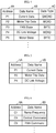
- FIG. 3 is one exemplary view for describing a data library that is stored in the storing unit of the control part of FIG. 2 .
- the control unit 11 may store information regarding a data address 3A, a data name 3B, and a data type 3C in the storing unit 14 as a library.
- the data type 3C may be 'BYTE(an 8-bit unsigned integer)', 'SBYTE(an 8-bit signed integer)', 'WORD(a 16-bit unsigned integer)', 'SWORD(a 16-bit signed integer)', 'LONG(a 32-bit unsigned integer)', 'SLONG(a 32-bit signed integer),' and the like.
- the data name 3B is control data or status data of the control part 10, and, for example, a target frequency, a ramp frequency, a real speed, a control command, a FAN command are shown in the drawing, but the present disclosure is not limited thereto, and various control data or various status data may be stored as a library.
- the communication unit 13 may mutually transmit and receive data to and from the communication unit 23 of the power part 20 under the control of the control unit 11.
- the control unit 21 of the power part 20 may measure and control data (hereinafter, referred to as 'power data') including various signals of the power part 20, a control signal, a PWM signal, a three-phase current, a direct current (DC) link voltage, and the like, and may control the communication unit 23 to communicate with the control part 10.
- 'power data' including various signals of the power part 20, a control signal, a PWM signal, a three-phase current, a direct current (DC) link voltage, and the like, and may control the communication unit 23 to communicate with the control part 10.
- the control unit 21 may store various data in the storing unit 24 as a library.
- FIG. 4 is one exemplary view for describing a data library that is stored in the storing unit of the power part of FIG. 2 .
- the control unit 21 may store information regarding a data address 4A, a data name 4B, and a data type C in the storing unit 24 as a library.
- the data type 4C may be 'BYTE(an 8-bit unsigned integer)', 'SBYTE(an 8-bit signed integer)', 'WORD(a 16-bit unsigned integer)', 'SWORD(a 16-bit signed integer)', 'LONG(a 32-bit unsigned integer)', 'SLONG(a 32-bit signed integer),' and the like.
- the data name 4B is control data and status data of the motor 2, and, for example, current data, motor trip data, a FAN state, a DC link voltage, a motor state, and the like are exemplified, but the present disclosure is not limited thereto, and various motor control data and various status data may be stored as a library.
- an address of a data library may not be changed and thus it may be added to a last position when data is added.
- control unit 11 of the control part 10 may store a data address list of the library of a necessary power part 20, which is stored in the storing unit 24, in the storing unit 14.
- the control unit 21 of the power part 20 may store a data address list of the library of a necessary control part 10, which is stored in the storing unit 14, in the storing unit 24.
- the control unit 11 of the control part 10 and the control unit 21 of the power part 20 may respectively change a data list as necessary.
- FIG. 5 is one exemplary view for describing a data list that is requested to the control unit 21 of the power part 20 by the control unit 11 of the control part 10
- FIG. 6 is one exemplary view for describing a data list that is requested to the control unit 11 of the control part 10 by the control unit 21 of the power part 20.
- the control unit 11 of the control part 10 may request to the storing unit 24 of the power part 20 for a list including a data address 5A of a library and a data name 5B corresponding to the data address 5A, which are stored in the storing unit 24.
- the control unit 61 of the power part 20 may request to the storing unit 14 of the control part 10 for a list including a data address 6A of a library and a data name 6B corresponding to the data address 5A, which are stored in the storing unit 14.
- the control unit 11 of the control part 10 and the control unit 21 of the power part 20 may mutually transmit and receive necessary data through a communication and may create a communication protocol. At this point, the control unit 11 of the control part 10 may operate as a master, and the control unit 21 of the power part 20 may operate as a slave.
- the control unit 11 of the control part 10 may operate as a 'first control unit 11'
- the control unit 21 of the power part 20 may operate as a 'second control unit 21.'
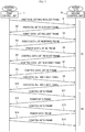
- FIG. 7 is a time flow chart for describing a communication of first and second control units according to one embodiment of the present disclosure
- a section 7A represents a section in which a communication protocol between the control unit 11 and the second control unit 21 is set up
- a section 7B represents a section in which the first control unit 11 and the second control unit 21 transmit and receive data to and from each other.
- FIG. 8 is one exemplary view for describing a data frame that is transmitted and received between the first and second control units according to one embodiment of the present disclosure.
- the first control unit 11 may transmit a protocol setting request frame to the second control unit 21 in Operation S1.
- the second control unit 21 may transmit a protocol setting ready frame to the first control unit 11 in Operation S2.
- the first control unit 11 may transmit a power data list request frame, thereby transmitting an address in a necessary power data list in Operation S3.
- a power data list request frame may include a field 8A representing that an address corresponds to the power data list request frame, a field 8B representing the number of data to be requested, and at least one field 8C representing an address of a power data library.
- the field representing the address of the power data library may be exemplified as configuring with three data sections, but it is apparent that the present disclosure is not limited thereto.
- the second control unit 21 may transmit a power data list response frame, thereby transmitting data type information of data requested by the first control unit 11 in Operation S4.
- a power data list response frame may include a field 8D representing that it corresponds to the power data list response frame, a field 8E representing the number of data requested by the first control unit 11, and at least one field 8F representing a data type of data corresponding to an address of the field 8C in a power data library.
- the first control unit 11 may transmit a power data list OK frame representing that it receives the power data list, thereby noticing that it is ready to receive data to be transmitted from the second control unit 21 in Operation S5.
- the second control unit 21 may transmit a control data list request frame, thereby transmitting an address in a necessary data list in Operation S6.
- a control data list request frame may include a field 8G representing that it corresponds to the control data list request frame, a field 8H representing the number of data to be requested, and at least one field 81 representing an address of a control data library.
- the field representing the address of a control data library is exemplified as configuring with three data sections, but it is apparent that the present disclosure is not limited thereto.
- the first control unit 11 may transmit a control data list response frame with respect to the requested control data list, thereby transmit data corresponding to a data type of the data requested by the second control unit 21 in Operation S7.
- control data list response frame may include a filed 8J representing that it corresponds to the control data list response frame, a field 8K representing the number of data requested by the second control unit 11, and at least one filed 8L representing a data type of a data corresponding to the address of the field 81 in a control data library.
- the second control unit 21 may transmit a control data list OK frame representing that it has received the control data list, thereby noticing that it is ready to receive data to be transmitted from the first control unit 11.
- the first control unit 11 may transmit a protocol setting finish frame for noticing that a setting is finished to the second control unit 21 in Operation S9
- the second control unit 21 may transmit a protocol setting finish frame for noticing that a setting is finished to the first control unit 11 in Operation S10.
- the first control unit 11 and the second unit 21 may transmit and receive set data to and from each other.
- the first control unit 11 may transmit data requested by the second control unit 21 in Operations S11, S13, and S15, and the second control unit 21 may also transit data requested by the first control unit 11.
- control data frame transmitted from the first control unit 11 to the second control unit 21 is shown.
- the control data may be transmitted according to a set order, and a size thereof may be different according to a data type.
- the control data frame may include a field 8M representing that it corresponds to the control data frame, a field 8N representing a length of the control data frame, and a field 8O representing data corresponding to the address 8I of the data requested at FIG. 8C .
- the power data frame may include a field 8P representing that it corresponds to the power data frame, a field 8Q representing a length of the power data frame, and a field 8R representing data corresponding to the address 8C of the data requested at FIG. 8A .
- a field 8P representing that it corresponds to the power data frame
- a field 8Q representing a length of the power data frame
- a field 8R representing data corresponding to the address 8C of the data requested at FIG. 8A .
- the present disclosure automatically create a communication protocol between the control units 11 and 21 of the control part 10 and the power part 20 and data is transmitted and received therebetween. Therefore, when a variety kind of power parts may be added, a separate protocol setting may not be requested so that development period may be reduced and communication efficiency may be increased.
Landscapes
- Engineering & Computer Science (AREA)
- Computer Networks & Wireless Communication (AREA)
- Signal Processing (AREA)
- Power Engineering (AREA)
- Computer Security & Cryptography (AREA)
- Health & Medical Sciences (AREA)
- Computing Systems (AREA)
- General Health & Medical Sciences (AREA)
- Medical Informatics (AREA)
- Inverter Devices (AREA)
- General Induction Heating (AREA)
- Control Of Motors That Do Not Use Commutators (AREA)
Abstract
Description
- The present disclosure relates to an inverter system.
- Generally, an inverter is a device for receiving commercial electric power and applying three-phase power to a motor, and has been developed to have a variety of capacities according to a purpose and a size of the motor.
- When such an inverter is developed, a power part and a control part are developed by being separated from each other for a reduction of development period and work sharing.
FIG. 1 is a block diagram for schematically describing a conventional inverter. For safety and noise countermeasure, a power source is separated between acontrol part 110 of aninverter 100 and apower part 120 thereof. - Conventionally, a single micro-controller unit (MCU) is disposed at the
control part 110, and numerous signals including a pulse width modulation (PWM) control signal, a power part sensor signal, a control part sensor signal, and the like are transmitted and received between thecontrol part 110 and thepower part 120. At this point, because a power source is separately provided in thecontrol part 110 and thepower part 120, the signals are transmitted and received through a plurality of power source separation elements. - In such a case, however, the single MCU executes all software so that there is a problem in which burden for software in such an MCU is increased. Also, all signal cables from the
power part 120 should be insulated from each other such that there is a problem in that component costs are increased. - To address such problems, a control function of an inverter, which was processed in the conventional single MCU, is distributed according to a function and processed in a control part MCU and a power part MCU. That is, an MCU of the
power part 120 controls a PWM, a power part cooling device, and the like, and mutually transmits and receives data to and from an MCU of thecontrol part 110. - At this point, these two MCUs should transmit and receive mutually required information therebetween through a communication. For effectively transmitting and receiving data, a mutual communication protocol is established to perform a communication between the two MCUs.
- In such a case, however, a function of the
power part 120 is changed or required data is different according to capacity so that various protocols are required, and all protocols of thecontrol part 110 and thepower part 120 should be corrected so that there is a problem in that inconvenience of a user may occur. - An object of the present disclosure is to provide an inverter system capable of smoothly transmitting and receiving data without changing a protocol when software is changed or a power part is added.
- To attain the object described above, an inverter system according to one embodiment of the present disclosure may include a storing unit configured to store a control data address, a control data name, and a control data type in a form of a library, and a list of power data addresses stored in a power part, and a second control unit configured to set a communication protocol in association with a first control unit of the power part, and transmit control data and receive power data according to the set communication protocol.
- In one embodiment of the present disclosure, the second control unit may transmit an address with respect to necessary power data, and may receive data type information corresponding to the necessary power data from the first control unit.
- In one embodiment of the present disclosure, the second control unit may transmit data corresponding to the address of the necessary power data to the first control unit.
- In one embodiment of the present disclosure, the second control unit may receive an address with respect to necessary control data from the first control unit, and may transmit data type information corresponding to the necessary control data to the first control unit.
- Also, to attain the object described above, an inverter system according to one embodiment of the present disclosure may include a storing unit configured to store a power data address, a power data name, and a power data type in a form of a library, and a list of control data addresses stored in a control part, and a second control unit configured to set a communication protocol in association with a first control unit of the control part, and transmit power data and receive control data according to the set communication protocol.
- In one embodiment of the present disclosure, the second control unit may transmit an address with respect to necessary control data, and may receive data type information corresponding to the necessary control data from the first control unit.
- In one embodiment of the present disclosure, the second control unit may transmit data corresponding to the address of the necessary control data to the first control unit.
- In one embodiment of the present disclosure, the second control unit may receive an address with respect to necessary power data from the first control unit, and may transmit data type information corresponding to the necessary power data to the first control unit.
- As described above, the present disclosure automatically create a communication protocol between the
control units control part 10 and thepower part 20 and data is transmitted and received therebetween. Therefore, when a variety kind of power parts may be added, a separate protocol setting may not be requested so that there are effects in which development period may be reduced and communication efficiency may be increased. -
-
FIG. 1 is a block diagram for schematically describing a conventional inverter. -
FIG. 2 is a block diagram for schematically describing an inverter system of one embodiment of the present disclosure. -
FIG. 3 is one exemplary view for describing a data library that is stored in a storing unit of a control part. -
FIG. 4 is one exemplary view for describing a data library that is stored in a storing unit of a power part ofFIG. 2 . -
FIG. 5 is one exemplary view for describing a data list that is requested to a control unit of the power part by a control unit of the control part. -
FIG. 6 is one exemplary view for describing a data list that is requested to the control unit of the control part by the control unit of the power part. -
FIG. 7 is a time flow chart for describing a communication of first and second control units according to one embodiment of the present disclosure. -
FIG. 8 is one exemplary view for describing a data frame that is transmitted and received between the first and second control units according to one embodiment of the present disclosure. - The present disclosure may be variously modified and will have a variety of embodiments so that specific embodiments will be exemplified in the drawings and will be described in detail. The specific embodiments disclosed herein, however, are not to be taken in a sense for limiting the present disclosure to these embodiments, but for explanation thereof and it should be understood that numerous other alternations, equivalents and substituents will be falling within the spirit and scope of the present disclosure.
- Hereinafter, one preferred embodiment according to the present disclosure will be described in detail with reference to the accompanying drawings.
-
FIG. 2 is a block diagram for schematically describing an inverter system according to one embodiment of the present disclosure. - As shown in the drawing, an
inverter system 1 is configured to provide a three-phase alternating current (AC) power source to a motor 2, and may include acontrol part 10 and apower part 20. Also, theinverter system 1 may further components in addition to thecontrol part 10 and thepower part 20, and component irrelevant to the present disclosure will be omitted. - In one embodiment of the present disclosure, the
control part 10 may include acontrol unit 11, an input andoutput unit 12, and acommunication unit 13, and astoring unit 14, and thepower part 20 may include acontrol unit 21, aninverter unit 22, acommunication unit 23, and astoring unit 24. - An
inverter unit 22 of thepower part 20 includes a plurality of switching devices (for example, an insulated-gate bipolar transistor (IGBT)). Thecontrol units - The
control unit 11 may control the input andoutput unit 12 to communicate with external devices, and thecommunication unit 13 to communicate with thepower part 20. Also, thecontrol unit 11 may store terminal strip information in thestoring unit 14 and may control operations of various applications. - The
control unit 11 may store numerous data (hereinafter, referred to as 'control data') including control data and status data in the storingunit 14 as a library. -
FIG. 3 is one exemplary view for describing a data library that is stored in the storing unit of the control part ofFIG. 2 . - As shown in
FIG. 3 , thecontrol unit 11 may store information regarding adata address 3A, adata name 3B, and adata type 3C in thestoring unit 14 as a library. At this point, thedata type 3C may be 'BYTE(an 8-bit unsigned integer)', 'SBYTE(an 8-bit signed integer)', 'WORD(a 16-bit unsigned integer)', 'SWORD(a 16-bit signed integer)', 'LONG(a 32-bit unsigned integer)', 'SLONG(a 32-bit signed integer),' and the like. - The
data name 3B is control data or status data of thecontrol part 10, and, for example, a target frequency, a ramp frequency, a real speed, a control command, a FAN command are shown in the drawing, but the present disclosure is not limited thereto, and various control data or various status data may be stored as a library. - Even when the
control part 10 is changed, an address of a data library may not be changed and thus it may be added to a last position when data is added. - The
communication unit 13 may mutually transmit and receive data to and from thecommunication unit 23 of thepower part 20 under the control of thecontrol unit 11. - The
control unit 21 of thepower part 20 may measure and control data (hereinafter, referred to as 'power data') including various signals of thepower part 20, a control signal, a PWM signal, a three-phase current, a direct current (DC) link voltage, and the like, and may control thecommunication unit 23 to communicate with thecontrol part 10. - The
control unit 21 may store various data in thestoring unit 24 as a library.FIG. 4 is one exemplary view for describing a data library that is stored in the storing unit of the power part ofFIG. 2 . - As shown in the drawing, the
control unit 21 may store information regarding adata address 4A, adata name 4B, and a data type C in thestoring unit 24 as a library. Thedata type 4C may be 'BYTE(an 8-bit unsigned integer)', 'SBYTE(an 8-bit signed integer)', 'WORD(a 16-bit unsigned integer)', 'SWORD(a 16-bit signed integer)', 'LONG(a 32-bit unsigned integer)', 'SLONG(a 32-bit signed integer),' and the like. - The
data name 4B is control data and status data of the motor 2, and, for example, current data, motor trip data, a FAN state, a DC link voltage, a motor state, and the like are exemplified, but the present disclosure is not limited thereto, and various motor control data and various status data may be stored as a library. - Even when the
power part 20 is changed, an address of a data library may not be changed and thus it may be added to a last position when data is added. - Also, the
control unit 11 of thecontrol part 10 may store a data address list of the library of anecessary power part 20, which is stored in the storingunit 24, in the storingunit 14. - The
control unit 21 of thepower part 20 may store a data address list of the library of anecessary control part 10, which is stored in the storingunit 14, in the storingunit 24. - The
control unit 11 of thecontrol part 10 and thecontrol unit 21 of thepower part 20 may respectively change a data list as necessary. -
FIG. 5 is one exemplary view for describing a data list that is requested to thecontrol unit 21 of thepower part 20 by thecontrol unit 11 of thecontrol part 10, andFIG. 6 is one exemplary view for describing a data list that is requested to thecontrol unit 11 of thecontrol part 10 by thecontrol unit 21 of thepower part 20. - As shown in
FIG. 5 , thecontrol unit 11 of thecontrol part 10 may request to the storingunit 24 of thepower part 20 for a list including adata address 5A of a library and adata name 5B corresponding to the data address 5A, which are stored in the storingunit 24. As shown inFIG. 6 , the control unit 61 of thepower part 20 may request to the storingunit 14 of thecontrol part 10 for a list including adata address 6A of a library and adata name 6B corresponding to the data address 5A, which are stored in the storingunit 14. - The
control unit 11 of thecontrol part 10 and thecontrol unit 21 of thepower part 20 may mutually transmit and receive necessary data through a communication and may create a communication protocol. At this point, thecontrol unit 11 of thecontrol part 10 may operate as a master, and thecontrol unit 21 of thepower part 20 may operate as a slave. Hereinafter, for the convenience of description, it will be described by referring thecontrol unit 11 of thecontrol part 10 as a 'first control unit 11' and thecontrol unit 21 of thepower part 20 as a 'second control unit 21.' -
FIG. 7 is a time flow chart for describing a communication of first and second control units according to one embodiment of the present disclosure, asection 7A represents a section in which a communication protocol between thecontrol unit 11 and thesecond control unit 21 is set up, and asection 7B represents a section in which thefirst control unit 11 and thesecond control unit 21 transmit and receive data to and from each other.FIG. 8 is one exemplary view for describing a data frame that is transmitted and received between the first and second control units according to one embodiment of the present disclosure. - As shown in
FIG. 7 , in one embodiment of the present disclosure, thefirst control unit 11 may transmit a protocol setting request frame to thesecond control unit 21 in Operation S1. As a response to this request, thesecond control unit 21 may transmit a protocol setting ready frame to thefirst control unit 11 in Operation S2. - The
first control unit 11 may transmit a power data list request frame, thereby transmitting an address in a necessary power data list in Operation S3. Referring toFIG. 8A , one example of the power data list request frame is shown. In one embodiment of the present disclosure, the power data list request frame may include afield 8A representing that an address corresponds to the power data list request frame, afield 8B representing the number of data to be requested, and at least onefield 8C representing an address of a power data library. The field representing the address of the power data library may be exemplified as configuring with three data sections, but it is apparent that the present disclosure is not limited thereto. - The
second control unit 21 may transmit a power data list response frame, thereby transmitting data type information of data requested by thefirst control unit 11 in Operation S4. Referring toFIG. 8B , one example of the power data list response frame is shown. In one embodiment of the present disclosure, the power data list response frame may include afield 8D representing that it corresponds to the power data list response frame, afield 8E representing the number of data requested by thefirst control unit 11, and at least onefield 8F representing a data type of data corresponding to an address of thefield 8C in a power data library. - The
first control unit 11 may transmit a power data list OK frame representing that it receives the power data list, thereby noticing that it is ready to receive data to be transmitted from thesecond control unit 21 in Operation S5. - Also, the
second control unit 21 may transmit a control data list request frame, thereby transmitting an address in a necessary data list in Operation S6. Referring to 8C, one example of the control data list request frame is shown. In one embodiment of the present disclosure, the control data list request frame may include afield 8G representing that it corresponds to the control data list request frame, afield 8H representing the number of data to be requested, and at least onefield 81 representing an address of a control data library. The field representing the address of a control data library is exemplified as configuring with three data sections, but it is apparent that the present disclosure is not limited thereto. - As a response to this request, the
first control unit 11 may transmit a control data list response frame with respect to the requested control data list, thereby transmit data corresponding to a data type of the data requested by thesecond control unit 21 in Operation S7. - Referring to
FIG. 8D , one example of the control data list response frame is shown. In one embodiment of the present disclosure, the control data list response frame may include a filed 8J representing that it corresponds to the control data list response frame, afield 8K representing the number of data requested by thesecond control unit 11, and at least one filed 8L representing a data type of a data corresponding to the address of thefield 81 in a control data library. - The
second control unit 21 may transmit a control data list OK frame representing that it has received the control data list, thereby noticing that it is ready to receive data to be transmitted from thefirst control unit 11. - Thereafter, the
first control unit 11 may transmit a protocol setting finish frame for noticing that a setting is finished to thesecond control unit 21 in Operation S9, and thesecond control unit 21 may transmit a protocol setting finish frame for noticing that a setting is finished to thefirst control unit 11 in Operation S10. - As described above, after the protocol setting is completed, the
first control unit 11 and thesecond unit 21 may transmit and receive set data to and from each other. - That is, the
first control unit 11 may transmit data requested by thesecond control unit 21 in Operations S11, S13, and S15, and thesecond control unit 21 may also transit data requested by thefirst control unit 11. - Referring to
FIG. 8E , one example of a control data frame transmitted from thefirst control unit 11 to thesecond control unit 21 is shown. The control data may be transmitted according to a set order, and a size thereof may be different according to a data type. In one embodiment of the present disclosure, the control data frame may include afield 8M representing that it corresponds to the control data frame, afield 8N representing a length of the control data frame, and a field 8O representing data corresponding to the address 8I of the data requested atFIG. 8C . However, these are merely examples, and thus the control data frame of the present disclosure may further include other fields. - Also, referring to
FIG. 8F , one example of a power data frame transmitted from thesecond control unit 21 to thefirst control unit 11 is show. The power data may be transmitted according to a set order, and a size thereof may be different according to a data type. In one embodiment of the present disclosure, the power data frame may include afield 8P representing that it corresponds to the power data frame, afield 8Q representing a length of the power data frame, and afield 8R representing data corresponding to theaddress 8C of the data requested atFIG. 8A . However, these are merely examples, and thus the power data frame of the present disclosure may further include other fields. - As described above, the present disclosure automatically create a communication protocol between the
control units control part 10 and thepower part 20 and data is transmitted and received therebetween. Therefore, when a variety kind of power parts may be added, a separate protocol setting may not be requested so that development period may be reduced and communication efficiency may be increased. - The present disclosure has been described with reference to the embodiments shown in the drawings, but is merely an illustration, and it should be understood that numerous other modifications and equivalent other embodiments can be devised by those skilled in the art. Therefore, the technical scope of the present invention should be defined by the appended claims.
[Description of Reference Numerals] 1: Inverter System 2: Motor 10: Control Part 20: Power Part 11 and 21: Control Units 12: Input and Output Unit 22: Inverter Unit 13 and 23: Communication Units 14 and 24: Storing Units
Claims (8)
- An inverter system (1) comprising:a storing unit configured to store a control data address, a control data name, and a control data type in a form of a library, and a list of power data addresses stored in a power part; anda first control unit configured to transmit control data and receive power data,wherein the first control unit sets a communication protocol in association with a second control unit of the power part, thereby transmitting the control data and receiving the power data according to the set communication protocol.
- The inverter system of claim 1, wherein the first control unit transmits an address with respect to necessary power data, and receives data type information corresponding to the necessary power data from the second control unit.
- The inverter system of claim 2, wherein the first control unit transmits data corresponding to the address of the necessary power data to the second control unit.
- The inverter system of claim 1, wherein the first control unit receives an address with respect to necessary control data from the second control unit, and transmits data type information corresponding to the necessary control data to the second control unit.
- An inverter system comprising:a storing unit configured to store a power data address, a power data name, and a power data type in a form of a library, and a list of control data addresses stored in a control part; anda second control unit configured to set a communication protocol in association with a first control unit of the control part, and transmit power data and receive control data according to the set communication protocol.
- The inverter system of claim 5, wherein the second control unit transmits an address with respect to necessary control data, and receives data type information corresponding to the necessary control data from the first control unit.
- The inverter system of claim 6, wherein the second control unit transmits data corresponding to the address of the necessary power data to the first control unit.
- The inverter system of claim 5, wherein the second control unit receives an address with respect to necessary power data from the first control unit, and transmits data type information corresponding to the necessary power data to the first control unit.
Applications Claiming Priority (1)
| Application Number | Priority Date | Filing Date | Title |
|---|---|---|---|
| KR1020160043185A KR20170115696A (en) | 2016-04-08 | 2016-04-08 | Inverter system |
Publications (2)
| Publication Number | Publication Date |
|---|---|
| EP3229362A1 true EP3229362A1 (en) | 2017-10-11 |
| EP3229362B1 EP3229362B1 (en) | 2022-08-10 |
Family
ID=57471659
Family Applications (1)
| Application Number | Title | Priority Date | Filing Date |
|---|---|---|---|
| EP16201180.3A Not-in-force EP3229362B1 (en) | 2016-04-08 | 2016-11-29 | Inverter system |
Country Status (6)
| Country | Link |
|---|---|
| US (1) | US10419587B2 (en) |
| EP (1) | EP3229362B1 (en) |
| JP (1) | JP6263599B2 (en) |
| KR (1) | KR20170115696A (en) |
| CN (1) | CN107276972B (en) |
| ES (1) | ES2925693T3 (en) |
Citations (3)
| Publication number | Priority date | Publication date | Assignee | Title |
|---|---|---|---|---|
| US20120331195A1 (en) * | 2011-06-24 | 2012-12-27 | Randall Pipho | Providing Multiple Communication Protocols For A Control System |
| EP2541428A1 (en) * | 2011-06-08 | 2013-01-02 | LSIS Co., Ltd. | Parallel communication device and communication method thereof |
| EP2595304A2 (en) * | 2011-11-18 | 2013-05-22 | Eaton Corporation | Power system controlling and monitoring power semiconductor devices employing two serial signals |
Family Cites Families (20)
| Publication number | Priority date | Publication date | Assignee | Title |
|---|---|---|---|---|
| JPH05153784A (en) * | 1991-11-27 | 1993-06-18 | Mitsubishi Electric Corp | Inverter control device |
| JP3544849B2 (en) * | 1998-01-28 | 2004-07-21 | 株式会社東芝 | Optional communication device for inverter device and communication system using the same |
| JP2004336907A (en) | 2003-05-08 | 2004-11-25 | Denso Corp | Inverter system |
| JP4520132B2 (en) * | 2003-10-31 | 2010-08-04 | 東芝シュネデール・インバータ株式会社 | Inverter system and inverter device |
| CN101145697A (en) * | 2007-09-21 | 2008-03-19 | 北京交通大学 | Battery multi-unit synchronous charging and discharging device and method |
| JP5144409B2 (en) | 2008-07-14 | 2013-02-13 | 東芝シュネデール・インバータ株式会社 | Inverter control system, peripheral equipment of inverter device |
| JP5350723B2 (en) | 2008-09-12 | 2013-11-27 | 東芝シュネデール・インバータ株式会社 | Inverter device |
| EP2189859A1 (en) * | 2008-11-21 | 2010-05-26 | SMA Solar Technology AG | Energy generation system with several power generators with several transformers, e.g. for PV and/or wind power systems |
| US9063525B2 (en) * | 2011-01-28 | 2015-06-23 | Sunverge Energy, Inc. | Distributed energy services management system |
| DE112012005678T5 (en) * | 2012-01-16 | 2014-10-23 | Mitsubishi Electric Corporation | Motor controller |
| WO2013136627A1 (en) * | 2012-03-12 | 2013-09-19 | 富士電機株式会社 | Motor drive system |
| JP6001962B2 (en) * | 2012-08-29 | 2016-10-05 | 東芝シュネデール・インバータ株式会社 | Inverter device |
| EP2993780A4 (en) * | 2013-04-30 | 2017-01-11 | Fuji Electric Co., Ltd. | Controller and map file conversion device |
| JP5971410B2 (en) * | 2013-04-30 | 2016-08-17 | 富士電機株式会社 | Control device and motor drive device |
| EP3032422B1 (en) * | 2013-08-07 | 2019-11-06 | Fuji Electric Co., Ltd. | Monitoring method and computer device |
| CN105122155B (en) * | 2013-09-27 | 2017-07-11 | 富士电机株式会社 | Drive device |
| DE102014107115A1 (en) * | 2014-05-20 | 2015-11-26 | Phoenix Contact Gmbh & Co. Kg | Apparatus and method for controlling decentralized power generation plants |
| WO2016061441A1 (en) * | 2014-10-17 | 2016-04-21 | Princeton Power Systems, Inc. | Energy management system |
| WO2016181504A1 (en) * | 2015-05-12 | 2016-11-17 | 三菱電機株式会社 | Numerical controller device |
| CN105226987A (en) * | 2015-10-21 | 2016-01-06 | 许昌学院 | A kind of inverter control method |
-
2016
- 2016-04-08 KR KR1020160043185A patent/KR20170115696A/en not_active Abandoned
- 2016-11-29 EP EP16201180.3A patent/EP3229362B1/en not_active Not-in-force
- 2016-11-29 CN CN201611073793.5A patent/CN107276972B/en not_active Expired - Fee Related
- 2016-11-29 ES ES16201180T patent/ES2925693T3/en active Active
- 2016-12-02 JP JP2016235317A patent/JP6263599B2/en not_active Expired - Fee Related
- 2016-12-19 US US15/383,022 patent/US10419587B2/en not_active Expired - Fee Related
Patent Citations (3)
| Publication number | Priority date | Publication date | Assignee | Title |
|---|---|---|---|---|
| EP2541428A1 (en) * | 2011-06-08 | 2013-01-02 | LSIS Co., Ltd. | Parallel communication device and communication method thereof |
| US20120331195A1 (en) * | 2011-06-24 | 2012-12-27 | Randall Pipho | Providing Multiple Communication Protocols For A Control System |
| EP2595304A2 (en) * | 2011-11-18 | 2013-05-22 | Eaton Corporation | Power system controlling and monitoring power semiconductor devices employing two serial signals |
Also Published As
| Publication number | Publication date |
|---|---|
| CN107276972B (en) | 2020-07-03 |
| ES2925693T3 (en) | 2022-10-19 |
| JP2017189084A (en) | 2017-10-12 |
| KR20170115696A (en) | 2017-10-18 |
| US20170295262A1 (en) | 2017-10-12 |
| EP3229362B1 (en) | 2022-08-10 |
| JP6263599B2 (en) | 2018-01-17 |
| CN107276972A (en) | 2017-10-20 |
| US10419587B2 (en) | 2019-09-17 |
Similar Documents
| Publication | Publication Date | Title |
|---|---|---|
| US9966893B2 (en) | Single-shunt current sensing for multi-phase motor | |
| CN107395787B (en) | Address allocation method, system, gateway and medium for CAN communication network | |
| JP6825637B2 (en) | Power converter, power conversion system and power conversion method | |
| CN105259806A (en) | Controller upgrading method and system, master controller and slave controller | |
| US9484920B2 (en) | Switching circuit and electronic device | |
| JP6115482B2 (en) | Electronic control unit | |
| EP3229362B1 (en) | Inverter system | |
| US10326659B2 (en) | Device and method for automatic switching of communication protocol of network devices based on user action | |
| CN108697046B (en) | Method for operating an agricultural system having a tractor and a tool, agricultural system and computer program product | |
| CN115225812A (en) | Camera control method and device, electronic equipment and storage medium | |
| CN111426890A (en) | Phase sequence detection circuit, outdoor unit, air conditioner and control method | |
| CN112769966B (en) | Address information distribution method, device and electronic equipment | |
| CN105227041A (en) | The control method of motor driver and motor driven systems | |
| US11381251B2 (en) | Data processing system and method | |
| CN111801199B (en) | Time expansion control period of robot servo motor | |
| EP3206098B1 (en) | Systems and methods for implementing multiple motor control modes in a motor drive controller | |
| US20250317324A1 (en) | Terminal device and communication system | |
| US20250062599A1 (en) | Address assignment apparatus, power distribution cabinet, address assignment method, and storage medium | |
| CN108572732A (en) | Electronic device, black screen gesture detection method and related product | |
| US20150215136A1 (en) | Network control device, the network control system and the method of the remote device | |
| CN116325472A (en) | power conversion system | |
| CN112060076A (en) | Steering engine control method, steering engine control device, terminal and storage medium | |
| CN111385320A (en) | Method and device for expanding Internet of things system | |
| JP2005045931A (en) | Servo control device and its I / O device connection method | |
| JP2019092035A (en) | Communication device, packet generation device, and control method therefor |
Legal Events
| Date | Code | Title | Description |
|---|---|---|---|
| PUAI | Public reference made under article 153(3) epc to a published international application that has entered the european phase |
Free format text: ORIGINAL CODE: 0009012 |
|
| STAA | Information on the status of an ep patent application or granted ep patent |
Free format text: STATUS: THE APPLICATION HAS BEEN PUBLISHED |
|
| AK | Designated contracting states |
Kind code of ref document: A1 Designated state(s): AL AT BE BG CH CY CZ DE DK EE ES FI FR GB GR HR HU IE IS IT LI LT LU LV MC MK MT NL NO PL PT RO RS SE SI SK SM TR |
|
| AX | Request for extension of the european patent |
Extension state: BA ME |
|
| STAA | Information on the status of an ep patent application or granted ep patent |
Free format text: STATUS: REQUEST FOR EXAMINATION WAS MADE |
|
| 17P | Request for examination filed |
Effective date: 20180409 |
|
| RBV | Designated contracting states (corrected) |
Designated state(s): AL AT BE BG CH CY CZ DE DK EE ES FI FR GB GR HR HU IE IS IT LI LT LU LV MC MK MT NL NO PL PT RO RS SE SI SK SM TR |
|
| STAA | Information on the status of an ep patent application or granted ep patent |
Free format text: STATUS: EXAMINATION IS IN PROGRESS |
|
| 17Q | First examination report despatched |
Effective date: 20201207 |
|
| GRAP | Despatch of communication of intention to grant a patent |
Free format text: ORIGINAL CODE: EPIDOSNIGR1 |
|
| STAA | Information on the status of an ep patent application or granted ep patent |
Free format text: STATUS: GRANT OF PATENT IS INTENDED |
|
| RIC1 | Information provided on ipc code assigned before grant |
Ipc: H02P 23/00 20160101ALI20220405BHEP Ipc: H04L 69/18 20220101ALI20220405BHEP Ipc: H04L 67/125 20220101ALI20220405BHEP Ipc: H02M 7/48 20070101AFI20220405BHEP |
|
| INTG | Intention to grant announced |
Effective date: 20220420 |
|
| GRAS | Grant fee paid |
Free format text: ORIGINAL CODE: EPIDOSNIGR3 |
|
| GRAA | (expected) grant |
Free format text: ORIGINAL CODE: 0009210 |
|
| STAA | Information on the status of an ep patent application or granted ep patent |
Free format text: STATUS: THE PATENT HAS BEEN GRANTED |
|
| AK | Designated contracting states |
Kind code of ref document: B1 Designated state(s): AL AT BE BG CH CY CZ DE DK EE ES FI FR GB GR HR HU IE IS IT LI LT LU LV MC MK MT NL NO PL PT RO RS SE SI SK SM TR |
|
| REG | Reference to a national code |
Ref country code: AT Ref legal event code: REF Ref document number: 1511312 Country of ref document: AT Kind code of ref document: T Effective date: 20220815 Ref country code: CH Ref legal event code: EP |
|
| REG | Reference to a national code |
Ref country code: IE Ref legal event code: FG4D |
|
| REG | Reference to a national code |
Ref country code: DE Ref legal event code: R096 Ref document number: 602016074112 Country of ref document: DE |
|
| REG | Reference to a national code |
Ref country code: ES Ref legal event code: FG2A Ref document number: 2925693 Country of ref document: ES Kind code of ref document: T3 Effective date: 20221019 |
|
| REG | Reference to a national code |
Ref country code: NL Ref legal event code: MP Effective date: 20220810 |
|
| REG | Reference to a national code |
Ref country code: LT Ref legal event code: MG9D |
|
| PG25 | Lapsed in a contracting state [announced via postgrant information from national office to epo] |
Ref country code: SE Free format text: LAPSE BECAUSE OF FAILURE TO SUBMIT A TRANSLATION OF THE DESCRIPTION OR TO PAY THE FEE WITHIN THE PRESCRIBED TIME-LIMIT Effective date: 20220810 Ref country code: RS Free format text: LAPSE BECAUSE OF FAILURE TO SUBMIT A TRANSLATION OF THE DESCRIPTION OR TO PAY THE FEE WITHIN THE PRESCRIBED TIME-LIMIT Effective date: 20220810 Ref country code: PT Free format text: LAPSE BECAUSE OF FAILURE TO SUBMIT A TRANSLATION OF THE DESCRIPTION OR TO PAY THE FEE WITHIN THE PRESCRIBED TIME-LIMIT Effective date: 20221212 Ref country code: NO Free format text: LAPSE BECAUSE OF FAILURE TO SUBMIT A TRANSLATION OF THE DESCRIPTION OR TO PAY THE FEE WITHIN THE PRESCRIBED TIME-LIMIT Effective date: 20221110 Ref country code: NL Free format text: LAPSE BECAUSE OF FAILURE TO SUBMIT A TRANSLATION OF THE DESCRIPTION OR TO PAY THE FEE WITHIN THE PRESCRIBED TIME-LIMIT Effective date: 20220810 Ref country code: LV Free format text: LAPSE BECAUSE OF FAILURE TO SUBMIT A TRANSLATION OF THE DESCRIPTION OR TO PAY THE FEE WITHIN THE PRESCRIBED TIME-LIMIT Effective date: 20220810 Ref country code: LT Free format text: LAPSE BECAUSE OF FAILURE TO SUBMIT A TRANSLATION OF THE DESCRIPTION OR TO PAY THE FEE WITHIN THE PRESCRIBED TIME-LIMIT Effective date: 20220810 Ref country code: FI Free format text: LAPSE BECAUSE OF FAILURE TO SUBMIT A TRANSLATION OF THE DESCRIPTION OR TO PAY THE FEE WITHIN THE PRESCRIBED TIME-LIMIT Effective date: 20220810 |
|
| REG | Reference to a national code |
Ref country code: AT Ref legal event code: MK05 Ref document number: 1511312 Country of ref document: AT Kind code of ref document: T Effective date: 20220810 |
|
| PG25 | Lapsed in a contracting state [announced via postgrant information from national office to epo] |
Ref country code: PL Free format text: LAPSE BECAUSE OF FAILURE TO SUBMIT A TRANSLATION OF THE DESCRIPTION OR TO PAY THE FEE WITHIN THE PRESCRIBED TIME-LIMIT Effective date: 20220810 Ref country code: IS Free format text: LAPSE BECAUSE OF FAILURE TO SUBMIT A TRANSLATION OF THE DESCRIPTION OR TO PAY THE FEE WITHIN THE PRESCRIBED TIME-LIMIT Effective date: 20221210 Ref country code: HR Free format text: LAPSE BECAUSE OF FAILURE TO SUBMIT A TRANSLATION OF THE DESCRIPTION OR TO PAY THE FEE WITHIN THE PRESCRIBED TIME-LIMIT Effective date: 20220810 Ref country code: GR Free format text: LAPSE BECAUSE OF FAILURE TO SUBMIT A TRANSLATION OF THE DESCRIPTION OR TO PAY THE FEE WITHIN THE PRESCRIBED TIME-LIMIT Effective date: 20221111 |
|
| PG25 | Lapsed in a contracting state [announced via postgrant information from national office to epo] |
Ref country code: SM Free format text: LAPSE BECAUSE OF FAILURE TO SUBMIT A TRANSLATION OF THE DESCRIPTION OR TO PAY THE FEE WITHIN THE PRESCRIBED TIME-LIMIT Effective date: 20220810 Ref country code: RO Free format text: LAPSE BECAUSE OF FAILURE TO SUBMIT A TRANSLATION OF THE DESCRIPTION OR TO PAY THE FEE WITHIN THE PRESCRIBED TIME-LIMIT Effective date: 20220810 Ref country code: DK Free format text: LAPSE BECAUSE OF FAILURE TO SUBMIT A TRANSLATION OF THE DESCRIPTION OR TO PAY THE FEE WITHIN THE PRESCRIBED TIME-LIMIT Effective date: 20220810 Ref country code: CZ Free format text: LAPSE BECAUSE OF FAILURE TO SUBMIT A TRANSLATION OF THE DESCRIPTION OR TO PAY THE FEE WITHIN THE PRESCRIBED TIME-LIMIT Effective date: 20220810 Ref country code: AT Free format text: LAPSE BECAUSE OF FAILURE TO SUBMIT A TRANSLATION OF THE DESCRIPTION OR TO PAY THE FEE WITHIN THE PRESCRIBED TIME-LIMIT Effective date: 20220810 |
|
| REG | Reference to a national code |
Ref country code: DE Ref legal event code: R097 Ref document number: 602016074112 Country of ref document: DE |
|
| PG25 | Lapsed in a contracting state [announced via postgrant information from national office to epo] |
Ref country code: SK Free format text: LAPSE BECAUSE OF FAILURE TO SUBMIT A TRANSLATION OF THE DESCRIPTION OR TO PAY THE FEE WITHIN THE PRESCRIBED TIME-LIMIT Effective date: 20220810 Ref country code: EE Free format text: LAPSE BECAUSE OF FAILURE TO SUBMIT A TRANSLATION OF THE DESCRIPTION OR TO PAY THE FEE WITHIN THE PRESCRIBED TIME-LIMIT Effective date: 20220810 |
|
| REG | Reference to a national code |
Ref country code: DE Ref legal event code: R119 Ref document number: 602016074112 Country of ref document: DE |
|
| PLBE | No opposition filed within time limit |
Free format text: ORIGINAL CODE: 0009261 |
|
| STAA | Information on the status of an ep patent application or granted ep patent |
Free format text: STATUS: NO OPPOSITION FILED WITHIN TIME LIMIT |
|
| PG25 | Lapsed in a contracting state [announced via postgrant information from national office to epo] |
Ref country code: MC Free format text: LAPSE BECAUSE OF FAILURE TO SUBMIT A TRANSLATION OF THE DESCRIPTION OR TO PAY THE FEE WITHIN THE PRESCRIBED TIME-LIMIT Effective date: 20220810 Ref country code: AL Free format text: LAPSE BECAUSE OF FAILURE TO SUBMIT A TRANSLATION OF THE DESCRIPTION OR TO PAY THE FEE WITHIN THE PRESCRIBED TIME-LIMIT Effective date: 20220810 |
|
| REG | Reference to a national code |
Ref country code: CH Ref legal event code: PL |
|
| 26N | No opposition filed |
Effective date: 20230511 |
|
| GBPC | Gb: european patent ceased through non-payment of renewal fee |
Effective date: 20221129 |
|
| REG | Reference to a national code |
Ref country code: BE Ref legal event code: MM Effective date: 20221130 |
|
| PG25 | Lapsed in a contracting state [announced via postgrant information from national office to epo] |
Ref country code: LI Free format text: LAPSE BECAUSE OF NON-PAYMENT OF DUE FEES Effective date: 20221130 Ref country code: CH Free format text: LAPSE BECAUSE OF NON-PAYMENT OF DUE FEES Effective date: 20221130 |
|
| PG25 | Lapsed in a contracting state [announced via postgrant information from national office to epo] |
Ref country code: SI Free format text: LAPSE BECAUSE OF FAILURE TO SUBMIT A TRANSLATION OF THE DESCRIPTION OR TO PAY THE FEE WITHIN THE PRESCRIBED TIME-LIMIT Effective date: 20220810 Ref country code: LU Free format text: LAPSE BECAUSE OF NON-PAYMENT OF DUE FEES Effective date: 20221129 |
|
| PG25 | Lapsed in a contracting state [announced via postgrant information from national office to epo] |
Ref country code: IT Free format text: LAPSE BECAUSE OF NON-PAYMENT OF DUE FEES Effective date: 20221129 Ref country code: IE Free format text: LAPSE BECAUSE OF NON-PAYMENT OF DUE FEES Effective date: 20221129 Ref country code: GB Free format text: LAPSE BECAUSE OF NON-PAYMENT OF DUE FEES Effective date: 20221129 Ref country code: DE Free format text: LAPSE BECAUSE OF NON-PAYMENT OF DUE FEES Effective date: 20230601 |
|
| PG25 | Lapsed in a contracting state [announced via postgrant information from national office to epo] |
Ref country code: FR Free format text: LAPSE BECAUSE OF NON-PAYMENT OF DUE FEES Effective date: 20221130 Ref country code: BE Free format text: LAPSE BECAUSE OF NON-PAYMENT OF DUE FEES Effective date: 20221130 |
|
| REG | Reference to a national code |
Ref country code: ES Ref legal event code: FD2A Effective date: 20240102 |
|
| PG25 | Lapsed in a contracting state [announced via postgrant information from national office to epo] |
Ref country code: ES Free format text: LAPSE BECAUSE OF NON-PAYMENT OF DUE FEES Effective date: 20221130 |
|
| PG25 | Lapsed in a contracting state [announced via postgrant information from national office to epo] |
Ref country code: ES Free format text: LAPSE BECAUSE OF NON-PAYMENT OF DUE FEES Effective date: 20221130 |
|
| PG25 | Lapsed in a contracting state [announced via postgrant information from national office to epo] |
Ref country code: HU Free format text: LAPSE BECAUSE OF FAILURE TO SUBMIT A TRANSLATION OF THE DESCRIPTION OR TO PAY THE FEE WITHIN THE PRESCRIBED TIME-LIMIT; INVALID AB INITIO Effective date: 20161129 |
|
| PG25 | Lapsed in a contracting state [announced via postgrant information from national office to epo] |
Ref country code: CY Free format text: LAPSE BECAUSE OF FAILURE TO SUBMIT A TRANSLATION OF THE DESCRIPTION OR TO PAY THE FEE WITHIN THE PRESCRIBED TIME-LIMIT Effective date: 20220810 |
|
| PG25 | Lapsed in a contracting state [announced via postgrant information from national office to epo] |
Ref country code: MK Free format text: LAPSE BECAUSE OF FAILURE TO SUBMIT A TRANSLATION OF THE DESCRIPTION OR TO PAY THE FEE WITHIN THE PRESCRIBED TIME-LIMIT Effective date: 20220810 |
|
| PG25 | Lapsed in a contracting state [announced via postgrant information from national office to epo] |
Ref country code: BG Free format text: LAPSE BECAUSE OF FAILURE TO SUBMIT A TRANSLATION OF THE DESCRIPTION OR TO PAY THE FEE WITHIN THE PRESCRIBED TIME-LIMIT Effective date: 20220810 |
|
| PG25 | Lapsed in a contracting state [announced via postgrant information from national office to epo] |
Ref country code: MT Free format text: LAPSE BECAUSE OF FAILURE TO SUBMIT A TRANSLATION OF THE DESCRIPTION OR TO PAY THE FEE WITHIN THE PRESCRIBED TIME-LIMIT Effective date: 20220810 |
|
| PG25 | Lapsed in a contracting state [announced via postgrant information from national office to epo] |
Ref country code: TR Free format text: LAPSE BECAUSE OF FAILURE TO SUBMIT A TRANSLATION OF THE DESCRIPTION OR TO PAY THE FEE WITHIN THE PRESCRIBED TIME-LIMIT Effective date: 20220810 |