EP3229324A1 - Electrical cable retention - Google Patents
Electrical cable retention Download PDFInfo
- Publication number
- EP3229324A1 EP3229324A1 EP17164177.2A EP17164177A EP3229324A1 EP 3229324 A1 EP3229324 A1 EP 3229324A1 EP 17164177 A EP17164177 A EP 17164177A EP 3229324 A1 EP3229324 A1 EP 3229324A1
- Authority
- EP
- European Patent Office
- Prior art keywords
- clamping member
- rib
- assembly
- cable
- electrical
- Prior art date
- Legal status (The legal status is an assumption and is not a legal conclusion. Google has not performed a legal analysis and makes no representation as to the accuracy of the status listed.)
- Granted
Links
Images


Classifications
-
- H—ELECTRICITY
- H01—ELECTRIC ELEMENTS
- H01R—ELECTRICALLY-CONDUCTIVE CONNECTIONS; STRUCTURAL ASSOCIATIONS OF A PLURALITY OF MUTUALLY-INSULATED ELECTRICAL CONNECTING ELEMENTS; COUPLING DEVICES; CURRENT COLLECTORS
- H01R13/00—Details of coupling devices of the kinds covered by groups H01R12/70 or H01R24/00 - H01R33/00
- H01R13/58—Means for relieving strain on wire connection, e.g. cord grip, for avoiding loosening of connections between wires and terminals within a coupling device terminating a cable
- H01R13/5804—Means for relieving strain on wire connection, e.g. cord grip, for avoiding loosening of connections between wires and terminals within a coupling device terminating a cable comprising a separate cable clamping part
- H01R13/5812—Means for relieving strain on wire connection, e.g. cord grip, for avoiding loosening of connections between wires and terminals within a coupling device terminating a cable comprising a separate cable clamping part the cable clamping being achieved by mounting the separate part on the housing of the coupling device
-
- H—ELECTRICITY
- H02—GENERATION; CONVERSION OR DISTRIBUTION OF ELECTRIC POWER
- H02G—INSTALLATION OF ELECTRIC CABLES OR LINES, OR OF COMBINED OPTICAL AND ELECTRIC CABLES OR LINES
- H02G3/00—Installations of electric cables or lines or protective tubing therefor in or on buildings, equivalent structures or vehicles
- H02G3/30—Installations of cables or lines on walls, floors or ceilings
- H02G3/32—Installations of cables or lines on walls, floors or ceilings using mounting clamps
Definitions
- the present invention relates to an assembly for securing an electrical cable to a body.
- the present invention further relates to an electrical appliance such as a luminaire comprising at least part of such an assembly.
- the present invention yet further relates to a method of securing an electrical cable to a body of an electrical appliance using such an assembly.
- Mains-powered electrical appliances are typically connected to a mains power supply through an electrical cable that connects to the mains power supply with a plug.
- the electrical cable is appropriately secured to the electrical appliance for safety reasons.
- the electrical cable should remain secured to the electrical appliance such that the live terminals of the electrical cable cannot become exposed due to the electrical cable disconnecting from the electrical appliance, which would cause an immediate safety hazard.
- CCC China Compulsory Certification
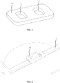
- FIG. 1 schematically depicts a prior art clamp 10 having a pair of cable thread holes 11 through which an electrical cable 1 may be threaded to secure the cable to the clamp 10.
- FIG. 2 schematically depicts the electrical cable 1 threaded through the cable thread holes 11 of the clamp 10.
- the cable thread holes 11 are typically dimensioned such that the electrical cable 1 snugly fits into the cable thread holes 11, thereby retaining the electrical cable 1 through friction.
- Such a clamp 10 for example may be used to prevent coiling of the electrical cable 1, but is unsuitable for retaining the electrical cable 1 in an electrical appliance because the clamp 10 cannot be easily secured to or within the electrical appliance.
- FIG. 3 schematically depicts a well-known assembly for securing an electrical cable to the body of an electrical appliance.
- the assembly comprises a bridge member 20 having opposing cylindrical body portions 22 including screw holes 21 for receiving screws 23.
- the opposing cylindrical body portions 22 are interconnected by a bridge portion 24 spanning over a gap 25 for receiving the electrical cable 1.
- the height of the gap 25 is typically less than the thickness of the electrical cable 1 such that when the bridge member 20 is screwed to an anchoring member 27 on the body 3 of the electrical appliance using the screws 23 as schematically depicted in FIG. 4 , the resilient electrical cable 1 is squeezed (gripped) between the bridge member 20 and the anchoring member 27. Consequently, the release of the live terminals of the electrical from the electrical connectors 4 of the electrical appliance is prevented by this assembly if the electrical cable 1 is suddenly pulled.
- this assembly ensures that the electrical cable 1 is safely secured to the electrical appliance
- a drawback of this assembly is that it requires a hand tool, e.g. a screwdriver, to secure the electrical cable 1 onto the electrical appliance. This can be cumbersome in particular in situations where the electrical appliance needs to be installed in a space that is difficult to access, for example the installation of a luminaire in a ceiling, where the electrical cable 1 is typically hidden in a dead space above the ceiling that can only be accessed through the holes in the ceiling in which the luminaire is to be fitted.
- GB 2 300 219 A discloses an assembly for clamping a cable relative to a body.
- the assembly comprises a clamping element having clamping surfaces between which, in use, the cable is disposed; and a formation on said body adapted to engage with said clamping element to cause said clamping surfaces of said element tightly to grip a cable disposed therebetween.
- This assembly is relatively complex and therefore costly.
- the present invention seeks to provide an inexpensive assembly for securing an electrical cable to a body of an electrical appliance that does not require the use of hand tools to secure the electrical cable to the electrical appliance.
- the present invention further seeks to provide an electrical appliance including at least part of such an assembly.
- the present invention yet further seeks to provide a method of securing an electrical cable to the body of an electrical appliance using such an assembly.
- an assembly for securing an electrical cable to a body of an electrical appliance comprising a clamping member comprising a pair of spatially separated cable holes dimensioned to receive the electrical cable and a pair of guide channels inwardly extending from opposing edges of the clamping member; and a pair of anchoring members for securing the clamping member to the body, each anchoring member comprising a major surface transversely extending from a mounting surface, the major surface having an edge region defining a guide rail for engaging with one of the guide channels and a pair of spatially separated ribs extending from the edge region across said major surface for retaining the clamping member.
- Such an assembly allows for the securing of the electrical cable to the body of the electrical appliance without the need for a hand tool because the electrical cable simply can be threaded through the spatially separated cable holes of the clamping member similar to the clamping member as shown in FIG. 1 , after which the clamping member including the electrical cable can be secured in between the pair of anchoring members by engaging the guide channels with the guide rails of the opposing anchoring members, e.g. by downwardly sliding the clamping member along the guide rails until the clamping member is secured in between the spatially separated ribs of the respective anchoring members.
- the spatially separated ribs of the respective anchoring members prevent twisting (out of plane rotation) of the clamping member, whereas the major surfaces prevent in plane translation of the clamping member, thereby effectively securing the electrical cable to the body of the electrical appliance.
- the pair of spatially separated ribs includes a first rib and a second rib, wherein the first rib is shaped to allow irreversible passage of the clamping member along the guide rail towards the second rib; and the second rib is shaped to prevent passage of the clamping member along the guide rail beyond the second rib.
- the clamping member may be irreversibly retained between the pair of spatially separated ribs, thus effectively securing the electrical cable to the body of the electrical appliance.
- the first rib may have a first surface that gradually increases the thickness of the guide rail, such that the guide channel can be gradually forced over the first surface.
- the first rib may have a triangular cross-section including a surface section normal to the major surface, the surface section facing the second rib.
- the sloped surface portion of the triangular cross-section i.e. the first surface portion, facilitates the gradual forcing of the guide channel over the first rib, whereas the surface section facing the second rib provides a step in the thickness of the guide rail that prevents the clamping member from travelling in the opposite direction over the first rib.
- the second rib may have a rectangular cross-section to provide a step in the thickness of the guide rail that prevents the clamping member from travelling beyond the second rib.
- Each anchoring member may further comprise a further rib on the major surface, the further rib extending from the second rib to the mounting surface in order to increase the structural integrity of the anchoring member.
- a further rib may be outwardly tapering in the direction of the mounting surface.
- the anchoring members may be separate members. However, to avoid the need of having to accurately space the anchoring members, the pair of anchoring members may be adjoined by a mounting plate comprising their respective mounting surfaces.
- the spatially separated cable holes of the clamping member may be separated by a body portion of the clamping member, wherein the guide channels of the clamping member extend into said body portion. This provides a clamping member having good structural integrity that can be easily manufactured.
- the clamping member is plate-shaped to facilitate engagement of the clamping member with the pair of anchoring members.
- the clamping member and a pair of anchoring members may be made of any suitable material.
- the clamping member and the pair of anchoring members are individually made of plastic, a metal or a metal alloy. These materials are particularly preferred because it allows the clamping member and the anchoring members to be manufactured in inexpensive manner.
- an electrical appliance comprising a body comprising at least the anchoring members of the assembly according to embodiments of the present invention.
- the anchoring members are integral to the body of the electrical appliance such that an installer of the electrical appliance does not have to secure the anchoring members to the electrical appliance body.
- the anchoring members are formed as an integral part of the body of the electrical appliance, e.g. by moulding the body including the anchoring members using moulding techniques such as injection moulding, a particularly robust anchoring of the mounting plate to the body of the electrical appliance can be achieved.
- the electrical appliance is a luminaire such as a ceiling down lighter although the teachings of the present invention may be applied to any electrical appliance.
- a method of securing an electrical cable to a body of an electrical appliance using the assembly according to any of the embodiments of the present invention comprising securing the anchoring members to the body; securing the electrical cable in the cable holes of the clamping member; and sliding the guide channels of the clamping member including the secured electrical cable along the guide rails of the anchoring members to secure the clamping member between respective pairs of spatially separated ribs.
- the step of securing the anchoring met members to the body of the electrical appliance comprises forming the anchoring members integral to the body of the electrical appliance although alternative embodiments, embodiments in which the anchoring members are secured to a body of the electrical appliance separate to the anchoring members may also be contemplated.
- FIG. 5 schematically depicts a cable clamping member 30 of an electrical cable securing assembly according to an embodiment of the present invention.
- the clamping member 30 is shaped as a plate having a thickness T and comprising two spatially separated cable holes 31 through which an electrical cable 1 may be threaded, as schematically depicted in FIG. 6 .
- the cable holes 31 are typically shaped such that they match the cross-sectional shape of the electrical cable 1. For example, in case of an electrical cable 1 having a circular cross-section, the cable holes 31 will have a circular shape, and so on.
- the cable holes 31 may be separated by a body portion 35 of the clamping member 30.
- the body portion 35 may carry an optional rib arrangement including a pair of ribs 37 extending between the cable holes 31 and a cross-rib 39 extending between the pair of ribs 37 that may assist in retaining the electrical cable 1.
- the clamping member 30 further comprises a pair of guide channels 33 that are inwardly extending from opposing edges 34 of the clamping member 30.
- the guide channels 33 preferably extend towards each other into the body portion 35 of the clamping member 30.
- Each guide channel 33 has a width W' dimensioned to receive a guide rail of an anchoring member of the assembly as will be explained in further detail below.
- the clamping member 30 may be manufactured in any suitable manner from any suitable material.
- the clamping member 30 may be stamped or molded using a material such as a metal, metal alloy or a plastic or polymer material.
- the clamping member 30 may comprise a maximum width W, which may be the maximum width of the clamping member 30 in between the opposing edges 34 of the clamping member 30.
- the electrical cable securing assembly further comprises a pair of anchoring members 40, which are schematically depicted in FIG. 7 on the body 3 of an electrical appliance 100.
- the anchoring members 40 are typically spaced apart by a gap G having a dimension less than the full width W of the clamping member 30, i.e. G ⁇ W.
- Each anchoring member 40 comprises a mounting surface for contacting the body 3 of the electrical appliance.
- an installer using the electrical cable securing assembly may need to manually position the respective anchoring members 40 such that the respective anchoring members 40 are appropriately aligned and separated by the intended gap G.
- the anchoring members 40 may be mounted on a mounting plate 48 such that an installer using the electrical cable securing assembly does not have to manually position the anchoring members 40 because they are pre-positioned in the correct position on the mounting plate 48.
- the mounting surfaces of anchoring members 40 may be secured on to the body 3 of the electrical appliance 100 in any suitable manner.
- the body 3 may comprise an engagement member arrangement, e.g. a slide rail arrangement or the like for receiving the anchoring members 40 or the mounting plate 48.
- the mounting surfaces of the anchoring members 40 or mounting plate 48 may comprise a strong adhesive for bonding the anchoring members 40 or mounting plate 48 to the body 3 of the electrical appliance 100.
- a hook and eye arrangement may be provided in which an anchoring member 40 or a mounting plate 48 comprises a hook and the body 3 of the electrical appliance 100 comprises an eye (or vice versa) for securing the anchoring members 40 to the electrical appliance 100.
- the anchoring members 40 form an integral part of the body 3 of the electrical appliance 100.
- the body 3 may be a molded body, e.g. formed by injection molding or the like, in which the anchoring members 40 form part of the body 3, e.g. form part of the housing of the electrical appliance 100.
- Each anchoring member 40 has a major surface 41 that transversely extends from its mounting surface, e.g. from the body 3.
- each major surface 41 may perpendicularly extend from its mounting surface.
- Each major surface 41 further comprises an edge, wherein the respective edges of the pair of anchoring members 40 face each other across the gap G.
- These edges define respective guide rails 42 for the guide channels 33 of the cable clamping member 30, wherein the width W' of the guide channels 33 allows the guide channels 33 to receive a respective guide rail 42 of an anchoring member 40.
- Each anchoring member 40 further comprises a first rib 43 and a second rib 44 extending from the edge region defining part of the guide channel 42 across at least a part of the major surface 41.
- the first rib 43 and the second rib 44 may extend across the full width of the major surface 41 in some embodiments (as shown in FIG. 7 ) although this is not essential.
- the first rib 43 is spatially separated from the second rib 44 such that a channel 45 is delimited by the first rib 43 and the second rib 44.
- the channel 45 typically has a height as defined by the distance between the first rib 43 and the second rib 44 that matches the thickness T of the cable clamping member 30, i.e. the channel 45 is dimensioned to receive the cable clamping member 30.
- the first rib 43 may be shaped to allow irreversible passage of the clamping member 30 along the guide rail 42 towards the second rib 44.
- the first rib 43 first rib may have a first surface that gradually increases the thickness of the guide rail 42, such that the guide channel 33 of the clamping member 30 can be gradually forced over the first surface.
- the first rib 43 may have a triangular cross-section, in which the inclined upper surface allows the clamping member 30 to be forced into the channel 45.
- the surface section of the first rib 43 that faces the second rib 45 may be normal to the major surface 41 to provide a step in the thickness of the guide rail 42 that prevents the clamping member 30 from travelling in the opposite direction over the first rib 43.
- the first rib 43 may have any suitable alternative cross-section that facilitates the irreversible passage of the clamping member 30 along the guide rail 42 towards the second rib 44.
- the upper surface of the first rib 43 may be curved surface rather than a planar surface as shown in FIG. 7 .
- the second rib 44 is typically shaped to prevent the clamping member 30 from travelling along the guide rail 42 beyond the second rib 44, such that the clamping member 30 is retained in the channel 45 between the first rib 43 and the second rib 44.
- the second rib 44 have a rectangular cross-section to provide a step in the thickness of the guide rail that prevents the clamping member 30 from travelling beyond the second rib 44.
- Each anchoring member 40 optionally may further comprise one or more reinforcement ribs for reinforcing and/or stabilising the anchoring member 40.
- each anchoring member 40 may comprise a further rib 46 on the major surface 41 extending from the second rib 44 to the mounting surface of the anchoring member 40 e.g. extending to the body 3 of the electrical appliance 100.
- Such a further rib 46 for example may be outwardly tapering in the direction of the mounting surface to provide the desired stability and/or structural integrity of the anchoring member 40.
- the anchoring members 40 in FIG. 7 comprise a further stabilizing rib 47 extending from a further major surface opposite the major surface 41.
- the anchoring members 40 may be made in any suitable manner using any suitable material.
- the anchoring members 40 may be stamped or molded using a material such as a metal, metal alloy or a plastic or polymer material.
- the anchoring members 40 are formed as part of the body 3 of the electrical appliance to provide a particularly robust anchoring mechanism for the electrical cable 1 secured within the cable clamping member 30.
- the body 3 may comprise a cable entry hole 5 through which the electrical cable 1 may be inserted into the electrical appliance 100 for connection to the electrical terminals 4 (not shown in FIG. 7 ) of the electrical appliance 100.
- the installer may thread the electrical cable 1 through the cable entry hole 5 of the body or housing 3 of the electrical appliance 100 after which the installer may thread the electrical cable 1 through the cable clamping member 30 of the electrical cable securing assembly according to embodiments of the present invention as shown in FIG. 6 after which the installer may slide the guide channels 33 of the clamping member 30 including the secured electrical cable 1 along the guide rails 42 of the anchoring members 40 to secure the clamping member 30 in the channel 45 between the first rib 43 and the second rib 44 of the respective anchoring members 40 as schematically depicted in FIG. 8 to secure the electrical cable 1 to the body 3 of the electrical appliance 100.
- FIG. 9 An example embodiment of such an electrical appliance 100 is schematically depicted in FIG. 9 .
- the electrical appliance 100 is a luminaire such as a ceiling spotlight comprising spring-loaded support members 110 for immobilizing the luminaire on an upper surface of the ceiling.
- An electrical cable 1 is secured inside the body 3 using the electrical cable securing assembly according to an embodiment of the present invention as previously explained, with the electrical cable 1 entering the luminaire through the cable entry hole 5.
- the electrical appliance 100 is a luminaire such as a ceiling spotlight
- the electrical cable securing assembly of the present invention may be used for any type of electrical appliance, with at least the anchoring members 40 optionally forming an integral part of the body or housing of such an electrical appliance.
Landscapes
- Engineering & Computer Science (AREA)
- Architecture (AREA)
- Civil Engineering (AREA)
- Structural Engineering (AREA)
- Installation Of Indoor Wiring (AREA)
- Connection Of Plates (AREA)
- Arrangement Of Elements, Cooling, Sealing, Or The Like Of Lighting Devices (AREA)
- Non-Portable Lighting Devices Or Systems Thereof (AREA)
- Insertion, Bundling And Securing Of Wires For Electric Apparatuses (AREA)
- Details Of Connecting Devices For Male And Female Coupling (AREA)
Abstract
Description
- The present invention relates to an assembly for securing an electrical cable to a body.
- The present invention further relates to an electrical appliance such as a luminaire comprising at least part of such an assembly.
- The present invention yet further relates to a method of securing an electrical cable to a body of an electrical appliance using such an assembly.
- Mains-powered electrical appliances are typically connected to a mains power supply through an electrical cable that connects to the mains power supply with a plug. In many countries, it is a regulatory requirement that the electrical cable is appropriately secured to the electrical appliance for safety reasons. For example, in case of the electrical cable being pulled, the electrical cable should remain secured to the electrical appliance such that the live terminals of the electrical cable cannot become exposed due to the electrical cable disconnecting from the electrical appliance, which would cause an immediate safety hazard. For example, in China, the China Compulsory Certification (CCC) regulation requires that an electrical wire connected to an electrical appliance such as a luminaire is secured to the appliance for this reason.
- Several solutions exist for securing electrical cables.
FIG. 1 schematically depicts aprior art clamp 10 having a pair ofcable thread holes 11 through which anelectrical cable 1 may be threaded to secure the cable to theclamp 10.FIG. 2 schematically depicts theelectrical cable 1 threaded through thecable thread holes 11 of theclamp 10. Thecable thread holes 11 are typically dimensioned such that theelectrical cable 1 snugly fits into thecable thread holes 11, thereby retaining theelectrical cable 1 through friction. Such aclamp 10 for example may be used to prevent coiling of theelectrical cable 1, but is unsuitable for retaining theelectrical cable 1 in an electrical appliance because theclamp 10 cannot be easily secured to or within the electrical appliance. -
FIG. 3 schematically depicts a well-known assembly for securing an electrical cable to the body of an electrical appliance. The assembly comprises abridge member 20 having opposingcylindrical body portions 22 includingscrew holes 21 for receivingscrews 23. The opposingcylindrical body portions 22 are interconnected by abridge portion 24 spanning over agap 25 for receiving theelectrical cable 1. The height of thegap 25 is typically less than the thickness of theelectrical cable 1 such that when thebridge member 20 is screwed to ananchoring member 27 on thebody 3 of the electrical appliance using thescrews 23 as schematically depicted inFIG. 4 , the resilientelectrical cable 1 is squeezed (gripped) between thebridge member 20 and theanchoring member 27. Consequently, the release of the live terminals of the electrical from the electrical connectors 4 of the electrical appliance is prevented by this assembly if theelectrical cable 1 is suddenly pulled. - Although this assembly ensures that the
electrical cable 1 is safely secured to the electrical appliance, a drawback of this assembly is that it requires a hand tool, e.g. a screwdriver, to secure theelectrical cable 1 onto the electrical appliance. This can be cumbersome in particular in situations where the electrical appliance needs to be installed in a space that is difficult to access, for example the installation of a luminaire in a ceiling, where theelectrical cable 1 is typically hidden in a dead space above the ceiling that can only be accessed through the holes in the ceiling in which the luminaire is to be fitted. -
GB 2 300 219 A - The present invention seeks to provide an inexpensive assembly for securing an electrical cable to a body of an electrical appliance that does not require the use of hand tools to secure the electrical cable to the electrical appliance.
- The present invention further seeks to provide an electrical appliance including at least part of such an assembly.
- The present invention yet further seeks to provide a method of securing an electrical cable to the body of an electrical appliance using such an assembly.
- According to an aspect, there is provided an assembly for securing an electrical cable to a body of an electrical appliance, the assembly comprising a clamping member comprising a pair of spatially separated cable holes dimensioned to receive the electrical cable and a pair of guide channels inwardly extending from opposing edges of the clamping member; and a pair of anchoring members for securing the clamping member to the body, each anchoring member comprising a major surface transversely extending from a mounting surface, the major surface having an edge region defining a guide rail for engaging with one of the guide channels and a pair of spatially separated ribs extending from the edge region across said major surface for retaining the clamping member.
- Such an assembly allows for the securing of the electrical cable to the body of the electrical appliance without the need for a hand tool because the electrical cable simply can be threaded through the spatially separated cable holes of the clamping member similar to the clamping member as shown in
FIG. 1 , after which the clamping member including the electrical cable can be secured in between the pair of anchoring members by engaging the guide channels with the guide rails of the opposing anchoring members, e.g. by downwardly sliding the clamping member along the guide rails until the clamping member is secured in between the spatially separated ribs of the respective anchoring members. The spatially separated ribs of the respective anchoring members prevent twisting (out of plane rotation) of the clamping member, whereas the major surfaces prevent in plane translation of the clamping member, thereby effectively securing the electrical cable to the body of the electrical appliance. - In an embodiment, the pair of spatially separated ribs includes a first rib and a second rib, wherein the first rib is shaped to allow irreversible passage of the clamping member along the guide rail towards the second rib; and the second rib is shaped to prevent passage of the clamping member along the guide rail beyond the second rib. In this manner, the clamping member may be irreversibly retained between the pair of spatially separated ribs, thus effectively securing the electrical cable to the body of the electrical appliance.
- The first rib may have a first surface that gradually increases the thickness of the guide rail, such that the guide channel can be gradually forced over the first surface. For example, the first rib may have a triangular cross-section including a surface section normal to the major surface, the surface section facing the second rib. The sloped surface portion of the triangular cross-section, i.e. the first surface portion, facilitates the gradual forcing of the guide channel over the first rib, whereas the surface section facing the second rib provides a step in the thickness of the guide rail that prevents the clamping member from travelling in the opposite direction over the first rib.
- The second rib may have a rectangular cross-section to provide a step in the thickness of the guide rail that prevents the clamping member from travelling beyond the second rib.
- Each anchoring member may further comprise a further rib on the major surface, the further rib extending from the second rib to the mounting surface in order to increase the structural integrity of the anchoring member. Such a further rib may be outwardly tapering in the direction of the mounting surface.
- The anchoring members may be separate members. However, to avoid the need of having to accurately space the anchoring members, the pair of anchoring members may be adjoined by a mounting plate comprising their respective mounting surfaces.
- The spatially separated cable holes of the clamping member may be separated by a body portion of the clamping member, wherein the guide channels of the clamping member extend into said body portion. This provides a clamping member having good structural integrity that can be easily manufactured.
- In at least some embodiments, the clamping member is plate-shaped to facilitate engagement of the clamping member with the pair of anchoring members.
- The clamping member and a pair of anchoring members may be made of any suitable material. In at least some embodiments, the clamping member and the pair of anchoring members are individually made of plastic, a metal or a metal alloy. These materials are particularly preferred because it allows the clamping member and the anchoring members to be manufactured in inexpensive manner.
- According to another aspect, there is provided an electrical appliance comprising a body comprising at least the anchoring members of the assembly according to embodiments of the present invention. Preferably, the anchoring members are integral to the body of the electrical appliance such that an installer of the electrical appliance does not have to secure the anchoring members to the electrical appliance body. Moreover, by forming the anchoring members as an integral part of the body of the electrical appliance, e.g. by moulding the body including the anchoring members using moulding techniques such as injection moulding, a particularly robust anchoring of the mounting plate to the body of the electrical appliance can be achieved.
- In at least some embodiments, the electrical appliance is a luminaire such as a ceiling down lighter although the teachings of the present invention may be applied to any electrical appliance.
- According to yet another aspect, there is provided a method of securing an electrical cable to a body of an electrical appliance using the assembly according to any of the embodiments of the present invention, the method comprising securing the anchoring members to the body; securing the electrical cable in the cable holes of the clamping member; and sliding the guide channels of the clamping member including the secured electrical cable along the guide rails of the anchoring members to secure the clamping member between respective pairs of spatially separated ribs. Preferably, the step of securing the anchoring met members to the body of the electrical appliance comprises forming the anchoring members integral to the body of the electrical appliance although alternative embodiments, embodiments in which the anchoring members are secured to a body of the electrical appliance separate to the anchoring members may also be contemplated.
- Embodiments of the invention are described in more detail and by way of non-limiting examples with reference to the accompanying drawings, wherein:
-
FIG. 1 schematically depicts a prior art electrical cable clamp; -
FIG. 2 schematically depicts the prior art electrical cable clamp ofFIG. 1 into which an electric cable is clamped; -
FIG. 3 schematically depicts part of a prior art assembly for securing an electrical cable; -
FIG. 4 schematically depicts the prior art assembly ofFIG. 3 in which an electrical cable is secured to the body of an electrical appliance; -
FIG. 5 schematically depicts a cable clamping member of an assembly according to an embodiment; -
FIG. 6 schematically depicts the cable clamping member ofFIG. 5 in engagement with an electrical cable; -
FIG. 7 schematically depicts a pair of anchoring members of an assembly according to an embodiment; -
FIG. 8 schematically depicts the pair of anchoring members ofFIG. 7 in engagement with the cable clamping member of the assembly according to an embodiment; and -
FIG. 9 schematically depicts an electrical appliance onto which an electrical cable is secured using the assembly according to an embodiment. - It should be understood that the Figures are merely schematic and are not drawn to scale. It should also be understood that the same reference numerals are used throughout the Figures to indicate the same or similar parts.
-
FIG. 5 schematically depicts acable clamping member 30 of an electrical cable securing assembly according to an embodiment of the present invention. The clampingmember 30 is shaped as a plate having a thickness T and comprising two spatially separated cable holes 31 through which anelectrical cable 1 may be threaded, as schematically depicted inFIG. 6 . The cable holes 31 are typically shaped such that they match the cross-sectional shape of theelectrical cable 1. For example, in case of anelectrical cable 1 having a circular cross-section, the cable holes 31 will have a circular shape, and so on. The cable holes 31 may be separated by abody portion 35 of the clampingmember 30. Thebody portion 35 may carry an optional rib arrangement including a pair ofribs 37 extending between the cable holes 31 and a cross-rib 39 extending between the pair ofribs 37 that may assist in retaining theelectrical cable 1. - The clamping
member 30 further comprises a pair ofguide channels 33 that are inwardly extending from opposingedges 34 of the clampingmember 30. Theguide channels 33 preferably extend towards each other into thebody portion 35 of the clampingmember 30. Eachguide channel 33 has a width W' dimensioned to receive a guide rail of an anchoring member of the assembly as will be explained in further detail below. - The clamping
member 30 may be manufactured in any suitable manner from any suitable material. For example, the clampingmember 30 may be stamped or molded using a material such as a metal, metal alloy or a plastic or polymer material. The clampingmember 30 may comprise a maximum width W, which may be the maximum width of the clampingmember 30 in between the opposingedges 34 of the clampingmember 30. - The electrical cable securing assembly further comprises a pair of anchoring
members 40, which are schematically depicted inFIG. 7 on thebody 3 of anelectrical appliance 100. The anchoringmembers 40 are typically spaced apart by a gap G having a dimension less than the full width W of the clampingmember 30, i.e. G<W. - Each anchoring
member 40 comprises a mounting surface for contacting thebody 3 of the electrical appliance. In case ofseparate anchoring members 40, an installer using the electrical cable securing assembly may need to manually position therespective anchoring members 40 such that therespective anchoring members 40 are appropriately aligned and separated by the intended gap G. Alternatively, the anchoringmembers 40 may be mounted on a mountingplate 48 such that an installer using the electrical cable securing assembly does not have to manually position the anchoringmembers 40 because they are pre-positioned in the correct position on the mountingplate 48. - The mounting surfaces of anchoring
members 40, e.g. the mounting surfaces of anchoringmembers 40 forming part of the mountingplate 48, may be secured on to thebody 3 of theelectrical appliance 100 in any suitable manner. For example, thebody 3 may comprise an engagement member arrangement, e.g. a slide rail arrangement or the like for receiving the anchoringmembers 40 or the mountingplate 48. Alternatively, the mounting surfaces of the anchoringmembers 40 or mountingplate 48 may comprise a strong adhesive for bonding theanchoring members 40 or mountingplate 48 to thebody 3 of theelectrical appliance 100. As yet another example, a hook and eye arrangement may be provided in which an anchoringmember 40 or a mountingplate 48 comprises a hook and thebody 3 of theelectrical appliance 100 comprises an eye (or vice versa) for securing the anchoringmembers 40 to theelectrical appliance 100. - In a preferred embodiment, the anchoring
members 40 form an integral part of thebody 3 of theelectrical appliance 100. For example, thebody 3 may be a molded body, e.g. formed by injection molding or the like, in which theanchoring members 40 form part of thebody 3, e.g. form part of the housing of theelectrical appliance 100. - Each anchoring
member 40 has amajor surface 41 that transversely extends from its mounting surface, e.g. from thebody 3. For example, eachmajor surface 41 may perpendicularly extend from its mounting surface. Eachmajor surface 41 further comprises an edge, wherein the respective edges of the pair of anchoringmembers 40 face each other across the gap G. These edges definerespective guide rails 42 for theguide channels 33 of thecable clamping member 30, wherein the width W' of theguide channels 33 allows theguide channels 33 to receive arespective guide rail 42 of an anchoringmember 40. - Each anchoring
member 40 further comprises afirst rib 43 and asecond rib 44 extending from the edge region defining part of theguide channel 42 across at least a part of themajor surface 41. Thefirst rib 43 and thesecond rib 44 may extend across the full width of themajor surface 41 in some embodiments (as shown inFIG. 7 ) although this is not essential. Thefirst rib 43 is spatially separated from thesecond rib 44 such that achannel 45 is delimited by thefirst rib 43 and thesecond rib 44. Thechannel 45 typically has a height as defined by the distance between thefirst rib 43 and thesecond rib 44 that matches the thickness T of thecable clamping member 30, i.e. thechannel 45 is dimensioned to receive thecable clamping member 30. - The
first rib 43 may be shaped to allow irreversible passage of the clampingmember 30 along theguide rail 42 towards thesecond rib 44. For example, thefirst rib 43 first rib may have a first surface that gradually increases the thickness of theguide rail 42, such that theguide channel 33 of the clampingmember 30 can be gradually forced over the first surface. For example, as shown inFIG. 7 , thefirst rib 43 may have a triangular cross-section, in which the inclined upper surface allows the clampingmember 30 to be forced into thechannel 45. The surface section of thefirst rib 43 that faces thesecond rib 45 may be normal to themajor surface 41 to provide a step in the thickness of theguide rail 42 that prevents the clampingmember 30 from travelling in the opposite direction over thefirst rib 43. Instead of a triangular cross-section, it will be immediately understood by the skilled person that thefirst rib 43 may have any suitable alternative cross-section that facilitates the irreversible passage of the clampingmember 30 along theguide rail 42 towards thesecond rib 44. For example, the upper surface of thefirst rib 43 may be curved surface rather than a planar surface as shown inFIG. 7 . - The
second rib 44 is typically shaped to prevent the clampingmember 30 from travelling along theguide rail 42 beyond thesecond rib 44, such that the clampingmember 30 is retained in thechannel 45 between thefirst rib 43 and thesecond rib 44. For example, thesecond rib 44 have a rectangular cross-section to provide a step in the thickness of the guide rail that prevents the clampingmember 30 from travelling beyond thesecond rib 44. - Each anchoring
member 40 optionally may further comprise one or more reinforcement ribs for reinforcing and/or stabilising the anchoringmember 40. For example, each anchoringmember 40 may comprise afurther rib 46 on themajor surface 41 extending from thesecond rib 44 to the mounting surface of the anchoringmember 40 e.g. extending to thebody 3 of theelectrical appliance 100. Such afurther rib 46 for example may be outwardly tapering in the direction of the mounting surface to provide the desired stability and/or structural integrity of the anchoringmember 40. By way of non-limiting example, the anchoringmembers 40 inFIG. 7 comprise a further stabilizingrib 47 extending from a further major surface opposite themajor surface 41. - The anchoring
members 40 may be made in any suitable manner using any suitable material. For example, the anchoringmembers 40 may be stamped or molded using a material such as a metal, metal alloy or a plastic or polymer material. In a particularly advantageous embodiment, the anchoringmembers 40 are formed as part of thebody 3 of the electrical appliance to provide a particularly robust anchoring mechanism for theelectrical cable 1 secured within thecable clamping member 30. - The
body 3 may comprise acable entry hole 5 through which theelectrical cable 1 may be inserted into theelectrical appliance 100 for connection to the electrical terminals 4 (not shown inFIG. 7 ) of theelectrical appliance 100. During installation, the installer may thread theelectrical cable 1 through thecable entry hole 5 of the body orhousing 3 of theelectrical appliance 100 after which the installer may thread theelectrical cable 1 through thecable clamping member 30 of the electrical cable securing assembly according to embodiments of the present invention as shown inFIG. 6 after which the installer may slide theguide channels 33 of the clampingmember 30 including the securedelectrical cable 1 along the guide rails 42 of the anchoringmembers 40 to secure the clampingmember 30 in thechannel 45 between thefirst rib 43 and thesecond rib 44 of therespective anchoring members 40 as schematically depicted inFIG. 8 to secure theelectrical cable 1 to thebody 3 of theelectrical appliance 100. - An example embodiment of such an
electrical appliance 100 is schematically depicted inFIG. 9 . In this example embodiment, theelectrical appliance 100 is a luminaire such as a ceiling spotlight comprising spring-loadedsupport members 110 for immobilizing the luminaire on an upper surface of the ceiling. Anelectrical cable 1 is secured inside thebody 3 using the electrical cable securing assembly according to an embodiment of the present invention as previously explained, with theelectrical cable 1 entering the luminaire through thecable entry hole 5. - At this point, it is reiterated for the avoidance of doubt that although in specifically described embodiments the
electrical appliance 100 is a luminaire such as a ceiling spotlight, it will be immediately understood that the electrical cable securing assembly of the present invention may be used for any type of electrical appliance, with at least the anchoringmembers 40 optionally forming an integral part of the body or housing of such an electrical appliance. - It should be noted that the above-mentioned embodiments illustrate rather than limit the invention, and that those skilled in the art will be able to design many alternative embodiments without departing from the scope of the appended claims. In the claims, any reference signs placed between parentheses shall not be construed as limiting the claim. The word "comprising" does not exclude the presence of elements or steps other than those listed in a claim. The word "a" or "an" preceding an element does not exclude the presence of a plurality of such elements. The invention can be implemented by means of hardware comprising several distinct elements. In the device claim enumerating several means, several of these means can be embodied by one and the same item of hardware. The mere fact that certain measures are recited in mutually different dependent claims does not indicate that a combination of these measures cannot be used to advantage.
Claims (15)
- An assembly (30, 40) for securing an electrical cable (1) to a body (3), the assembly comprising:a clamping member (30) comprising a pair of spatially separated cable holes (31) dimensioned to receive the electrical cable and a pair of guide channels (33) inwardly extending from opposing edges (34) of the clamping member; anda pair of anchoring members (40) for securing the clamping member to the body, each anchoring member comprising a major surface (41) transversely extending from a mounting surface, the major surface having an edge region defining a guide rail (42) for engaging with one of the guide channels and a pair of spatially separated ribs (43, 44) extending from the edge region across said major surface for retaining the clamping member.
- The assembly (30, 40) of claim 1, wherein the pair of spatially separated ribs includes a first rib (43) and a second rib (44), wherein:the first rib is shaped to allow irreversible passage of the clamping member (30) along the guide rail (42) towards the second rib; andthe second rib is shaped to prevent passage of the clamping member along the guide rail beyond the second rib.
- The assembly (30, 40) of claim 2, wherein the first rib (43) has a triangular cross-section including a surface section normal to the major surface (41), the surface section facing the second rib (44).
- The assembly (30, 40) of claim 2 or 3, wherein the second rib (44) has a rectangular cross-section.
- The assembly (30, 40) of any of claims 1-4, wherein each anchoring member (40) further comprises a further rib (46) on the major surface (41), the further rib extending from the second rib (44) to the mounting surface.
- The assembly (30, 40) of claim 5, wherein the further rib (46) is outwardly tapering in the direction of the mounting surface.
- The assembly (30, 40) of any of claims 1-6, wherein the pair of anchoring members (40) are adjoined by a mounting plate (48) comprising their respective mounting surfaces.
- The assembly (30, 40) of any of claims 1-7, wherein the spatially separated cable holes (31) are separated by a body portion (35) of the clamping member, said guide channels (33) extending into said body portion.
- The assembly (30, 40) of any of claims 1-8, wherein the clamping member (30) is plate-shaped.
- The assembly (30, 40) of any of claims 1-9, wherein the clamping member (30) is made of plastic, a metal or a metal alloy.
- The assembly (30, 40) of any of claims 1-10, wherein each anchoring member (40) is made of plastic, a metal or a metal alloy.
- An electrical appliance (100) comprising a body (3), the body comprising at least the anchoring members (40) of the assembly of any of claims 1-11 secured to the body (3).
- The electrical appliance (100) of claim 12, wherein the anchoring members (40) are integral to the body (3).
- The electrical appliance (100) of claim 12 or 13, wherein the electrical appliance is a luminaire.
- A method of securing an electrical cable (1) to a body (3) using the assembly (30, 40) of any of claims 1-11, the method comprising:securing the anchoring members (40) to the body;securing the electrical cable in the cable holes (31) of the clamping member (33); andsliding the guide channels (33) of the clamping member including the secured electrical cable along the guide rails (42) of the anchoring members (40) to secure the clamping member between respective pairs of spatially separated ribs (43, 44).
Applications Claiming Priority (2)
| Application Number | Priority Date | Filing Date | Title |
|---|---|---|---|
| CN2016078679 | 2016-04-07 | ||
| EP16168006 | 2016-05-03 |
Publications (2)
| Publication Number | Publication Date |
|---|---|
| EP3229324A1 true EP3229324A1 (en) | 2017-10-11 |
| EP3229324B1 EP3229324B1 (en) | 2019-05-08 |
Family
ID=58410225
Family Applications (1)
| Application Number | Title | Priority Date | Filing Date |
|---|---|---|---|
| EP17164177.2A Active EP3229324B1 (en) | 2016-04-07 | 2017-03-31 | Electrical cable retention |
Country Status (5)
| Country | Link |
|---|---|
| US (1) | US10411399B2 (en) |
| EP (1) | EP3229324B1 (en) |
| JP (1) | JP6584693B2 (en) |
| CN (2) | CN207572907U (en) |
| WO (1) | WO2017174462A1 (en) |
Families Citing this family (2)
| Publication number | Priority date | Publication date | Assignee | Title |
|---|---|---|---|---|
| JP6584693B2 (en) * | 2016-04-07 | 2019-10-02 | シグニファイ ホールディング ビー ヴィ | Electric cable retention |
| CN113464874B (en) * | 2021-08-05 | 2023-04-07 | 上海雨熙照明工程有限公司 | Intelligent lighting system is used to construction scene |
Citations (2)
| Publication number | Priority date | Publication date | Assignee | Title |
|---|---|---|---|---|
| GB2300219A (en) | 1995-04-26 | 1996-10-30 | Tenby Ind Ltd | Clamping of electrical or other cables |
| GB2507082A (en) * | 2012-10-18 | 2014-04-23 | Tyco Electronics Ltd Uk | Cable Tie and Retention System |
Family Cites Families (35)
| Publication number | Priority date | Publication date | Assignee | Title |
|---|---|---|---|---|
| US5374017A (en) * | 1989-02-17 | 1994-12-20 | Martin; William B. | Cable fitting |
| US4919370A (en) * | 1989-02-17 | 1990-04-24 | Martin William B | Cable fitting |
| US5021610A (en) * | 1990-01-04 | 1991-06-04 | Square D Company | Strain relief connection |
| US5352854A (en) * | 1993-01-07 | 1994-10-04 | Molex Incorporated | Electrical wire strain relief and wire management system |
| AU720876B2 (en) * | 1996-06-14 | 2000-06-15 | Lucent Technologies Inc. | Signal transmission media routing arrangement |
| US5950970A (en) * | 1996-12-24 | 1999-09-14 | United Technologies Corporation | Cable clamp damper |
| US6095956A (en) * | 1999-02-19 | 2000-08-01 | Huang; Tzu-Shien | Tensile cord connector of chest pull |
| DE10010933C1 (en) * | 2000-03-06 | 2001-08-16 | Daimler Chrysler Ag | Cable holder for fastening cables in vehicle structures has a fastening clip with a hole for fastening it with connector elements to a vehicle structure and a dish-shaped bulge to put the cable on forming one piece with the fastening clip. |
| KR100483549B1 (en) * | 2002-11-28 | 2005-04-15 | 삼성광주전자 주식회사 | Holder for lead wire |
| JP4115963B2 (en) * | 2004-05-12 | 2008-07-09 | ポップリベット・ファスナー株式会社 | Clamping device for pipes |
| US7464966B2 (en) * | 2004-06-30 | 2008-12-16 | Tokai Rubber Industries, Inc. | Through-panel fixing device for piping member |
| FR2873771B1 (en) * | 2004-07-30 | 2008-08-15 | I T W De France Sas | FEMALE FITTING AND SHUTTER COMPRISING THE SAME |
| US7182299B2 (en) * | 2005-01-31 | 2007-02-27 | Takeuchi Industrial Co., Ltd. | Fixing tool |
| KR100970986B1 (en) * | 2005-06-08 | 2010-07-20 | 한국 티알더블류 자동차부품산업 주식회사 | Plastic fasteners |
| US7198506B2 (en) * | 2005-08-12 | 2007-04-03 | Kabushiki Kaisha Toyota Jidoshokki | Connector |
| JP2007232063A (en) * | 2006-02-28 | 2007-09-13 | Nippon Pop Rivets & Fasteners Ltd | Vibration-proof holder for pipe and the like |
| DE202006006347U1 (en) * | 2006-04-19 | 2006-06-14 | Veritas Ag | Holding device for at least one line |
| BRPI0711754A2 (en) * | 2006-05-11 | 2012-01-03 | 3M Innovative Properies Company | cable gripping device for a cable box or terminal |
| WO2009152363A2 (en) * | 2008-06-11 | 2009-12-17 | David Stansberry | Universal variable transmission line hanger |
| ATE515080T1 (en) * | 2009-03-12 | 2011-07-15 | Tyco Electronics Amp Gmbh | ELECTRICAL CONNECTOR |
| JP2011072164A (en) * | 2009-09-28 | 2011-04-07 | Fujitsu Frontech Ltd | Cable holding mechanism |
| DE102009056907A1 (en) * | 2009-12-03 | 2011-06-09 | A. Raymond Et Cie | Fastening device and equipped with a fixture attachment |
| CN201623427U (en) | 2010-01-07 | 2010-11-03 | 珠海格力电器股份有限公司 | Cable fixing device |
| CN201867516U (en) | 2010-10-08 | 2011-06-15 | 上海天诚通信技术有限公司 | Butterfly-shaped optical cable cold connector |
| DE102011012391A1 (en) * | 2011-02-25 | 2012-08-30 | Hydac Accessories Gmbh | Fixing system for cables, in particular wind turbines |
| JP5791953B2 (en) * | 2011-04-28 | 2015-10-07 | 株式会社ニフコ | Clamp |
| CN202455010U (en) * | 2012-02-07 | 2012-09-26 | 力帆实业(集团)股份有限公司 | Main cable fixing structure on frame of motorcycle |
| DE102012103789A1 (en) * | 2012-04-30 | 2013-10-31 | Sma Solar Technology Ag | Safety and protection device for use in solar module, has housing whose parts are joined together around spacers, and connection devices with penetration elements, which penetrate isolation unit during joining parts and contact spacers |
| US9334887B2 (en) * | 2013-06-24 | 2016-05-10 | II Artil Arrighini Leo | Clip |
| CN203374976U (en) | 2013-07-03 | 2014-01-01 | 宁波凯耀电器制造有限公司 | Clamping groove type anti-drawing wire buckle |
| DE102013221339A1 (en) * | 2013-10-21 | 2015-04-23 | Tyco Electronics Amp Gmbh | Socket-shaped housing, connector and connector assembly with cable holder |
| EP3087672B1 (en) * | 2013-12-23 | 2020-02-12 | TE Connectivity India Private Limited | Housing for solar panel electric connection |
| JP6454110B2 (en) * | 2014-09-12 | 2019-01-16 | ポップリベット・ファスナー株式会社 | Anti-vibration clamp |
| CN105140866B (en) * | 2015-10-09 | 2018-05-04 | 广州番禺电缆集团有限公司 | A kind of cable securing mechanism |
| JP6584693B2 (en) * | 2016-04-07 | 2019-10-02 | シグニファイ ホールディング ビー ヴィ | Electric cable retention |
-
2017
- 2017-03-31 JP JP2018551148A patent/JP6584693B2/en not_active Expired - Fee Related
- 2017-03-31 US US16/082,346 patent/US10411399B2/en active Active
- 2017-03-31 EP EP17164177.2A patent/EP3229324B1/en active Active
- 2017-03-31 WO PCT/EP2017/057733 patent/WO2017174462A1/en not_active Ceased
- 2017-04-07 CN CN201720359437.3U patent/CN207572907U/en not_active Withdrawn - After Issue
- 2017-04-07 CN CN201710224821.7A patent/CN107276001B/en active Active
Patent Citations (2)
| Publication number | Priority date | Publication date | Assignee | Title |
|---|---|---|---|---|
| GB2300219A (en) | 1995-04-26 | 1996-10-30 | Tenby Ind Ltd | Clamping of electrical or other cables |
| GB2507082A (en) * | 2012-10-18 | 2014-04-23 | Tyco Electronics Ltd Uk | Cable Tie and Retention System |
Also Published As
| Publication number | Publication date |
|---|---|
| WO2017174462A1 (en) | 2017-10-12 |
| CN107276001A (en) | 2017-10-20 |
| US10411399B2 (en) | 2019-09-10 |
| JP6584693B2 (en) | 2019-10-02 |
| JP2019512891A (en) | 2019-05-16 |
| EP3229324B1 (en) | 2019-05-08 |
| CN207572907U (en) | 2018-07-03 |
| CN107276001B (en) | 2020-09-15 |
| US20190115690A1 (en) | 2019-04-18 |
Similar Documents
| Publication | Publication Date | Title |
|---|---|---|
| CA2788787C (en) | Conduit connector and methods for making and using the same | |
| US4948317A (en) | Method and device for electrical fitting stabilization | |
| KR20160045585A (en) | Fastening element and assembly with such a fastening element and a receiving element | |
| CN107404091B (en) | wire clip | |
| US10673219B2 (en) | Electrical box cable connector | |
| EP3229324B1 (en) | Electrical cable retention | |
| US20220302690A1 (en) | Electrical box cable connector | |
| US8158882B1 (en) | Electrical box hanger | |
| US20130192876A1 (en) | Cable termination device | |
| CN116753491A (en) | Suspension components for hanging pendant luminaires from the ceiling | |
| US3306970A (en) | Service drop clamp for electric conductor feeder | |
| US8076573B1 (en) | Electrical box hanger | |
| US10316877B2 (en) | Securing device | |
| KR20210123088A (en) | Device for fixing wire duct | |
| US8708738B1 (en) | Cable connector | |
| US9496694B1 (en) | Easy insertion electrical connector | |
| CA2778565C (en) | Metersocket connector | |
| WO2020014696A1 (en) | In-line connector locking system | |
| CN111615590A (en) | Forming assembly, method for connecting at least one sheet metal assembly to forming assembly, and system of sheet metal construction | |
| BE1021945B1 (en) | COMPOSITION AND METHOD FOR CONNECTING AN ELECTRIC MODULE | |
| WO2015083521A1 (en) | Temporary fixing structure for vehicle component | |
| EP2814119B1 (en) | An electrical component | |
| US9490617B1 (en) | Easy insertion electrical connector | |
| US20230275412A1 (en) | Repair clips for gang boxes and electrical assemblies having such repair clips | |
| US6194660B1 (en) | Wedge-tite cable clamp |
Legal Events
| Date | Code | Title | Description |
|---|---|---|---|
| PUAI | Public reference made under article 153(3) epc to a published international application that has entered the european phase |
Free format text: ORIGINAL CODE: 0009012 |
|
| STAA | Information on the status of an ep patent application or granted ep patent |
Free format text: STATUS: THE APPLICATION HAS BEEN PUBLISHED |
|
| AK | Designated contracting states |
Kind code of ref document: A1 Designated state(s): AL AT BE BG CH CY CZ DE DK EE ES FI FR GB GR HR HU IE IS IT LI LT LU LV MC MK MT NL NO PL PT RO RS SE SI SK SM TR |
|
| AX | Request for extension of the european patent |
Extension state: BA ME |
|
| STAA | Information on the status of an ep patent application or granted ep patent |
Free format text: STATUS: REQUEST FOR EXAMINATION WAS MADE |
|
| 17P | Request for examination filed |
Effective date: 20180411 |
|
| RBV | Designated contracting states (corrected) |
Designated state(s): AL AT BE BG CH CY CZ DE DK EE ES FI FR GB GR HR HU IE IS IT LI LT LU LV MC MK MT NL NO PL PT RO RS SE SI SK SM TR |
|
| GRAP | Despatch of communication of intention to grant a patent |
Free format text: ORIGINAL CODE: EPIDOSNIGR1 |
|
| STAA | Information on the status of an ep patent application or granted ep patent |
Free format text: STATUS: GRANT OF PATENT IS INTENDED |
|
| INTG | Intention to grant announced |
Effective date: 20181024 |
|
| RAP1 | Party data changed (applicant data changed or rights of an application transferred) |
Owner name: PHILIPS LIGHTING HOLDING B.V. |
|
| GRAS | Grant fee paid |
Free format text: ORIGINAL CODE: EPIDOSNIGR3 |
|
| RAP1 | Party data changed (applicant data changed or rights of an application transferred) |
Owner name: SIGNIFY HOLDING B.V. |
|
| GRAA | (expected) grant |
Free format text: ORIGINAL CODE: 0009210 |
|
| STAA | Information on the status of an ep patent application or granted ep patent |
Free format text: STATUS: THE PATENT HAS BEEN GRANTED |
|
| AK | Designated contracting states |
Kind code of ref document: B1 Designated state(s): AL AT BE BG CH CY CZ DE DK EE ES FI FR GB GR HR HU IE IS IT LI LT LU LV MC MK MT NL NO PL PT RO RS SE SI SK SM TR |
|
| REG | Reference to a national code |
Ref country code: GB Ref legal event code: FG4D |
|
| REG | Reference to a national code |
Ref country code: CH Ref legal event code: EP Ref country code: AT Ref legal event code: REF Ref document number: 1131696 Country of ref document: AT Kind code of ref document: T Effective date: 20190515 |
|
| REG | Reference to a national code |
Ref country code: DE Ref legal event code: R096 Ref document number: 602017003768 Country of ref document: DE Ref country code: IE Ref legal event code: FG4D |
|
| REG | Reference to a national code |
Ref country code: NL Ref legal event code: MP Effective date: 20190508 |
|
| REG | Reference to a national code |
Ref country code: LT Ref legal event code: MG4D |
|
| PG25 | Lapsed in a contracting state [announced via postgrant information from national office to epo] |
Ref country code: AL Free format text: LAPSE BECAUSE OF FAILURE TO SUBMIT A TRANSLATION OF THE DESCRIPTION OR TO PAY THE FEE WITHIN THE PRESCRIBED TIME-LIMIT Effective date: 20190508 Ref country code: ES Free format text: LAPSE BECAUSE OF FAILURE TO SUBMIT A TRANSLATION OF THE DESCRIPTION OR TO PAY THE FEE WITHIN THE PRESCRIBED TIME-LIMIT Effective date: 20190508 Ref country code: SE Free format text: LAPSE BECAUSE OF FAILURE TO SUBMIT A TRANSLATION OF THE DESCRIPTION OR TO PAY THE FEE WITHIN THE PRESCRIBED TIME-LIMIT Effective date: 20190508 Ref country code: NO Free format text: LAPSE BECAUSE OF FAILURE TO SUBMIT A TRANSLATION OF THE DESCRIPTION OR TO PAY THE FEE WITHIN THE PRESCRIBED TIME-LIMIT Effective date: 20190808 Ref country code: PT Free format text: LAPSE BECAUSE OF FAILURE TO SUBMIT A TRANSLATION OF THE DESCRIPTION OR TO PAY THE FEE WITHIN THE PRESCRIBED TIME-LIMIT Effective date: 20190908 Ref country code: HR Free format text: LAPSE BECAUSE OF FAILURE TO SUBMIT A TRANSLATION OF THE DESCRIPTION OR TO PAY THE FEE WITHIN THE PRESCRIBED TIME-LIMIT Effective date: 20190508 Ref country code: NL Free format text: LAPSE BECAUSE OF FAILURE TO SUBMIT A TRANSLATION OF THE DESCRIPTION OR TO PAY THE FEE WITHIN THE PRESCRIBED TIME-LIMIT Effective date: 20190508 Ref country code: FI Free format text: LAPSE BECAUSE OF FAILURE TO SUBMIT A TRANSLATION OF THE DESCRIPTION OR TO PAY THE FEE WITHIN THE PRESCRIBED TIME-LIMIT Effective date: 20190508 Ref country code: LT Free format text: LAPSE BECAUSE OF FAILURE TO SUBMIT A TRANSLATION OF THE DESCRIPTION OR TO PAY THE FEE WITHIN THE PRESCRIBED TIME-LIMIT Effective date: 20190508 |
|
| PG25 | Lapsed in a contracting state [announced via postgrant information from national office to epo] |
Ref country code: LV Free format text: LAPSE BECAUSE OF FAILURE TO SUBMIT A TRANSLATION OF THE DESCRIPTION OR TO PAY THE FEE WITHIN THE PRESCRIBED TIME-LIMIT Effective date: 20190508 Ref country code: RS Free format text: LAPSE BECAUSE OF FAILURE TO SUBMIT A TRANSLATION OF THE DESCRIPTION OR TO PAY THE FEE WITHIN THE PRESCRIBED TIME-LIMIT Effective date: 20190508 Ref country code: BG Free format text: LAPSE BECAUSE OF FAILURE TO SUBMIT A TRANSLATION OF THE DESCRIPTION OR TO PAY THE FEE WITHIN THE PRESCRIBED TIME-LIMIT Effective date: 20190808 Ref country code: GR Free format text: LAPSE BECAUSE OF FAILURE TO SUBMIT A TRANSLATION OF THE DESCRIPTION OR TO PAY THE FEE WITHIN THE PRESCRIBED TIME-LIMIT Effective date: 20190809 |
|
| REG | Reference to a national code |
Ref country code: AT Ref legal event code: MK05 Ref document number: 1131696 Country of ref document: AT Kind code of ref document: T Effective date: 20190508 |
|
| PG25 | Lapsed in a contracting state [announced via postgrant information from national office to epo] |
Ref country code: DK Free format text: LAPSE BECAUSE OF FAILURE TO SUBMIT A TRANSLATION OF THE DESCRIPTION OR TO PAY THE FEE WITHIN THE PRESCRIBED TIME-LIMIT Effective date: 20190508 Ref country code: SK Free format text: LAPSE BECAUSE OF FAILURE TO SUBMIT A TRANSLATION OF THE DESCRIPTION OR TO PAY THE FEE WITHIN THE PRESCRIBED TIME-LIMIT Effective date: 20190508 Ref country code: EE Free format text: LAPSE BECAUSE OF FAILURE TO SUBMIT A TRANSLATION OF THE DESCRIPTION OR TO PAY THE FEE WITHIN THE PRESCRIBED TIME-LIMIT Effective date: 20190508 Ref country code: AT Free format text: LAPSE BECAUSE OF FAILURE TO SUBMIT A TRANSLATION OF THE DESCRIPTION OR TO PAY THE FEE WITHIN THE PRESCRIBED TIME-LIMIT Effective date: 20190508 Ref country code: RO Free format text: LAPSE BECAUSE OF FAILURE TO SUBMIT A TRANSLATION OF THE DESCRIPTION OR TO PAY THE FEE WITHIN THE PRESCRIBED TIME-LIMIT Effective date: 20190508 Ref country code: CZ Free format text: LAPSE BECAUSE OF FAILURE TO SUBMIT A TRANSLATION OF THE DESCRIPTION OR TO PAY THE FEE WITHIN THE PRESCRIBED TIME-LIMIT Effective date: 20190508 |
|
| REG | Reference to a national code |
Ref country code: DE Ref legal event code: R097 Ref document number: 602017003768 Country of ref document: DE |
|
| PG25 | Lapsed in a contracting state [announced via postgrant information from national office to epo] |
Ref country code: SM Free format text: LAPSE BECAUSE OF FAILURE TO SUBMIT A TRANSLATION OF THE DESCRIPTION OR TO PAY THE FEE WITHIN THE PRESCRIBED TIME-LIMIT Effective date: 20190508 Ref country code: IT Free format text: LAPSE BECAUSE OF FAILURE TO SUBMIT A TRANSLATION OF THE DESCRIPTION OR TO PAY THE FEE WITHIN THE PRESCRIBED TIME-LIMIT Effective date: 20190508 |
|
| PLBE | No opposition filed within time limit |
Free format text: ORIGINAL CODE: 0009261 |
|
| STAA | Information on the status of an ep patent application or granted ep patent |
Free format text: STATUS: NO OPPOSITION FILED WITHIN TIME LIMIT |
|
| PG25 | Lapsed in a contracting state [announced via postgrant information from national office to epo] |
Ref country code: TR Free format text: LAPSE BECAUSE OF FAILURE TO SUBMIT A TRANSLATION OF THE DESCRIPTION OR TO PAY THE FEE WITHIN THE PRESCRIBED TIME-LIMIT Effective date: 20190508 |
|
| 26N | No opposition filed |
Effective date: 20200211 |
|
| PG25 | Lapsed in a contracting state [announced via postgrant information from national office to epo] |
Ref country code: PL Free format text: LAPSE BECAUSE OF FAILURE TO SUBMIT A TRANSLATION OF THE DESCRIPTION OR TO PAY THE FEE WITHIN THE PRESCRIBED TIME-LIMIT Effective date: 20190508 |
|
| PG25 | Lapsed in a contracting state [announced via postgrant information from national office to epo] |
Ref country code: SI Free format text: LAPSE BECAUSE OF FAILURE TO SUBMIT A TRANSLATION OF THE DESCRIPTION OR TO PAY THE FEE WITHIN THE PRESCRIBED TIME-LIMIT Effective date: 20190508 |
|
| PG25 | Lapsed in a contracting state [announced via postgrant information from national office to epo] |
Ref country code: MC Free format text: LAPSE BECAUSE OF FAILURE TO SUBMIT A TRANSLATION OF THE DESCRIPTION OR TO PAY THE FEE WITHIN THE PRESCRIBED TIME-LIMIT Effective date: 20190508 |
|
| REG | Reference to a national code |
Ref country code: CH Ref legal event code: PL |
|
| REG | Reference to a national code |
Ref country code: BE Ref legal event code: MM Effective date: 20200331 |
|
| PG25 | Lapsed in a contracting state [announced via postgrant information from national office to epo] |
Ref country code: LU Free format text: LAPSE BECAUSE OF NON-PAYMENT OF DUE FEES Effective date: 20200331 |
|
| PG25 | Lapsed in a contracting state [announced via postgrant information from national office to epo] |
Ref country code: LI Free format text: LAPSE BECAUSE OF NON-PAYMENT OF DUE FEES Effective date: 20200331 Ref country code: FR Free format text: LAPSE BECAUSE OF NON-PAYMENT OF DUE FEES Effective date: 20200331 Ref country code: IE Free format text: LAPSE BECAUSE OF NON-PAYMENT OF DUE FEES Effective date: 20200331 Ref country code: CH Free format text: LAPSE BECAUSE OF NON-PAYMENT OF DUE FEES Effective date: 20200331 |
|
| PG25 | Lapsed in a contracting state [announced via postgrant information from national office to epo] |
Ref country code: BE Free format text: LAPSE BECAUSE OF NON-PAYMENT OF DUE FEES Effective date: 20200331 |
|
| PG25 | Lapsed in a contracting state [announced via postgrant information from national office to epo] |
Ref country code: MT Free format text: LAPSE BECAUSE OF FAILURE TO SUBMIT A TRANSLATION OF THE DESCRIPTION OR TO PAY THE FEE WITHIN THE PRESCRIBED TIME-LIMIT Effective date: 20190508 Ref country code: CY Free format text: LAPSE BECAUSE OF FAILURE TO SUBMIT A TRANSLATION OF THE DESCRIPTION OR TO PAY THE FEE WITHIN THE PRESCRIBED TIME-LIMIT Effective date: 20190508 |
|
| PG25 | Lapsed in a contracting state [announced via postgrant information from national office to epo] |
Ref country code: MK Free format text: LAPSE BECAUSE OF FAILURE TO SUBMIT A TRANSLATION OF THE DESCRIPTION OR TO PAY THE FEE WITHIN THE PRESCRIBED TIME-LIMIT Effective date: 20190508 Ref country code: IS Free format text: LAPSE BECAUSE OF FAILURE TO SUBMIT A TRANSLATION OF THE DESCRIPTION OR TO PAY THE FEE WITHIN THE PRESCRIBED TIME-LIMIT Effective date: 20190908 |
|
| P01 | Opt-out of the competence of the unified patent court (upc) registered |
Effective date: 20230425 |
|
| PGFP | Annual fee paid to national office [announced via postgrant information from national office to epo] |
Ref country code: GB Payment date: 20250325 Year of fee payment: 9 |
|
| PGFP | Annual fee paid to national office [announced via postgrant information from national office to epo] |
Ref country code: DE Payment date: 20250528 Year of fee payment: 9 |