EP3229248A1 - Push-pull switch device - Google Patents
Push-pull switch device Download PDFInfo
- Publication number
- EP3229248A1 EP3229248A1 EP17164913.0A EP17164913A EP3229248A1 EP 3229248 A1 EP3229248 A1 EP 3229248A1 EP 17164913 A EP17164913 A EP 17164913A EP 3229248 A1 EP3229248 A1 EP 3229248A1
- Authority
- EP
- European Patent Office
- Prior art keywords
- switch
- movable portion
- push
- moving operation
- movement
- Prior art date
- Legal status (The legal status is an assumption and is not a legal conclusion. Google has not performed a legal analysis and makes no representation as to the accuracy of the status listed.)
- Granted
Links
Images




Classifications
-
- H—ELECTRICITY
- H01—ELECTRIC ELEMENTS
- H01H—ELECTRIC SWITCHES; RELAYS; SELECTORS; EMERGENCY PROTECTIVE DEVICES
- H01H15/00—Switches having rectilinearly-movable operating part or parts adapted for actuation in opposite directions, e.g. slide switch
- H01H15/24—Switches having rectilinearly-movable operating part or parts adapted for actuation in opposite directions, e.g. slide switch having a single operating part only protruding from one side of the switch casing for alternate pushing and pulling
-
- H—ELECTRICITY
- H01—ELECTRIC ELEMENTS
- H01H—ELECTRIC SWITCHES; RELAYS; SELECTORS; EMERGENCY PROTECTIVE DEVICES
- H01H15/00—Switches having rectilinearly-movable operating part or parts adapted for actuation in opposite directions, e.g. slide switch
- H01H15/02—Details
- H01H15/06—Movable parts; Contacts mounted thereon
- H01H15/10—Operating parts
- H01H15/102—Operating parts comprising cam devices
-
- H—ELECTRICITY
- H01—ELECTRIC ELEMENTS
- H01H—ELECTRIC SWITCHES; RELAYS; SELECTORS; EMERGENCY PROTECTIVE DEVICES
- H01H15/00—Switches having rectilinearly-movable operating part or parts adapted for actuation in opposite directions, e.g. slide switch
- H01H15/02—Details
- H01H15/06—Movable parts; Contacts mounted thereon
- H01H15/16—Driving mechanisms
Definitions
- the distance in the third direction between the connecting mechanism and the predetermined axis may be greater than the distance in the third direction between a part of the movable portion that is in contact with the first switch and the predetermined axis.
- the shaft portions 34 of the pair of supporting plate portions 33 are inserted and fitted into the shaft holes 23a of the pair of central plate portions 23 from the outer side in the front-back direction.
- the movable portion 20 is thereby supported by the supporting member 30 rotatably about the central axis J.
- the first moving operation and the second moving operation differ from each other includes that the first moving operation and the second moving operation differ from each other in at least one of the type of movement of the movable portion, the direction in which the movable portion moves, the distance that the movable portion moves, and so forth.
- the first moving operation and the second moving operation are moving operations in which the movable portion moves in the same sense, but differ in the distance that the movable portion moves, the first moving operation and the second moving operation differ from each other.
- the movable portion 20 Since, in the first state, the first contact surface 21c and the first inclined surface 31a come into contact with each other, the movable portion 20 is prevented from rotating counterclockwise beyond the position shown in Fig. 3 . Since, in the second state, the second contact surface 22c and the second inclined surface 32a come into contact with each other, the movable portion 20 is prevented from rotating clockwise beyond the position shown in Fig. 4 . Therefore, the first button portion 61b of the first switch 61 and the second button portion 62b of the second switch 62 can be prevented from being pushed downward more than necessary, and the first switch 61 and the second switch 62 can be prevented from being damaged.
Landscapes
- Push-Button Switches (AREA)
- Switches With Compound Operations (AREA)
Abstract
Description
- The present invention relates to a push-pull switch device.
- A push-pull switch in which the short circuit between contact potions is switched by pushing and pulling an operation button is known (see, for example, Japanese Examined Utility Model Registration Application Publication No.
62-13303 62-13303 - In a push-pull switch such as that described above, there is a problem in that, since a contact portion (switch) is provided on each of both surfaces of a switch board, it takes time to mount the contact portions on the switch board. Therefore, there is a problem in that the assemblability of the push-pull switch device is low.
- In view of the above problem, an aspect of the present invention provides a push-pull switch device having excellent assemblability.
- In an aspect of the present invention, a push-pull switch device includes an operation portion, a movable portion that moves with the movement in a first direction of the operation portion, a first switch and a second switch that are activated by the movement of the movable portion, and a board to one surface of which the first switch and the second switch are attached. The movable portion performs a first moving operation with the movement of the operation portion in one sense in the first direction, and performs a second moving operation different from the first moving operation with the movement of the operation portion in the other sense in the first direction. The first moving operation differs from the movement of the operation portion in one sense in the first direction. The second moving operation differs from the movement of the operation portion in the other sense in the first direction. The first switch is activated by the first moving operation of the movable portion. The second switch is activated by the second moving operation of the movable portion.
- The first moving operation and the second moving operation may be rotational operations in which the movable portion rotates about a predetermined axis.
- The predetermined axis may be parallel to a second direction perpendicular to the first direction, and may be located between the first switch and the second switch in a third direction perpendicular to both the first direction and the second direction.
- The movable portion may be rotatably connected to the operation portion by a connecting mechanism, and the connecting mechanism may be disposed on the second switch side of the predetermined axis in the third direction.
- The distance in the third direction between the connecting mechanism and the predetermined axis may be greater than the distance in the third direction between a part of the movable portion that is in contact with the first switch and the predetermined axis.
- The connecting mechanism may be formed by a holding hole provided in one of the operation portion and the movable portion, and a pin provided on the other of the operation portion and the movable portion and inserted into the holding hole.
- The first moving operation and the second moving operation may be moving operations in which the movable portion moves linearly.
- An aspect of the present invention provides a push-pull switch device having excellent assemblability.
-
-
Fig. 1 is a perspective view showing a push-pull switch device of a first embodiment; -
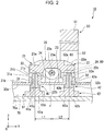
Fig. 2 is a sectional view showing the push-pull switch device of the first embodiment; -
Fig. 3 is a sectional view showing the push-pull switch device of the first embodiment; -
Fig. 4 is a sectional view showing the push-pull switch device of the first embodiment; -
Fig. 5 is a sectional view showing a push-pull switch device of a second embodiment; -
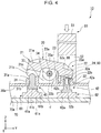
Fig. 6 is a sectional view showing the push-pull switch device of the second embodiment; and -
Fig. 7 is a sectional view showing the push-pull switch device of the second embodiment. - Push-pull switch devices according to embodiments of the present invention will be described below with reference to the drawings. The scope of the present invention is not limited to the following embodiments, and changes may be made without departing from the technical idea of the present invention. In the following drawings, in order to make each configuration understandable, the scale, number, and so forth in each structure may differ from the scale, number, and so forth in the actual structure.
- In the following description, the positional relationship between parts will be described with reference to the three-dimensional orthogonal coordinate system (XYZ coordinate system) shown in each figure. The Z-axis direction is a first direction in which an operation portion is moved. The Y-axis direction is a direction perpendicular to the Z-axis direction. The X-axis direction is a direction perpendicular to both the Z-axis direction and the Y-axis direction.
- In the following description, the Z-axis direction may be referred to as "vertical direction (first direction)," the Y-axis direction may be referred to as "left-right direction (third direction)," and the X-axis direction may be referred to as "front-back direction (second direction)." The positive side (+Z side) in the Z-axis direction may be referred to as "upper side," and the negative side (-Z side) in the Z-axis direction may be referred to as "lower side." The positive side (+Y side) in the Y-axis direction may be referred to as "right side," and the negative side (-Y side) in the Y-axis direction may be referred to as "left side." The vertical direction, left-right direction, front-back direction, upper side, lower side, right side, and left side are merely terms for describing the positional relationship between parts, and do not limit the positional relationship between the actual parts and the use aspect and posture of the actual push-pull switch device.
-
Fig. 1 is a perspective view showing a push-pull switch device 10 of this embodiment.Fig. 2 is a sectional view taken along line II-II ofFig. 1 .Fig. 3 andFig. 4 are sectional views showing the same section asFig. 2 . InFig. 3 andFig. 4 , the state of the push-pull switch device 10 differs from the state of the push-pull switch device 10 shown inFig. 1 andFig. 2 . - The push-
pull switch device 10 of this embodiment includes, as shown in inFig. 1 andFig. 2 , anoperation portion 50, a supportingmember 30, amovable portion 20, aboard 70, afirst switch 61 and asecond switch 62, a first pressingmember 41, and a second pressingmember 42. - The
operation portion 50 is moved in the vertical direction by an operator. Themovable portion 20 moves with the movement in the vertical direction of theoperation portion 50. The supportingmember 30 movably supports themovable portion 20. Thefirst switch 61 and thesecond switch 62 are attached to theboard 70. Thefirst switch 61 and thesecond switch 62 are activated by the movement of themovable portion 20. Thefirst switch 61 and thesecond switch 62 are activated by being pushed via the first pressingmember 41 and the second pressingmember 42 by themovable portion 20. - The push-
pull switch device 10 is switched in response to the operation of theoperation portion 50 between three states: a neutral state, a first state, and a second state. The neutral state is a state in which neither thefirst switch 61 nor thesecond switch 62 are activated. The first state is a state in which thefirst switch 61 is activated. The second state is a state in which thesecond switch 62 is activated.Fig. 1 andFig. 2 show the neutral state.Fig. 3 shows the first state.Fig. 4 shows the second state. - In this specification, "the movable portion moves" includes that the position of at least part of the movable portion changes. That is, in this specification, "the movable portion moves" includes that the movable portion rotates about an axis, moves linearly along a direction, moves in a curve, or performs a movement that combines these movements. For example, in this embodiment, the
movable portion 20 rotates about a central axis (predetermined axis) J. The central axis J is a virtual axis parallel to the front-back direction (X-axis direction). - In the following description, in relation to an object, the side nearer to the central axis J in the left-right direction may be referred to as "inner side in the left-right direction," and the side farther from the central axis J in the left-right direction may be referred to as "outer side in the left-right direction." In relation to an object, the side nearer to the center of the
movable portion 20 in the front-back direction may be referred to as "inner side in the front-back direction," and the side farther from the center of themovable portion 20 in the front-back direction may be referred to as "outer side in the front-back direction." - The
operation portion 50 is held so as to be movable in the vertical direction relative to an apparatus on which the push-pull switch device 10 is mounted. The movement in the left-right direction of theoperation portion 50 is restricted. Theoperation portion 50 extends in the vertical direction. Theoperation portion 50 has amain body portion 51 and a pair of connectingplate portions 52. Themain body portion 51 has, for example, a vertically long rectangular parallelepiped shape. The pair of connectingplate portions 52 extend, as shown inFig. 1 , downward from both ends in the front-back direction of the lower end of themain body portion 51. The connectingplate portions 52 have a plate-like shape extending in a plane (YZ plane) perpendicular to the front-back direction. Holdingholes 52a penetrating the connectingplate portions 52 in the front-back direction are formed in the lower parts of the connectingplate portions 52. The holdingholes 52a are elongate holes extending in the left-right direction. - The supporting
member 30 has, as shown inFig. 2 , abase portion 30a, afirst guide portion 31, asecond guide portion 32, and a pair of supportingplate portions 33. Thebase portion 30a extends in a plane (XY plane) perpendicular to the vertical direction. Thefirst guide portion 31 and thesecond guide portion 32 protrude upward from the upper surface of thebase portion 30a. Thefirst guide portion 31 and thesecond guide portion 32 are spaced in the left-right direction. Thefirst guide portion 31 is disposed on the left side (-Y side) of the central axis J. Thesecond guide portion 32 is disposed on the right side (+Y side) of the central axis J. - The upper surface of the
first guide portion 31 is a flat firstinclined surface 31a that inclines downward from the inner side in the left-right direction (+Y side) to the outer side in the left-right direction (-Y side). Afirst guide hole 31b that vertically penetrates thefirst guide portion 31 and thebase portion 30a is formed in thefirst guide portion 31. The cross-sectional shape of thefirst guide hole 31b is, for example, circular. - The upper surface of the
second guide portion 32 is a flat secondinclined surface 32a that inclines downward from the inner side in the left-right direction (-Y side) to the outer side in the left-right direction (+Y side). Asecond guide hole 32b that vertically penetrates thesecond guide portion 32 and thebase portion 30a is formed in thesecond guide portion 32. The cross-sectional shape of thesecond guide hole 32b is, for example, circular. - The supporting
plate portions 33 extend, as shown inFig. 1 andFig. 2 , upward from the upper surface of thebase portion 30a. The supportingplate portions 33 has a plate-like shape extending in a plane (YZ plane) perpendicular to the front-back direction. The supportingplate portions 33 are located between thefirst guide portion 31 and thesecond guide portion 32 in the left-right direction. The pair of supportingplate portions 33 are spaced in the front-back direction. The pair of supportingplate portions 33 each have ashaft portion 34 protruding toward the other supporting plate portion 33 (protruding to the inner side in the front-back direction). Theshaft portions 34 of the pair of supportingplate portions 33 both have a cylindrical shape centered on the central axis J. - The
movable portion 20 has abase portion 20a, afirst portion 21, asecond portion 22, a pair ofcentral plate portions 23, and a pair of pins 24. Thebase portion 20a extends in the left-right direction. Thefirst portion 21 is provided at the left side (-Y side) end of thebase portion 20a. Thefirst portion 21 has a firstmain body portion 21a and a pair offirst plate portions 21b. The firstmain body portion 21a has a substantially rectangular parallelepiped shape. As shown inFig. 2 , afirst contact surface 21c that is the lower surface of the firstmain body portion 21a faces the firstinclined surface 31a of thefirst guide portion 31 in the vertical direction. The pair offirst plate portions 21b extend, as shown inFig. 1 , downward from both ends in the front-back direction of the firstmain body portion 21a. Thefirst plate portions 21b have a plate-like shape extending in a plane (YZ plane) perpendicular to the front-back direction. - The
second portion 22 is provided at the right side (+Y side) end of thebase portion 20a. Thesecond portion 22 has a secondmain body portion 22a and a pair ofsecond plate portions 22b. The secondmain body portion 22a has a substantially rectangular parallelepiped shape. As shown inFig. 2 , asecond contact surface 22c that is the lower surface of the secondmain body portion 22a faces the secondinclined surface 32a of thesecond guide portion 32 in the vertical direction. The pair ofsecond plate portions 22b extend downward from both ends in the front-back direction of the secondmain body portion 22a. Thesecond plate portions 22b have a plate-like shape extending in a plane (YZ plane) perpendicular to the front-back direction. - The pair of
central plate portions 23 extend, as shown inFig. 1 andFig. 2 , downward from both ends in the front-back direction of the center in the left-right direction of thebase portion 20a. Thecentral plate portions 23 has a plate-like shape extending in a plane (YZ plane) perpendicular to the front-back direction.Shaft holes 23a penetrating thecentral plate portions 23 in the front-back direction are formed in the pair ofcentral plate portions 23. The cross-sectional shape of theshaft holes 23a is, for example, circular, and the central axis J passes through the centers of theshaft holes 23a. Theshaft portions 34 of the pair of supportingplate portions 33 are inserted and fitted into the shaft holes 23a of the pair ofcentral plate portions 23 from the outer side in the front-back direction. Themovable portion 20 is thereby supported by the supportingmember 30 rotatably about the central axis J. - The pair of pins 24 protrude from the pair of
second plate portions 22b to the outer side in the front-back direction. The pins 24 are substantially cylindrical in shape. The pins 24 are inserted into the holdingholes 52a of the connectingplate portions 52 from the inner side in the front-back direction. Both ends in the vertical direction of the pins 24 are in contact, for example, with the inner surfaces in the vertical direction of the holdingholes 52a. In this embodiment, the pins 24 are disposed at substantially the same position as the center of thesecond switch 62 and the center of theoperation portion 50 in the left-right direction. - The holding holes 52a and the pins 24 form a connecting
mechanism 80 that converts the movement of theoperation portion 50 and transmits it to themovable portion 20. In this embodiment, themovable portion 20 is rotatably connected to theoperation portion 50 by the connectingmechanism 80. The connectingmechanism 80 is disposed on thesecond switch 62 side (right side, +Y side) of the central axis J in the left-right direction. In this embodiment, the connectingmechanism 80 is disposed at substantially the same position as the center of thesecond switch 62 and the center of theoperation portion 50 in the left-right direction. Themovable portion 20 is, for example, a single member and is manufactured by injection molding or the like. - The
board 70 is disposed on the lower side of the supportingmember 30. Theboard 70 has a plate-like shape extending in a plane (XY plane) perpendicular to the vertical direction. Theboard 70 is fixed, for example, to the supportingmember 30. Thefirst switch 61 and thesecond switch 62 are attached to theupper surface 70a of theboard 70. - The
first switch 61 and thesecond switch 62 are, for example, tactile switches. Thefirst switch 61 is disposed so as to face thefirst guide hole 31b in the vertical direction. Thefirst switch 61 has afirst housing portion 61a and afirst button portion 61b. Thefirst housing portion 61a has a hollow box shape that is square in plan view. Thefirst button portion 61b has a cylindrical shape. Thefirst button portion 61b is attached to thefirst housing portion 61a movably in the vertical direction. - In a state in which the
first switch 61 is not activated shown inFig. 2 , thefirst button portion 61b protrudes upward from thefirst housing portion 61a. Thefirst switch 61 is activated when thefirst button portion 61b is pushed into the inside of thefirst housing portion 61a as shown inFig. 3 .
Thesecond switch 62 is disposed so as to face thesecond guide hole 32b in the vertical direction. Thesecond switch 62 has asecond housing portion 62a and asecond button portion 62b. Thesecond housing portion 62a has a hollow box shape that is square in plan view. Thesecond button portion 62b has a cylindrical shape. Thesecond button portion 62b is attached to thesecond housing portion 62a movably in the vertical direction. - In a state in which the
second switch 62 is not activated shown inFig. 2 , thesecond button portion 62b protrudes upward from thesecond housing portion 62a. Thesecond switch 62 is activated when thesecond button portion 62b is pushed into the inside of thesecond housing portion 62a as shown inFig. 4 . - In
Fig. 2 to Fig. 4 , thefirst switch 61 and thesecond switch 62 are schematically shown as an integral member. - The first pressing
member 41 is disposed on the upper surface of thefirst button portion 61b of thefirst switch 61. The first pressingmember 41 has afirst slide portion 41a and afirst flange portion 41b. Thefirst slide portion 41a has a cylindrical shape extending in the vertical direction. Thefirst slide portion 41a is fitted in thefirst guide hole 31b. Thefirst slide portion 41a is movable in thefirst guide hole 31b in the vertical direction. The upper end of thefirst slide portion 41a faces thefirst contact surface 21c in the vertical direction. The upper end of thefirst slide portion 41a is hemispherical in shape. When thefirst switch 61 is not activated, the upper end of thefirst slide portion 41a is protruding upward from thefirst guide hole 31b. - The
first flange portion 41b extends from the lower end of thefirst slide portion 41a outward in the radial direction of thefirst slide portion 41a. The lower surface of thefirst flange portion 41b is in contact with the upper surface of thefirst button portion 61b. The upper surface of thefirst flange portion 41b is in contact with the lower surface of thebase portion 30a of the supportingmember 30, for example, when thefirst switch 61 is not activated. In this embodiment, themovable portion 20 is indirectly in contact with thefirst switch 61 with the first pressingmember 41 interposed therebetween. - The second pressing
member 42 is disposed on the upper surface of thesecond button portion 62b of thesecond switch 62. The second pressingmember 42 has asecond slide portion 42a and asecond flange portion 42b. Thesecond slide portion 42a has a cylindrical shape extending in the vertical direction. Thesecond slide portion 42a is fitted in thesecond guide hole 32b. Thesecond slide portion 42a is movable in thesecond guide hole 32b in the vertical direction. The upper end of thesecond slide portion 42a faces thesecond contact surface 22c in the vertical direction. The upper end of thesecond slide portion 42a is hemispherical in shape. When thesecond switch 62 is not activated, the upper end of thesecond slide portion 42a is protruding upward from thesecond guide hole 32b. - The
second flange portion 42b extends from the lower end of thesecond slide portion 42a outward in the radial direction of thesecond slide portion 42a. The lower surface of thesecond flange portion 42b is in contact with the upper surface of thesecond button portion 62b. The upper surface of thesecond flange portion 42b is in contact with the lower surface of thebase portion 30a of the supportingmember 30, for example, when thesecond switch 62 is not activated. In this embodiment, themovable portion 20 is indirectly in contact with thesecond switch 62 with the second pressingmember 42 interposed therebetween. - In
Fig. 2 , the distance L1 in the left-right direction between a part of themovable portion 20 that is in contact with thefirst switch 61 and the central axis J and the distance L2 in the left-right direction between the connectingmechanism 80 and the central axis J are, for example, equal. In this embodiment, a part of themovable portion 20 that is in contact with thefirst switch 61 is a part of themovable portion 20 that is indirectly in contact with thefirst switch 61, that is, a part in contact with the upper end of the first pressingmember 41. In this embodiment, the distance L2 in the left-right direction between the connectingmechanism 80 and the central axis J is the distance in the left-right direction between the center of the pins 24 and the central axis J. - In this embodiment, the distance L1 is equal to the distance in the left-right direction between the center in the left-right direction of the
first button portion 61b of thefirst switch 61 and the central axis J. In this embodiment, the distance L2 is equal to the distance in the left-right direction between the center in the left-right direction of thesecond button portion 62b of thesecond switch 62 and the central axis J. - Next, the operation of the push-
pull switch device 10 will be described. Themovable portion 20 performs a first moving operation with the upward movement (the movement in one sense in the first direction) of theoperation portion 50, and performs a second operation different from the first moving operation with the downward movement (the movement in the other sense in the first direction) of theoperation portion 50. The first moving operation differs from the upward movement of theoperation portion 50, and the second moving operation differs from the downward movement of theoperation portion 50. In this embodiment, the first moving operation and the second moving operation are rotational operations in which themovable portion 20 rotates about the central axis J. Thefirst switch 61 is activated by the first moving operation, and thesecond switch 62 is activated by the second moving operation. - In this specification, "the first moving operation and the second moving operation differ from each other" includes that the first moving operation and the second moving operation differ from each other in at least one of the type of movement of the movable portion, the direction in which the movable portion moves, the distance that the movable portion moves, and so forth. For example, when the first moving operation and the second moving operation are moving operations in which the movable portion moves in the same sense, but differ in the distance that the movable portion moves, the first moving operation and the second moving operation differ from each other.
- In this specification, "the first moving operation and the second moving operation differ from each other" includes that, when the movement of the operation portion causes the movable portion to perform moving operation, at least part of the movable portion moves in a direction different from the moving direction of the operation portion.
- As shown in
Fig. 2 , in the neutral state, thefirst contact surface 21c and thesecond contact surface 22c are perpendicular to the vertical direction. Thefirst contact surface 21c is in contact with the upper end of the first pressingmember 41. Thesecond contact surface 22c is in contact with the upper end of the second pressingmember 42. When theoperation portion 50 is operated and the first moving operation of themovable portion 20 is performed, the push-pull switch device 10 is brought from the neutral state into the first state. When theoperation portion 50 is operated and the second moving operation of themovable portion 20 is performed, the push-pull switch device 10 is brought from the neutral state into the second state. - In this embodiment, the first moving operation is an operation in which, as shown in
Fig. 3 , themovable portion 20 rotates about the central axis J counterclockwise in the front view (as viewed from the +X side to the -X side). Theoperation portion 50 is pulled upward, and an upward force is thereby applied through the connectingmechanism 80 to thesecond portion 22 of themovable portion 20. More specifically, the lower inner surfaces of the holdingholes 52a push up the pins 24 from below, and an upward force is thereby applied to thesecond portion 22. Themovable portion 20 thereby rotates about the central axis J counterclockwise, and the first moving operation is performed. - When the first moving operation is performed, the
second portion 22 moves upward, and thefirst portion 21 moves downward. The first pressingmember 41 is thereby pushed downward by thefirst contact surface 21c of thefirst portion 21. Then, thefirst button portion 61b of thefirst switch 61 is pushed downward by the first pressingmember 41, and thefirst switch 61 is activated. The push-pull switch device 10 is thereby brought into the first state. - In the first state, the
first contact surface 21c and the firstinclined surface 31a are, for example, parallel to and in contact with each other. In the first state, thesecond switch 62 is not activated. In the first state, thesecond contact surface 22c is upwardly separated from the second pressingmember 42. - In this embodiment, the second moving operation is an operation in which, as shown in
Fig. 4 , themovable portion 20 rotates about the central axis J clockwise in the front view (as viewed from the +X side to the -X side). Theoperation portion 50 is pushed downward, and a downward force is thereby applied through the connectingmechanism 80 to thesecond portion 22 of themovable portion 20. More specifically, the upper inner surfaces of the holdingholes 52a push down the pins 24 from above, and a downward force is thereby applied to thesecond portion 22. Themovable portion 20 thereby rotates about the central axis J clockwise, and the second moving operation is performed. - When the second moving operation is performed, the
first portion 21 moves upward, and thesecond portion 22 moves downward. The second pressingmember 42 is thereby pushed downward by thesecond contact surface 22c of thesecond portion 22. Then, thesecond button portion 62b of thesecond switch 62 is pushed downward by the second pressingmember 42, and thesecond switch 62 is activated. The push-pull switch device 10 is thereby brought into the second state. - In the second state, the
second contact surface 22c and the secondinclined surface 32a are, for example, parallel to and in contact with each other. In the second state, thefirst switch 61 is not activated. In the second state, thefirst contact surface 21c is upwardly separated from the first pressingmember 41. - In this way, the push-
pull switch device 10 is switched among three states. Therefore, in an apparatus on which the push-pull switch device 10 is mounted, for example, various functions can be switched. - Since the
movable portion 20 rotates in the first moving operation and the second moving operation, the position in the left-right direction of the pins 24 changes. Since the holdingholes 52a into which the pins 24 are inserted are elongate holes extending in the left-right direction, the pins 24 are allowed to move in the left-right direction. - For example, suppose that the operating states of two switches are switched by just using the movement in the vertical direction of an operation portion directly. In this case, the operation portion can basically perform only a monotonic operation in which the operation portion simply moves toward or away from one surface of a board. Therefore, it is difficult to individually switch the operating states of two switches attached to one surface of a board. Therefore, in this case, in order to switch the operating states of two switches, it is necessary, for example, as described in Japanese Examined Utility Model Registration Application Publication No.
62-13303 - In contrast, this embodiment is provided with the
movable portion 20 that performs the first moving operation and the second moving operation different from each other in response respectively to the upward movement and the downward movement of theoperation portion 50. The first moving operation differs from the upward movement of theoperation portion 50, and the second moving operation differs from the downward movement of theoperation portion 50. In other words, this embodiment is provided with themovable portion 20 to which the movement in the vertical direction of theoperation portion 50 is converted into two different moving operations and transmitted. This enables approaches to one surface (theupper surface 70a) of theboard 70 that differ between the first moving operation and the second moving operation of themovable portion 20. Therefore, by interposing themovable portion 20, it is made possible that the operating states of thefirst switch 61 and thesecond switch 62 attached to one surface (theupper surface 70a) of theboard 70 are individually switched by the movement in the vertical direction of theoperation portion 50. - As described above, in this embodiment, both the
first switch 61 and thesecond switch 62 can be attached to one surface (theupper surface 70a) of theboard 70, and the time required for assembling the push-pull switch device 10 can be reduced. Therefore, a push-pull switch device 10 having excellent assemblability can be obtained. Since thefirst switch 61 and thesecond switch 62 can be attached to one surface of theboard 70, the other surface (the lower surface) of theboard 70 can be effectively utilized. - In this embodiment, the first moving operation and the second moving operation are rotational operations. Therefore, by rotatably supporting the
movable portion 20 at one point (the central axis J), the movement in the vertical direction of theoperation portion 50 can be easily converted into the first moving operation and the second moving operation of themovable portion 20. Therefore, the structure of the push-pull switch device 10 can be simplified. - In this embodiment, the central axis J about which the
movable portion 20 rotates is located between thefirst switch 61 and thesecond switch 62 in the left-right direction. Therefore, the sense in which themovable portion 20 rotates in the first moving operation and the sense in which themovable portion 20 rotates in the second moving operation can be opposite to each other, and the moving operations can be used as operations to activate the switches. Therefore, each switch can be easily reliably activated with a simple structure. - In this embodiment, the connecting
mechanism 80 connecting themovable portion 20 and theoperation portion 50 is disposed on thesecond switch 62 side of the central axis J. Therefore, the movement in the vertical direction of theoperation portion 50 can be easily converted into rotational operation of themovable portion 20 through the connectingmechanism 80, and the sense in which themovable portion 20 rotates in the first moving operation and the sense in which themovable portion 20 rotates in the second moving operation can be opposite to each other. - In this embodiment, the connecting
mechanism 80 includes holdingholes 52a provided in theoperation portion 50, and pins 24 provided on themovable portion 20 and inserted into the holdingholes 52a. Therefore, the configuration of the connectingmechanism 80 can be simplified, and the manufacturing cost of the push-pull switch device 10 can be reduced. When, as in this embodiment, the pins 24 are provided integrally with themovable portion 20, an increase in the number of parts of the push-pull switch device 10 can be suppressed, and an increase in the man-hour for the assembly of the push-pull switch device 10 can be suppressed. - In this embodiment, the connecting
mechanism 80 is disposed at substantially the same position as the center of thesecond switch 62 and the center of theoperation portion 50 in the left-right direction. Therefore, when moving theoperation portion 50 downward to cause themovable portion 20 to perform the second moving operation, the operating force applied to theoperation portion 50 is easily transmitted to thesecond switch 62. Therefore, when causing themovable portion 20 to perform the second moving operation, the operating force applied to theoperation portion 50 can be reduced. - Since, in the first state, the
first contact surface 21c and the firstinclined surface 31a come into contact with each other, themovable portion 20 is prevented from rotating counterclockwise beyond the position shown inFig. 3 . Since, in the second state, thesecond contact surface 22c and the secondinclined surface 32a come into contact with each other, themovable portion 20 is prevented from rotating clockwise beyond the position shown inFig. 4 . Therefore, thefirst button portion 61b of thefirst switch 61 and thesecond button portion 62b of thesecond switch 62 can be prevented from being pushed downward more than necessary, and thefirst switch 61 and thesecond switch 62 can be prevented from being damaged. - Since the
first contact surface 21c and the firstinclined surface 31a are parallel to and in contact with each other in the first state, the rotation of themovable portion 20 can be stably restricted. Since thesecond contact surface 22c and the secondinclined surface 32a are parallel to and in contact with each other in the second state, the rotation of themovable portion 20 can be stably restricted. - The present invention is not limited to the above-described embodiment, and other configurations can be used. The same reference signs will be used to designate the same components as those in the above-described embodiment, and the description thereof may be omitted.
- The distance L1 in the left-right direction between a part of the
movable portion 20 that is in contact with thefirst switch 61 and the central axis J and the distance L2 in the left-right direction between the connectingmechanism 80 and the central axis J may differ from each other. For example, the distance L2 may be greater than the distance L1. - For example, when moving the
operation portion 50 downward to cause themovable portion 20 to perform the second moving operation, the weight of theoperation portion 50 itself can be utilized, and therefore thesecond switch 62 is easily activated if the force applied to theoperation portion 50 is relatively small. On the other hand, when moving theoperation portion 50 upward to cause themovable portion 20 to perform the first moving operation, the force lifting theoperation portion 50 itself is required in addition to the force required to activate thefirst switch 61. Therefore, the operating force applied to theoperation portion 50 needs to be relatively large. - In contrast, in the above-described configuration, since the distance L2 is greater than the distance L1, the force acting on the
first switch 61 when moving theoperation portion 50 upward can be increased by the principle of leverage. Therefore, the operating force required to move theoperation portion 50 upward to cause themovable portion 20 to perform the first moving operation can be reduced. Therefore, both when causing themovable portion 20 to perform the first moving operation and when causing themovable portion 20 to perform the second moving operation, the operating force applied to theoperation portion 50 can be relatively small. As a result, the operability of the push-pull switch device 10 can be improved, and the convenience for the operator can be improved. This is very effective particularly when theoperation portion 50 is relatively heavy in weight. - As described above, since the central axis J about which the
movable portion 20 rotates is between thefirst switch 61 and thesecond switch 62, the distance L1 and the distance L2 can be adjusted to improve the operability of the push-pull switch device 10. - The holding
holes 52a may be bottomed holes that do not penetrate the connectingplate portions 52. Holding holes forming part of the connecting mechanism may be provided in themovable portion 20, and pins forming part of the connecting mechanism may be provided on theoperation portion 50. - The shaft holes 23a of the
movable portion 20 may be bottomed holes that do not penetrate thecentral plate portions 23. Shaft holes may be provided in the supportingplate portions 33 of the supportingmember 30, and shaft portions to be fitted in the shaft holes may be provided on thecentral plate portions 23 of themovable portion 20. -
Fig. 5 to Fig. 7 are sectional views of a push-pull switch device 110 according to this embodiment as viewed along the front-back direction (as viewed from the +X side to the -X side).Fig. 5 shows the push-pull switch device 110 in the neutral state.Fig. 6 shows the push-pull switch device 110 in the first state.Fig. 7 shows the push-pull switch device 110 in the second state. - The push-
pull switch device 110 includes, as shown inFig. 5 , anoperation portion 150, aguide member 130, amovable portion 120, aboard 70, afirst switch 161, and asecond switch 162. - In the
operation portion 150, connectingplate portions 152 are provided with pins 153 protruding in the front-back direction. The pins 153 are, for example, cylindrical in shape. In other respects, the configuration of theoperation portion 150 is the same as the configuration of theoperation portion 50 of the first embodiment. - The
guide member 130 has a plate-like shape extending in a plane (XY plane) perpendicular to the vertical direction. Theguide member 130 is disposed above theboard 70. A through-hole 130a penetrating theguide member 130 in the vertical direction is formed in theguide member 130. Theoperation portion 150 extends through the inside of the through-hole 130a in the vertical direction. - The
movable portion 120 is disposed between theguide member 130 and theboard 70 in the vertical direction. Themovable portion 120 is a member having a trapezoidal cross-sectional shape (YZ cross-sectional shape). In the left-right direction, the length of the lower side of the cross-sectional shape of themovable portion 120 is less than the length of the upper side of the cross-sectional shape of themovable portion 120. Theupper surface 120a of themovable portion 120 is in contact with the lower surface of theguide member 130. Thelower surface 120b of themovable portion 120 is in contact with theupper surface 70a of theboard 70. Themovable portion 120 is disposed slidably in the left-right direction relative to the lower surface of theguide member 130 and theupper surface 70a of theboard 70. - A
first contact surface 121 that is the left side (-Y side) surface of themovable portion 120 is an inclined surface that inclines downwardly to the right side (+Y side). Asecond contact surface 122 that is the right side (+Y side) surface of themovable portion 120 is an inclined surface that inclines downwardly to the left side (-Y side). - A holding
hole 123 that penetrates themovable portion 120 in the front-back direction is formed in themovable portion 120. The holdinghole 123 extends in a direction inclined to the vertical direction. InFig. 5 , the holdinghole 123 inclines downwardly to the right side (+Y side). A pin 153 is inserted into the holdinghole 123. - The holding
hole 123 and the pin 153 form a connectingmechanism 180. In this embodiment, the connectingmechanism 180 is disposed between thefirst switch 161 and thesecond switch 162 in the left-right direction. - The
first switch 161 and thesecond switch 162 are attached to theupper surface 70a of theboard 70. Thefirst switch 161 and thesecond switch 162 are switches that are activated by being pushed from above. Thefirst switch 161 and thesecond switch 162 are each, for example, a switch in which a moving contact is provided in a cover made of rubber. - Next, the operation of the push-
pull switch device 110 will be described. Themovable portion 120 performs a first moving operation with the upward movement (the movement in one sense in the first direction) of theoperation portion 150, and performs a second operation different from the first moving operation with the downward movement (the movement in the other sense in the first direction) of theoperation portion 150. In this embodiment, the first moving operation and the second moving operation are moving operations in which themovable portion 120 moves linearly along the left-right direction. Thefirst switch 161 is activated by the first moving operation, and thesecond switch 162 is activated by the second moving operation. - In this embodiment, the first moving operation is an operation in which, as shown in
Fig. 6 , themovable portion 120 moves to the left (in the -Y sense). Theoperation portion 150 is pushed downward, and the pin 153 thereby pushes the inner surface of the holdinghole 123 downward. The pin 153 thereby moves relative to the holdinghole 123 to the lower right. Since the movement in the left-right direction of theoperation portion 150 is restricted, the relative movement between the pin 153 and the holdinghole 123 causes themovable portion 120 to move in the left-right direction (to the left). When the first moving operation is performed, thefirst switch 161 is pushed downward by thefirst contact surface 121, and thefirst switch 161 is activated. The push-pull switch device 110 is thereby brought into the first state. - In this embodiment, the second moving operation is an operation in which, as shown in
Fig. 7 , themovable portion 120 moves to the right (in the +Y sense). Theoperation portion 150 is pulled upward, and the pin 153 thereby pushes the inner surface of the holdinghole 123 upward. The pin 153 thereby moves relative to the holdinghole 123 to the upper left, and themovable portion 120 moves to the right. When the second moving operation is performed, thesecond switch 162 is pushed downward by thesecond contact surface 122, and thesecond switch 162 is activated. The push-pull switch device 110 is thereby brought into the second state. - In this embodiment, the operating states of the switches can be switched by the linear moving operation of the
movable portion 120. Therefore, by making the moving direction of themovable portion 120 parallel to theupper surface 70a of theboard 70 on which the switches are disposed, the whole push-pull switch device 110 can be reduced in size in the vertical direction. - In the above-described embodiments, the first switch and the second switch are not particularly limited. The first switch and the second switch may each be, for example, a push switch having a metal reversal spring. Sensors such as magnetic sensors and light sensors may be used as the first switch and the second switch. In this case, for example, sensors serving as the switches may be activated when the movement of the movable portion is detected by the sensors.
- Apparatuses on which the push-pull switch devices of the above-described embodiments are mounted are not particularly limited. For example, the push-pull switch devices of the embodiments are mounted on an apparatus provided in a vehicle.
- The above-described configurations may be appropriately combined to the extent that they do not conflict with one another.
Claims (7)
- A push-pull switch device (10, 110) comprising:an operation portion (50, 150);a movable portion (20, 120) that moves with the movement in a first direction of the operation portion (50, 150);a first switch (61, 161) and a second switch (62, 162) that are activated by the movement of the movable portion (20, 120); anda board (70) to one surface of which the first switch (61, 161) and the second switch (62, 162) are attached,wherein the movable portion (20, 120) performs a first moving operation with the movement of the operation portion (50, 150) in one sense in the first direction, and performs a second moving operation different from the first moving operation with the movement of the operation portion (50, 150) in the other sense in the first direction,wherein the first moving operation differs from the movement of the operation portion (50, 150) in one sense in the first direction,wherein the second moving operation differs from the movement of the operation portion (50, 150) in the other sense in the first direction,wherein the first switch (61, 161) is activated by the first moving operation of the movable portion (20, 120), andwherein the second switch (62, 162) is activated by the second moving operation of the movable portion (20, 120).
- The push-pull switch device (10) according to Claim 1, wherein the first moving operation and the second moving operation are rotational operations in which the movable portion (20) rotates about a predetermined axis (J).
- The push-pull switch device (10) according to Claim 2, wherein the predetermined axis (J) is parallel to a second direction perpendicular to the first direction, and is located between the first switch (61) and the second switch (62) in a third direction perpendicular to both the first direction and the second direction.
- The push-pull switch device (10) according to Claim 3,
wherein the movable portion (20) is rotatably connected to the operation portion (50) by a connecting mechanism (80), and
wherein the connecting mechanism (80) is disposed on the second switch (62) side of the predetermined axis (J) in the third direction. - The push-pull switch device (10) according to Claim 4,
wherein the distance in the third direction between the connecting mechanism (80) and the predetermined axis (J) is greater than the distance in the third direction between a part of the movable portion (20) that is in contact with the first switch (61) and the predetermined axis (J). - The push-pull switch device (10) according to Claim 4 or 5,
wherein the connecting mechanism (80) is formed by a holding hole (52a) provided in one of the operation portion (50) and the movable portion (20), and a pin (24) provided on the other of the operation portion (50) and the movable portion (20) and inserted into the holding hole (52a). - The push-pull switch device (110) according to Claim 1, wherein the first moving operation and the second moving operation are moving operations in which the movable portion (120) moves linearly.
Applications Claiming Priority (1)
| Application Number | Priority Date | Filing Date | Title |
|---|---|---|---|
| JP2016076620A JP6652875B2 (en) | 2016-04-06 | 2016-04-06 | Push-pull switch device |
Publications (2)
| Publication Number | Publication Date |
|---|---|
| EP3229248A1 true EP3229248A1 (en) | 2017-10-11 |
| EP3229248B1 EP3229248B1 (en) | 2018-10-24 |
Family
ID=58489583
Family Applications (1)
| Application Number | Title | Priority Date | Filing Date |
|---|---|---|---|
| EP17164913.0A Active EP3229248B1 (en) | 2016-04-06 | 2017-04-05 | Push-pull switch device |
Country Status (2)
| Country | Link |
|---|---|
| EP (1) | EP3229248B1 (en) |
| JP (1) | JP6652875B2 (en) |
Families Citing this family (1)
| Publication number | Priority date | Publication date | Assignee | Title |
|---|---|---|---|---|
| CN112840425A (en) * | 2018-10-16 | 2021-05-25 | 松下知识产权经营株式会社 | input device |
Citations (8)
| Publication number | Priority date | Publication date | Assignee | Title |
|---|---|---|---|---|
| US3024333A (en) * | 1959-11-16 | 1962-03-06 | Square D Co | Electrical switch |
| US3308260A (en) * | 1966-01-28 | 1967-03-07 | Cutler Hammer Inc | Electric switches |
| US4101749A (en) * | 1976-12-15 | 1978-07-18 | Cutler-Hammer, Inc. | Electrical attachment of indicating lamp to terminals in electric switches |
| US4504712A (en) * | 1983-11-07 | 1985-03-12 | Carlingswitch, Inc. | Plunger switch with pivoted actuator |
| JPS6213303A (en) | 1985-07-12 | 1987-01-22 | 株式会社日立製作所 | Slip casting molding method |
| DE4029690A1 (en) * | 1990-08-04 | 1992-02-06 | Marquardt Gmbh | Actuator for main switch - has connecting rod coupled between actuator rocker and remote switch unit |
| US5426274A (en) * | 1993-01-19 | 1995-06-20 | Preh-Werke Gmbh & Co. Kg | Push button switch |
| US6756553B1 (en) * | 2003-06-30 | 2004-06-29 | Kojima Press Industry Co., Ltd. | Switch unit |
Family Cites Families (6)
| Publication number | Priority date | Publication date | Assignee | Title |
|---|---|---|---|---|
| JP2542376Y2 (en) * | 1991-12-05 | 1997-07-23 | 小島プレス工業株式会社 | Switch device |
| JP3896616B2 (en) * | 1997-01-10 | 2007-03-22 | 松下電器産業株式会社 | Push-pull switch |
| JP3877662B2 (en) * | 2002-08-30 | 2007-02-07 | 株式会社クボタ | Work vehicle vacancy detection device |
| DE10341101B4 (en) * | 2003-09-05 | 2006-10-12 | Trw Automotive Electronics & Components Gmbh & Co. Kg | toggle switch |
| JP4375243B2 (en) * | 2005-02-07 | 2009-12-02 | 住友電装株式会社 | Seesaw switch |
| JP2015111542A (en) * | 2013-11-05 | 2015-06-18 | 株式会社東海理化電機製作所 | Input device |
-
2016
- 2016-04-06 JP JP2016076620A patent/JP6652875B2/en active Active
-
2017
- 2017-04-05 EP EP17164913.0A patent/EP3229248B1/en active Active
Patent Citations (8)
| Publication number | Priority date | Publication date | Assignee | Title |
|---|---|---|---|---|
| US3024333A (en) * | 1959-11-16 | 1962-03-06 | Square D Co | Electrical switch |
| US3308260A (en) * | 1966-01-28 | 1967-03-07 | Cutler Hammer Inc | Electric switches |
| US4101749A (en) * | 1976-12-15 | 1978-07-18 | Cutler-Hammer, Inc. | Electrical attachment of indicating lamp to terminals in electric switches |
| US4504712A (en) * | 1983-11-07 | 1985-03-12 | Carlingswitch, Inc. | Plunger switch with pivoted actuator |
| JPS6213303A (en) | 1985-07-12 | 1987-01-22 | 株式会社日立製作所 | Slip casting molding method |
| DE4029690A1 (en) * | 1990-08-04 | 1992-02-06 | Marquardt Gmbh | Actuator for main switch - has connecting rod coupled between actuator rocker and remote switch unit |
| US5426274A (en) * | 1993-01-19 | 1995-06-20 | Preh-Werke Gmbh & Co. Kg | Push button switch |
| US6756553B1 (en) * | 2003-06-30 | 2004-06-29 | Kojima Press Industry Co., Ltd. | Switch unit |
Also Published As
| Publication number | Publication date |
|---|---|
| JP6652875B2 (en) | 2020-02-26 |
| JP2017188326A (en) | 2017-10-12 |
| EP3229248B1 (en) | 2018-10-24 |
Similar Documents
| Publication | Publication Date | Title |
|---|---|---|
| EP3056768A1 (en) | Shift device | |
| KR20110084090A (en) | Input device | |
| US10372153B2 (en) | Lever device | |
| EP3546254A1 (en) | Automated guided vehicle | |
| KR101792390B1 (en) | Precise spatial mover | |
| CN115701643A (en) | Multi-directional input device | |
| US20140374225A1 (en) | Pressure and Rotationally Actuated Control Element for a Motor Vehicle | |
| JP6049079B2 (en) | Lever switch | |
| EP3229248B1 (en) | Push-pull switch device | |
| JP2015027661A (en) | Tactile type solenoid and attachment structure of the same | |
| JP6267494B2 (en) | Shift lever device | |
| US20220293365A1 (en) | Switching device | |
| US20150107971A1 (en) | Switching device | |
| US20050056530A1 (en) | Multi-way electric switch having operator control supported by two orthogonal parallel linkages coupled via intermediate part | |
| WO2016136002A1 (en) | Switch | |
| JP2016187994A (en) | Shifter | |
| JP6648651B2 (en) | Electromagnetic relay | |
| US9720436B2 (en) | Operation input device | |
| JP2023111813A (en) | Multi-directional operation switch device | |
| EP3431317B1 (en) | Shift device | |
| US9589742B2 (en) | Pressing operation device | |
| US20150084890A1 (en) | Input device | |
| US6965084B2 (en) | Multidirectional input device | |
| JP3177137U (en) | Input device | |
| US10054975B2 (en) | Remote control device movable structure |
Legal Events
| Date | Code | Title | Description |
|---|---|---|---|
| PUAI | Public reference made under article 153(3) epc to a published international application that has entered the european phase |
Free format text: ORIGINAL CODE: 0009012 |
|
| STAA | Information on the status of an ep patent application or granted ep patent |
Free format text: STATUS: THE APPLICATION HAS BEEN PUBLISHED |
|
| AK | Designated contracting states |
Kind code of ref document: A1 Designated state(s): AL AT BE BG CH CY CZ DE DK EE ES FI FR GB GR HR HU IE IS IT LI LT LU LV MC MK MT NL NO PL PT RO RS SE SI SK SM TR |
|
| AX | Request for extension of the european patent |
Extension state: BA ME |
|
| STAA | Information on the status of an ep patent application or granted ep patent |
Free format text: STATUS: REQUEST FOR EXAMINATION WAS MADE |
|
| GRAP | Despatch of communication of intention to grant a patent |
Free format text: ORIGINAL CODE: EPIDOSNIGR1 |
|
| STAA | Information on the status of an ep patent application or granted ep patent |
Free format text: STATUS: GRANT OF PATENT IS INTENDED |
|
| 17P | Request for examination filed |
Effective date: 20180329 |
|
| RBV | Designated contracting states (corrected) |
Designated state(s): AL AT BE BG CH CY CZ DE DK EE ES FI FR GB GR HR HU IE IS IT LI LT LU LV MC MK MT NL NO PL PT RO RS SE SI SK SM TR |
|
| INTG | Intention to grant announced |
Effective date: 20180508 |
|
| GRAS | Grant fee paid |
Free format text: ORIGINAL CODE: EPIDOSNIGR3 |
|
| GRAA | (expected) grant |
Free format text: ORIGINAL CODE: 0009210 |
|
| STAA | Information on the status of an ep patent application or granted ep patent |
Free format text: STATUS: THE PATENT HAS BEEN GRANTED |
|
| AK | Designated contracting states |
Kind code of ref document: B1 Designated state(s): AL AT BE BG CH CY CZ DE DK EE ES FI FR GB GR HR HU IE IS IT LI LT LU LV MC MK MT NL NO PL PT RO RS SE SI SK SM TR |
|
| REG | Reference to a national code |
Ref country code: CH Ref legal event code: EP |
|
| REG | Reference to a national code |
Ref country code: IE Ref legal event code: FG4D |
|
| REG | Reference to a national code |
Ref country code: AT Ref legal event code: REF Ref document number: 1057666 Country of ref document: AT Kind code of ref document: T Effective date: 20181115 |
|
| REG | Reference to a national code |
Ref country code: DE Ref legal event code: R096 Ref document number: 602017000679 Country of ref document: DE |
|
| REG | Reference to a national code |
Ref country code: DE Ref legal event code: R082 Ref document number: 602017000679 Country of ref document: DE Representative=s name: SCHMITT-NILSON SCHRAUD WAIBEL WOHLFROM PATENTA, DE Ref country code: DE Ref legal event code: R081 Ref document number: 602017000679 Country of ref document: DE Owner name: ALPS ALPINE CO., LTD., JP Free format text: FORMER OWNER: ALPS ELECTRIC CO., LTD., TOKYO, JP |
|
| REG | Reference to a national code |
Ref country code: NL Ref legal event code: MP Effective date: 20181024 |
|
| REG | Reference to a national code |
Ref country code: LT Ref legal event code: MG4D |
|
| REG | Reference to a national code |
Ref country code: AT Ref legal event code: MK05 Ref document number: 1057666 Country of ref document: AT Kind code of ref document: T Effective date: 20181024 |
|
| PG25 | Lapsed in a contracting state [announced via postgrant information from national office to epo] |
Ref country code: NL Free format text: LAPSE BECAUSE OF FAILURE TO SUBMIT A TRANSLATION OF THE DESCRIPTION OR TO PAY THE FEE WITHIN THE PRESCRIBED TIME-LIMIT Effective date: 20181024 |
|
| PG25 | Lapsed in a contracting state [announced via postgrant information from national office to epo] |
Ref country code: NO Free format text: LAPSE BECAUSE OF FAILURE TO SUBMIT A TRANSLATION OF THE DESCRIPTION OR TO PAY THE FEE WITHIN THE PRESCRIBED TIME-LIMIT Effective date: 20190124 Ref country code: PL Free format text: LAPSE BECAUSE OF FAILURE TO SUBMIT A TRANSLATION OF THE DESCRIPTION OR TO PAY THE FEE WITHIN THE PRESCRIBED TIME-LIMIT Effective date: 20181024 Ref country code: BG Free format text: LAPSE BECAUSE OF FAILURE TO SUBMIT A TRANSLATION OF THE DESCRIPTION OR TO PAY THE FEE WITHIN THE PRESCRIBED TIME-LIMIT Effective date: 20190124 Ref country code: FI Free format text: LAPSE BECAUSE OF FAILURE TO SUBMIT A TRANSLATION OF THE DESCRIPTION OR TO PAY THE FEE WITHIN THE PRESCRIBED TIME-LIMIT Effective date: 20181024 Ref country code: LT Free format text: LAPSE BECAUSE OF FAILURE TO SUBMIT A TRANSLATION OF THE DESCRIPTION OR TO PAY THE FEE WITHIN THE PRESCRIBED TIME-LIMIT Effective date: 20181024 Ref country code: IS Free format text: LAPSE BECAUSE OF FAILURE TO SUBMIT A TRANSLATION OF THE DESCRIPTION OR TO PAY THE FEE WITHIN THE PRESCRIBED TIME-LIMIT Effective date: 20190224 Ref country code: AT Free format text: LAPSE BECAUSE OF FAILURE TO SUBMIT A TRANSLATION OF THE DESCRIPTION OR TO PAY THE FEE WITHIN THE PRESCRIBED TIME-LIMIT Effective date: 20181024 Ref country code: ES Free format text: LAPSE BECAUSE OF FAILURE TO SUBMIT A TRANSLATION OF THE DESCRIPTION OR TO PAY THE FEE WITHIN THE PRESCRIBED TIME-LIMIT Effective date: 20181024 Ref country code: LV Free format text: LAPSE BECAUSE OF FAILURE TO SUBMIT A TRANSLATION OF THE DESCRIPTION OR TO PAY THE FEE WITHIN THE PRESCRIBED TIME-LIMIT Effective date: 20181024 Ref country code: HR Free format text: LAPSE BECAUSE OF FAILURE TO SUBMIT A TRANSLATION OF THE DESCRIPTION OR TO PAY THE FEE WITHIN THE PRESCRIBED TIME-LIMIT Effective date: 20181024 |
|
| PG25 | Lapsed in a contracting state [announced via postgrant information from national office to epo] |
Ref country code: AL Free format text: LAPSE BECAUSE OF FAILURE TO SUBMIT A TRANSLATION OF THE DESCRIPTION OR TO PAY THE FEE WITHIN THE PRESCRIBED TIME-LIMIT Effective date: 20181024 Ref country code: SE Free format text: LAPSE BECAUSE OF FAILURE TO SUBMIT A TRANSLATION OF THE DESCRIPTION OR TO PAY THE FEE WITHIN THE PRESCRIBED TIME-LIMIT Effective date: 20181024 Ref country code: RS Free format text: LAPSE BECAUSE OF FAILURE TO SUBMIT A TRANSLATION OF THE DESCRIPTION OR TO PAY THE FEE WITHIN THE PRESCRIBED TIME-LIMIT Effective date: 20181024 Ref country code: GR Free format text: LAPSE BECAUSE OF FAILURE TO SUBMIT A TRANSLATION OF THE DESCRIPTION OR TO PAY THE FEE WITHIN THE PRESCRIBED TIME-LIMIT Effective date: 20190125 Ref country code: PT Free format text: LAPSE BECAUSE OF FAILURE TO SUBMIT A TRANSLATION OF THE DESCRIPTION OR TO PAY THE FEE WITHIN THE PRESCRIBED TIME-LIMIT Effective date: 20190224 |
|
| REG | Reference to a national code |
Ref country code: DE Ref legal event code: R097 Ref document number: 602017000679 Country of ref document: DE |
|
| PG25 | Lapsed in a contracting state [announced via postgrant information from national office to epo] |
Ref country code: DK Free format text: LAPSE BECAUSE OF FAILURE TO SUBMIT A TRANSLATION OF THE DESCRIPTION OR TO PAY THE FEE WITHIN THE PRESCRIBED TIME-LIMIT Effective date: 20181024 Ref country code: CZ Free format text: LAPSE BECAUSE OF FAILURE TO SUBMIT A TRANSLATION OF THE DESCRIPTION OR TO PAY THE FEE WITHIN THE PRESCRIBED TIME-LIMIT Effective date: 20181024 Ref country code: IT Free format text: LAPSE BECAUSE OF FAILURE TO SUBMIT A TRANSLATION OF THE DESCRIPTION OR TO PAY THE FEE WITHIN THE PRESCRIBED TIME-LIMIT Effective date: 20181024 |
|
| PG25 | Lapsed in a contracting state [announced via postgrant information from national office to epo] |
Ref country code: EE Free format text: LAPSE BECAUSE OF FAILURE TO SUBMIT A TRANSLATION OF THE DESCRIPTION OR TO PAY THE FEE WITHIN THE PRESCRIBED TIME-LIMIT Effective date: 20181024 Ref country code: RO Free format text: LAPSE BECAUSE OF FAILURE TO SUBMIT A TRANSLATION OF THE DESCRIPTION OR TO PAY THE FEE WITHIN THE PRESCRIBED TIME-LIMIT Effective date: 20181024 Ref country code: SM Free format text: LAPSE BECAUSE OF FAILURE TO SUBMIT A TRANSLATION OF THE DESCRIPTION OR TO PAY THE FEE WITHIN THE PRESCRIBED TIME-LIMIT Effective date: 20181024 Ref country code: SK Free format text: LAPSE BECAUSE OF FAILURE TO SUBMIT A TRANSLATION OF THE DESCRIPTION OR TO PAY THE FEE WITHIN THE PRESCRIBED TIME-LIMIT Effective date: 20181024 |
|
| PLBE | No opposition filed within time limit |
Free format text: ORIGINAL CODE: 0009261 |
|
| STAA | Information on the status of an ep patent application or granted ep patent |
Free format text: STATUS: NO OPPOSITION FILED WITHIN TIME LIMIT |
|
| 26N | No opposition filed |
Effective date: 20190725 |
|
| PG25 | Lapsed in a contracting state [announced via postgrant information from national office to epo] |
Ref country code: SI Free format text: LAPSE BECAUSE OF FAILURE TO SUBMIT A TRANSLATION OF THE DESCRIPTION OR TO PAY THE FEE WITHIN THE PRESCRIBED TIME-LIMIT Effective date: 20181024 |
|
| REG | Reference to a national code |
Ref country code: BE Ref legal event code: MM Effective date: 20190430 |
|
| PG25 | Lapsed in a contracting state [announced via postgrant information from national office to epo] |
Ref country code: MC Free format text: LAPSE BECAUSE OF FAILURE TO SUBMIT A TRANSLATION OF THE DESCRIPTION OR TO PAY THE FEE WITHIN THE PRESCRIBED TIME-LIMIT Effective date: 20181024 Ref country code: LU Free format text: LAPSE BECAUSE OF NON-PAYMENT OF DUE FEES Effective date: 20190405 |
|
| PG25 | Lapsed in a contracting state [announced via postgrant information from national office to epo] |
Ref country code: BE Free format text: LAPSE BECAUSE OF NON-PAYMENT OF DUE FEES Effective date: 20190430 |
|
| PG25 | Lapsed in a contracting state [announced via postgrant information from national office to epo] |
Ref country code: TR Free format text: LAPSE BECAUSE OF FAILURE TO SUBMIT A TRANSLATION OF THE DESCRIPTION OR TO PAY THE FEE WITHIN THE PRESCRIBED TIME-LIMIT Effective date: 20181024 |
|
| PG25 | Lapsed in a contracting state [announced via postgrant information from national office to epo] |
Ref country code: IE Free format text: LAPSE BECAUSE OF NON-PAYMENT OF DUE FEES Effective date: 20190405 |
|
| PG25 | Lapsed in a contracting state [announced via postgrant information from national office to epo] |
Ref country code: FR Free format text: LAPSE BECAUSE OF NON-PAYMENT OF DUE FEES Effective date: 20190430 |
|
| REG | Reference to a national code |
Ref country code: CH Ref legal event code: PL |
|
| PG25 | Lapsed in a contracting state [announced via postgrant information from national office to epo] |
Ref country code: CH Free format text: LAPSE BECAUSE OF NON-PAYMENT OF DUE FEES Effective date: 20200430 Ref country code: LI Free format text: LAPSE BECAUSE OF NON-PAYMENT OF DUE FEES Effective date: 20200430 |
|
| PG25 | Lapsed in a contracting state [announced via postgrant information from national office to epo] |
Ref country code: CY Free format text: LAPSE BECAUSE OF FAILURE TO SUBMIT A TRANSLATION OF THE DESCRIPTION OR TO PAY THE FEE WITHIN THE PRESCRIBED TIME-LIMIT Effective date: 20181024 |
|
| PG25 | Lapsed in a contracting state [announced via postgrant information from national office to epo] |
Ref country code: MT Free format text: LAPSE BECAUSE OF FAILURE TO SUBMIT A TRANSLATION OF THE DESCRIPTION OR TO PAY THE FEE WITHIN THE PRESCRIBED TIME-LIMIT Effective date: 20181024 Ref country code: HU Free format text: LAPSE BECAUSE OF FAILURE TO SUBMIT A TRANSLATION OF THE DESCRIPTION OR TO PAY THE FEE WITHIN THE PRESCRIBED TIME-LIMIT; INVALID AB INITIO Effective date: 20170405 |
|
| GBPC | Gb: european patent ceased through non-payment of renewal fee |
Effective date: 20210405 |
|
| PG25 | Lapsed in a contracting state [announced via postgrant information from national office to epo] |
Ref country code: GB Free format text: LAPSE BECAUSE OF NON-PAYMENT OF DUE FEES Effective date: 20210405 |
|
| PG25 | Lapsed in a contracting state [announced via postgrant information from national office to epo] |
Ref country code: MK Free format text: LAPSE BECAUSE OF FAILURE TO SUBMIT A TRANSLATION OF THE DESCRIPTION OR TO PAY THE FEE WITHIN THE PRESCRIBED TIME-LIMIT Effective date: 20181024 |
|
| PGFP | Annual fee paid to national office [announced via postgrant information from national office to epo] |
Ref country code: DE Payment date: 20250422 Year of fee payment: 9 |