EP3229204A1 - Around view provision apparatus and vehicle including the same - Google Patents
Around view provision apparatus and vehicle including the same Download PDFInfo
- Publication number
- EP3229204A1 EP3229204A1 EP17164753.0A EP17164753A EP3229204A1 EP 3229204 A1 EP3229204 A1 EP 3229204A1 EP 17164753 A EP17164753 A EP 17164753A EP 3229204 A1 EP3229204 A1 EP 3229204A1
- Authority
- EP
- European Patent Office
- Prior art keywords
- around view
- image
- vehicle
- images
- cameras
- Prior art date
- Legal status (The legal status is an assumption and is not a legal conclusion. Google has not performed a legal analysis and makes no representation as to the accuracy of the status listed.)
- Granted
Links
Images


Classifications
-
- B—PERFORMING OPERATIONS; TRANSPORTING
- B60—VEHICLES IN GENERAL
- B60W—CONJOINT CONTROL OF VEHICLE SUB-UNITS OF DIFFERENT TYPE OR DIFFERENT FUNCTION; CONTROL SYSTEMS SPECIALLY ADAPTED FOR HYBRID VEHICLES; ROAD VEHICLE DRIVE CONTROL SYSTEMS FOR PURPOSES NOT RELATED TO THE CONTROL OF A PARTICULAR SUB-UNIT
- B60W40/00—Estimation or calculation of non-directly measurable driving parameters for road vehicle drive control systems not related to the control of a particular sub unit, e.g. by using mathematical models
- B60W40/02—Estimation or calculation of non-directly measurable driving parameters for road vehicle drive control systems not related to the control of a particular sub unit, e.g. by using mathematical models related to ambient conditions
-
- G—PHYSICS
- G06—COMPUTING OR CALCULATING; COUNTING
- G06T—IMAGE DATA PROCESSING OR GENERATION, IN GENERAL
- G06T7/00—Image analysis
- G06T7/80—Analysis of captured images to determine intrinsic or extrinsic camera parameters, i.e. camera calibration
-
- B—PERFORMING OPERATIONS; TRANSPORTING
- B60—VEHICLES IN GENERAL
- B60K—ARRANGEMENT OR MOUNTING OF PROPULSION UNITS OR OF TRANSMISSIONS IN VEHICLES; ARRANGEMENT OR MOUNTING OF PLURAL DIVERSE PRIME-MOVERS IN VEHICLES; AUXILIARY DRIVES FOR VEHICLES; INSTRUMENTATION OR DASHBOARDS FOR VEHICLES; ARRANGEMENTS IN CONNECTION WITH COOLING, AIR INTAKE, GAS EXHAUST OR FUEL SUPPLY OF PROPULSION UNITS IN VEHICLES
- B60K35/00—Instruments specially adapted for vehicles; Arrangement of instruments in or on vehicles
- B60K35/20—Output arrangements, i.e. from vehicle to user, associated with vehicle functions or specially adapted therefor
- B60K35/21—Output arrangements, i.e. from vehicle to user, associated with vehicle functions or specially adapted therefor using visual output, e.g. blinking lights or matrix displays
- B60K35/23—Head-up displays [HUD]
-
- B—PERFORMING OPERATIONS; TRANSPORTING
- B60—VEHICLES IN GENERAL
- B60R—VEHICLES, VEHICLE FITTINGS, OR VEHICLE PARTS, NOT OTHERWISE PROVIDED FOR
- B60R1/00—Optical viewing arrangements; Real-time viewing arrangements for drivers or passengers using optical image capturing systems, e.g. cameras or video systems specially adapted for use in or on vehicles
- B60R1/20—Real-time viewing arrangements for drivers or passengers using optical image capturing systems, e.g. cameras or video systems specially adapted for use in or on vehicles
- B60R1/22—Real-time viewing arrangements for drivers or passengers using optical image capturing systems, e.g. cameras or video systems specially adapted for use in or on vehicles for viewing an area outside the vehicle, e.g. the exterior of the vehicle
- B60R1/23—Real-time viewing arrangements for drivers or passengers using optical image capturing systems, e.g. cameras or video systems specially adapted for use in or on vehicles for viewing an area outside the vehicle, e.g. the exterior of the vehicle with a predetermined field of view
- B60R1/27—Real-time viewing arrangements for drivers or passengers using optical image capturing systems, e.g. cameras or video systems specially adapted for use in or on vehicles for viewing an area outside the vehicle, e.g. the exterior of the vehicle with a predetermined field of view providing all-round vision, e.g. using omnidirectional cameras
-
- B—PERFORMING OPERATIONS; TRANSPORTING
- B60—VEHICLES IN GENERAL
- B60W—CONJOINT CONTROL OF VEHICLE SUB-UNITS OF DIFFERENT TYPE OR DIFFERENT FUNCTION; CONTROL SYSTEMS SPECIALLY ADAPTED FOR HYBRID VEHICLES; ROAD VEHICLE DRIVE CONTROL SYSTEMS FOR PURPOSES NOT RELATED TO THE CONTROL OF A PARTICULAR SUB-UNIT
- B60W10/00—Conjoint control of vehicle sub-units of different type or different function
- B60W10/18—Conjoint control of vehicle sub-units of different type or different function including control of braking systems
-
- B—PERFORMING OPERATIONS; TRANSPORTING
- B60—VEHICLES IN GENERAL
- B60W—CONJOINT CONTROL OF VEHICLE SUB-UNITS OF DIFFERENT TYPE OR DIFFERENT FUNCTION; CONTROL SYSTEMS SPECIALLY ADAPTED FOR HYBRID VEHICLES; ROAD VEHICLE DRIVE CONTROL SYSTEMS FOR PURPOSES NOT RELATED TO THE CONTROL OF A PARTICULAR SUB-UNIT
- B60W10/00—Conjoint control of vehicle sub-units of different type or different function
- B60W10/20—Conjoint control of vehicle sub-units of different type or different function including control of steering systems
-
- B—PERFORMING OPERATIONS; TRANSPORTING
- B60—VEHICLES IN GENERAL
- B60W—CONJOINT CONTROL OF VEHICLE SUB-UNITS OF DIFFERENT TYPE OR DIFFERENT FUNCTION; CONTROL SYSTEMS SPECIALLY ADAPTED FOR HYBRID VEHICLES; ROAD VEHICLE DRIVE CONTROL SYSTEMS FOR PURPOSES NOT RELATED TO THE CONTROL OF A PARTICULAR SUB-UNIT
- B60W50/00—Details of control systems for road vehicle drive control not related to the control of a particular sub-unit, e.g. process diagnostic or vehicle driver interfaces
- B60W50/08—Interaction between the driver and the control system
- B60W50/14—Means for informing the driver, warning the driver or prompting a driver intervention
-
- G—PHYSICS
- G06—COMPUTING OR CALCULATING; COUNTING
- G06T—IMAGE DATA PROCESSING OR GENERATION, IN GENERAL
- G06T11/00—Two-dimensional [2D] image generation
- G06T11/60—Creating or editing images; Combining images with text
-
- G—PHYSICS
- G06—COMPUTING OR CALCULATING; COUNTING
- G06T—IMAGE DATA PROCESSING OR GENERATION, IN GENERAL
- G06T3/00—Geometric image transformations in the plane of the image
- G06T3/40—Scaling of whole images or parts thereof, e.g. expanding or contracting
- G06T3/4038—Image mosaicing, e.g. composing plane images from plane sub-images
-
- G—PHYSICS
- G06—COMPUTING OR CALCULATING; COUNTING
- G06T—IMAGE DATA PROCESSING OR GENERATION, IN GENERAL
- G06T7/00—Image analysis
- G06T7/70—Determining position or orientation of objects or cameras
- G06T7/73—Determining position or orientation of objects or cameras using feature-based methods
- G06T7/74—Determining position or orientation of objects or cameras using feature-based methods involving reference images or patches
-
- H—ELECTRICITY
- H04—ELECTRIC COMMUNICATION TECHNIQUE
- H04N—PICTORIAL COMMUNICATION, e.g. TELEVISION
- H04N7/00—Television systems
- H04N7/18—Closed-circuit television [CCTV] systems, i.e. systems in which the video signal is not broadcast
- H04N7/181—Closed-circuit television [CCTV] systems, i.e. systems in which the video signal is not broadcast for receiving images from a plurality of remote sources
-
- H—ELECTRICITY
- H04—ELECTRIC COMMUNICATION TECHNIQUE
- H04N—PICTORIAL COMMUNICATION, e.g. TELEVISION
- H04N9/00—Details of colour television systems
- H04N9/12—Picture reproducers
- H04N9/31—Projection devices for colour picture display, e.g. using electronic spatial light modulators [ESLM]
- H04N9/3179—Video signal processing therefor
-
- B—PERFORMING OPERATIONS; TRANSPORTING
- B60—VEHICLES IN GENERAL
- B60K—ARRANGEMENT OR MOUNTING OF PROPULSION UNITS OR OF TRANSMISSIONS IN VEHICLES; ARRANGEMENT OR MOUNTING OF PLURAL DIVERSE PRIME-MOVERS IN VEHICLES; AUXILIARY DRIVES FOR VEHICLES; INSTRUMENTATION OR DASHBOARDS FOR VEHICLES; ARRANGEMENTS IN CONNECTION WITH COOLING, AIR INTAKE, GAS EXHAUST OR FUEL SUPPLY OF PROPULSION UNITS IN VEHICLES
- B60K2360/00—Indexing scheme associated with groups B60K35/00 or B60K37/00 relating to details of instruments or dashboards
- B60K2360/20—Optical features of instruments
- B60K2360/33—Illumination features
- B60K2360/334—Projection means
-
- B—PERFORMING OPERATIONS; TRANSPORTING
- B60—VEHICLES IN GENERAL
- B60K—ARRANGEMENT OR MOUNTING OF PROPULSION UNITS OR OF TRANSMISSIONS IN VEHICLES; ARRANGEMENT OR MOUNTING OF PLURAL DIVERSE PRIME-MOVERS IN VEHICLES; AUXILIARY DRIVES FOR VEHICLES; INSTRUMENTATION OR DASHBOARDS FOR VEHICLES; ARRANGEMENTS IN CONNECTION WITH COOLING, AIR INTAKE, GAS EXHAUST OR FUEL SUPPLY OF PROPULSION UNITS IN VEHICLES
- B60K35/00—Instruments specially adapted for vehicles; Arrangement of instruments in or on vehicles
- B60K35/10—Input arrangements, i.e. from user to vehicle, associated with vehicle functions or specially adapted therefor
-
- B—PERFORMING OPERATIONS; TRANSPORTING
- B60—VEHICLES IN GENERAL
- B60K—ARRANGEMENT OR MOUNTING OF PROPULSION UNITS OR OF TRANSMISSIONS IN VEHICLES; ARRANGEMENT OR MOUNTING OF PLURAL DIVERSE PRIME-MOVERS IN VEHICLES; AUXILIARY DRIVES FOR VEHICLES; INSTRUMENTATION OR DASHBOARDS FOR VEHICLES; ARRANGEMENTS IN CONNECTION WITH COOLING, AIR INTAKE, GAS EXHAUST OR FUEL SUPPLY OF PROPULSION UNITS IN VEHICLES
- B60K35/00—Instruments specially adapted for vehicles; Arrangement of instruments in or on vehicles
- B60K35/20—Output arrangements, i.e. from vehicle to user, associated with vehicle functions or specially adapted therefor
- B60K35/26—Output arrangements, i.e. from vehicle to user, associated with vehicle functions or specially adapted therefor using acoustic output
-
- B—PERFORMING OPERATIONS; TRANSPORTING
- B60—VEHICLES IN GENERAL
- B60R—VEHICLES, VEHICLE FITTINGS, OR VEHICLE PARTS, NOT OTHERWISE PROVIDED FOR
- B60R2300/00—Details of viewing arrangements using cameras and displays, specially adapted for use in a vehicle
- B60R2300/10—Details of viewing arrangements using cameras and displays, specially adapted for use in a vehicle characterised by the type of camera system used
- B60R2300/105—Details of viewing arrangements using cameras and displays, specially adapted for use in a vehicle characterised by the type of camera system used using multiple cameras
-
- B—PERFORMING OPERATIONS; TRANSPORTING
- B60—VEHICLES IN GENERAL
- B60R—VEHICLES, VEHICLE FITTINGS, OR VEHICLE PARTS, NOT OTHERWISE PROVIDED FOR
- B60R2300/00—Details of viewing arrangements using cameras and displays, specially adapted for use in a vehicle
- B60R2300/30—Details of viewing arrangements using cameras and displays, specially adapted for use in a vehicle characterised by the type of image processing
- B60R2300/303—Details of viewing arrangements using cameras and displays, specially adapted for use in a vehicle characterised by the type of image processing using joined images, e.g. multiple camera images
-
- B—PERFORMING OPERATIONS; TRANSPORTING
- B60—VEHICLES IN GENERAL
- B60R—VEHICLES, VEHICLE FITTINGS, OR VEHICLE PARTS, NOT OTHERWISE PROVIDED FOR
- B60R2300/00—Details of viewing arrangements using cameras and displays, specially adapted for use in a vehicle
- B60R2300/30—Details of viewing arrangements using cameras and displays, specially adapted for use in a vehicle characterised by the type of image processing
- B60R2300/304—Details of viewing arrangements using cameras and displays, specially adapted for use in a vehicle characterised by the type of image processing using merged images, e.g. merging camera image with stored images
-
- B—PERFORMING OPERATIONS; TRANSPORTING
- B60—VEHICLES IN GENERAL
- B60R—VEHICLES, VEHICLE FITTINGS, OR VEHICLE PARTS, NOT OTHERWISE PROVIDED FOR
- B60R2300/00—Details of viewing arrangements using cameras and displays, specially adapted for use in a vehicle
- B60R2300/40—Details of viewing arrangements using cameras and displays, specially adapted for use in a vehicle characterised by the details of the power supply or the coupling to vehicle components
- B60R2300/402—Image calibration
-
- B—PERFORMING OPERATIONS; TRANSPORTING
- B60—VEHICLES IN GENERAL
- B60R—VEHICLES, VEHICLE FITTINGS, OR VEHICLE PARTS, NOT OTHERWISE PROVIDED FOR
- B60R2300/00—Details of viewing arrangements using cameras and displays, specially adapted for use in a vehicle
- B60R2300/60—Details of viewing arrangements using cameras and displays, specially adapted for use in a vehicle characterised by monitoring and displaying vehicle exterior scenes from a transformed perspective
- B60R2300/607—Details of viewing arrangements using cameras and displays, specially adapted for use in a vehicle characterised by monitoring and displaying vehicle exterior scenes from a transformed perspective from a bird's eye viewpoint
-
- B—PERFORMING OPERATIONS; TRANSPORTING
- B60—VEHICLES IN GENERAL
- B60W—CONJOINT CONTROL OF VEHICLE SUB-UNITS OF DIFFERENT TYPE OR DIFFERENT FUNCTION; CONTROL SYSTEMS SPECIALLY ADAPTED FOR HYBRID VEHICLES; ROAD VEHICLE DRIVE CONTROL SYSTEMS FOR PURPOSES NOT RELATED TO THE CONTROL OF A PARTICULAR SUB-UNIT
- B60W50/00—Details of control systems for road vehicle drive control not related to the control of a particular sub-unit, e.g. process diagnostic or vehicle driver interfaces
- B60W2050/0001—Details of the control system
- B60W2050/0043—Signal treatments, identification of variables or parameters, parameter estimation or state estimation
- B60W2050/0048—Addition or subtraction of signals
- B60W2050/0049—Signal offset
-
- B—PERFORMING OPERATIONS; TRANSPORTING
- B60—VEHICLES IN GENERAL
- B60W—CONJOINT CONTROL OF VEHICLE SUB-UNITS OF DIFFERENT TYPE OR DIFFERENT FUNCTION; CONTROL SYSTEMS SPECIALLY ADAPTED FOR HYBRID VEHICLES; ROAD VEHICLE DRIVE CONTROL SYSTEMS FOR PURPOSES NOT RELATED TO THE CONTROL OF A PARTICULAR SUB-UNIT
- B60W50/00—Details of control systems for road vehicle drive control not related to the control of a particular sub-unit, e.g. process diagnostic or vehicle driver interfaces
- B60W2050/0062—Adapting control system settings
- B60W2050/0075—Automatic parameter input, automatic initialising or calibrating means
- B60W2050/0083—Setting, resetting, calibration
-
- B—PERFORMING OPERATIONS; TRANSPORTING
- B60—VEHICLES IN GENERAL
- B60W—CONJOINT CONTROL OF VEHICLE SUB-UNITS OF DIFFERENT TYPE OR DIFFERENT FUNCTION; CONTROL SYSTEMS SPECIALLY ADAPTED FOR HYBRID VEHICLES; ROAD VEHICLE DRIVE CONTROL SYSTEMS FOR PURPOSES NOT RELATED TO THE CONTROL OF A PARTICULAR SUB-UNIT
- B60W50/00—Details of control systems for road vehicle drive control not related to the control of a particular sub-unit, e.g. process diagnostic or vehicle driver interfaces
- B60W50/08—Interaction between the driver and the control system
- B60W50/14—Means for informing the driver, warning the driver or prompting a driver intervention
- B60W2050/143—Alarm means
-
- B—PERFORMING OPERATIONS; TRANSPORTING
- B60—VEHICLES IN GENERAL
- B60W—CONJOINT CONTROL OF VEHICLE SUB-UNITS OF DIFFERENT TYPE OR DIFFERENT FUNCTION; CONTROL SYSTEMS SPECIALLY ADAPTED FOR HYBRID VEHICLES; ROAD VEHICLE DRIVE CONTROL SYSTEMS FOR PURPOSES NOT RELATED TO THE CONTROL OF A PARTICULAR SUB-UNIT
- B60W50/00—Details of control systems for road vehicle drive control not related to the control of a particular sub-unit, e.g. process diagnostic or vehicle driver interfaces
- B60W50/08—Interaction between the driver and the control system
- B60W50/14—Means for informing the driver, warning the driver or prompting a driver intervention
- B60W2050/146—Display means
-
- B—PERFORMING OPERATIONS; TRANSPORTING
- B60—VEHICLES IN GENERAL
- B60W—CONJOINT CONTROL OF VEHICLE SUB-UNITS OF DIFFERENT TYPE OR DIFFERENT FUNCTION; CONTROL SYSTEMS SPECIALLY ADAPTED FOR HYBRID VEHICLES; ROAD VEHICLE DRIVE CONTROL SYSTEMS FOR PURPOSES NOT RELATED TO THE CONTROL OF A PARTICULAR SUB-UNIT
- B60W2420/00—Indexing codes relating to the type of sensors based on the principle of their operation
- B60W2420/40—Photo, light or radio wave sensitive means, e.g. infrared sensors
- B60W2420/403—Image sensing, e.g. optical camera
-
- G—PHYSICS
- G06—COMPUTING OR CALCULATING; COUNTING
- G06T—IMAGE DATA PROCESSING OR GENERATION, IN GENERAL
- G06T2207/00—Indexing scheme for image analysis or image enhancement
- G06T2207/10—Image acquisition modality
- G06T2207/10016—Video; Image sequence
-
- G—PHYSICS
- G06—COMPUTING OR CALCULATING; COUNTING
- G06T—IMAGE DATA PROCESSING OR GENERATION, IN GENERAL
- G06T2207/00—Indexing scheme for image analysis or image enhancement
- G06T2207/30—Subject of image; Context of image processing
- G06T2207/30248—Vehicle exterior or interior
- G06T2207/30252—Vehicle exterior; Vicinity of vehicle
- G06T2207/30264—Parking
Definitions
- the first area patterns are located in front, rear, left and right areas of the vehicle, and the second area patterns are located in corner areas of the vehicle.
- the apparatus may further include a memory to store a reference image of each of the plurality of cameras.
- the processor may calculate first offset information based on a reference image of a first camera of the plurality of cameras and a captured image from the first camera and applies the calculated first offset information to the remaining cameras of the plurality of cameras.
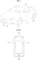
- FIG. 1 is a diagram showing the appearance of a vehicle including around view cameras according to one embodiment of the present invention.
- the communication unit 120 may exchange data with a mobile terminal 600 and/or a server 500 in a wireless manner.
- the communication unit 120 may exchange data with the mobile terminal of the driver in a wireless manner.
- the wireless communication method may include various data communication methods such as Bluetooth, Wi-Fi Direct, Wi-Fi or APiX.
- the communication unit 120 may receive weather information and road traffic state information, e.g., Transport Protocol Experts Group (TPEG) information, from the mobile terminal 600 and/or the server 500.
- TPEG Transport Protocol Experts Group
- real-time traffic information obtained based on the images may be transmitted to the mobile terminal 600 and/or the server 500.
- An audio output unit converts an electrical signal from the processor 170 into an audio signal and outputs the audio signal.
- the audio output unit may include a speaker.
- the audio output unit (not shown) may output sound corresponding to operation of the input unit 110, that is, a button.
- An audio input unit may receive user voice and may include a microphone.
- the received voice may be converted into an electrical signal and the electrical signal may be delivered to the processor 170.
- the processor 170 may calculate a distance from a detected peripheral vehicle or pedestrian.
- the display 180 may display the around view image generated by the processor 170. Upon displaying the around view image, various user interfaces may be provided and a touch sensor for enabling touch input through the provided user interface may be included.
- the display 180 may include a cluster or a head up display (HUD) located at the internal front side of the vehicle.
- HUD head up display
- a projection module for projecting an image on the windshield of the vehicle 200 may be included.
- the image projector 187 may include a laser diode (210 of FIG. 4A ) for outputting visible light corresponding to the projected image.
- a scanner for externally outputting visible light using a scanning method may be further included.
- the around view provision apparatus 100 of FIG. 3B is similar to the around view provision apparatus 100 of FIG. 3A but is different therefrom in that an input unit 110 and an ultrasonic sensor unit 198 are further included.
- an input unit 110 and an ultrasonic sensor unit 198 are further included.
- only the input unit 110 and the ultrasonic sensor units 198 will be described.
- the optical unit 205 may include a light source unit 210 including a plurality of light sources. That is, a red light source unit 210R, a green light source unit 210G and a blue light source unit 210B may be included. At this time, the red light source unit 210R, the green light source unit 210G and the blue light source unit 210B may include red, green and blue laser diodes, respectively.
- the light source units 210R, 210G and 210B may be driven by electrical signals from the drive unit 185 and the electrical signals of the drive unit 185 may be generated under control of the processor 170.
- a light output unit 60 may include a laser diode 62, a mirror 65 and a scanner 240.
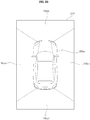
- the external area 40 may be divided into a first area 42 and a second area 44, as shown in FIG. 4B .
- the first area 42 may be an area including an external object 43, that is, an active area 42
- the second area 44 may be an area without an external object, that is, a blank area 44.
- an entire scanning area may be divided into a first scanning area corresponding to the active area 42 including the external object and a second scanning area corresponding to the blank area 44 without the external object.
- a region having disparity information of a predetermined value or more in the disparity map may be calculated as the foreground and be extracted. Therefore, the background may be segmented.
- the object detector 434 may detect an object based on image segmentation of the segmentation unit 432.
- the object detector 434 may detect the object from at least one of the images.
- the object may be detected from the foreground segmented by segmentation.
- the disparity map 520 has disparity levels respectively corresponding to first to fourth lanes 528a, 528b, 528c and 528d, for example, disparity levels respectively corresponding to a construction area 522, a first preceding vehicle 524 and a second preceding vehicle 526.
- the segmentation unit 432, the object detector 434 and the object verification unit 436 may perform segmentation, object detection and object verification with respect to at least one of the images FR1a and FR1b based on the disparity map 520.
- the object tracking unit 440 may track the verified objects by continuously acquiring the images.
- the communication unit 720 may exchange data with the mobile terminal 600 or the server 500 in a wireless manner.
- the communication unit 720 may exchange data with a mobile terminal of a vehicle driver in a wireless manner.
- a wireless data communication method includes various data communication methods such as Bluetooth, Wi-Fi Direct, Wi-Fi, APiX, etc.
- the communication unit 720 may receive weather information and road traffic state information, e.g., Transport Protocol Experts Group (TPEG) information, from the mobile terminal 600 or the server 500.
- TPEG Transport Protocol Experts Group
- the sensing unit 760 may acquire sensing signals with regard to, for example, vehicle traveling direction information, vehicle position information (GPS information), vehicle angle information, vehicle speed information, vehicle acceleration information, vehicle tilt information, vehicle forward/reverse information, battery information, fuel information, tire information, vehicle lamp information, vehicle interior temperature information, vehicle interior humidity information, etc.
- vehicle traveling direction information for example, vehicle traveling direction information, vehicle position information (GPS information), vehicle angle information, vehicle speed information, vehicle acceleration information, vehicle tilt information, vehicle forward/reverse information, battery information, fuel information, tire information, vehicle lamp information, vehicle interior temperature information, vehicle interior humidity information, etc.
- the ECU 770 may synthesize a plurality of images received from the plurality of cameras 795 to generate an around view image.
- the around view image may be generated.
- the display 780 may include a cluster or a head up display (HUD) located at the internal front side of the vehicle.
- HUD head up display
- a projection module for projecting an image onto the windshield of the vehicle 200 may be included.
- the display 780 may include a touchscreen capable of performing an input function.
- the location of at least one of the plurality of around view cameras 195a, 195b, 195c and 195d may be changed.
- edge increase or image breaking may be generated in a boundary area between the images.
- FIG. 8 is a flowchart illustrating a method of operating an around view provision apparatus according to an embodiment of the present invention.
- the processor 170 of the around view provision apparatus 100 receives a plurality of images 820a to 820d captured by the plurality of around view cameras 195a, 195b, 195c and 195d (S710).
- the plurality of around view cameras 195a, 195b, 195c and 195d may be disposed at the left, rear, right and front sides of the vehicle.
- the processor 170 of the around view provision apparatus 100 may extract first area patterns in the plurality of images 820a to 820d (S720), for image calibration, when the plurality of images 820a to 820d captured by the plurality of around view cameras 195a, 195b, 195c and 195d is received.
- the processor 170 of the around view provision apparatus 100 may calculate coordinates of a specific point based on the compensated parameter (S750).
- FIGS. 9A to 10 are views referenced to explain the operating method of FIG. 8 .
- the markers may be provided in a personal parking space.
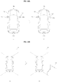
- FIG. 9B shows the marker 800 in greater detail.
- the marker 800 may include a checker board pattern. As shown in the figure, 20 rectangles may be provided and black rectangles and white rectangles are alternately provided.
- Each of the plurality of images 820a to 820d may include the first area pattern 810a and the second area pattern 810b.
- the processor 170 of the around view provision apparatus 100 may compensate the horizontal translation parameter.
- FIG. 11 is a flowchart illustrating a method of operating an around view provision apparatus according to an embodiment of the present invention
- FIGS. 12A to 13D are views referenced to explain the operating method of FIG. 11 .
- the plurality of images captured by the plurality of around view cameras 195a, 195b, 195c and 195d may be delivered to the processor 170 of the vehicle 200.
- Such image calibration may be performed upon startup of the vehicle, upon manipulating the side-view mirror or when impulse upon driving the vehicle is equal to or greater than a predetermined value.
- the processor 170 of the around view provision apparatus 100 calculates offset information based on a difference between the captured image and the reference image (S1730).
- the processor 170 may calculate the offset information based on a difference between an object in the reference image and an object in the captured image, if each of the reference image and the captured image includes the object located outside the vehicle.
- the object located outside the vehicle may include at least one of a parking curb of a parking lot, a pillar, or a traffic sign, a traffic light, a street lamp, etc.
- the processor 170 may perform control to display the calibrated around view image through the display 180.
- the processor 170 may perform control to change at least one of the calibrated area, the amount of calibration or the offset information in correspondence with user input. Therefore, it is possible to increase user convenience.
- FIG. 12A shows the case where the location of the right camera 195c of the plurality of cameras 195a, 195b, 195c and 195d is changed.
- the location of the camera 195c is changed from the right side Lo1 to the right rear side Lo2.
- the reference image and the captured image are compared or reference location information and current location information of the camera are compared using a gyroscope sensor.
- the processor 170 may calculate the offset information using such a difference.
- the processor 170 may perform control to apply calculated first offset information to the second and third cameras adjacent to the first camera.
- the processor 170 may perform control to perform calibration with respect to the rear camera 195b and the front camera 195d adjacent to the right camera 195c using the calculated offset information offset1.
- the processor 170 may partially apply the calculated offset information offset1 to the image captured by the front camera 195d or the rear camera 195b to acquire the calibrated image. Based on these images, the around view image may be generated.
- an around view provision apparatus and a vehicle including the same includes a plurality of cameras mounted on a vehicle, a display, and a processor configured to receive a plurality of images from the plurality of cameras, to check locations of the images using first area patterns in the plurality of images, to compensate a parameter in an image using second area patterns located in overlapping areas between the plurality of images, and to generate an around view image based on the compensated parameter. Accordingly, it is possible to provide an accurate around view image based on a calibrated image.
- the processor calculates the coordinates of a specific point in the overlapping areas between the plurality of images based on the compensated parameter and synthesizes the plurality of images to generate the around view image based on the calculated coordinates. Accordingly, it is possible to provide an accurate around view image based on a calibrated image.
- the processor calculates offset information of at least some of the plurality of cameras based on a difference between the reference image corresponding to each of the plurality of cameras from a memory and a captured image from each of the plurality of cameras and synthesizes the images from the plurality of cameras using the offset information to generate the around view image. Accordingly, it is possible to provide an accurate around view image based on a calibrated image.
Landscapes
- Engineering & Computer Science (AREA)
- Mechanical Engineering (AREA)
- Physics & Mathematics (AREA)
- Multimedia (AREA)
- General Physics & Mathematics (AREA)
- Theoretical Computer Science (AREA)
- Transportation (AREA)
- Combustion & Propulsion (AREA)
- Chemical & Material Sciences (AREA)
- Signal Processing (AREA)
- Automation & Control Theory (AREA)
- Computer Vision & Pattern Recognition (AREA)
- Mathematical Physics (AREA)
- Human Computer Interaction (AREA)
- Traffic Control Systems (AREA)
- Image Analysis (AREA)
- Closed-Circuit Television Systems (AREA)
- Image Processing (AREA)
Abstract
Description
- This application claims the benefit of Korean Patent Application No.
10-2016-0041033, filed on April 4, 2016 - The present invention relates to an around view provision apparatus and a vehicle including the same, and more particularly, to an around view provision apparatus capable of providing an accurate around view image based on a calibrated image, and a vehicle including the same. Furthermore, it relates to a method for operating an around view provision apparatus.
- A vehicle is an apparatus that allows a user who rides therein to drive the apparatus in a desired direction. A representative example of the vehicle may be an automobile.
- Meanwhile, for convenience of the user who uses the vehicle, the vehicle is provided with, for example, various sensors and electronic devices. In particular, for example, various devices for user driving convenience are being developed. Upon reversing or parking a vehicle, an image captured through a rear camera is being provided.
- An object of the present invention devised to solve the problem lies in an around view provision apparatus capable of providing an accurate around view image based on a calibrated image, and a vehicle including the same and a method for operating such around view provision apparatus.
- The object is solved by the features of the independent claims. Preferred embodimetns are given in the dependent claims.
- The object of the present invention can be achieved by providing an around view provision apparatus including a plurality of cameras mounted on a vehicle, a display, and a processor configured to receive a plurality of images from the plurality of cameras, to check locations of the images using first area patterns in the plurality of images, to compensate a parameter in an image using second area patterns located in overlapping areas between the plurality of images, and to generate an around view image based on the compensated parameter.
- Preferably, the processor may calculate coordinates of a specific point based on the compensated parameter and generates the around view image based on the calculated coordinates.
- Preferably, the processor may calculate the coordinates of the specific point in the overlapping areas between the plurality of images based on the compensated parameter and synthesizes the plurality of images to generate the around view image based on the calculated coordinates.
- Preferably, the first area patterns are located in front, rear, left and right areas of the vehicle, and the second area patterns are located in corner areas of the vehicle.
- Preferably, each of the first area patterns and/or the second area patterns (810b) includes a checker board pattern.
- Preferably, the apparatus may further include an image projector to output a projected image to an outside of the vehicle.
- Preferably, the processor may perform control to output the projected image including the first area patterns and/or the second area patterns to the outside of the vehicle, preferably when the vehicle is reversed or a speed of the vehicle is equal to or less than a predetermined speed.
- Preferably, the apparatus may further include a memory to store a reference image of each of the plurality of cameras.
- Preferably, the processor may calculate offset information of at least some of the plurality of cameras based on a difference between the reference image corresponding to each of the plurality of cameras from the memory and a captured image from each of the plurality of cameras and synthesizes the images from the plurality of cameras using the offset information to generate the around view image.
- Preferably, the processor may calculate first offset information based on a reference image of a first camera of the plurality of cameras and a captured image from the first camera and applies the calculated first offset information to the remaining cameras of the plurality of cameras.
- Preferably, each of the reference image and the captured image may include a character line of the vehicle.
- Preferably, the processor may calculate the offset information based on a difference between the character line in the reference image and the character line in the captured image.
- Preferably, the processor may output a notification message indicating that the around view image cannot be generated if the offset information is equal to or greater than a predetermined value.
- In another aspect of the present invention, provided herein is a vehicle including a steering drive unit to drive a steering apparatus, a brake drive unit to drive a brake apparatus, a power source drive unit to drive a power source, a plurality of cameras mounted on the vehicle, a display, and a processor configured to receive a plurality of images from the plurality of cameras, to check locations of the images using first area patterns in the plurality of images, to compensate a parameter in an image using second area patterns located in overlapping areas between the plurality of images, and to generate an around view image based on the compensated parameter.
- In a further aspect a method is provided for operating an around view provision apparatus, preferably the around view provision apparatus as mentioned above, the method comprising the steps of: receiving a plurality of images captured by a plurality of around view cameras, extracting first area patterns in the plurality of images for image calibration, checking locations of the cameras using the first area patterns in the plurality of images, extracting second area patterns in the plurality of images and compensate a parameter using the second area patterns; calculating coordinates of a specific point based on the compensated parameter; and generating an around view image based on the calculated specific point.
-
-
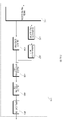
FIG. 1 is a diagram showing the appearance of a vehicle including around view cameras according to one embodiment of the present invention. -
FIG. 2A is a schematic diagram showing the positions of the around view cameras attached to the vehicle ofFIG. 1 . -
FIG. 2B is a diagram showing an around view image based on images captured by the around view cameras ofFIG. 2A . -
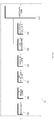
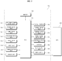
FIGS. 3A to 3B are block diagrams showing various examples of the internal configuration of an apparatus for providing an around view according to one embodiment of the present invention. -
FIG. 4A is a block diagram showing an example of the internal configuration of an image projector of the around view provision apparatus ofFIG. 3A or 3b . -
FIG. 4B is a diagram showing a scanning method upon image projection of the image projector ofFIG. 4A . -
FIGS. 5A to 5B are block diagrams the internal configuration of the processor ofFIG. 3 . -
FIG. 6 is a diagram showing object detection in the processor ofFIGS. 5A or5B . -
FIG. 7 is a block diagram showing the inside of a vehicle according to an embodiment of the present invention. -
FIG. 8 is a flowchart illustrating a method of operating an around view provision apparatus according to an embodiment of the present invention. -
FIGS. 9A to 10 are views referenced to explain the operating method ofFIG. 8 . -
FIG. 11 is a flowchart illustrating a method of operating an around view provision apparatus according to an embodiment of the present invention. -
FIGS. 12A to 13D are views referenced to explain the operating method ofFIG. 11 . - Hereinafter, the present invention will be described in detail with reference to the accompanying drawings.
- With respect to constituent elements used in the following description, suffixes "module" and "unit" are given or mingled with each other only in consideration of ease in preparation of the specification, and do not have or serve as different meanings. Accordingly, the terms "module" and "unit" may be used interchangeably.
- A vehicle as described in this specification may include an automobile and a motorcycle. Hereinafter, an automobile will be focused upon.
- A vehicle as described in this specification may include all of a vehicle including an engine, a hybrid vehicle including both an engine and an electric motor, and an electric vehicle including an electric motor.
- An around view provision apparatus as described in this specification includes may be an apparatus which includes a plurality of cameras and synthesizes a plurality of images captured by the plurality of cameras to provide an around view image. In particular, the apparatus may provide a top view or a bird eye view based on a vehicle. Hereinafter, an around view provision apparatus and a vehicle including the same according to various embodiments of the present invention will be described.
-
FIG. 1 is a diagram showing the appearance of a vehicle including around view cameras according to one embodiment of the present invention. - Referring to the figure, a
vehicle 200 may include wheels 103FR, 103FL, 103RL, ... rotated by a power source, asteering wheel 150 for controlling the direction of travel of thevehicle 200, and a plurality ofaround view cameras vehicle 200. In the figure, for convenience, only aleft camera 195a and afront camera 195d are shown. - The plurality of
around view cameras FIG. 3A or 3B ). -
FIG. 2 is a schematic diagram showing the positions of the around view cameras attached to the vehicle ofFIG. 1 , andFIG. 2B is a diagram showing an around view image based on images captured by the around view cameras ofFIG. 2A . - First, referring to
FIG. 2A , the plurality ofaround view cameras - In particular, the
left camera 195a and the right camera 915c may be disposed in a case surrounding a left side-view mirror and a case surrounding a right side-view mirror, respectively. - The
rear camera 195b and thefront camera 195d may be disposed near a trunk switch or on or near an emblem. - The plurality of images captured by the plurality of
around view cameras FIG. 3A or 3B ) of thevehicle 200 and the processor (170 ofFIG. 3A or 3B ) synthesizes the plurality of images to generate an around view image. -
FIG. 2B shows an example of thearound view image 210. Thearound view image 210 may include a first image area 195ai of theleft camera 195a, a second image area 195bi of therear camera 195b, a third image area 195ci of theright camera 195c and a fourth image area 195di of thefront camera 195d. -
FIGS. 3A to 3B are block diagrams showing various examples of the internal configuration of an around view provision apparatus according to one embodiment of the present invention. - The around
view provision apparatus 100 ofFIGS. 3A or 3B may synthesize the plurality of images received from the plurality ofaround view cameras - The around
view provision apparatus 100 may detect, verify and track an object located near the vehicle based on the plurality of images received from the plurality ofaround view cameras - First, referring to
FIG. 3A , the aroundview provision apparatus 100 ofFIG. 3A may include acommunication unit 120, aninterface 130, amemory 140, aprocessor 170, adisplay 180, apower supply 190 and a plurality ofcameras 195a, ..., 195e. In addition, an audio input unit (not shown) and animage projector 187 for projecting an image to the outside of the vehicle may be further included. - The
communication unit 120 may exchange data with amobile terminal 600 and/or aserver 500 in a wireless manner. In particular, thecommunication unit 120 may exchange data with the mobile terminal of the driver in a wireless manner. The wireless communication method may include various data communication methods such as Bluetooth, Wi-Fi Direct, Wi-Fi or APiX. - The
communication unit 120 may receive weather information and road traffic state information, e.g., Transport Protocol Experts Group (TPEG) information, from themobile terminal 600 and/or theserver 500. In the aroundview provision apparatus 100, real-time traffic information obtained based on the images may be transmitted to themobile terminal 600 and/or theserver 500. - When a user gets into the
vehicle 100, themobile terminal 600 of the user and the aroundview provision apparatus 100 may pair with each other automatically or as the user executes an application. - The
interface 130 may receive vehicle related data or transmit signals processed or generated in theprocessor 170 to an external device. Theinterface 130 may perform data communication with anECU 770, an audio video navigation (AVN)apparatus 400 and asensor unit 760 using a wired or wireless communication method. - The
interface 130 may receive map information related to vehicle traveling through data communication with theAVN apparatus 400. - The
interface 130 may receive sensor information from theECU 770 or thesensor unit 760. - The sensor information may include at least one of vehicle direction information, vehicle position information (GPS information), vehicle angle information, vehicle speed information, vehicle acceleration information, vehicle tilt information, vehicle forward/reverse information, battery information, fuel information, tier information, vehicle lamp information, vehicle interior temperature information, vehicle interior humidity information, etc.
- Information related to vehicle traveling, such as vehicle direction information, vehicle position information, vehicle angle information, vehicle speed information and vehicle tilt information, may be referred to as vehicle traveling information.
- The
memory 140 may store a variety of data for overall operation of the aroundview provision apparatus 100, such as a program for processing or control of theprocessor 170. - An audio output unit (not shown) converts an electrical signal from the
processor 170 into an audio signal and outputs the audio signal. The audio output unit may include a speaker. The audio output unit (not shown) may output sound corresponding to operation of theinput unit 110, that is, a button. - An audio input unit (not shown) may receive user voice and may include a microphone. The received voice may be converted into an electrical signal and the electrical signal may be delivered to the
processor 170. - The
processor 170 controls overall operation of the units of the aroundview provision apparatus 100. - In particular, the
processor 170 may acquire a plurality of images from the plurality ofcameras - The
processor 170 may perform signal processing based on computer vision. For example, the processor may perform disparity calculation of the periphery of the vehicle based on the plurality of images or the generated around view image, perform object detection within the image based on the calculated disparity information, and continuously track motion of an object after object detection. - In particular, the
processor 170 may perform lane detection, peripheral vehicle detection, pedestrian detection, traffic sign detection, road surface detection, etc. upon object detection. - The
processor 170 may calculate a distance from a detected peripheral vehicle or pedestrian. - The
processor 170 may receive sensor information from theECU 770 or thesensor unit 760 through theinterface 130. The sensor information may include at least one of vehicle direction information, vehicle position information (GPS information), vehicle angle information, vehicle speed information, vehicle acceleration information, vehicle tilt information, vehicle forward/reverse information, battery information, fuel information, tier information, vehicle lamp information, vehicle interior temperature information, vehicle interior humidity information, etc. - The
display 180 may display the around view image generated by theprocessor 170. Upon displaying the around view image, various user interfaces may be provided and a touch sensor for enabling touch input through the provided user interface may be included. - The
display 180 may include a cluster or a head up display (HUD) located at the internal front side of the vehicle. When thedisplay 180 is a HUD, a projection module for projecting an image on the windshield of thevehicle 200 may be included. - The
audio output unit 185 may output sound based on the audio signal processed by theprocessor 170. Theaudio output unit 185 may include at least one speaker. - The
image projector 187 may output a projected image to the outside of the vehicle. In particular, the projected image may be output up to about 50 meters ahead. As a light source, a laser diode having good linearity may be used. - Alternatively, the
image projector 187 may output a plurality of pattern images to the periphery of the vehicle, for calibration of the around view image upon parking the vehicle. - The
image projector 187 may include a laser diode (210 ofFIG. 4A ) for outputting visible light corresponding to the projected image. For control of the output direction, output angle, output distance, etc. of the projected image, a scanner (240 ofFIG. 4A ) for externally outputting visible light using a scanning method may be further included. - The
image projector 187 may output the projected image to the road surface located outside the vehicle or an object located near the vehicle, such as a wall, such that a driver views the projected image. - The
image projector 187 may output the projected image to a fixed object, instead of a moving object, in order to prevent the field of vision of a driver of an oncoming vehicle from being obstructed. - The output direction, output angle, output distance, etc. of the projected image may be controlled by the
processor 170 based on the sensed object. - The
power supply 190 may supply power required to operate the respective components under control of thecontroller 170. In particular, thepower supply 190 may receive power from, for example, a battery (not illustrated) inside the vehicle. - The plurality of
cameras - The
camera 195e is mounted inside the vehicle to capture a user, that is, a driver. Theprocessor 170 may check the location of the driver based on the image from theindoor camera 195e, set blind spots through side-view mirrors or a rearview mirror in the vehicle, tilt at least some of the cameras to capture the blind spots, and operate in a blind spot detection (BSD) mode as a first mode. - Next, referring to
FIG. 3B , the aroundview provision apparatus 100 ofFIG. 3B is similar to the aroundview provision apparatus 100 ofFIG. 3A but is different therefrom in that aninput unit 110 and anultrasonic sensor unit 198 are further included. Hereinafter, only theinput unit 110 and theultrasonic sensor units 198 will be described. - The
input unit 110 may include a plurality of buttons attached near thedisplay 180 or a touchscreen provided on thedisplay 180. Through the plurality of buttons or the touchscreen, the aroundview provision apparatus 100 may be powered on. In addition, a variety of input operations may be performed. - The
ultrasonic sensor unit 198 may include a plurality of ultrasonic sensors. If the plurality of ultrasonic sensors is mounted in the vehicle, an object located near the vehicle may be sensed based on a difference between a transmitted ultrasonic wave and a received ultrasonic wave. - Unlike
FIG. 3B , a Lidar (not shown) may be included instead of theultrasonic sensor unit 198 or theultrasonic sensor unit 198 and the Lidar may be included. -
FIG. 4A is a block diagram showing an example of the internal configuration of the image projector of the around view provision apparatus ofFIG. 3A or 3B . - Referring to the figure, the
image projector 187 ofFIG. 4A includes anoptical unit 205 and a drive unit 186. - The
optical unit 205 may include alight source unit 210 including a plurality of light sources. That is, a redlight source unit 210R, a greenlight source unit 210G and a bluelight source unit 210B may be included. At this time, the redlight source unit 210R, the greenlight source unit 210G and the bluelight source unit 210B may include red, green and blue laser diodes, respectively. - The
light source units drive unit 185 and the electrical signals of thedrive unit 185 may be generated under control of theprocessor 170. - The red, green and blue lights output from the
light source units - A
photosynthetic unit 220 synthesizes the lights output from thelight source units photosynthetic unit 220 includes three 2D MEMS mirrors 220a, 220b and 220c. - That is, the first
photosynthetic unit 220a, the secondphotosynthetic unit 220b and the thirdphotosynthetic unit 220c output red light output from the redlight source unit 210R, green light output from the greenlight source unit 210G and blue light output from the bluelight source 210B toward thescanner 240, respectively. - A
light reflection unit 256 reflects the red, green and blue lights passing through thephotosynthetic unit 220 toward thescanner 240. Thelight reflection unit 256 reflects lights having various wavelengths and thus may be implemented as a total mirror (TM). - The
scanner 240 may receive visible light (RGB) based on the red, green and blue lights from thelight source unit 210 and may sequentially and repeatedly perform first-direction scanning and second-direction scanning. Such scanning operations may be repeatedly performed with respect to an external scan area. Therefore, a projected image corresponding to visible light (RGB) may be externally displayed. -
FIG. 4B is a diagram showing a scanning method upon image projection of the image projector ofFIG. 4A . - Referring to the figure, a light output unit 60 may include a
laser diode 62, amirror 65 and ascanner 240. - The wavelength of light output from the light output unit 60 may correspond to the wavelength of visible light.
- Visible light output from the
laser diode 62 may be reflected and scattered by themirror 65 and input to thescanner 240. - The
scanner 240 may receive visible light from themirror 65 and sequentially and repeatedly perform first-direction scanning and second-direction scanning. - As shown in the figure, the
scanner 240 may perform left-to-right scanning or right-to-left scanning in a diagonal direction or a horizontal direction with respect to theexternal area 40 based on a scan-capable area. Such scanning operations may be repeatedly performed with respect to the whole of theexternal area 40. - By such scanning operations, the projected image may be externally output.
- The
external area 40 may be divided into afirst area 42 and asecond area 44, as shown inFIG. 4B . Thefirst area 42 may be an area including anexternal object 43, that is, anactive area 42, and thesecond area 44 may be an area without an external object, that is, ablank area 44. - Therefore, an entire scanning area may be divided into a first scanning area corresponding to the
active area 42 including the external object and a second scanning area corresponding to theblank area 44 without the external object. -
FIGS. 5A to 5B are block diagrams the internal configuration of the processor ofFIG. 3 , andFIG. 6 is a diagram showing object detection in the processor ofFIG. 5A or5B . - First, referring to
FIG. 5A, FIG. 5A is a block diagram showing an example of the internal configuration of theprocessor 170. Theprocessor 170 of the aroundview provision apparatus 100 may include animage pre-processor 410, adisparity calculator 420, anobject detector 434, anobject tracking unit 440 and anapplication 450. - The
image preprocessor 410 receives the plurality of images from the plurality ofcameras - More specifically, the
image preprocessor 410 may perform noise reduction, rectification, calibration, color enhancement, color space conversion (CSC), interpolation, camera gain control, etc. with respect to the plurality of images or the generated around view image. Therefore, it is possible to acquire images having higher definition than that of the images captured by the plurality ofcameras - The
disparity calculator 420 receives the plurality of images or the generated around view image processed by theimage preprocessor 410, performs stereo matching with respect to the plurality of images sequentially received during a predetermined time or the generated around view image, and acquires a disparity map according to stereo matching. That is, it is possible to acquire disparity information of the periphery of the vehicle. - At this time, stereo matching may be performed in pixel units of the stereo images or predetermined block units. The disparity map may mean a map numerically expressing the binocular parallax information of the images, that is, left and right images.
- A
segmentation unit 432 may perform segmentation and clustering with respect to the images based on the disparity information from thedisparity calculator 420. - More specifically, the
segmentation unit 432 may segment a background and a foreground with respect to at least one of the images based on the disparity information. - For example, a region having disparity information of a predetermined value or less in the disparity map may be calculated as the background and be excluded. Therefore, the foreground may be segmented.
- As another example, a region having disparity information of a predetermined value or more in the disparity map may be calculated as the foreground and be extracted. Therefore, the background may be segmented.
- The foreground and the background may be segmented based on the disparity information extracted based on the images, thereby reducing a signal processing speed, the amount of processed signals, etc. upon subsequent object detection.
- Next, the
object detector 434 may detect an object based on image segmentation of thesegmentation unit 432. - That is, the
object detector 434 may detect an object from at least one of the images based on the disparity information. - More specifically, the
object detector 434 may detect the object from at least one of the images. For example, the object may be detected from the foreground segmented by segmentation. - Next, an
object verification unit 436 classifies and verifies the segmented objects. - To this end, the
object verification unit 436 may use an identification method using a neural network, a support vector machine (SVM) method, an AdaBoost identification method using Haar-like features or a histograms-of-oriented-gradients (HOG) method, etc. - The
object verification unit 436 may compare the detected object with the objects stored in thememory 140 to verify the object. - For example, the
object verification unit 436 may verify a peripheral vehicle, a lane, a road surface, a traffic sign, a dangerous zone, a tunnel, etc. located in the vicinity of the vehicle. - The
object tracking unit 440 tracks the verified object. For example, objects in the sequentially acquired images may be verified, motion or motion vectors of the verified objects may be calculated and movement of the objects may be tracked based on the calculated motion or motion vectors. Therefore, it is possible to track the peripheral vehicle, the lane, the road surface, the traffic sign, the dangerous zone, the tunnel, etc. located in the vicinity of the vehicle. -
FIG. 5B is a block diagram showing another example of the internal configuration of the processor. - Referring to the figure, the
processor 170 ofFIG. 5B is equal to theprocessor 170 ofFIG. 5A except for a signal processing order. Hereinafter, only the difference will be described. - The
object detector 434 may receive the plurality of images or the generated around view image and detect the object from the plurality of images or the generated around view image. UnlikeFIG. 5A , the object may not be detected from the segmented image but may be directly detected from the plurality of images or the generated around view image based on the disparity information. - Next, the
object verification unit 436 classifies and verifies the segmented and detected object based on the image segment from thesegmentation unit 432 and the object detected by theobject detector 434. - To this end, the
object verification unit 436 may use an identification method using a neural network, a support vector machine (SVM) method, an AdaBoost identification method using Haar-like features or a histograms-of-oriented-gradients (HOG) method, etc. -
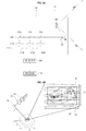
FIG. 6 is a diagram referenced to explain a method of operating theprocessor 170 ofFIG. 5 based on images respectively acquired in first and second frame periods. - Referring to
FIG. 6 , the plurality ofcameras 195a, ..., 195d sequentially acquires images FR1a and FR1b during the first and second frame periods. - The
disparity calculator 420 of theprocessor 170 receives the images FR1a and FR1b processed by theimage preprocessor 410, performs stereo matching with respect to the images FR1a and FR1b, and acquires adisparity map 520. - The
disparity map 520 expresses the binocular parallax level between the stereo images FR1a and FR1b. As a disparity level increases, a distance from a vehicle decreases and, as the disparity level decreases, the distance from the vehicle increases. - When such a disparity map is displayed, as the disparity level increases, luminance increases and, as the disparity level decreases, luminance decreases.
- In the figure, the
disparity map 520 has disparity levels respectively corresponding to first tofourth lanes construction area 522, a first precedingvehicle 524 and a secondpreceding vehicle 526. - The
segmentation unit 432, theobject detector 434 and theobject verification unit 436 may perform segmentation, object detection and object verification with respect to at least one of the images FR1a and FR1b based on thedisparity map 520. - In the figure, object detection and verification are performed with respect to the second image FR1b using the
disparity map 520. - That is, the first to
fourth lanes construction area 532, the first precedingvehicle 534 and the second precedingvehicle 536 are detected and verified from theimage 530 as objects. - The
object tracking unit 440 may track the verified objects by continuously acquiring the images. -
FIG. 7 is a block diagram showing the inside of a vehicle according to an embodiment of the present invention. - Referring to the figure, the
vehicle 200 may include anelectronic control apparatus 700 for vehicle control. Theelectronic control apparatus 700 may exchange data with theAVN apparatus 400. - The
electronic control apparatus 700 may include aninput unit 710, a communication unit 720, amemory 740, alamp drive unit 751, asteering drive unit 752, abrake drive unit 753, a powersource drive unit 754, a sunroof drive unit, asuspension drive unit 756, an airconditioner drive unit 757, awindow drive unit 758, anairbag drive unit 759, asensor unit 760, anECU 770, adisplay 780, anaudio output unit 785, apower supply 790 and a plurality ofcameras 795. - The
ECU 770 may include a processor. Alternatively, in addition to theECU 770, a processor for processing the images from the cameras may be further included. - The
input unit 710 may include a plurality of buttons or a touchscreen provided inside thevehicle 200. Through the plurality of buttons or the touchscreen, a variety of input operations may be performed. - The communication unit 720 may exchange data with the
mobile terminal 600 or theserver 500 in a wireless manner. In particular, the communication unit 720 may exchange data with a mobile terminal of a vehicle driver in a wireless manner. A wireless data communication method includes various data communication methods such as Bluetooth, Wi-Fi Direct, Wi-Fi, APiX, etc. - For example, the communication unit 720 may receive weather information and road traffic state information, e.g., Transport Protocol Experts Group (TPEG) information, from the
mobile terminal 600 or theserver 500. - When a user gets into the vehicle, the
mobile terminal 600 of the user and theelectronic control apparatus 700 may pair with each other automatically or as the user executes an application. - The
memory 740 may store a variety of data for overall operation of theelectronic control apparatus 700, such as a program for processing or control of theECU 770. - The
lamp drive unit 751 may turn lamps arranged inside and outside the vehicle on or off. In addition, the lamp drive unit may control, for example, the intensity and direction of light of each lamp. For example, the lamp drive unit may perform control of a turn signal lamp or a brake lamp. - The
steering drive unit 752 may perform electronic control of a steering apparatus inside thevehicle 200. The steering drive unit may change the direction of travel of the vehicle. - The
brake drive unit 753 may perform electronic control of a brake apparatus (not illustrated) inside thevehicle 200. For example, the brake drive unit may reduce the speed of thevehicle 200 by controlling the operation of brakes located at wheels. In another example, the brake drive unit may adjust the direction of travel of thevehicle 200 leftward or rightward by differentiating the operation of respective brakes located at left and right wheels. - The power
source drive unit 754 may perform electronic control of a power source inside thevehicle 200. - For example, in the case where a fossil fuel based engine (not illustrated) is a power source, the power
source drive unit 754 may perform electronic control of the engine. Therefore, it is possible to control output torque of the engine. - In another example, in the case where an electric motor (not illustrated) is a power source, the power
source drive unit 754 may perform control of the motor. As such, the power source drive unit may control, for example, the RPM and torque of the motor. - The
sunroof drive unit 755 may perform electronic control of a sunroof apparatus (not illustrated) inside thevehicle 200. For example, the sunroof drive unit may control opening or closing of a sunroof. - The
suspension drive unit 756 may perform electronic control of a suspension apparatus inside thevehicle 200. For example, when a road surface is uneven, the suspension drive unit may control the suspension apparatus to reduce vibration of thevehicle 200. - The air
conditioner drive unit 757 may perform electronic control of an air conditioner (not illustrated) inside thevehicle 200. For example, when the interior temperature of thevehicle 200 is high, the air conditioner drive unit may operate the air conditioner to supply cold air to the interior of thevehicle 200. - The
window drive unit 758 may perform electronic control of a window apparatus inside thevehicle 200. For example, the window drive unit may control opening or closing of left and right windows of thevehicle 200. - The
airbag drive unit 759 may perform the electronic control of an airbag apparatus inside thevehicle 200. For example, the airbag drive unit may control an airbag to be deployed in a dangerous situation. - The
sensing unit 760 is configured to sense signals associated with traveling of thevehicle 100. To this end, thesensing unit 760 may include a heading sensor, a yaw sensor, a gyro sensor, a position module, a vehicle forward/reverse sensor, a wheel sensor, a vehicle speed sensor, a vehicle tilt sensor, a battery sensor, a fuel sensor, a tire sensor, a steering sensor based on rotation of the steering wheel, a vehicle interior temperature sensor, a vehicle interior humidity sensor, etc. - As such, the
sensing unit 760 may acquire sensing signals with regard to, for example, vehicle traveling direction information, vehicle position information (GPS information), vehicle angle information, vehicle speed information, vehicle acceleration information, vehicle tilt information, vehicle forward/reverse information, battery information, fuel information, tire information, vehicle lamp information, vehicle interior temperature information, vehicle interior humidity information, etc. - Meanwhile, the
sensing unit 760 may further include, for example, an accelerator pedal sensor, a pressure sensor, an engine speed sensor, an Air Flow-rate Sensor (AFS), an Air Temperature Sensor (ATS), a Water Temperature Sensor (WTS), a Throttle Position Sensor (TPS), a Top Dead Center (TDC) sensor, and a Crank Angle Sensor (CAS). - The
ECU 770 may control overall operation of the units of theelectronic control apparatus 700. - The ECU may perform specific operation based on input received through the
input unit 710 or receive and transmit the signal sensed by thesensor unit 760 to the aroundview provision apparatus 100, receive map information from theAVN apparatus 400 and control operations of thedrive units - In addition, the
ECU 770 may receive weather information and road traffic state information, e.g., Transport Protocol Experts Group (TPEG) information, from the communication unit 720. - The
ECU 770 may synthesize a plurality of images received from the plurality ofcameras 795 to generate an around view image. In particular, when the speed of the vehicle is equal to or less than a predetermined speed or when the vehicle is reversed, the around view image may be generated. - The
display 780 may display the generated around view image. In particular, various user interface may be provided in addition to the around view image. - For display of the around view image, the
display 780 may include a cluster or a head up display (HUD) located at the internal front side of the vehicle. When thedisplay 780 is a HUD, a projection module for projecting an image onto the windshield of thevehicle 200 may be included. Thedisplay 780 may include a touchscreen capable of performing an input function. - The
audio output unit 785 converts an electrical signal from theECU 770 into an audio signal and outputs the audio signal. The audio output unit may include a speaker. Theaudio output unit 785 may output sound corresponding to operation of theinput unit 110, that is, a button. - The
power supply 790 may supply power required to operate the respective components under control of theECU 770. In particular, thepower supply 790 may receive power from, for example, a battery (not illustrated) inside the vehicle. - The plurality of
cameras 795 is used to provide the around view image and may include four cameras as shown inFIG. 2A . For example, the plurality ofaround view cameras cameras 795 may be delivered to theECU 770 or the processor (not shown). - Although not shown in the figure, the
electronic control apparatus 700 of thevehicle 200 may include theimage projector 187 ofFIG. 3A or 3B . - Upon driving or parking the vehicle, the location of at least one of the plurality of
around view cameras - For example, upon driving the vehicle, if impulse upon passing over a speed bump is equal to or greater than a predetermined value, the location of at least one of the plurality of
around view cameras - As another example, the location of at least one of the
left camera 195a and theright camera 195c disposed at the side-view mirrors may be changed by a pedestrian or another vehicle parked adjacent thereto in a state in which the vehicle is parked. - In a state in which the location of at least one of the plurality of
around view cameras processor 170 synthesizes the images captured by the cameras to generate the around view image, edge increase or image breaking may be generated in a boundary area between the images. - In the present invention, in order to prevent this phenomenon, auto-calibration is performed with respect to the plurality of
around view cameras - For example, calibration may be performed with respect to the images captured by the plurality of
around view cameras FIGS. 7 to 10 . - As another example, the reference images and the images captured by the plurality of
around view cameras FIGS. 11 to 14 . -
FIG. 8 is a flowchart illustrating a method of operating an around view provision apparatus according to an embodiment of the present invention. - Referring to
FIG. 8 , theprocessor 170 of the aroundview provision apparatus 100 receives a plurality ofimages 820a to 820d captured by the plurality ofaround view cameras - As shown in
FIG. 2 , the plurality ofaround view cameras - In particular, the
left camera 195a and the right camera 915c may be disposed in a case surrounding a left side-view mirror and a case surrounding a right side-view mirror, respectively. - The
rear camera 195b and thefront camera 195d may be disposed near a trunk switch or on or near an emblem. - The plurality of images captured by the plurality of
around view cameras processor 170 of the aroundview provision apparatus 100. - Next, the
processor 170 of the aroundview provision apparatus 100 may extract first area patterns in the plurality ofimages 820a to 820d (S720), for image calibration, when the plurality ofimages 820a to 820d captured by the plurality ofaround view cameras - Such image calibration may be performed upon startup of the vehicle, upon manipulating the side-view mirror or when impulse upon driving the vehicle is equal to or greater than a predetermined value.
- Such image calibration may be performed when the speed of the vehicle is equal to or less than a predetermined speed or when the vehicle is reversed.
- The first area patterns may be located in the front, rear, left and right areas of the
vehicle 200 and may include a checker board pattern. - Next, the
processor 170 of the aroundview provision apparatus 100 may check the locations of the cameras using the first area patterns in the plurality ofimages 820a to 820d (S730). - Next, the
processor 170 of the aroundview provision apparatus 100 may extract second area patterns in the plurality ofimages 820a to 820d and compensate a parameter using the second area patterns overlapped between adjacent cameras (S740). - The second area patterns may be located at corner areas of the
vehicle 200 and may include a checker board pattern. - The parameter may include at least one of a focal length parameter, a horizontal translation parameter, a vertical translation parameter, a longitudinal translation parameter, a pitch rotation parameter, a roll rotation parameter, a yaw rotation parameter and a camera intrinsic parameter.
- Next, the
processor 170 of the aroundview provision apparatus 100 may calculate coordinates of a specific point based on the compensated parameter (S750). - The specific point may correspond to the boundary of the checker board pattern in the second area pattern.
- Next, the
processor 170 of the aroundview provision apparatus 100 may generate an around view image based on the calculated specific point (S760). - That is, the
processor 170 of the aroundview provision apparatus 100 may receive the plurality ofimages 820a to 820d from the plurality ofcameras 195a to 195d, check the location of each image using thefirst area patterns 810a of the plurality ofimages 820a to 820d, compensate the parameter of each image using thesecond area patterns 810b located in overlapping areas between the plurality ofimages 820a to 820d, and generate the around view image based on the compensated parameter. Therefore, it is possible to provide an accurate around view image based on the calibrated image. - The
processor 170 may calculate the coordinates of the specific image based on the compensated parameter and generate the around view image based on the calculated coordinates. - In particular, the
processor 170 may calculate the coordinates of the specific point in the overlapping areas between the plurality ofimages 820a to 820d based on the compensated parameter, and synthesize the plurality ofimages 820a to 820d to generate the around view image based on the calculated coordinates, thereby providing an accurate around view image based on the calibrated image. -
FIGS. 9A to 10 are views referenced to explain the operating method ofFIG. 8 . - First,
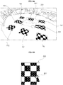
FIG. 9A shows a plurality of markers PA1 and PA2 provided in the periphery of a vehicle. - The plurality of markers PA1 and PA2 may be provided in a specific space, for calibration of the around
view provision apparatus 100. - For example, the markers may be provided in a personal parking space.
- The plurality of markers PA1 and PA2 may be projected images output from the
image projector 187, for calibration of the aroundview provision apparatus 100. - The plurality of markers PA1 and PA2 may include four first markers PA1 located in the front, rear, left and right areas of the
vehicle 200 and four second markers PA2 located at the corner areas of the vehicle. -
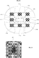
FIG. 9B shows themarker 800 in greater detail. - The
marker 800 may include a checker board pattern. As shown in the figure, 20 rectangles may be provided and black rectangles and white rectangles are alternately provided. - In the present invention, calibration is performed with respect to the image captured by the camera, using the boundary of the checker board pattern, that is, the
boundary 801 between the black rectangle and the white rectangle. -
FIG. 9C is a diagram showing the plurality ofimages 820a to 820d acquired by the plurality ofcameras 195a to 195d. - Referring to the figure, the plurality of
images 820a to 820d may be acquired from the plurality ofaround view cameras - Each of the plurality of
images 820a to 820d may include thefirst area pattern 810a and thesecond area pattern 810b. - The
processor 170 of the aroundview provision apparatus 100 may receive the plurality ofimages 820a to 820d from the plurality ofaround view cameras first area patterns 810a in the plurality ofimages 820a to 820d. - That is, the
processor 170 of the aroundview provision apparatus 100 may check the plurality ofimages 820a to 820d from theleft camera 195a, therear camera 195b, theright camera 195c and thefront camera 195d using thefirst area patterns 810a of the plurality ofimages 820a to 820d. - Next, the
processor 170 of the aroundview provision apparatus 100 compensates the parameter of each image using thesecond area patterns 810b located in the overlapping areas between the plurality ofimages 820a to 820d. - In particular, the
processor 170 of the aroundview provision apparatus 100 may compare a plurality of adjacent images in the boundary areas (the areas corresponding to 801 ofFIG. 9B ) between the checker board patterns of thesecond area patterns 810b, check a difference between the images, and compensate the parameter of the image in order to compensate the difference. - For example, if an error is generated in a horizontal component, the
processor 170 of the aroundview provision apparatus 100 may compensate the horizontal translation parameter. - For example, if an error is generated in a vertical component, the
processor 170 of the aroundview provision apparatus 100 may compensate the vertical translation parameter. - For example, if an error is generated in a longitudinal direction, the
processor 170 of the aroundview provision apparatus 100 may compensate the longitudinal translation parameter. - For example, if an error is generated in a pitch component, the
processor 170 of the aroundview provision apparatus 100 may compensate the pitch rotation parameter. - For example, if an error is generated in a roll component, the
processor 170 of the aroundview provision apparatus 100 may compensate the roll rotation parameter. - For example, if an error is generated in a yaw component, the
processor 170 of the aroundview provision apparatus 100 may compensate the yaw rotation parameter. - The
processor 170 of the aroundview provision apparatus 100 may calibrate the plurality of images based on the compensated parameters and synthesize the calibrated images to generate an around view image. -
FIG. 10 shows anaround view image 830 generated based on the calibrated images obtained by performing calibration with respect to the plurality of images. - Therefore, it is possible to provide an accurate around view image.
- The
processor 170 of the aroundview provision apparatus 100 may calculate the coordinates of a specific point based on the compensated parameter and generate the around view image based on the calculated coordinates. - The specific point may correspond to the boundary area (the area corresponding to 801 of
FIG. 9B ) of the checker board pattern of eachsecond area pattern 810b. - The
processor 170 of the aroundview provision apparatus 100 may calculate the coordinates of the specific point in the area overlapped between the plurality ofimages 820a to 820d based on the compensated parameter and synthesize the plurality ofimages 820a to 820d to generate the around view image based on the calculated coordinates. - The
processor 170 of the aroundview provision apparatus 100 may receive reverse movement information or speed information of the vehicle from the ECU of the vehicle and then output the projected image including thefirst area patterns 810a and thesecond area patterns 810b to the outside of thevehicle 200 if thevehicle 200 is reversed or if the speed of the vehicle is equal to or less than a predetermined speed. - The
processor 170 of the aroundview provision apparatus 100 may compensate the parameter of the image using thefirst area patterns 810a and thesecond area patterns 810b included in the projected image and generate the around view image based on the compensated parameter, as described with reference toFIGS. 9A to 9C . Therefore, it is possible to generate and provide an accurate around view image. -
FIG. 11 is a flowchart illustrating a method of operating an around view provision apparatus according to an embodiment of the present invention, andFIGS. 12A to 13D are views referenced to explain the operating method ofFIG. 11 . - First, referring to
FIG. 11 , theprocessor 170 of the aroundview provision apparatus 100 receives the images captured by the plurality ofaround view cameras - As shown in
FIG. 2 , the plurality ofaround view cameras - In particular, the
left camera 195a and the right camera 915c may be disposed in a case surrounding a left side-view mirror and a case surrounding a right side-view mirror, respectively. - The
rear camera 195b and thefront camera 195d may be disposed near a trunk switch or on or near an emblem. - The plurality of images captured by the plurality of
around view cameras processor 170 of thevehicle 200. - Next, the
processor 170 of the aroundview provision apparatus 100 receives the reference image of each of the plurality ofaround view cameras - The
processor 170 of the aroundview provision apparatus 100 may make a request to transmit the reference image of each of the plurality ofaround view cameras memory 140, for image calibration, when the plurality of images captured by the plurality ofaround view cameras - Such image calibration may be performed upon startup of the vehicle, upon manipulating the side-view mirror or when impulse upon driving the vehicle is equal to or greater than a predetermined value.
- The
memory 140 may transmit the reference image in response to the request to transmit the reference image. A reference image related to a parking lot may be transmitted upon startup of the vehicle, and a reference image including an area including a vehicle or an image including a lane may be transmitted upon manipulating the side-view mirror or when impulse upon driving the vehicle is equal to or greater than a predetermined value. - Next, the
processor 170 of the aroundview provision apparatus 100 calculates offset information based on a difference between the captured image and the reference image (S1730). - The
processor 170 may calculate the offset information based on the difference between a character line in the reference image and a character line in the captured image, if each of the reference image and the captured image includes the character line of the vehicle. - Here, the character line of the vehicle may include a hood emblem, a hood edge line, etc.
- The
processor 170 may calculate the offset information based on a difference between an object in the reference image and an object in the captured image, if each of the reference image and the captured image includes the object located outside the vehicle. - Here, the object located outside the vehicle may include at least one of a parking curb of a parking lot, a pillar, or a traffic sign, a traffic light, a street lamp, etc.
- The
processor 170 may perform control to output a notification message indicating that an around view image cannot be generated through the output unit (not shown) including theaudio output unit 185 or thedisplay 180, if the offset information is equal to or greater than a predetermined value. - The
processor 170 may calculate information if impulse upon startup of the vehicle, upon manipulating the side-view mirror or upon driving the vehicle is equal to or greater than a predetermined value. - The
processor 170 may calculate first offset information based on the reference image of the first camera of the first tofourth cameras 195a, ..., 195d and the captured image from thefirst camera 195a and apply the first offset information to at least some of the second to fourth cameras. Accordingly, it is possible to conveniently use common offset information even when the location of a camera is changed. - Next, the
processor 170 of the aroundview provision apparatus 100 synthesizes the images captured by the plurality ofaround view cameras - The
processor 170 may perform control to display the calibrated around view image through thedisplay 180. - At this time, the
processor 170 may perform control to display an area calibrated by the offset information on the around view image displayed on thedisplay 180 or to display an amount of calibration. Therefore, it is possible to increase user convenience. - The
processor 170 may perform control to display the around view image generated using the offset information and a second around view image generated without using the off-set information on thedisplay 180. - The
processor 170 may perform control to continuously generate the around view image using the offset information, if the around view image is selected from between the around view image and the second around view displayed on thedisplay 180. Therefore, it is possible to increase user convenience. - When user input is received in a state in which the around view image and the area calibrated by the offset information displayed on the around view image are displayed on the
display 180 or in a state of displaying the amount of calibration, theprocessor 170 may perform control to change at least one of the calibrated area, the amount of calibration or the offset information in correspondence with user input. Therefore, it is possible to increase user convenience. -
FIGS. 12A to 12B show the case where the location of theright camera 195c of the plurality ofcameras - First,
FIG. 12A shows the case where the location of theright camera 195c of the plurality ofcameras camera 195c is changed from the right side Lo1 to the right rear side Lo2. - If the location of the
right camera 195c is changed, an image breaking phenomenon is generated in the vicinity of the boundary area between images upon generating the around view image. - (a) of
FIG. 12B shows anaround view image 210 when the location of theright camera 195c is not changed and (b) ofFIG. 12B shows anaround view image 210 when the location of theright camera 195c is changed to the right rear side. - (b) of
FIG. 12B shows image breaking or edge increase in theboundary area 803 between the image of therear camera 195b and the image of theright camera 195c. When the driver views thearound view image 211, the driver finds that theboundary area 803 is unnatural. - In the present invention, in order to solve this problem, the reference image and the captured image are compared or reference location information and current location information of the camera are compared using a gyroscope sensor.
-
FIG. 13A shows an image captured when the location of theright camera 195c is not changed and an image captured when the location of theright camera 195c is changed to the right rear side. - (a) of
FIG. 13A shows capturedimages around view cameras - (b) of
FIG. 13A shows capturedimages around view cameras - In comparison between (a) and (b) of
FIG. 13A , it can be seen that, when the location of theright camera 195c is changed to the right rear side, the capturedimages - The
processor 170 may calculate the offset information using such a difference. - That is, as shown in
FIG. 13B , theprocessor 170 may receive the reference image of theright camera, for example, theimage 910c of (a) of , from thememory 140 and receive the capturedimage 911c from theright camera 195c. - The
processor 170 may calculate a difference between thereference image 910c and the capturedimage 911c and calculate offset information based on the difference. That is, when the location of theright camera 195c is changed to the right rear side, offset information for calibrating a portion of the captured image to the left front side may be calculated. -
FIG. 13C shows another example of a reference image and a captured image. -
FIG. 13C shows the case where apredetermined object 921 is included in areference image 920 and the case where anobject 926 in animage 925 captured by theright camera 195c is shifted to the right rear side. - The
processor 170 may calculate a difference between thereference image 920 and the capturedimage 925 and calculate offset information offset1 based on the difference. That is, based on the difference between the locations of theobjects image 925 to the left front side may be calculated. - The
processor 170 may calibrate the capturedimage 925 using the calculated offset information offset1 to be equal to thereference image 920. - (a) of
FIG. 13D shows image breaking or edge increase in aboundary area 803 between an image of therear camera 195b and an image of theright camera 195c in anaround view image 211. - (b) of
FIG. 13D shows anaround view image 930 calibrated by theprocessor 170 based on offset information. Therefore, a natural image is generated in theboundary area 803 without an image breaking phenomenon. Accordingly, the around view provision apparatus may provide an accurate around view image based on the calibrated image. - The
processor 170 may perform control to apply calculated first offset information to the second and third cameras adjacent to the first camera. - That is, the
processor 170 may perform control to perform calibration with respect to therear camera 195b and thefront camera 195d adjacent to theright camera 195c using the calculated offset information offset1. - For example, the
processor 170 may partially apply the calculated offset information offset1 to the image captured by thefront camera 195d or therear camera 195b to acquire the calibrated image. Based on these images, the around view image may be generated. - As apparent from the above description, an around view provision apparatus and a vehicle including the same according to the embodiments of the present invention includes a plurality of cameras mounted on a vehicle, a display, and a processor configured to receive a plurality of images from the plurality of cameras, to check locations of the images using first area patterns in the plurality of images, to compensate a parameter in an image using second area patterns located in overlapping areas between the plurality of images, and to generate an around view image based on the compensated parameter. Accordingly, it is possible to provide an accurate around view image based on a calibrated image.
- In particular, the processor calculates the coordinates of a specific point in the overlapping areas between the plurality of images based on the compensated parameter and synthesizes the plurality of images to generate the around view image based on the calculated coordinates. Accordingly, it is possible to provide an accurate around view image based on a calibrated image.
- The processor calculates offset information of at least some of the plurality of cameras based on a difference between the reference image corresponding to each of the plurality of cameras from a memory and a captured image from each of the plurality of cameras and synthesizes the images from the plurality of cameras using the offset information to generate the around view image. Accordingly, it is possible to provide an accurate around view image based on a calibrated image.
- The around view provision apparatus or the method of operating the same according to the present invention may be implemented as code that can be written to a processor-readable recording medium provided in the vehicle driving assistance device or the vehicle and can thus be read by a processor. The processor-readable recording medium may be any type of recording device in which data can be stored in a computer-readable manner. Examples of the processor-readable recording medium include a ROM, a RAM, a CD-ROM, a magnetic tape, a floppy disk, optical data storage, and a carrier wave (e.g., data transmission over the Internet). The processor-readable recording medium may be distributed to a plurality of computer systems connected to a network so that processor-readable code is written thereto and executed therefrom in a decentralized manner.
- Although the preferred embodiments of the present invention have been disclosed for illustrative purposes, those skilled in the art will appreciate that various modifications, additions and substitutions are possible, without departing from the scope of the invention as disclosed in the accompanying claims. Such modifications should not be individually understood from the technical idea or prospect of the present invention.
Claims (15)
- An around view provision apparatus (100) comprising:a plurality of cameras (195a,195b,195c,195d) mounted on a vehicle (200);a display (180); anda processor (170) configured to receive a plurality of images (820a~820d) from the plurality of cameras (195a,195b,195c,195d), to check locations of the images using first area patterns (810a) in the plurality of images, to compensate a parameter in an image using second area patterns (810b) located in overlapping areas between the plurality of images, and to generate an around view image based on the compensated parameter.
- The around view provision apparatus according to claim 1, wherein the processor (170) calculates coordinates of a specific point based on the compensated parameter and generates the around view image based on the calculated coordinates.
- The around view provision apparatus according to claim 2, wherein the processor (170) calculates the coordinates of the specific point in the overlapping areas between the plurality of images based on the compensated parameter and synthesizes the plurality of images to generate the around view image based on the calculated coordinates.
- The around view provision apparatus according to any one of the preceding claims, wherein the first area patterns (810a) are located in front, rear, left and right areas of the vehicle, and the second area patterns (810b) are located in corner areas of the vehicle.
- The around view provision apparatus according to any one of the preceding claims, wherein the first area patterns (810a) and/or the second area patterns (810b) includes a checker board pattern.
- The around view provision apparatus according to any one of the preceding claims, further comprising an image projector (187) to output a projected image to an outside of the vehicle.
- The around view provision apparatus according to any one of the preceding claims,wherein the processor (170) is configured to perform control to output the projected image including the first area patterns and the second area patterns to the outside of the vehicle, when the vehicle is reversed or a speed of the vehicle is equal to or less than a predetermined speed.
- The around view provision apparatus according to any one of the preceding claims, further comprising a memory (140) to store a reference image of each of the plurality of cameras (195a,195b,195c,195d).
- The around view provision apparatus according to claim 8, wherein the processor (170) is configured to calculate offset information of at least some of the plurality of cameras based on a difference between the reference image corresponding to each of the plurality of cameras from the memory and a captured image from each of the plurality of cameras and synthesizes the images from the plurality of cameras using the offset information to generate the around view image.
- The around view provision apparatus according to any one of the preceding claims, wherein the processor (170) is configured to calculate first offset information based on a reference image of a first camera of the plurality of cameras and a captured image from the first camera and applies the calculated first offset information to the remaining cameras of the plurality of cameras.
- The around view provision apparatus according to any one of claims 7-10, wherein each of the reference image and the captured image includes a character line of the vehicle.
- The around view provision apparatus according to claim 11, wherein the processor (170) is configured to calculate the offset information based on a difference between the character line in the reference image and the character line in the captured image.
- The around view provision apparatus according to any one of claims 9-12, wherein the processor (170) is configured to to output a notification message indicating that the around view image cannot be generated if the offset information is equal to or greater than a predetermined value.
- A vehicle (200) comprising:a steering drive unit (752) to drive a steering apparatus;a brake drive unit (753) to drive a brake apparatus;a power source drive unit (754) to drive a power source; andan around view provision apparatus of any one of the claims 1 to 13.
- Method for operating an around view provision apparatus (100), comprising the steps of:receiving (S710) a plurality of images (820a to 820d) captured by a plurality of around view cameras (195a, 195b, 195c, 195d),extracting (S720) first area patterns (810a) in the plurality of images (820a to 820d) for image calibration,checking (S730) locations of the cameras (195a, 195b, 195c, 195d) using the first area patterns (810a) in the plurality of images (820a, 820d),extracting (S740) second area patterns (810b) in the plurality of images (820a, 820d) and compensate a parameter using the second area patterns (810b);calculating (S750) coordinates of a specific point based on the compensated parameter; andgenerating (S760) an around view image based on the calculated specific point.
Applications Claiming Priority (1)
| Application Number | Priority Date | Filing Date | Title |
|---|---|---|---|
| KR1020160041033A KR101949358B1 (en) | 2016-04-04 | 2016-04-04 | Apparatus for providing around view and Vehicle including the same |
Publications (2)
| Publication Number | Publication Date |
|---|---|
| EP3229204A1 true EP3229204A1 (en) | 2017-10-11 |
| EP3229204B1 EP3229204B1 (en) | 2019-06-05 |
Family
ID=58489550
Family Applications (1)
| Application Number | Title | Priority Date | Filing Date |
|---|---|---|---|
| EP17164753.0A Active EP3229204B1 (en) | 2016-04-04 | 2017-04-04 | Around view provision apparatus and vehicle including the same |
Country Status (4)
| Country | Link |
|---|---|
| US (1) | US10366512B2 (en) |
| EP (1) | EP3229204B1 (en) |
| KR (1) | KR101949358B1 (en) |
| CN (1) | CN107264402B (en) |
Families Citing this family (24)
| Publication number | Priority date | Publication date | Assignee | Title |
|---|---|---|---|---|
| KR101844885B1 (en) * | 2016-07-11 | 2018-05-18 | 엘지전자 주식회사 | Driver Assistance Apparatus and Vehicle Having The Same |
| JP6794879B2 (en) * | 2017-03-10 | 2020-12-02 | 株式会社タダノ | Person detection system for work vehicles and work vehicles equipped with this |
| JP6499226B2 (en) * | 2017-06-02 | 2019-04-10 | 株式会社Subaru | Car camera calibration device and car camera calibration method |
| US10579067B2 (en) * | 2017-07-20 | 2020-03-03 | Huawei Technologies Co., Ltd. | Method and system for vehicle localization |
| US9934440B1 (en) * | 2017-10-04 | 2018-04-03 | StradVision, Inc. | Method for monitoring blind spot of monitoring vehicle and blind spot monitor using the same |
| KR20190061536A (en) | 2017-11-28 | 2019-06-05 | 주식회사 로비텍 | Information providing system for vehicles |
| KR102470298B1 (en) * | 2017-12-01 | 2022-11-25 | 엘지이노텍 주식회사 | A method of correcting cameras and device thereof |
| JP6939580B2 (en) * | 2018-01-10 | 2021-09-22 | 株式会社デンソー | Image synthesizer for vehicles |
| CN108382306A (en) * | 2018-02-26 | 2018-08-10 | 江苏裕兰信息科技有限公司 | One kind 360 looks around lateral parking auxiliary system and its householder method |
| KR102030631B1 (en) * | 2018-02-27 | 2019-10-10 | (주)넥셀 | Method and apparatus for providing around view |
| US20210323469A1 (en) * | 2018-07-10 | 2021-10-21 | Lg Electronics Inc. | Vehicular around view image providing apparatus and vehicle |
| CN108995592B (en) * | 2018-08-02 | 2021-06-15 | 张士文 | car imaging system |
| KR102625960B1 (en) * | 2019-02-28 | 2024-01-18 | 삼성디스플레이 주식회사 | Vehicle display device and driving method of the same |
| KR102177878B1 (en) * | 2019-03-11 | 2020-11-12 | 현대모비스 주식회사 | Apparatus and method for processing image |
| KR102140526B1 (en) * | 2019-04-26 | 2020-08-04 | 주식회사 켐트로닉스 | Device for around view |
| KR102295809B1 (en) | 2019-10-25 | 2021-09-01 | 주식회사 멀티플아이 | Apparatus for acquisition distance for all directions of vehicle |
| KR102477510B1 (en) * | 2020-12-24 | 2022-12-14 | 주식회사 와이즈오토모티브 | Device and method for calibrating images captured by camera of vehicle |
| CN115416681A (en) * | 2021-11-17 | 2022-12-02 | 北京罗克维尔斯科技有限公司 | Vehicle operation process display method and device, vehicle and storage medium |
| CN115134537B (en) * | 2022-01-18 | 2024-08-06 | 长城汽车股份有限公司 | Image processing method and device and vehicle |
| KR20240066751A (en) | 2022-11-08 | 2024-05-16 | 현대자동차주식회사 | Vehicle, and method for calculating position of the same |
| KR20240094105A (en) * | 2022-11-28 | 2024-06-25 | 주식회사 티엔디 | System for correcting image used in around view monitoring |
| WO2025079979A1 (en) * | 2023-10-10 | 2025-04-17 | 주식회사 카데아 | Method and apparatus for matching camera image data for generating surround view, and method for analyzing video information generated by using same |
| CN120833380A (en) * | 2024-04-24 | 2025-10-24 | 光宝科技股份有限公司 | Kit device and calibration system |
| DE102024125878A1 (en) * | 2024-09-10 | 2026-03-12 | Dr. Ing. H.C. F. Porsche Aktiengesellschaft | Method for improving rear visibility from a motor vehicle and corresponding motor vehicle |
Citations (5)
| Publication number | Priority date | Publication date | Assignee | Title |
|---|---|---|---|---|
| US20070268118A1 (en) * | 2006-05-17 | 2007-11-22 | Hisayuki Watanabe | Surrounding image generating apparatus and method of adjusting metering for image pickup device |
| US20140036063A1 (en) * | 2012-08-06 | 2014-02-06 | Hyundai Mobis Co., Ltd. | Around view monitor system and monitoring method |
| US20140098229A1 (en) * | 2012-10-05 | 2014-04-10 | Magna Electronics Inc. | Multi-camera image stitching calibration system |
| US20150329048A1 (en) * | 2014-05-16 | 2015-11-19 | GM Global Technology Operations LLC | Surround-view camera system (vpm) online calibration |
| EP2955915A1 (en) * | 2014-06-10 | 2015-12-16 | LG Electronics Inc. | Around view provision apparatus and vehicle including the same |
Family Cites Families (12)
| Publication number | Priority date | Publication date | Assignee | Title |
|---|---|---|---|---|
| JP2006311222A (en) | 2005-04-28 | 2006-11-09 | Auto Network Gijutsu Kenkyusho:Kk | Vehicle periphery visual recognition device |
| WO2007144979A1 (en) * | 2006-06-12 | 2007-12-21 | Vexon, Inc. | Peptide derivative |
| US7450813B2 (en) * | 2006-09-20 | 2008-11-11 | Imra America, Inc. | Rare earth doped and large effective area optical fibers for fiber lasers and amplifiers |
| US7839431B2 (en) * | 2006-10-19 | 2010-11-23 | Robert Bosch Gmbh | Image processing system and method for improving repeatability |
| JP5299231B2 (en) * | 2009-11-17 | 2013-09-25 | 富士通株式会社 | Calibration device |
| KR20130056605A (en) * | 2011-11-22 | 2013-05-30 | 한양대학교 에리카산학협력단 | Apparatus and method for generating panorama image |
| US9030440B2 (en) * | 2012-05-18 | 2015-05-12 | Apple Inc. | Capacitive sensor packaging |
| CN103581013B (en) * | 2012-07-25 | 2017-02-15 | 杭州华三通信技术有限公司 | Method and device for achieving non-stop routing of routing protocol |
| JP6163453B2 (en) | 2014-05-19 | 2017-07-12 | 本田技研工業株式会社 | Object detection device, driving support device, object detection method, and object detection program |
| KR20150144090A (en) * | 2014-06-16 | 2015-12-24 | 현대모비스 주식회사 | Operating method of around view monitoring system |
| US20160048966A1 (en) * | 2014-08-13 | 2016-02-18 | Bendix Commercial Vehicle Systems Llc | Learning the distance between cameras for articulated vehicles |
| KR102227371B1 (en) * | 2014-09-19 | 2021-03-11 | 엘지전자 주식회사 | Image projection apparatus of vehicle and vehicle including the same |
-
2016
- 2016-04-04 KR KR1020160041033A patent/KR101949358B1/en active Active
-
2017
- 2017-04-04 US US15/479,212 patent/US10366512B2/en active Active
- 2017-04-04 EP EP17164753.0A patent/EP3229204B1/en active Active
- 2017-04-05 CN CN201710218269.0A patent/CN107264402B/en active Active
Patent Citations (5)
| Publication number | Priority date | Publication date | Assignee | Title |
|---|---|---|---|---|
| US20070268118A1 (en) * | 2006-05-17 | 2007-11-22 | Hisayuki Watanabe | Surrounding image generating apparatus and method of adjusting metering for image pickup device |
| US20140036063A1 (en) * | 2012-08-06 | 2014-02-06 | Hyundai Mobis Co., Ltd. | Around view monitor system and monitoring method |
| US20140098229A1 (en) * | 2012-10-05 | 2014-04-10 | Magna Electronics Inc. | Multi-camera image stitching calibration system |
| US20150329048A1 (en) * | 2014-05-16 | 2015-11-19 | GM Global Technology Operations LLC | Surround-view camera system (vpm) online calibration |
| EP2955915A1 (en) * | 2014-06-10 | 2015-12-16 | LG Electronics Inc. | Around view provision apparatus and vehicle including the same |
Also Published As
| Publication number | Publication date |
|---|---|
| CN107264402A (en) | 2017-10-20 |
| CN107264402B (en) | 2019-11-26 |
| US20170287168A1 (en) | 2017-10-05 |
| US10366512B2 (en) | 2019-07-30 |
| EP3229204B1 (en) | 2019-06-05 |
| KR101949358B1 (en) | 2019-02-18 |
| KR20170114105A (en) | 2017-10-13 |
Similar Documents
| Publication | Publication Date | Title |
|---|---|---|
| EP3229204B1 (en) | Around view provision apparatus and vehicle including the same | |
| EP2955915B1 (en) | Around view provision apparatus and vehicle including the same | |
| US9712791B2 (en) | Around view provision apparatus and vehicle including the same | |
| EP2955690B1 (en) | Around view provision apparatus and vehicle including the same | |
| KR102344171B1 (en) | Image generating apparatus, image generating method, and program | |
| EP3569447B1 (en) | Driver assistance apparatus | |
| EP3088268B1 (en) | Vehicle driving aid device and vehicle having same | |
| US10029607B2 (en) | Vehicle head lamp driving apparatus and vehicle provided with same | |
| US10782405B2 (en) | Radar for vehicle and vehicle provided therewith | |
| US9919611B2 (en) | Vehicle charge assistance device and vehicle including the same | |
| US20090086019A1 (en) | Driving support device, driving support method and computer program | |
| US11390297B2 (en) | Recognition device, recognition method, and storage medium | |
| KR101632179B1 (en) | Driver assistance apparatus and Vehicle including the same | |
| KR102227371B1 (en) | Image projection apparatus of vehicle and vehicle including the same | |
| KR101567405B1 (en) | apparatus for providing around view and Vehicle including the same |
Legal Events
| Date | Code | Title | Description |
|---|---|---|---|
| PUAI | Public reference made under article 153(3) epc to a published international application that has entered the european phase |
Free format text: ORIGINAL CODE: 0009012 |
|
| STAA | Information on the status of an ep patent application or granted ep patent |
Free format text: STATUS: REQUEST FOR EXAMINATION WAS MADE |
|
| 17P | Request for examination filed |
Effective date: 20170404 |
|
| AK | Designated contracting states |
Kind code of ref document: A1 Designated state(s): AL AT BE BG CH CY CZ DE DK EE ES FI FR GB GR HR HU IE IS IT LI LT LU LV MC MK MT NL NO PL PT RO RS SE SI SK SM TR |
|
| AX | Request for extension of the european patent |
Extension state: BA ME |
|
| RBV | Designated contracting states (corrected) |
Designated state(s): AL AT BE BG CH CY CZ DE DK EE ES FI FR GB GR HR HU IE IS IT LI LT LU LV MC MK MT NL NO PL PT RO RS SE SI SK SM TR |
|
| REG | Reference to a national code |
Ref country code: DE Ref legal event code: R079 Ref document number: 602017004254 Country of ref document: DE Free format text: PREVIOUS MAIN CLASS: G06T0003400000 Ipc: G06T0011600000 |
|
| GRAP | Despatch of communication of intention to grant a patent |
Free format text: ORIGINAL CODE: EPIDOSNIGR1 |
|
| STAA | Information on the status of an ep patent application or granted ep patent |
Free format text: STATUS: GRANT OF PATENT IS INTENDED |
|
| RIC1 | Information provided on ipc code assigned before grant |
Ipc: B60R 1/00 20060101ALI20181018BHEP Ipc: H04N 9/31 20060101ALI20181018BHEP Ipc: B60K 35/00 20060101ALI20181018BHEP Ipc: H04N 7/18 20060101ALI20181018BHEP Ipc: G06T 7/80 20170101ALI20181018BHEP Ipc: G06T 11/60 20060101AFI20181018BHEP Ipc: G06T 7/73 20170101ALI20181018BHEP Ipc: G06T 3/40 20060101ALI20181018BHEP |
|
| INTG | Intention to grant announced |
Effective date: 20181121 |
|
| GRAS | Grant fee paid |
Free format text: ORIGINAL CODE: EPIDOSNIGR3 |
|
| GRAA | (expected) grant |
Free format text: ORIGINAL CODE: 0009210 |
|
| STAA | Information on the status of an ep patent application or granted ep patent |
Free format text: STATUS: THE PATENT HAS BEEN GRANTED |
|
| AK | Designated contracting states |
Kind code of ref document: B1 Designated state(s): AL AT BE BG CH CY CZ DE DK EE ES FI FR GB GR HR HU IE IS IT LI LT LU LV MC MK MT NL NO PL PT RO RS SE SI SK SM TR |
|
| REG | Reference to a national code |
Ref country code: GB Ref legal event code: FG4D |
|
| REG | Reference to a national code |
Ref country code: CH Ref legal event code: EP |
|
| REG | Reference to a national code |
Ref country code: AT Ref legal event code: REF Ref document number: 1140770 Country of ref document: AT Kind code of ref document: T Effective date: 20190615 |
|
| REG | Reference to a national code |
Ref country code: IE Ref legal event code: FG4D |
|
| REG | Reference to a national code |
Ref country code: DE Ref legal event code: R096 Ref document number: 602017004254 Country of ref document: DE |
|
| REG | Reference to a national code |
Ref country code: NL Ref legal event code: MP Effective date: 20190605 |
|
| REG | Reference to a national code |
Ref country code: LT Ref legal event code: MG4D |
|
| PG25 | Lapsed in a contracting state [announced via postgrant information from national office to epo] |
Ref country code: AL Free format text: LAPSE BECAUSE OF FAILURE TO SUBMIT A TRANSLATION OF THE DESCRIPTION OR TO PAY THE FEE WITHIN THE PRESCRIBED TIME-LIMIT Effective date: 20190605 Ref country code: FI Free format text: LAPSE BECAUSE OF FAILURE TO SUBMIT A TRANSLATION OF THE DESCRIPTION OR TO PAY THE FEE WITHIN THE PRESCRIBED TIME-LIMIT Effective date: 20190605 Ref country code: LT Free format text: LAPSE BECAUSE OF FAILURE TO SUBMIT A TRANSLATION OF THE DESCRIPTION OR TO PAY THE FEE WITHIN THE PRESCRIBED TIME-LIMIT Effective date: 20190605 Ref country code: HR Free format text: LAPSE BECAUSE OF FAILURE TO SUBMIT A TRANSLATION OF THE DESCRIPTION OR TO PAY THE FEE WITHIN THE PRESCRIBED TIME-LIMIT Effective date: 20190605 Ref country code: SE Free format text: LAPSE BECAUSE OF FAILURE TO SUBMIT A TRANSLATION OF THE DESCRIPTION OR TO PAY THE FEE WITHIN THE PRESCRIBED TIME-LIMIT Effective date: 20190605 Ref country code: NO Free format text: LAPSE BECAUSE OF FAILURE TO SUBMIT A TRANSLATION OF THE DESCRIPTION OR TO PAY THE FEE WITHIN THE PRESCRIBED TIME-LIMIT Effective date: 20190905 |
|
| PG25 | Lapsed in a contracting state [announced via postgrant information from national office to epo] |
Ref country code: RS Free format text: LAPSE BECAUSE OF FAILURE TO SUBMIT A TRANSLATION OF THE DESCRIPTION OR TO PAY THE FEE WITHIN THE PRESCRIBED TIME-LIMIT Effective date: 20190605 Ref country code: LV Free format text: LAPSE BECAUSE OF FAILURE TO SUBMIT A TRANSLATION OF THE DESCRIPTION OR TO PAY THE FEE WITHIN THE PRESCRIBED TIME-LIMIT Effective date: 20190605 Ref country code: GR Free format text: LAPSE BECAUSE OF FAILURE TO SUBMIT A TRANSLATION OF THE DESCRIPTION OR TO PAY THE FEE WITHIN THE PRESCRIBED TIME-LIMIT Effective date: 20190906 Ref country code: BG Free format text: LAPSE BECAUSE OF FAILURE TO SUBMIT A TRANSLATION OF THE DESCRIPTION OR TO PAY THE FEE WITHIN THE PRESCRIBED TIME-LIMIT Effective date: 20190905 |
|
| REG | Reference to a national code |
Ref country code: AT Ref legal event code: MK05 Ref document number: 1140770 Country of ref document: AT Kind code of ref document: T Effective date: 20190605 |
|
| PG25 | Lapsed in a contracting state [announced via postgrant information from national office to epo] |
Ref country code: PT Free format text: LAPSE BECAUSE OF FAILURE TO SUBMIT A TRANSLATION OF THE DESCRIPTION OR TO PAY THE FEE WITHIN THE PRESCRIBED TIME-LIMIT Effective date: 20191007 Ref country code: AT Free format text: LAPSE BECAUSE OF FAILURE TO SUBMIT A TRANSLATION OF THE DESCRIPTION OR TO PAY THE FEE WITHIN THE PRESCRIBED TIME-LIMIT Effective date: 20190605 Ref country code: CZ Free format text: LAPSE BECAUSE OF FAILURE TO SUBMIT A TRANSLATION OF THE DESCRIPTION OR TO PAY THE FEE WITHIN THE PRESCRIBED TIME-LIMIT Effective date: 20190605 Ref country code: NL Free format text: LAPSE BECAUSE OF FAILURE TO SUBMIT A TRANSLATION OF THE DESCRIPTION OR TO PAY THE FEE WITHIN THE PRESCRIBED TIME-LIMIT Effective date: 20190605 Ref country code: SK Free format text: LAPSE BECAUSE OF FAILURE TO SUBMIT A TRANSLATION OF THE DESCRIPTION OR TO PAY THE FEE WITHIN THE PRESCRIBED TIME-LIMIT Effective date: 20190605 Ref country code: RO Free format text: LAPSE BECAUSE OF FAILURE TO SUBMIT A TRANSLATION OF THE DESCRIPTION OR TO PAY THE FEE WITHIN THE PRESCRIBED TIME-LIMIT Effective date: 20190605 Ref country code: EE Free format text: LAPSE BECAUSE OF FAILURE TO SUBMIT A TRANSLATION OF THE DESCRIPTION OR TO PAY THE FEE WITHIN THE PRESCRIBED TIME-LIMIT Effective date: 20190605 |
|
| PG25 | Lapsed in a contracting state [announced via postgrant information from national office to epo] |
Ref country code: IS Free format text: LAPSE BECAUSE OF FAILURE TO SUBMIT A TRANSLATION OF THE DESCRIPTION OR TO PAY THE FEE WITHIN THE PRESCRIBED TIME-LIMIT Effective date: 20191005 Ref country code: SM Free format text: LAPSE BECAUSE OF FAILURE TO SUBMIT A TRANSLATION OF THE DESCRIPTION OR TO PAY THE FEE WITHIN THE PRESCRIBED TIME-LIMIT Effective date: 20190605 Ref country code: IT Free format text: LAPSE BECAUSE OF FAILURE TO SUBMIT A TRANSLATION OF THE DESCRIPTION OR TO PAY THE FEE WITHIN THE PRESCRIBED TIME-LIMIT Effective date: 20190605 |
|
| REG | Reference to a national code |
Ref country code: DE Ref legal event code: R097 Ref document number: 602017004254 Country of ref document: DE |
|
| PG25 | Lapsed in a contracting state [announced via postgrant information from national office to epo] |
Ref country code: TR Free format text: LAPSE BECAUSE OF FAILURE TO SUBMIT A TRANSLATION OF THE DESCRIPTION OR TO PAY THE FEE WITHIN THE PRESCRIBED TIME-LIMIT Effective date: 20190605 |
|
| PLBE | No opposition filed within time limit |
Free format text: ORIGINAL CODE: 0009261 |
|
| STAA | Information on the status of an ep patent application or granted ep patent |
Free format text: STATUS: NO OPPOSITION FILED WITHIN TIME LIMIT |
|
| PG25 | Lapsed in a contracting state [announced via postgrant information from national office to epo] |
Ref country code: DK Free format text: LAPSE BECAUSE OF FAILURE TO SUBMIT A TRANSLATION OF THE DESCRIPTION OR TO PAY THE FEE WITHIN THE PRESCRIBED TIME-LIMIT Effective date: 20190605 Ref country code: PL Free format text: LAPSE BECAUSE OF FAILURE TO SUBMIT A TRANSLATION OF THE DESCRIPTION OR TO PAY THE FEE WITHIN THE PRESCRIBED TIME-LIMIT Effective date: 20190605 |
|
| 26N | No opposition filed |
Effective date: 20200306 |
|
| PG25 | Lapsed in a contracting state [announced via postgrant information from national office to epo] |
Ref country code: SI Free format text: LAPSE BECAUSE OF FAILURE TO SUBMIT A TRANSLATION OF THE DESCRIPTION OR TO PAY THE FEE WITHIN THE PRESCRIBED TIME-LIMIT Effective date: 20190605 |
|
| PG25 | Lapsed in a contracting state [announced via postgrant information from national office to epo] |
Ref country code: ES Free format text: LAPSE BECAUSE OF FAILURE TO SUBMIT A TRANSLATION OF THE DESCRIPTION OR TO PAY THE FEE WITHIN THE PRESCRIBED TIME-LIMIT Effective date: 20190605 |
|
| PG25 | Lapsed in a contracting state [announced via postgrant information from national office to epo] |
Ref country code: MC Free format text: LAPSE BECAUSE OF FAILURE TO SUBMIT A TRANSLATION OF THE DESCRIPTION OR TO PAY THE FEE WITHIN THE PRESCRIBED TIME-LIMIT Effective date: 20190605 |
|
| REG | Reference to a national code |
Ref country code: CH Ref legal event code: PL |
|
| PG25 | Lapsed in a contracting state [announced via postgrant information from national office to epo] |
Ref country code: LU Free format text: LAPSE BECAUSE OF NON-PAYMENT OF DUE FEES Effective date: 20200404 Ref country code: FR Free format text: LAPSE BECAUSE OF NON-PAYMENT OF DUE FEES Effective date: 20200430 Ref country code: CH Free format text: LAPSE BECAUSE OF NON-PAYMENT OF DUE FEES Effective date: 20200430 Ref country code: LI Free format text: LAPSE BECAUSE OF NON-PAYMENT OF DUE FEES Effective date: 20200430 |
|
| REG | Reference to a national code |
Ref country code: BE Ref legal event code: MM Effective date: 20200430 |
|
| PG25 | Lapsed in a contracting state [announced via postgrant information from national office to epo] |
Ref country code: BE Free format text: LAPSE BECAUSE OF NON-PAYMENT OF DUE FEES Effective date: 20200430 |
|
| PG25 | Lapsed in a contracting state [announced via postgrant information from national office to epo] |
Ref country code: IE Free format text: LAPSE BECAUSE OF NON-PAYMENT OF DUE FEES Effective date: 20200404 |
|
| GBPC | Gb: european patent ceased through non-payment of renewal fee |
Effective date: 20210404 |
|
| PG25 | Lapsed in a contracting state [announced via postgrant information from national office to epo] |
Ref country code: GB Free format text: LAPSE BECAUSE OF NON-PAYMENT OF DUE FEES Effective date: 20210404 |
|
| PG25 | Lapsed in a contracting state [announced via postgrant information from national office to epo] |
Ref country code: MT Free format text: LAPSE BECAUSE OF FAILURE TO SUBMIT A TRANSLATION OF THE DESCRIPTION OR TO PAY THE FEE WITHIN THE PRESCRIBED TIME-LIMIT Effective date: 20190605 Ref country code: CY Free format text: LAPSE BECAUSE OF FAILURE TO SUBMIT A TRANSLATION OF THE DESCRIPTION OR TO PAY THE FEE WITHIN THE PRESCRIBED TIME-LIMIT Effective date: 20190605 |
|
| PG25 | Lapsed in a contracting state [announced via postgrant information from national office to epo] |
Ref country code: MK Free format text: LAPSE BECAUSE OF FAILURE TO SUBMIT A TRANSLATION OF THE DESCRIPTION OR TO PAY THE FEE WITHIN THE PRESCRIBED TIME-LIMIT Effective date: 20190605 |
|
| PGFP | Annual fee paid to national office [announced via postgrant information from national office to epo] |
Ref country code: DE Payment date: 20250305 Year of fee payment: 9 |