EP2955690B1 - Around view provision apparatus and vehicle including the same - Google Patents
Around view provision apparatus and vehicle including the same Download PDFInfo
- Publication number
- EP2955690B1 EP2955690B1 EP15001598.0A EP15001598A EP2955690B1 EP 2955690 B1 EP2955690 B1 EP 2955690B1 EP 15001598 A EP15001598 A EP 15001598A EP 2955690 B1 EP2955690 B1 EP 2955690B1
- Authority
- EP
- European Patent Office
- Prior art keywords
- vehicle
- around view
- projection surface
- processor
- view image
- Prior art date
- Legal status (The legal status is an assumption and is not a legal conclusion. Google has not performed a legal analysis and makes no representation as to the accuracy of the status listed.)
- Not-in-force
Links
- 230000008859 change Effects 0.000 claims description 7
- 230000004044 response Effects 0.000 claims description 6
- 239000007787 solid Substances 0.000 description 69
- 238000000034 method Methods 0.000 description 18
- 238000004891 communication Methods 0.000 description 16
- 238000001514 detection method Methods 0.000 description 14
- 238000012795 verification Methods 0.000 description 11
- 238000010586 diagram Methods 0.000 description 8
- 238000012545 processing Methods 0.000 description 8
- 230000011218 segmentation Effects 0.000 description 8
- 239000000725 suspension Substances 0.000 description 5
- 239000000446 fuel Substances 0.000 description 4
- 230000005236 sound signal Effects 0.000 description 4
- 235000004522 Pentaglottis sempervirens Nutrition 0.000 description 3
- 230000001133 acceleration Effects 0.000 description 3
- 238000004378 air conditioning Methods 0.000 description 3
- 238000013459 approach Methods 0.000 description 3
- 238000012986 modification Methods 0.000 description 3
- 230000004048 modification Effects 0.000 description 3
- 238000012706 support-vector machine Methods 0.000 description 3
- 238000013528 artificial neural network Methods 0.000 description 2
- 238000010276 construction Methods 0.000 description 2
- 239000011521 glass Substances 0.000 description 2
- 238000012544 monitoring process Methods 0.000 description 2
- 230000008569 process Effects 0.000 description 2
- 230000009467 reduction Effects 0.000 description 2
- 238000006243 chemical reaction Methods 0.000 description 1
- 239000003086 colorant Substances 0.000 description 1
- 238000013500 data storage Methods 0.000 description 1
- 230000000694 effects Effects 0.000 description 1
- 239000002803 fossil fuel Substances 0.000 description 1
- 230000003287 optical effect Effects 0.000 description 1
- 238000010079 rubber tapping Methods 0.000 description 1
- 238000013341 scale-up Methods 0.000 description 1
- XLYOFNOQVPJJNP-UHFFFAOYSA-N water Substances O XLYOFNOQVPJJNP-UHFFFAOYSA-N 0.000 description 1
Images


Classifications
-
- B—PERFORMING OPERATIONS; TRANSPORTING
- B60—VEHICLES IN GENERAL
- B60R—VEHICLES, VEHICLE FITTINGS, OR VEHICLE PARTS, NOT OTHERWISE PROVIDED FOR
- B60R1/00—Optical viewing arrangements; Real-time viewing arrangements for drivers or passengers using optical image capturing systems, e.g. cameras or video systems specially adapted for use in or on vehicles
- B60R1/20—Real-time viewing arrangements for drivers or passengers using optical image capturing systems, e.g. cameras or video systems specially adapted for use in or on vehicles
- B60R1/22—Real-time viewing arrangements for drivers or passengers using optical image capturing systems, e.g. cameras or video systems specially adapted for use in or on vehicles for viewing an area outside the vehicle, e.g. the exterior of the vehicle
- B60R1/23—Real-time viewing arrangements for drivers or passengers using optical image capturing systems, e.g. cameras or video systems specially adapted for use in or on vehicles for viewing an area outside the vehicle, e.g. the exterior of the vehicle with a predetermined field of view
- B60R1/27—Real-time viewing arrangements for drivers or passengers using optical image capturing systems, e.g. cameras or video systems specially adapted for use in or on vehicles for viewing an area outside the vehicle, e.g. the exterior of the vehicle with a predetermined field of view providing all-round vision, e.g. using omnidirectional cameras
-
- G06T3/047—
-
- B—PERFORMING OPERATIONS; TRANSPORTING
- B60—VEHICLES IN GENERAL
- B60W—CONJOINT CONTROL OF VEHICLE SUB-UNITS OF DIFFERENT TYPE OR DIFFERENT FUNCTION; CONTROL SYSTEMS SPECIALLY ADAPTED FOR HYBRID VEHICLES; ROAD VEHICLE DRIVE CONTROL SYSTEMS FOR PURPOSES NOT RELATED TO THE CONTROL OF A PARTICULAR SUB-UNIT
- B60W40/00—Estimation or calculation of non-directly measurable driving parameters for road vehicle drive control systems not related to the control of a particular sub unit, e.g. by using mathematical models
- B60W40/02—Estimation or calculation of non-directly measurable driving parameters for road vehicle drive control systems not related to the control of a particular sub unit, e.g. by using mathematical models related to ambient conditions
-
- B—PERFORMING OPERATIONS; TRANSPORTING
- B60—VEHICLES IN GENERAL
- B60W—CONJOINT CONTROL OF VEHICLE SUB-UNITS OF DIFFERENT TYPE OR DIFFERENT FUNCTION; CONTROL SYSTEMS SPECIALLY ADAPTED FOR HYBRID VEHICLES; ROAD VEHICLE DRIVE CONTROL SYSTEMS FOR PURPOSES NOT RELATED TO THE CONTROL OF A PARTICULAR SUB-UNIT
- B60W30/00—Purposes of road vehicle drive control systems not related to the control of a particular sub-unit, e.g. of systems using conjoint control of vehicle sub-units, or advanced driver assistance systems for ensuring comfort, stability and safety or drive control systems for propelling or retarding the vehicle
- B60W30/08—Active safety systems predicting or avoiding probable or impending collision or attempting to minimise its consequences
-
- B—PERFORMING OPERATIONS; TRANSPORTING
- B60—VEHICLES IN GENERAL
- B60W—CONJOINT CONTROL OF VEHICLE SUB-UNITS OF DIFFERENT TYPE OR DIFFERENT FUNCTION; CONTROL SYSTEMS SPECIALLY ADAPTED FOR HYBRID VEHICLES; ROAD VEHICLE DRIVE CONTROL SYSTEMS FOR PURPOSES NOT RELATED TO THE CONTROL OF A PARTICULAR SUB-UNIT
- B60W40/00—Estimation or calculation of non-directly measurable driving parameters for road vehicle drive control systems not related to the control of a particular sub unit, e.g. by using mathematical models
- B60W40/10—Estimation or calculation of non-directly measurable driving parameters for road vehicle drive control systems not related to the control of a particular sub unit, e.g. by using mathematical models related to vehicle motion
-
- B—PERFORMING OPERATIONS; TRANSPORTING
- B60—VEHICLES IN GENERAL
- B60W—CONJOINT CONTROL OF VEHICLE SUB-UNITS OF DIFFERENT TYPE OR DIFFERENT FUNCTION; CONTROL SYSTEMS SPECIALLY ADAPTED FOR HYBRID VEHICLES; ROAD VEHICLE DRIVE CONTROL SYSTEMS FOR PURPOSES NOT RELATED TO THE CONTROL OF A PARTICULAR SUB-UNIT
- B60W50/00—Details of control systems for road vehicle drive control not related to the control of a particular sub-unit, e.g. process diagnostic or vehicle driver interfaces
- B60W50/08—Interaction between the driver and the control system
- B60W50/14—Means for informing the driver, warning the driver or prompting a driver intervention
-
- H—ELECTRICITY
- H04—ELECTRIC COMMUNICATION TECHNIQUE
- H04N—PICTORIAL COMMUNICATION, e.g. TELEVISION
- H04N7/00—Television systems
- H04N7/18—Closed-circuit television [CCTV] systems, i.e. systems in which the video signal is not broadcast
- H04N7/181—Closed-circuit television [CCTV] systems, i.e. systems in which the video signal is not broadcast for receiving images from a plurality of remote sources
-
- B—PERFORMING OPERATIONS; TRANSPORTING
- B60—VEHICLES IN GENERAL
- B60R—VEHICLES, VEHICLE FITTINGS, OR VEHICLE PARTS, NOT OTHERWISE PROVIDED FOR
- B60R2300/00—Details of viewing arrangements using cameras and displays, specially adapted for use in a vehicle
- B60R2300/10—Details of viewing arrangements using cameras and displays, specially adapted for use in a vehicle characterised by the type of camera system used
- B60R2300/102—Details of viewing arrangements using cameras and displays, specially adapted for use in a vehicle characterised by the type of camera system used using 360 degree surveillance camera system
-
- B—PERFORMING OPERATIONS; TRANSPORTING
- B60—VEHICLES IN GENERAL
- B60R—VEHICLES, VEHICLE FITTINGS, OR VEHICLE PARTS, NOT OTHERWISE PROVIDED FOR
- B60R2300/00—Details of viewing arrangements using cameras and displays, specially adapted for use in a vehicle
- B60R2300/10—Details of viewing arrangements using cameras and displays, specially adapted for use in a vehicle characterised by the type of camera system used
- B60R2300/105—Details of viewing arrangements using cameras and displays, specially adapted for use in a vehicle characterised by the type of camera system used using multiple cameras
-
- B—PERFORMING OPERATIONS; TRANSPORTING
- B60—VEHICLES IN GENERAL
- B60R—VEHICLES, VEHICLE FITTINGS, OR VEHICLE PARTS, NOT OTHERWISE PROVIDED FOR
- B60R2300/00—Details of viewing arrangements using cameras and displays, specially adapted for use in a vehicle
- B60R2300/20—Details of viewing arrangements using cameras and displays, specially adapted for use in a vehicle characterised by the type of display used
-
- B—PERFORMING OPERATIONS; TRANSPORTING
- B60—VEHICLES IN GENERAL
- B60R—VEHICLES, VEHICLE FITTINGS, OR VEHICLE PARTS, NOT OTHERWISE PROVIDED FOR
- B60R2300/00—Details of viewing arrangements using cameras and displays, specially adapted for use in a vehicle
- B60R2300/30—Details of viewing arrangements using cameras and displays, specially adapted for use in a vehicle characterised by the type of image processing
- B60R2300/303—Details of viewing arrangements using cameras and displays, specially adapted for use in a vehicle characterised by the type of image processing using joined images, e.g. multiple camera images
-
- B—PERFORMING OPERATIONS; TRANSPORTING
- B60—VEHICLES IN GENERAL
- B60R—VEHICLES, VEHICLE FITTINGS, OR VEHICLE PARTS, NOT OTHERWISE PROVIDED FOR
- B60R2300/00—Details of viewing arrangements using cameras and displays, specially adapted for use in a vehicle
- B60R2300/40—Details of viewing arrangements using cameras and displays, specially adapted for use in a vehicle characterised by the details of the power supply or the coupling to vehicle components
- B60R2300/406—Details of viewing arrangements using cameras and displays, specially adapted for use in a vehicle characterised by the details of the power supply or the coupling to vehicle components using wireless transmission
Definitions
- the present disclosure relates to an around view provision apparatus and a vehicle including the same and, more particularly, to an around view provision apparatus that is capable of reducing distortion of an around view image and a vehicle including the same.
- EP 2 723 069 discloses a vehicle surrounding-area monitoring apparatus that, when recognizing an obstacle, allows for easy determination of the positional relationship between the obstacle and scenery included in a video image of the area surrounding the vehicle, generates a narrow view-field region that is a part of the video image as a notable video image, and if an obstacle region that is a region of the recognized obstacle in the video image is located outside of the narrow view-field region and if the obstacle region is contained in an image region that is partially overlapping with the narrow view-field region and is a part of the video image, generates the image region as a notable obstacle image so as to generate a surrounding-area monitoring display image comprised of the notable video image and the notable obstacle image.
- they suffer from various disadvantages.
- module and “unit,” when attached to the names of components are used herein to help the understanding of the components and thus they should not be considered as having specific meanings or roles. Accordingly, the terms “module” and “unit” may be used interchangeably.
- a vehicle is a device that allows a driver to move in a desired direction.
- a representative example of the vehicle may be a car.
- the vehicle may be equipped with various sensors and electronic devices.
- various devices to improve driving convenience of the user have been developed. For example, an image captured by a rear view camera may be provided when moving the vehicle backward or when parking the vehicle.
- a vehicle as described in this specification may include a car, a motorcycle, or another appropriate type of vehicle.
- a description will be given based on a car merely for sake of convenience.
- a vehicle as described in this disclosure may include various types of transportation devices, including but not limited to, a vehicle having an engine as a power source, a hybrid vehicle having an engine and an electric motor as a power source, an electric vehicle having an electric motor as a power source, or the like.
- an around view provision apparatus as described in this specification may be an apparatus that includes a plurality of cameras and which combines a plurality of images captured by the cameras to generate an around view image.
- the around view provision apparatus may be a vehicle-based apparatus that provides a top view or a bird's eye view. It is one object of the present disclosure to provide an around view provision apparatus that is capable of reducing distortion of an around view image and a vehicle including the same.
- a description will be given of various embodiments of an around view provision apparatus according to the present disclosure and a vehicle including the same.
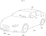
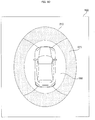
- Figure 1 is a view showing the external appearance of a vehicle having around view cameras according to an embodiment of the present disclosure.
- a vehicle 200 may include a wheels 103FR, 103FL, 103RL, etc., a steering wheel 150, and a plurality of around view cameras 195a, 195b, 195c, and 195d mounted on the vehicle 200.
- a left side view camera 195a and a front view camera 195d are shown merely for the sake of convenience.
- the around view cameras 195a, 195b, 195c, and 195d may be activated to acquire images.
- the images acquired by the cameras may be signal-processed by an around view provision apparatus 100 (see Figure 3A or 3B ).
- the cameras may capture various types of images such as record video images or photograph still images, and the around view provision apparatus as described in various embodiments herein may be applied to these types of images.
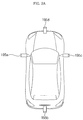
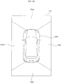
- Figure 2A is a view schematically showing positions of the around view cameras attached to the vehicle shown in Figure 1 and Figure 2B is a view illustrating an around view image based on images captured by the around view cameras of Figure 2A .
- the around view cameras 195a, 195b, 195c, and 195d may be disposed at the left side, the rear, the right side, and the front of the vehicle, respectively.
- the left side view camera 195a and the right side view camera 195c may be disposed in a case (or casing, housing, cover, etc.) surrounding a left side view mirror and a case surrounding a right side view mirror, respectively.
- the rear view camera 195b and the front view camera 195d may be disposed around a trunk switch and at an emblem or around the emblem, respectively.
- a plurality of images captured by the around view cameras 195a, 195b, 195c, and 195d may be transmitted to a processor 170 (see Figure 3A or 3B ) in the vehicle 200.
- the processor 170 may combine the images to generate an around view image.
- Figure 2B shows an example of an around view image 210.
- the around view image 210 may include a first image region 195ai from the left side view camera 195a, a second image region 195bi from the rear view camera 195b, a third image region 195ci from the right side view camera 195c, and a fourth image region 195di from the front view camera 195d.
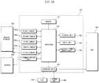
- Figures 3A and 3B are internal block diagrams showing various examples of an around view provision apparatus according to an embodiment of the present disclosure.
- An around view provision apparatus 100 shown in Figures 3A and 3B may combine a plurality of images captured by a plurality of cameras 195a, 195b, 195c, and 195d to generate an around view image.
- the around view provision apparatus 100 may also detect, verify, track and display an object around the vehicle based on a plurality of images captured by the cameras 195a, 195b, 195c, and 195d.
- the around view provision apparatus 100 may include a communication unit 120, an interface unit 130, a memory 140, a processor 170, a display unit 180, an audio interface unit 185, an electric power supply unit 190, and a plurality of around view cameras 195a, 195b, 195c, 195d, and 195e.
- the audio interface unit 185 may include an audio input and/or an audio output devices.
- the communication unit 120 may exchange data with a mobile terminal 600 or a server 500 in a wireless fashion.
- the communication unit 120 may exchange data with a mobile terminal of the driver in a wireless fashion.
- various wireless data communication protocols such as Bluetooth, Wi-Fi, Wi-Fi Direct, and APiX, may be used.
- the communication unit 120 may receive weather information and road traffic state information, such as Transport Protocol Expert Group (TPEG) information, from the mobile terminal 600 or the server 500. On the other hand, the communication unit 120 may transmit real-time traffic information acquired by the around view provision apparatus 100 based on images to the mobile terminal 600 or the server 500.
- TPEG Transport Protocol Expert Group
- the communication unit 120 may transmit real-time traffic information acquired by the around view provision apparatus 100 based on images to the mobile terminal 600 or the server 500.
- a mobile terminal 600 of the user may pair with the around view provision apparatus 100 automatically or by the user executing an application.
- the interface unit 130 may receive vehicle-related data or transmit a signal processed or generated by the processor 170 to the outside. To this end, the interface unit 130 may perform data communication with an electronic control unit (ECU) 770, an audio and video navigation (AVN) apparatus 400, and a sensor unit 760 in the vehicle in a wired communication fashion or a wireless communication fashion.
- ECU electronice control unit
- APN audio and video navigation
- the interface unit 130 may receive map information related to vehicle travel through data communication with the AVN apparatus 400. On the other hand, the interface unit 130 may receive sensor information from the ECU 770 and the sensor unit 760.
- the sensor information may include at least one selected from among vehicle heading information, vehicle position information (GPS information), vehicle angle information, vehicle speed information, vehicle acceleration information, vehicle tilt information, vehicle forward movement/backward movement information, battery information, fuel information, tire information, vehicle lamp information, in-vehicle temperature information, and in-vehicle humidity information.
- vehicle travel information the vehicle heading information, the vehicle position information, the vehicle angle information, the vehicle speed information, and the vehicle tilt information, which are related to vehicle travel.
- the memory 140 may store various data for overall operation of the around view provision apparatus 100, such as programs for processing or control of the processor 170.
- the audio interface unit 185 may convert electric signal received from the processor 170 into an audio signal and output the audio signal.
- the audio interface unit 185 may include a speaker.
- the audio interface unit 185 may output a sound corresponding to an operation of an input unit (not shown), e.g. a button.
- the audio input unit may detect a user's voice.
- the audio input unit may include a microphone. The received voice may be converted into an electric signal, which may be transmitted to the processor 170.
- the processor 170 may control overall operation of each unit in the around view provision apparatus 100.
- the processor 170 may acquire a plurality of images from the cameras 195a, 195b, 195c, and 195d and combine the acquired images to generate an around view image.
- the processor 170 may perform signal processing based on computer vision. For example, the processor 170 may calculate disparity for a view around the vehicle based on the acquired images or the generated around view image, detect an object in the image based on calculated disparity information, and continuously track motion of the object after detection of the object.
- the processor 170 may perform lane detection, adjacent vehicle detection, pedestrian detection, and road surface detection. In addition, the processor 170 may calculate the distance to the detected adjacent vehicle or the detected pedestrian.
- the processor 170 may receive sensor information from the ECU 770 or the sensor unit 760 through the interface unit 130.
- the sensor information may include at least one of vehicle heading information, vehicle position information (GPS information), vehicle angle information, vehicle speed information, vehicle acceleration information, vehicle tilt information, vehicle forward movement/backward movement information, battery information, fuel information, tire information, vehicle lamp information, in-vehicle temperature information, or in-vehicle humidity information.
- the display unit 180 may display the around view image generated by the processor 170. During display of the around view image, the display unit 180 may provide various user interfaces. In addition, the display unit 180 may include a touch sensor to sense a touch input to each user interface.
- the display unit 180 may include a cluster or a head up display (HUD) provided at the inside front of the vehicle.
- the display unit 180 may include a projection module to project an image on the front windshield glass of the vehicle 200.
- the electric power supply unit 190 may supply electric power to the respective components under control of the processor 170.
- electric power from an in-vehicle battery may be supplied to the electric power supply unit 190.
- the cameras 195a, 195b, 195c, and 195d may be cameras to provide an around view image.
- the cameras 195a, 195b, 195c, and 195d may be wide-angle cameras.
- the around view provision apparatus may include additional cameras.
- a camera 195e may be an indoor camera mounted in the vehicle to capture a user, specifically a driver.
- the processor 170 may detect the position of the driver based on an image from the indoor camera, set a region that cannot be observed by a side view mirror or a rear view mirror based on the position of the driver (e.g., blind spot), and control at least one of the cameras to be operated in a first mode, which is referred to as a blind spot detection (BSD) mode, in which at least one of the cameras is moved (e.g., tilted or rotated) to capture the region that cannot be observed by the side view mirror or the rear view mirror.
- BSD blind spot detection
- the around view provision apparatus 100 of Figure 3B may be similar to the around view provision apparatus 100 of Figure 3A except that the around view provision apparatus 100 of Figure 3B may further include an input unit 110 and a sensor unit 198.
- the sensor unit 198 may include ultrasonic sensors, and the sensor unit 198 may be referred to as an ultrasonic sensor unit 198.
- the input unit 110 and the ultrasonic sensor unit 198 may be referred to as an ultrasonic sensor unit 198.
- the input unit 110 may include a plurality of buttons attached around the display unit 180 or a touchscreen disposed on the display unit 180.
- the around view provision apparatus 100 may be powered on through the buttons or the touchscreen such that the around view provision apparatus 100 can be operated.
- various input operations may be performed through the input unit 110.
- the ultrasonic sensor unit 198 may include a plurality of ultrasonic sensors. In a case in which the ultrasonic sensors are mounted in the vehicle, the ultrasonic sensor unit 198 may sense an object around the vehicle based on a difference between transmitted ultrasonic waves and received ultrasonic waves.
- LiDAR Light Detection And Ranging
- Figures 4A and 4B are internal block diagrams showing various examples of the processor shown in Figure 3 and Figure 5 is a series of views showing object detection performed by the processor of Figure 4A and 4B .
- the processor 170 of the around view provision apparatus 100 may include an image preprocessor 410, a disparity calculator 420, a segmentation unit 432, an object detector 434, an object verification unit 436, an object tracking unit 440, and an application unit 450.
- the image preprocessor 410 may receive a plurality of images from the cameras 195a, 195b, 195c, and 195d or a generated around view image and preprocess the plurality of images or the generated around view image.
- the image preprocessor 410 may perform noise reduction, rectification, calibration, color enhancement, color space conversion (CSC), interpolation, camera gain control, or the like, for the plurality of images or the generated around view image. As a result, the image preprocessor 410 may acquire an image that is more vivid than the plurality of images from the cameras 195a, 195b, 195c, and 195d or the generated around view image.
- CSC color space conversion
- the disparity calculator 420 may receive the plurality of images or the generated around view image signal-processed by the image preprocessor 410, sequentially performs stereo matching for the received plural images or the received around view image for a predetermined time, and acquires a disparity map based on the stereo matching. That is, the disparity calculator 420 may acquire disparity information for a view around the vehicle.
- the stereo matching may be performed on a per pixel basis or a per predetermined block basis of the images. Meanwhile, the disparity information may be included in a map showing binocular parallax information as values.
- the segmentation unit 432 may perform segmentation and clustering in the images based on the disparity information from the disparity calculator 420. Specifically, the segmentation unit 432 may segment at least one of the images into a background and a foreground based on the disparity information.
- a region having a predetermined value or less of the disparity information in the disparity map may be calculated as a background and the region may be excluded.
- a foreground may be relatively separated from the image.
- a region having a predetermined value or more of the disparity information in the disparity map may be calculated as a foreground and the region may be extracted. As a result, the foreground may be separated from the image.
- the image may be segmented into the background and the foreground based on the disparity information extracted based on the image. Therefore, signal processing speed and signal processing amount may be reduced during detection of an object.
- the object detector 434 may detect an object based on the image segment from the segmentation unit 432. That is, the object detector 434 may detect an object for at least one of the images based on the disparity information. For example, the object detector 434 may detect an object from a foreground separated from the image by the image segment.
- the object verification unit 436 may classify and verify the separated object.
- the object verification unit 436 may use a recognition method using a neural network, a support vector machine (SVM) method, a recognition method based on AdaBoost using a Haar-like feature, a histogram of oriented gradients (HOG) method, or another appropriate technique.
- SVM support vector machine
- AdaBoost recognition method based on AdaBoost using a Haar-like feature
- HOG histogram of oriented gradients
- the object verification unit 436 may compare the detected object with objects stored in the memory 140 to verify the detected object. For example, the object verification unit 436 may verify an adjacent vehicle, a lane, a road surface, a traffic sign, a dangerous zone, a tunnel, etc. located around the vehicle.
- the object tracking unit 440 may track the verified object. For example, the object tracking unit 440 may verify an object in images which are sequentially acquired, calculate motion or a motion vector of the verified object, and track movement of the object based on the calculated motion or the calculated motion vector. Consequently, the object tracking unit 440 may track an adjacent vehicle, a lane, a road surface, a traffic sign, a dangerous zone, etc. located around the vehicle.
- Figure 4B is an internal block diagram showing another example of the processor 170.
- the processor 170 of Figure 4B is substantially the same as the processor 170 of Figure 4A except that a signal processing sequence of the processor 170 of Figure 4B may be different from that of the processor 170 of Figure 4A .
- a description will be given of only the difference between the processor 170 of Figure 4B and the processor 170 of Figure 4A .
- the object detector 434 may receive a plurality of images or a generated around view image and detect an object in the plural images or the generated around view image. Unlike Figure 4A , the object detector 434 may not detect an object for an image segmented based on disparity information but directly detect an object from the plurality of images or the generated around view image.
- the object verification unit 436 may classify and verify the detected and separated object based on the image segment from the segmentation unit 432 and the object detected by the object detector 434.
- the object verification unit 436 may use a recognition method using a neural network, an SVM method, a recognition method based on AdaBoost using a Haar-like feature, a HOG method, or the like.
- Figure 5 is a series of reference views illustrating an operation of the processor 170 shown in Figure 4A or 4B based on images acquired from first and second frame periods.
- the cameras 195a, 195b, 195c, and 195d may sequentially acquire images FRla and FRlb during the first and and second frame periods.
- the disparity calculator 420 of the processor 170 may receive the images FR1a and FRlb signal-processed by the image preprocessor 410 and may perform stereo matching for the received images FRla and FRlb to acquire a disparity map 520.
- the disparity map 520 may show a disparity between the images FRla and FRlb as levels. When a disparity level is high, the distance to the vehicle may be calculated as being short. When a disparity level is low, on the other hand, the distance to the vehicle may be calculated as being long.
- the disparity map when the disparity map is displayed, the disparity map may be displayed with higher brightness when the disparity level is higher and the disparity map may be displayed with lower brightness when the disparity level is lower.
- Figure 5 shows that in the disparity map 520, first to fourth lanes 528a, 528b, 528c, and 528d may have their own disparity levels and a construction zone 522, a first preceding vehicle 524, and a second preceding vehicle 526 may have their own disparity levels.
- the segmentation unit 432, the object detector 434, and the object verification unit 436 may respectively perform segmentation, object detection, and object verification for at least one of the images FRla and FRlb based on the disparity map 520. Moreover, object detection and object verification for the second image FRlb may be performed using the disparity map 520. That is, object detection and object verification for first to fourth lanes 538a, 538b, 538c, and 538d, a construction zone 532, a first preceding vehicle 534, and a second preceding vehicle 536 in an image 530 may be performed.
- images may be continuously acquired and the object tracking unit 440 may track verified objects.
- Figure 6 is an internal block diagram showing an example of a vehicle according to an embodiment of the present disclosure.
- the vehicle 200 may include an electronic control apparatus 700 for vehicle control.
- the electronic control apparatus 700 may exchange data with the AVN apparatus 400.
- the electronic control apparatus 700 may include an input unit 710, a communication unit 720, a memory 740, a lamp drive unit 751, a steering drive unit 752, a brake drive unit 753, a power source drive unit 754, a sunroof drive unit 755, a suspension drive unit 756, an air conditioning drive unit 757, a window drive unit 758, an airbag drive unit 759, a sensor unit 760, an ECU 770, a display unit 780, an audio output unit 785, an electric power supply unit 790, a plurality of cameras 795.
- the ECU 770 may include a processor. Alternatively, an additional processor to signal-process images from the cameras may be provided in addition to the ECU 770.
- the input unit 710 may include a plurality of buttons or a touchscreen provided in the vehicle 200. Various input operations may be performed through the buttons or the touchscreen.
- the communication unit 720 may exchange data with the mobile terminal 600 or the server 500 in a wireless fashion.
- the communication unit 720 may exchange data with a mobile terminal of the driver in a wireless fashion.
- various wireless data communication protocols such as Bluetooth, Wi-Fi, Wi-Fi Direct, and APiX, may be used.
- the communication unit 720 may receive weather information and road traffic state information, such as TPEG information, from the mobile terminal 600 or the server 500.
- TPEG information road traffic state information
- the communication unit 720 may receive weather information and road traffic state information, such as TPEG information, from the mobile terminal 600 or the server 500.
- a mobile terminal 600 of the user may pair with the electronic control apparatus 700 automatically or by the user executing an application.
- the memory 740 may store various data for overall operation of the electronic control apparatus 700, such as programs for processing or control of the ECU 770.
- the lamp drive unit 751 may control turn on/turn off of lamps provided inside and outside the vehicle.
- the lamp drive unit 751 may control intensity, direction, etc. of light emitted from each lamp.
- the lamp drive unit 751 may control a direction indicating lamp, a brake lamp, etc.
- the steering drive unit 752 may electronically control a steering apparatus (not shown) in the vehicle 200. Consequently, the steering drive unit 752 may change a heading of the vehicle.
- the brake drive unit 753 may electronically control a brake apparatus in the vehicle 200.
- the brake drive unit 753 may control an operation of a brake mounted at each wheel to reduce speed of the vehicle 200.
- the brake drive unit 753 may differently control operations of brakes mounted at left wheels and right wheels to adjust the heading of the vehicle 200 to the left or the right.
- the power source drive unit 754 may electronically control a power source in the vehicle 200.
- the power source drive unit 754 may electronically control the engine. Consequently, the power source drive unit 754 may control output torque of the engine.
- the power source drive unit 754 may control the motor. Consequently, the power source drive unit 754 may control rotational speed and torque of the motor.
- the sunroof drive unit 755 may electronically control a sunroof apparatus in the vehicle 200.
- the sunroof drive unit 755 may control a sunroof to be opened or closed.
- the suspension drive unit 756 may electronically control a suspension apparatus in the vehicle 200. For example, when a road surface is uneven, the suspension drive unit 756 may control the suspension apparatus to reduce vibration of the vehicle 200.
- the air conditioning drive unit 757 may electronically control an air conditioner in the vehicle 200. For example, when the internal temperature of the vehicle is high, the air conditioning drive unit 757 may control the air conditioner to supply cool air into the vehicle.
- the window drive unit 758 may electronically control a window apparatus in the vehicle 200.
- the window drive unit 758 may control left and right side windows of the vehicle to be opened or closed.
- the airbag drive unit 759 may electronically control an airbag apparatus in the vehicle 200.
- the airbag drive unit 759 may control an airbag to deploy in a dangerous situation.
- the sensor unit 760 may sense a signal related to travel of the vehicle 200.
- the sensor unit 760 may include a heading sensor, a yaw sensor, a gyro sensor, a position module, a vehicle forward movement/backward movement sensor, a wheel sensor, a vehicle speed sensor, a vehicle body tilt sensor, a battery sensor, a fuel sensor, a tire sensor, a steering sensor, an in-vehicle temperature sensor, an in-vehicle humidity sensor or another appropriate type of sensor.
- the sensor unit 760 may acquire a sensing signal for vehicle heading information, vehicle position information (GPS information), vehicle angle information, vehicle speed information, vehicle acceleration information, vehicle tilt information, vehicle forward movement/backward movement information, battery information, fuel information, tire information, vehicle lamp information, in-vehicle temperature information, in-vehicle humidity information, and the like.
- the sensor unit 760 may further include an engine speed sensor, an air flow sensor (AFS), an intake air temperature sensor (ATS), a water temperature sensor (WTS), a throttle position sensor (TPS), a top dead center (TDC) sensor, and a crank angle sensor (CAS).
- AFS air flow sensor
- ATS intake air temperature sensor
- WTS water temperature sensor
- TPS throttle position sensor
- TDC top dead center
- CAS crank angle sensor
- the ECU 770 may control overall operation of each unit in the electronic control apparatus 700.
- the ECU 770 may perform a specific operation based on an input through the input unit 710, receive and transmit a signal sensed by the sensor unit 760 to the around view provision apparatus 100, receive map information from the AVN apparatus 400, or control operations of the respective drive units 751, 752, 753, 754, and 756.
- the ECU 770 may receive weather information and road traffic state information, such as TPEG information, from the communication unit 720.
- the ECU 770 may combine a plurality of images received from the plurality of cameras 795 to generate an around view image.
- the ECU 770 may generate an around view image.
- the display unit 780 may display the generated around view image.
- the display unit 180 may provide various user interfaces in addition to the around view image.
- the display unit 780 may include a cluster or an HUD provided at the inside front of the vehicle.
- the display unit 180 may include a projection module to project an image on the front windshield glass of the vehicle 200.
- the display unit 780 may include a touchscreen to allow input by tapping on the screen.
- the audio unit 785 may convert an electric signal received from the ECU 770 into an audio signal and output the audio signal.
- the audio unit 785 may include a speaker.
- the audio unit 785 may output a sound corresponding to an operation of the input unit 710, e.g. a button.
- the audio unit 785 may also include a microphone to receive sound.
- the audio unit 785 may include an audio input unit and an audio output unit.
- the electric power supply unit 790 may supply electric power to the respective components under control of the ECU 770.
- electric power from an in-vehicle battery may be supplied to the electric power supply unit 790.
- the plurality of cameras 795 may be used to provide an around view image.
- the plurality of cameras 795 may include four cameras as shown in Figure 2A .
- a plurality of around view cameras 195a, 195b, 195c, and 195d may be disposed at the left side, the rear, the right side, and the front of the vehicle, respectively.
- a plurality of images captured by the plurality of cameras 795 may be transmitted to the ECU 770 or an additional processor.
- a partial region of the around view image may be distorted depending upon disposition of the around view cameras 195a, 195b, 195c, and 195d in the vehicle.
- the present disclosure proposes a method of reducing such distortion, which will hereinafter be described with reference to Figures 7 to 14 .
- Figure 7 is a flowchart of a method of operating the around view provision apparatus according to the embodiment of the present disclosure and Figures 8A to 14 are reference views illustrating the method of operating the around view provision apparatus of Figure 7 .
- the processor 170 of the around view provision apparatus 100 may receive images captured by the around view cameras 195a, 195b, 195c, and 195d, in Step S710.
- the around view cameras 195a, 195b, 195c, and 195d may be disposed at the left side, the rear, the right side, and the front of the vehicle, respectively.
- the left side view camera 195a and the right side view camera 195c may be disposed in the case surrounding the left side view mirror and the case surrounding the right side view mirror, respectively.
- the rear view camera 195b and the front view camera 195d may be disposed, for example, around the trunk switch and at the emblem or around the emblem, respectively.
- the images captured by the around view cameras 195a, 195b, 195c, and 195d may be transmitted to the processor 170 in the vehicle 200.
- the processor 170 of the around view provision apparatus 100 may project the received images on a first solid projection surface to generate an around view image and may project a partial region of the around view image on a second solid projection surface, to generate a partially calibrated around view image, in Step S720.
- the first and second solid projection surfaces may be virtual surfaces having prescribed contours onto which the captured images may be projected.
- the processor 170 of the around view provision apparatus 100 may control the generated around view image to be displayed on the display unit 180, in Step S730.
- the processor 170 may perform signal processing to a top view or a bird's eye view based on the vehicle using the images captured by the around view cameras 195a, 195b, 195c, and 195d.
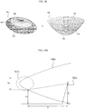
- Figure 8A shows, by way of example, an oval solid projection surface 800 as the first solid projection surface.
- the processor 170 may project images on the oval solid projection surface 800 as shown in Figure 8A and perform nonlinear scaling for regions in the respective images using a scaling factor corresponding to the projection surface.
- the processor 170 may combine the nonlinearly scaled images to generate an around view image.
- Figure 8B shows, by way of example, an around view image 810 acquired by projecting images on the oval solid projection surface 800.
- regions spaced a predetermined distance or more from a vehicle image 203 may be distorted due to excessive scaling, particularly excessive downscaling.
- an inner region 801 adjacent to the vehicle image 203 and an outer region 802 distant from the vehicle image 203 may be partitioned from each other by an oval line 809.
- distortion may occur at a boundary region 815 between the images from the left side view camera and the rear view camera in the outer region 802 which is distant from the vehicle image 203.
- the image boundary region 815 may be distorted due to excessive downscaling and may appear as if the size of the image boundary region 815 is smaller than the actual size.
- the size of the image boundary region 815 may be much smaller than that of the vehicle image 203.
- the acquired around view image 810 displayed through the display unit 180 may appear to have unnatural perspective to a driver or a user viewing the around view image 180.
- the processor 170 it may be necessary for the processor 170 to control the above regions to be scaled with different magnifying power using a second solid projection surface having a different contour from the first solid projection surface.
- Figure 9A shows that images are projected on an upper region, e.g., a first region 806, of the oval solid projection surface 800 while partial regions of the respective images are projected on a lower region, e.g., a second region 907, of a conical oval solid projection surface 900.
- the upper region 806 and a lower region 807 of the oval solid projection surface 800 are partitioned from each other by a first curved line 805.
- An upper region 906 and the lower region 907 of the conical oval solid projection surface 900 are partitioned from each other by a second curved line 905.
- the processor 170 may scale the lower region 907 of the conical oval solid projection surface 900 with magnifying power different from that in scaling of the oval solid projection surface 800. That is, the processor 170 may not scale down the lower region 907 but may scale up the lower region 907.
- the processor 170 may not scale down the lower region 907 but may scale up the lower region 907.
- Figure 9B shows, by way of example, an around view image 210.
- the around view image 210 is similar to the around view image of Figure 2B , but may include distortions in the images as previously described.
- a distorted region 970' may be a partial region (e.g., outer region or regions containing objects), and distortions in this region may be reduced as described hereinafter.
- the around view image 210 may include a first image region 195ai from the left side view camera 195a, a second image region 195bi from the rear view camera 195b, a third image region 195ci from the right side view camera 195c, and a fourth image region 195di from the front view camera 195d.
- the processor 170 may project the region of the around view image corresponding to the selection input on the second solid projection surface to generate a partially calibrated around view image.
- Figure 9C(a) shows, by way of example, that, when the around view image 810 before calibration is displayed on the display unit 180, the outer region 802 of the around view image 810 before calibration may be selected by a touch input.
- the display unit 180 is a touchscreen or a touch display device to sense a touch input
- the processor 170 may change scaling of the corresponding region in response to the sensed touch input.
- the processor 170 may control the corresponding region to be projected on the second solid projection surface.
- the processor 170 may project the selected region on the second solid projection surface to generate a partially calibrated around view image.
- Figure 9C(b) shows, by way of example, that the around view image 810 after calibration may be displayed on the display unit 180. As shown in Figure 9C(b) , an around view image, a desired region of which has been calibrated, may be generated and displayed. As a result, user convenience may be improved.
- the processor 170 may control the partially calibrated around view image to be displayed on the display unit 180. At this time, the processor 170 may control the partial region to be displayed in a highlighted fashion or an object indicating the partial region to be displayed in an overlapping fashion on the partially calibrated around view image displayed through the display unit 180.
- Figure 9D shows, by way of example, that the partially calibrated around view image may be displayed on the display unit 180 while a partial region 970 is highlighted differently from other regions.
- the partial region 970 may be highlighted by changing brightness, colors, or the like. Consequently, it may be possible for the driver or the user to immediately recognize the partial region.
- the respective images may be projected on the lower region, e.g., the second region 807, of the oval solid projection surface 800 while partial regions of the respective images are projected on an upper region, e.g., a first region 906, of the conical oval solid projection surface 900 as illustrated in Figure 9E .
- Figures 10A to 11B show various examples of preventing distortion of a partial region based on the first solid projection surface and the second solid projection surface.
- Figure 10A shows, by way of example, that when a region 1015 positioned at a second height h2 and spaced from the left side view camera 195a positioned at a first height h1 by a first distance D1 is projected on a first oval solid projection surface 1005, the region 1015 may be distorted.
- the distorted region 1015 may have a distortion height h3.
- the region 1015 positioned at a lower height than the left side view camera 195a is projected on the first oval solid projection surface 1005, the region 1015 may be distorted.
- the processor 170 may control the region 1015 positioned at the second height h2 to be projected on a second parabolic solid projection surface 1025, not the first oval solid projection surface 1005. As a result, it is possible to generate an around view image with reduced distortion of the region 1015.
- a convex region of the first solid projection surface 1005 may be different in direction from a convex region of the second solid projection surface 1025.
- the processor 170 may generate a partially calibrated around view image using different curvatures of the first solid projection surface and the second solid projection surface, different directions of the convex region of the first solid projection surface and the convex region of the second solid projection surface, or a combination thereof.
- the processor 170 may set the size of the partial region of the around view image to be increased. As a result, distortion of the partial region of the around view image may be reduced.
- the processor 170 may project a region corresponding to the specific object on the second solid projection surface to generate a partially calibrated around view image.
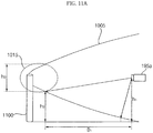
- Figure 11A shows, by way of example, that a specific object 1100 may be located at the region 1015 positioned at the second height h2 and spaced from the left side view camera 195a positioned at the first height h1 by the first distance D1 and, when the region 1015 is projected on the first oval solid projection surface 1005, the region 1015 may be distorted.
- the distorted region 1015 may have a distortion height h3.
- the specific object 1100 may be, for example, a post, a traffic sign, or another appropriate type of object in the vicinity of the vehicle.
- the region 1015 positioned at a lower height than the left side view camera 195a is projected on the first oval solid projection surface 1005
- the region 1015 may be distorted.
- the processor 170 may control the region 1015 and the specific object 1100 positioned at the second height h2 to be projected on the first oval solid projection surface 1005 and the second parabolic solid projection surface 1025.
- the processor 170 may change at least one of a size or a position of at least a partial region of the second solid projection surface in response to a travel direction of the vehicle, which will hereinafter be described in detail with reference to Figures 12A to 12C .
- Figure 12A illustrates, by way of example, that the vehicle 200 may move backward in a clockwise direction.
- the vehicle may move more in a right side rear direction at a second point in time T2 than at a first point in time T1 and may move more in a left side rear direction at a third point in time T3 than at the second point of time.
- the processor 170 may change at least one of the size or the position of at least a partial region of the second solid projection surface in response to the travel direction of the vehicle. That is, at the first point of time T1, the processor 170 may project the respective images from the cameras 195a, 195b, 195c, and 195d on the upper region, e.g., the first region 806, of the oval solid projection surface 800 while partial regions of the respective images are projected on the lower region, e.g., the second region 907, of the conical oval solid projection surface 900 as shown in Figure 12B or 9A .
- the vehicle may have moved in the right side rear direction. Consequently, the processor 170 may project the respective images from the cameras 195a, 195b, 195c, and 195d on an right side upper region 1206 of the oval solid projection surface 800 generated according to movement of a curved line 1205 to the right, while partial regions of the respective images are projected on a left side lower region 1217 of the conical oval solid projection surface 900. As a result, it may be possible to generate an around view image with reduced distortion corresponding to the travel direction of the vehicle.
- the processor 170 may project the respective images on the upper region, e.g., the first region 806, of the oval solid projection surface 800, while partial regions of the respective images are projected on the lower region, e.g., the second region 907, of the conical oval solid projection surface 900 in the same manner as at the first point of time T1.
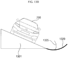
- the processor 170 may change at least one of a tilt or an angle of at least one selected from between the first solid projection surface and the solid projection surface in response to the tilt of the vehicle, which will hereinafter be described in detail with reference to Figures 13A and 13B .
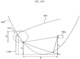
- Figure 13A shows, by way of example, that the vehicle 200 may be located on an upward slope 1300.
- the processor 170 may generate an around view image with reduced distortion of a specific region behind the vehicle using a second projection surface 1315 similar to a first projection surface 1310 but having a different curvature than the first projection surface 1310.
- the processor 170 may adjust the tilt or the angle of the second projection surface 1315 to generate an around view image.
- Figure 13B illustrates, by way of example, a case in which the vehicle 200 is positioned on a left incline 1301, e.g., sideways on an incline with the left side of the vehicle positioned downhill.
- the processor 170 may generate an around view image with reduced distortion of a specific region at the left side of the vehicle using a second projection surface 1325 similar to a first projection surface 1320, but having a different curvature from the first projection surface 1320.
- the processor 170 may adjust the tilt or the angle of the second projection surface 1325 to generate an around view image.
- the processor 170 may select a second solid projection surface among a plurality of second solid projection surfaces based on a detected inclination of the vehicle or a road surface.
- the around view image may include a plurality of regions that correspond to an object having a prescribed inclination, and each of the plurality of regions of the around view image may be generated using a different solid projection surface. Accordingly, various tilt or angle of inclination of the vehicle or road surface may be accounted for to more accurately remove the distortions caused by the inclination.
- the processor 170 may continuously process captured images as the position of the vehicle changes to update the displayed around view image. Also, it may be possible
- Figure 14 illustrates, by way of example, a plurality of ultrasonic sensors provided on the vehicle for use in generating an around view image.
- the vehicle 200 includes a plurality of ultrasonic sensors 198
- the processor 170 may project a region containing the object of the around view image on the second projection surface to generate a partially calibrated around view image.
- the vehicle 200 may include a plurality of ultrasonic sensors 198a to 198j to sense approach of a specific object.
- the first to third ultrasonic sensors 198a, 198b, and 198c may be attached to the front end of the vehicle
- the fourth and fifth ultrasonic sensors 198d and 198e may be attached to opposite sides of the front part of the vehicle
- the sixth and seventh ultrasonic sensors 198f and 198g may be attached to opposite sides of the rear part of the vehicle
- the eighth to tenth ultrasonic sensors 198h, 198i, and 198j may be attached to the rear end of the vehicle.
- the present disclosure is not limited to the number and positions of the ultrasonic sensors, but may include more or less ultrasonic sensors positioned at various locations on the vehicle.
- a specific object 1100 located at the left side rear of the vehicle may be sensed by the sixth ultrasonic sensor 198f.
- the processor 170 may control the specific object 1100 to be projected on the second solid projection surface, not the first solid projection surface.
- the processor 170 may process the images captured by the left side view camera 195a to reduce or remove distortions.
- the detected specific object 1100 may be the specific object 1100 as previously described with regard to Figure 11A .
- the region 1015 is located at a region 1015 positioned at a second height h2 and spaced from the left side view camera 195a positioned at a first height h1 by a first distance D1 and, in a case in which the region 1015 is projected on a first solid projection surface 1005, the region 1015 is distorted.
- the distorted region 1015 may have a distortion height h3.
- the specific object 1100 may be, for example, a post, a traffic sign, or the like.
- the processor 170 may control the region 1015 and the specific object 1100 positioned at the second height h2 to be projected on a second parabolic solid projection surface 1025.
- the processing of the captured image may continuously be performed as the vehicle moves relative to the specific object 110, and the display of the around view image may be continuously be updated. As a result, it may be possible to generate an around view image with reduced distortion of the region 1015 and the detected specific object 1100.
- the operation method of the around view provision apparatus and the vehicle according to the present disclosure may be implemented as code that can be written on a processor-readable recording medium and thus read by a processor provided in the around view provision apparatus or the vehicle.
- the processor-readable recording medium may be any type of recording device in which data may be stored in a processor-readable manner.
- the processor-readable recording medium may include, for example, a read only memory (ROM), a random access memory (RAM), a compact disc read only memory (CD-ROM), a magnetic tape, a floppy disc, and an optical data storage device and may be implemented in the form of a carrier wave transmitted over the Internet.
- the processor-readable recording medium can be distributed over a plurality of computer systems connected to a network such that processor-readable code is written thereto and executed therefrom in a decentralized manner.
- an around view provision apparatus is provided. It is an object of the present disclosure to provide an around view provision apparatus that is capable of reducing distortion of an around view image and a vehicle including the same.
- an around view provision apparatus including first to fourth cameras mounted at a vehicle and a processor to project images from the first to fourth cameras on a first solid projection surface so as to generate an around view image and to project a partial region of the around view image on a second solid projection surface different from the first solid projection surface so as to generate a partially calibrated around view image.
- the around view provision apparatus and the vehicle may each further include at least one ultrasonic sensor mounted at the vehicle, wherein, when a specific object approaches within a predetermined distance from the vehicle based on the at least one ultrasonic sensor, the processor may project a region containing the object of the around view image on the second solid projection surface to generate the partially calibrated around view image. Consequently, it may be possible to generate a more accurate around view image.
- the processor may project a region of the around view image corresponding to a selection input on the second solid projection surface to generate the partially calibrated around view image, thereby improving user convenience.
- an around view provision apparatus may include first to fourth cameras mounted at a vehicle and a processor to generate an around view image based on images from the first to fourth cameras using a first scaling factor corresponding to a first solid shape and to generate a partially calibrated around view image based on a partial region of the around view image using a scaling factor corresponding to a second solid shape different from the first solid shape.
- a vehicle may include a steering drive unit to drive a steering apparatus, a brake drive unit to drive a brake apparatus, a power source drive unit to drive a power source, first to fourth cameras mounted at the vehicle, and a processor to project images from the first to fourth cameras on a first solid projection surface so as to generate an around view image and to project a partial region of the around view image on a second solid projection surface different from the first solid projection surface so as to generate a partially calibrated around view image.
- any reference in this specification to "one embodiment,” “an embodiment,” “example embodiment,” etc. means that a particular feature, structure, or characteristic described in connection with the embodiment is included in at least one embodiment of the invention.
- the appearances of such phrases in various places in the specification are not necessarily all referring to the same embodiment.
Description
- The present disclosure relates to an around view provision apparatus and a vehicle including the same and, more particularly, to an around view provision apparatus that is capable of reducing distortion of an around view image and a vehicle including the same.
- Around view provision apparatuses and vehicles including the same are known.
EP 2 723 069 discloses a vehicle surrounding-area monitoring apparatus that, when recognizing an obstacle, allows for easy determination of the positional relationship between the obstacle and scenery included in a video image of the area surrounding the vehicle, generates a narrow view-field region that is a part of the video image as a notable video image, and if an obstacle region that is a region of the recognized obstacle in the video image is located outside of the narrow view-field region and if the obstacle region is contained in an image region that is partially overlapping with the narrow view-field region and is a part of the video image, generates the image region as a notable obstacle image so as to generate a surrounding-area monitoring display image comprised of the notable video image and the notable obstacle image. However, they suffer from various disadvantages. - The embodiments will be described in detail with reference to the following drawings in which like reference numerals refer to like elements wherein:
-
Figure 1 is a view showing the external appearance of a vehicle having around view cameras according to an embodiment of the present disclosure; -
Figure 2A is a view schematically showing positions of the around view cameras attached to the vehicle shown inFigure 1 ; -
Figure 2B is a view showing an around view image based on images captured by the around view cameras ofFigure 2A ; -
Figures 3A and3B are internal block diagrams showing various examples of an around view provision apparatus according to an embodiment of the present disclosure; -
Figures 4A and 4B are internal block diagrams showing various examples of a processor shown inFigure 3 ; -
Figure 5 is a series of views showing object detection performed by the processor ofFigures 4A and 4B ; -
Figure 6 is an internal block diagram showing an example of a vehicle according to an embodiment of the present disclosure; -
Figure 7 is a flowchart showing an operation method of the around view provision apparatus according to the embodiment of the present disclosure; and -
Figures 8A to 14 are reference views illustrating the operation method of the around view provision apparatus shown inFigure 7 . - Exemplary embodiments of the present disclosure will be described with reference to the attached drawings.
- The terms "module" and "unit," when attached to the names of components are used herein to help the understanding of the components and thus they should not be considered as having specific meanings or roles. Accordingly, the terms "module" and "unit" may be used interchangeably.
- Broadly, a vehicle is a device that allows a driver to move in a desired direction. A representative example of the vehicle may be a car. In order to improve convenience of a user who uses the vehicle, the vehicle may be equipped with various sensors and electronic devices. In particular, various devices to improve driving convenience of the user have been developed. For example, an image captured by a rear view camera may be provided when moving the vehicle backward or when parking the vehicle.
- A vehicle as described in this specification may include a car, a motorcycle, or another appropriate type of vehicle. Hereinafter, a description will be given based on a car merely for sake of convenience.
- It should be appreciated, however, that a vehicle as described in this disclosure may include various types of transportation devices, including but not limited to, a vehicle having an engine as a power source, a hybrid vehicle having an engine and an electric motor as a power source, an electric vehicle having an electric motor as a power source, or the like.
- Meanwhile, an around view provision apparatus as described in this specification may be an apparatus that includes a plurality of cameras and which combines a plurality of images captured by the cameras to generate an around view image. In particular, the around view provision apparatus may be a vehicle-based apparatus that provides a top view or a bird's eye view. It is one object of the present disclosure to provide an around view provision apparatus that is capable of reducing distortion of an around view image and a vehicle including the same. Hereinafter, a description will be given of various embodiments of an around view provision apparatus according to the present disclosure and a vehicle including the same.
-
Figure 1 is a view showing the external appearance of a vehicle having around view cameras according to an embodiment of the present disclosure. - A
vehicle 200 may include a wheels 103FR, 103FL, 103RL, etc., asteering wheel 150, and a plurality ofaround view cameras vehicle 200. InFigure 1 , only a leftside view camera 195a and afront view camera 195d are shown merely for the sake of convenience. - When the vehicle moves forward at a predetermined speed or less or when the vehicle moves backward, the around
view cameras Figure 3A or3B ). Moreover, the cameras may capture various types of images such as record video images or photograph still images, and the around view provision apparatus as described in various embodiments herein may be applied to these types of images. -
Figure 2A is a view schematically showing positions of the around view cameras attached to the vehicle shown inFigure 1 andFigure 2B is a view illustrating an around view image based on images captured by the around view cameras ofFigure 2A . - Referring first to
Figure 2A , the aroundview cameras side view camera 195a and the rightside view camera 195c may be disposed in a case (or casing, housing, cover, etc.) surrounding a left side view mirror and a case surrounding a right side view mirror, respectively. On the other hand, therear view camera 195b and thefront view camera 195d may be disposed around a trunk switch and at an emblem or around the emblem, respectively. - A plurality of images captured by the around
view cameras Figure 3A or3B ) in thevehicle 200. The processor 170 (seeFigure 3A or3B ) may combine the images to generate an around view image. -
Figure 2B shows an example of an aroundview image 210. The aroundview image 210 may include a first image region 195ai from the leftside view camera 195a, a second image region 195bi from therear view camera 195b, a third image region 195ci from the rightside view camera 195c, and a fourth image region 195di from thefront view camera 195d. -
Figures 3A and3B are internal block diagrams showing various examples of an around view provision apparatus according to an embodiment of the present disclosure. - An around
view provision apparatus 100 shown inFigures 3A and3B may combine a plurality of images captured by a plurality ofcameras view provision apparatus 100 may also detect, verify, track and display an object around the vehicle based on a plurality of images captured by thecameras - Referring first to
Figure 3A , the aroundview provision apparatus 100 may include acommunication unit 120, aninterface unit 130, amemory 140, aprocessor 170, adisplay unit 180, anaudio interface unit 185, an electricpower supply unit 190, and a plurality ofaround view cameras audio interface unit 185 may include an audio input and/or an audio output devices. - The
communication unit 120 may exchange data with amobile terminal 600 or aserver 500 in a wireless fashion. In particular, thecommunication unit 120 may exchange data with a mobile terminal of the driver in a wireless fashion. To this end, various wireless data communication protocols, such as Bluetooth, Wi-Fi, Wi-Fi Direct, and APiX, may be used. - The
communication unit 120 may receive weather information and road traffic state information, such as Transport Protocol Expert Group (TPEG) information, from themobile terminal 600 or theserver 500. On the other hand, thecommunication unit 120 may transmit real-time traffic information acquired by the aroundview provision apparatus 100 based on images to themobile terminal 600 or theserver 500. When a user gets into the vehicle, amobile terminal 600 of the user may pair with the aroundview provision apparatus 100 automatically or by the user executing an application. - The
interface unit 130 may receive vehicle-related data or transmit a signal processed or generated by theprocessor 170 to the outside. To this end, theinterface unit 130 may perform data communication with an electronic control unit (ECU) 770, an audio and video navigation (AVN)apparatus 400, and asensor unit 760 in the vehicle in a wired communication fashion or a wireless communication fashion. - The
interface unit 130 may receive map information related to vehicle travel through data communication with the AVNapparatus 400. On the other hand, theinterface unit 130 may receive sensor information from theECU 770 and thesensor unit 760. - The sensor information may include at least one selected from among vehicle heading information, vehicle position information (GPS information), vehicle angle information, vehicle speed information, vehicle acceleration information, vehicle tilt information, vehicle forward movement/backward movement information, battery information, fuel information, tire information, vehicle lamp information, in-vehicle temperature information, and in-vehicle humidity information.
- Of the above-specified sensor information, the vehicle heading information, the vehicle position information, the vehicle angle information, the vehicle speed information, and the vehicle tilt information, which are related to vehicle travel, may be referred to as vehicle travel information.
- The
memory 140 may store various data for overall operation of the aroundview provision apparatus 100, such as programs for processing or control of theprocessor 170. - The
audio interface unit 185 may convert electric signal received from theprocessor 170 into an audio signal and output the audio signal. To this end, theaudio interface unit 185 may include a speaker. Theaudio interface unit 185 may output a sound corresponding to an operation of an input unit (not shown), e.g. a button. The audio input unit may detect a user's voice. To this end, the audio input unit may include a microphone. The received voice may be converted into an electric signal, which may be transmitted to theprocessor 170. - The
processor 170 may control overall operation of each unit in the aroundview provision apparatus 100. In particular, theprocessor 170 may acquire a plurality of images from thecameras - On the other hand, the
processor 170 may perform signal processing based on computer vision. For example, theprocessor 170 may calculate disparity for a view around the vehicle based on the acquired images or the generated around view image, detect an object in the image based on calculated disparity information, and continuously track motion of the object after detection of the object. - In particular, during detection of the object, the
processor 170 may perform lane detection, adjacent vehicle detection, pedestrian detection, and road surface detection. In addition, theprocessor 170 may calculate the distance to the detected adjacent vehicle or the detected pedestrian. - On the other hand, the
processor 170 may receive sensor information from theECU 770 or thesensor unit 760 through theinterface unit 130. The sensor information may include at least one of vehicle heading information, vehicle position information (GPS information), vehicle angle information, vehicle speed information, vehicle acceleration information, vehicle tilt information, vehicle forward movement/backward movement information, battery information, fuel information, tire information, vehicle lamp information, in-vehicle temperature information, or in-vehicle humidity information. - The
display unit 180 may display the around view image generated by theprocessor 170. During display of the around view image, thedisplay unit 180 may provide various user interfaces. In addition, thedisplay unit 180 may include a touch sensor to sense a touch input to each user interface. - Meanwhile, the
display unit 180 may include a cluster or a head up display (HUD) provided at the inside front of the vehicle. In a case in which thedisplay unit 180 is the HUD, thedisplay unit 180 may include a projection module to project an image on the front windshield glass of thevehicle 200. - The electric
power supply unit 190 may supply electric power to the respective components under control of theprocessor 170. In particular, electric power from an in-vehicle battery may be supplied to the electricpower supply unit 190. - The
cameras cameras camera 195e may be an indoor camera mounted in the vehicle to capture a user, specifically a driver. Theprocessor 170 may detect the position of the driver based on an image from the indoor camera, set a region that cannot be observed by a side view mirror or a rear view mirror based on the position of the driver (e.g., blind spot), and control at least one of the cameras to be operated in a first mode, which is referred to as a blind spot detection (BSD) mode, in which at least one of the cameras is moved (e.g., tilted or rotated) to capture the region that cannot be observed by the side view mirror or the rear view mirror. - Referring now to
Figure 3B , the aroundview provision apparatus 100 ofFigure 3B may be similar to the aroundview provision apparatus 100 ofFigure 3A except that the aroundview provision apparatus 100 ofFigure 3B may further include aninput unit 110 and asensor unit 198. In a non-limiting example, thesensor unit 198 may include ultrasonic sensors, and thesensor unit 198 may be referred to as anultrasonic sensor unit 198. Hereinafter, for sake of brevity, a description will be given of only theinput unit 110 and theultrasonic sensor unit 198. - The
input unit 110 may include a plurality of buttons attached around thedisplay unit 180 or a touchscreen disposed on thedisplay unit 180. The aroundview provision apparatus 100 may be powered on through the buttons or the touchscreen such that the aroundview provision apparatus 100 can be operated. On the other hand, various input operations may be performed through theinput unit 110. - The
ultrasonic sensor unit 198 may include a plurality of ultrasonic sensors. In a case in which the ultrasonic sensors are mounted in the vehicle, theultrasonic sensor unit 198 may sense an object around the vehicle based on a difference between transmitted ultrasonic waves and received ultrasonic waves. - Unlike
Figure 3B , on the other hand, Light Detection And Ranging (LiDAR) (not shown) may be provided instead of theultrasonic sensor unit 198. Alternatively, both theultrasonic sensor unit 198 and the LiDAR may be provided. -
Figures 4A and 4B are internal block diagrams showing various examples of the processor shown inFigure 3 andFigure 5 is a series of views showing object detection performed by the processor ofFigure 4A and 4B . - Referring first to
Figure 4A , which is an internal block diagram showing an example of theprocessor 170, theprocessor 170 of the aroundview provision apparatus 100 may include animage preprocessor 410, adisparity calculator 420, asegmentation unit 432, anobject detector 434, anobject verification unit 436, anobject tracking unit 440, and anapplication unit 450. - The
image preprocessor 410 may receive a plurality of images from thecameras - Specifically, the
image preprocessor 410 may perform noise reduction, rectification, calibration, color enhancement, color space conversion (CSC), interpolation, camera gain control, or the like, for the plurality of images or the generated around view image. As a result, theimage preprocessor 410 may acquire an image that is more vivid than the plurality of images from thecameras - The
disparity calculator 420 may receive the plurality of images or the generated around view image signal-processed by theimage preprocessor 410, sequentially performs stereo matching for the received plural images or the received around view image for a predetermined time, and acquires a disparity map based on the stereo matching. That is, thedisparity calculator 420 may acquire disparity information for a view around the vehicle. The stereo matching may be performed on a per pixel basis or a per predetermined block basis of the images. Meanwhile, the disparity information may be included in a map showing binocular parallax information as values. - The
segmentation unit 432 may perform segmentation and clustering in the images based on the disparity information from thedisparity calculator 420. Specifically, thesegmentation unit 432 may segment at least one of the images into a background and a foreground based on the disparity information. - For example, a region having a predetermined value or less of the disparity information in the disparity map may be calculated as a background and the region may be excluded. As a result, a foreground may be relatively separated from the image. In another example, a region having a predetermined value or more of the disparity information in the disparity map may be calculated as a foreground and the region may be extracted. As a result, the foreground may be separated from the image.
- As described above, the image may be segmented into the background and the foreground based on the disparity information extracted based on the image. Therefore, signal processing speed and signal processing amount may be reduced during detection of an object.
- The
object detector 434 may detect an object based on the image segment from thesegmentation unit 432. That is, theobject detector 434 may detect an object for at least one of the images based on the disparity information. For example, theobject detector 434 may detect an object from a foreground separated from the image by the image segment. - Subsequently, the
object verification unit 436 may classify and verify the separated object. To this end, theobject verification unit 436 may use a recognition method using a neural network, a support vector machine (SVM) method, a recognition method based on AdaBoost using a Haar-like feature, a histogram of oriented gradients (HOG) method, or another appropriate technique. - On the other hand, the
object verification unit 436 may compare the detected object with objects stored in thememory 140 to verify the detected object. For example, theobject verification unit 436 may verify an adjacent vehicle, a lane, a road surface, a traffic sign, a dangerous zone, a tunnel, etc. located around the vehicle. - The
object tracking unit 440 may track the verified object. For example, theobject tracking unit 440 may verify an object in images which are sequentially acquired, calculate motion or a motion vector of the verified object, and track movement of the object based on the calculated motion or the calculated motion vector. Consequently, theobject tracking unit 440 may track an adjacent vehicle, a lane, a road surface, a traffic sign, a dangerous zone, etc. located around the vehicle. -
Figure 4B is an internal block diagram showing another example of theprocessor 170. Theprocessor 170 ofFigure 4B is substantially the same as theprocessor 170 ofFigure 4A except that a signal processing sequence of theprocessor 170 ofFigure 4B may be different from that of theprocessor 170 ofFigure 4A . Hereinafter, a description will be given of only the difference between theprocessor 170 ofFigure 4B and theprocessor 170 ofFigure 4A . - The
object detector 434 may receive a plurality of images or a generated around view image and detect an object in the plural images or the generated around view image. UnlikeFigure 4A , theobject detector 434 may not detect an object for an image segmented based on disparity information but directly detect an object from the plurality of images or the generated around view image. - Subsequently, the
object verification unit 436 may classify and verify the detected and separated object based on the image segment from thesegmentation unit 432 and the object detected by theobject detector 434. To this end, theobject verification unit 436 may use a recognition method using a neural network, an SVM method, a recognition method based on AdaBoost using a Haar-like feature, a HOG method, or the like. -
Figure 5 is a series of reference views illustrating an operation of theprocessor 170 shown inFigure 4A or 4B based on images acquired from first and second frame periods. Thecameras - The
disparity calculator 420 of theprocessor 170 may receive the images FR1a and FRlb signal-processed by theimage preprocessor 410 and may perform stereo matching for the received images FRla and FRlb to acquire adisparity map 520. Thedisparity map 520 may show a disparity between the images FRla and FRlb as levels. When a disparity level is high, the distance to the vehicle may be calculated as being short. When a disparity level is low, on the other hand, the distance to the vehicle may be calculated as being long. - Meanwhile, when the disparity map is displayed, the disparity map may be displayed with higher brightness when the disparity level is higher and the disparity map may be displayed with lower brightness when the disparity level is lower.
- By way of example,
Figure 5 shows that in thedisparity map 520, first tofourth lanes construction zone 522, a first precedingvehicle 524, and a secondpreceding vehicle 526 may have their own disparity levels. - The
segmentation unit 432, theobject detector 434, and theobject verification unit 436 may respectively perform segmentation, object detection, and object verification for at least one of the images FRla and FRlb based on thedisparity map 520. Moreover, object detection and object verification for the second image FRlb may be performed using thedisparity map 520. That is, object detection and object verification for first tofourth lanes construction zone 532, a first precedingvehicle 534, and a secondpreceding vehicle 536 in animage 530 may be performed. - Meanwhile, images may be continuously acquired and the
object tracking unit 440 may track verified objects. -
Figure 6 is an internal block diagram showing an example of a vehicle according to an embodiment of the present disclosure. - The
vehicle 200 may include anelectronic control apparatus 700 for vehicle control. Theelectronic control apparatus 700 may exchange data with theAVN apparatus 400. - The
electronic control apparatus 700 may include aninput unit 710, acommunication unit 720, amemory 740, alamp drive unit 751, asteering drive unit 752, abrake drive unit 753, a powersource drive unit 754, asunroof drive unit 755, asuspension drive unit 756, an airconditioning drive unit 757, awindow drive unit 758, anairbag drive unit 759, asensor unit 760, anECU 770, adisplay unit 780, anaudio output unit 785, an electricpower supply unit 790, a plurality ofcameras 795. - Meanwhile, the
ECU 770 may include a processor. Alternatively, an additional processor to signal-process images from the cameras may be provided in addition to theECU 770. Theinput unit 710 may include a plurality of buttons or a touchscreen provided in thevehicle 200. Various input operations may be performed through the buttons or the touchscreen. - The
communication unit 720 may exchange data with themobile terminal 600 or theserver 500 in a wireless fashion. In particular, thecommunication unit 720 may exchange data with a mobile terminal of the driver in a wireless fashion. To this end, various wireless data communication protocols, such as Bluetooth, Wi-Fi, Wi-Fi Direct, and APiX, may be used. - In one example, the
communication unit 720 may receive weather information and road traffic state information, such as TPEG information, from themobile terminal 600 or theserver 500. When a user gets into the vehicle, amobile terminal 600 of the user may pair with theelectronic control apparatus 700 automatically or by the user executing an application. - The
memory 740 may store various data for overall operation of theelectronic control apparatus 700, such as programs for processing or control of theECU 770. - The
lamp drive unit 751 may control turn on/turn off of lamps provided inside and outside the vehicle. In addition, thelamp drive unit 751 may control intensity, direction, etc. of light emitted from each lamp. For example, thelamp drive unit 751 may control a direction indicating lamp, a brake lamp, etc. - The
steering drive unit 752 may electronically control a steering apparatus (not shown) in thevehicle 200. Consequently, thesteering drive unit 752 may change a heading of the vehicle. - The
brake drive unit 753 may electronically control a brake apparatus in thevehicle 200. For example, thebrake drive unit 753 may control an operation of a brake mounted at each wheel to reduce speed of thevehicle 200. In another example, thebrake drive unit 753 may differently control operations of brakes mounted at left wheels and right wheels to adjust the heading of thevehicle 200 to the left or the right. - The power
source drive unit 754 may electronically control a power source in thevehicle 200. For example, when the power source is an engine using fossil fuel, the powersource drive unit 754 may electronically control the engine. Consequently, the powersource drive unit 754 may control output torque of the engine. In another example, when the power source is an electric motor, the powersource drive unit 754 may control the motor. Consequently, the powersource drive unit 754 may control rotational speed and torque of the motor. - The
sunroof drive unit 755 may electronically control a sunroof apparatus in thevehicle 200. For example, thesunroof drive unit 755 may control a sunroof to be opened or closed. - The
suspension drive unit 756 may electronically control a suspension apparatus in thevehicle 200. For example, when a road surface is uneven, thesuspension drive unit 756 may control the suspension apparatus to reduce vibration of thevehicle 200. - The air
conditioning drive unit 757 may electronically control an air conditioner in thevehicle 200. For example, when the internal temperature of the vehicle is high, the airconditioning drive unit 757 may control the air conditioner to supply cool air into the vehicle. - The
window drive unit 758 may electronically control a window apparatus in thevehicle 200. For example, thewindow drive unit 758 may control left and right side windows of the vehicle to be opened or closed. - The
airbag drive unit 759 may electronically control an airbag apparatus in thevehicle 200. For example, theairbag drive unit 759 may control an airbag to deploy in a dangerous situation. - The
sensor unit 760 may sense a signal related to travel of thevehicle 200. To this end, thesensor unit 760 may include a heading sensor, a yaw sensor, a gyro sensor, a position module, a vehicle forward movement/backward movement sensor, a wheel sensor, a vehicle speed sensor, a vehicle body tilt sensor, a battery sensor, a fuel sensor, a tire sensor, a steering sensor, an in-vehicle temperature sensor, an in-vehicle humidity sensor or another appropriate type of sensor. - Consequently, the
sensor unit 760 may acquire a sensing signal for vehicle heading information, vehicle position information (GPS information), vehicle angle information, vehicle speed information, vehicle acceleration information, vehicle tilt information, vehicle forward movement/backward movement information, battery information, fuel information, tire information, vehicle lamp information, in-vehicle temperature information, in-vehicle humidity information, and the like. In addition, thesensor unit 760 may further include an engine speed sensor, an air flow sensor (AFS), an intake air temperature sensor (ATS), a water temperature sensor (WTS), a throttle position sensor (TPS), a top dead center (TDC) sensor, and a crank angle sensor (CAS). - The
ECU 770 may control overall operation of each unit in theelectronic control apparatus 700. TheECU 770 may perform a specific operation based on an input through theinput unit 710, receive and transmit a signal sensed by thesensor unit 760 to the aroundview provision apparatus 100, receive map information from theAVN apparatus 400, or control operations of therespective drive units ECU 770 may receive weather information and road traffic state information, such as TPEG information, from thecommunication unit 720. - On the other hand, the
ECU 770 may combine a plurality of images received from the plurality ofcameras 795 to generate an around view image. In particular, when the vehicle moves forward at a predetermined speed or less or when the vehicle moves backward, theECU 770 may generate an around view image. Thedisplay unit 780 may display the generated around view image. In particular, thedisplay unit 180 may provide various user interfaces in addition to the around view image. - In order to display the around view image, etc., the
display unit 780 may include a cluster or an HUD provided at the inside front of the vehicle. In a case in which thedisplay unit 180 is the HUD, thedisplay unit 180 may include a projection module to project an image on the front windshield glass of thevehicle 200. Meanwhile, thedisplay unit 780 may include a touchscreen to allow input by tapping on the screen. - The
audio unit 785 may convert an electric signal received from theECU 770 into an audio signal and output the audio signal. To this end, theaudio unit 785 may include a speaker. Theaudio unit 785 may output a sound corresponding to an operation of theinput unit 710, e.g. a button. Theaudio unit 785 may also include a microphone to receive sound. Hence, theaudio unit 785 may include an audio input unit and an audio output unit. - The electric
power supply unit 790 may supply electric power to the respective components under control of theECU 770. In particular, electric power from an in-vehicle battery may be supplied to the electricpower supply unit 790. - The plurality of
cameras 795 may be used to provide an around view image. To this end, the plurality ofcameras 795 may include four cameras as shown inFigure 2A . For example, a plurality ofaround view cameras cameras 795 may be transmitted to theECU 770 or an additional processor. - Meanwhile, when generating an around view image using images captured by the
around view cameras - However, a partial region of the around view image may be distorted depending upon disposition of the
around view cameras Figures 7 to 14 . -
Figure 7 is a flowchart of a method of operating the around view provision apparatus according to the embodiment of the present disclosure andFigures 8A to 14 are reference views illustrating the method of operating the around view provision apparatus ofFigure 7 . - Referring first to
Figure 7 , theprocessor 170 of the aroundview provision apparatus 100 may receive images captured by thearound view cameras Figure 2A , thearound view cameras - In particular, the left
side view camera 195a and the rightside view camera 195c may be disposed in the case surrounding the left side view mirror and the case surrounding the right side view mirror, respectively. On the other hand, therear view camera 195b and thefront view camera 195d may be disposed, for example, around the trunk switch and at the emblem or around the emblem, respectively. The images captured by thearound view cameras processor 170 in thevehicle 200. - Subsequently, the
processor 170 of the aroundview provision apparatus 100 may project the received images on a first solid projection surface to generate an around view image and may project a partial region of the around view image on a second solid projection surface, to generate a partially calibrated around view image, in Step S720. The first and second solid projection surfaces may be virtual surfaces having prescribed contours onto which the captured images may be projected. - Subsequently, the
processor 170 of the aroundview provision apparatus 100 may control the generated around view image to be displayed on thedisplay unit 180, in Step S730. Theprocessor 170 may perform signal processing to a top view or a bird's eye view based on the vehicle using the images captured by thearound view cameras -
Figure 8A shows, by way of example, an ovalsolid projection surface 800 as the first solid projection surface. In order to provide a top view or a bird's eye view, theprocessor 170 may project images on the ovalsolid projection surface 800 as shown inFigure 8A and perform nonlinear scaling for regions in the respective images using a scaling factor corresponding to the projection surface. In addition, theprocessor 170 may combine the nonlinearly scaled images to generate an around view image. -
Figure 8B shows, by way of example, anaround view image 810 acquired by projecting images on the ovalsolid projection surface 800. When the respective images are projected on the ovalsolid projection surface 800, regions spaced a predetermined distance or more from avehicle image 203 may be distorted due to excessive scaling, particularly excessive downscaling. Here, aninner region 801 adjacent to thevehicle image 203 and anouter region 802 distant from thevehicle image 203 may be partitioned from each other by anoval line 809. - In particular, as illustrated in
Figure 8B , distortion may occur at aboundary region 815 between the images from the left side view camera and the rear view camera in theouter region 802 which is distant from thevehicle image 203. Theimage boundary region 815 may be distorted due to excessive downscaling and may appear as if the size of theimage boundary region 815 is smaller than the actual size. - The size of the
image boundary region 815 may be much smaller than that of thevehicle image 203. As a result, the acquired aroundview image 810 displayed through thedisplay unit 180 may appear to have unnatural perspective to a driver or a user viewing thearound view image 180. For this reason, it may be necessary for theprocessor 170 to control the above regions to be scaled with different magnifying power using a second solid projection surface having a different contour from the first solid projection surface. -
Figure 9A shows that images are projected on an upper region, e.g., afirst region 806, of the ovalsolid projection surface 800 while partial regions of the respective images are projected on a lower region, e.g., asecond region 907, of a conical ovalsolid projection surface 900. Theupper region 806 and alower region 807 of the ovalsolid projection surface 800 are partitioned from each other by a firstcurved line 805. Anupper region 906 and thelower region 907 of the conical ovalsolid projection surface 900 are partitioned from each other by a secondcurved line 905. - Consequently, the
processor 170 may scale thelower region 907 of the conical ovalsolid projection surface 900 with magnifying power different from that in scaling of the ovalsolid projection surface 800. That is, theprocessor 170 may not scale down thelower region 907 but may scale up thelower region 907. As a result, it is possible to generate an around view image without distortion, a partial region of which appears more realistic and more closely representing the actual objects. In other words, it may be possible to generate an around view image in which the outer region that is distant from the vehicle image is not distorted. -
Figure 9B shows, by way of example, anaround view image 210. Thearound view image 210 is similar to the around view image ofFigure 2B , but may include distortions in the images as previously described. A distorted region 970' may be a partial region (e.g., outer region or regions containing objects), and distortions in this region may be reduced as described hereinafter. Thearound view image 210 may include a first image region 195ai from the leftside view camera 195a, a second image region 195bi from therear view camera 195b, a third image region 195ci from the rightside view camera 195c, and a fourth image region 195di from thefront view camera 195d. - Meanwhile, upon receiving a selection input to select a predetermined region of the around view image displayed on the
display unit 180, theprocessor 170 may project the region of the around view image corresponding to the selection input on the second solid projection surface to generate a partially calibrated around view image. -
Figure 9C(a) shows, by way of example, that, when thearound view image 810 before calibration is displayed on thedisplay unit 180, theouter region 802 of thearound view image 810 before calibration may be selected by a touch input. When thedisplay unit 180 is a touchscreen or a touch display device to sense a touch input, theprocessor 170 may change scaling of the corresponding region in response to the sensed touch input. - That is, the
processor 170 may control the corresponding region to be projected on the second solid projection surface. In addition, theprocessor 170 may project the selected region on the second solid projection surface to generate a partially calibrated around view image. -
Figure 9C(b) shows, by way of example, that thearound view image 810 after calibration may be displayed on thedisplay unit 180. As shown inFigure 9C(b) , an around view image, a desired region of which has been calibrated, may be generated and displayed. As a result, user convenience may be improved. - Meanwhile, the
processor 170 may control the partially calibrated around view image to be displayed on thedisplay unit 180. At this time, theprocessor 170 may control the partial region to be displayed in a highlighted fashion or an object indicating the partial region to be displayed in an overlapping fashion on the partially calibrated around view image displayed through thedisplay unit 180. -
Figure 9D shows, by way of example, that the partially calibrated around view image may be displayed on thedisplay unit 180 while apartial region 970 is highlighted differently from other regions. For example, thepartial region 970 may be highlighted by changing brightness, colors, or the like. Consequently, it may be possible for the driver or the user to immediately recognize the partial region. - Unlike
Figure 9A , on the other hand, the respective images may be projected on the lower region, e.g., thesecond region 807, of the ovalsolid projection surface 800 while partial regions of the respective images are projected on an upper region, e.g., afirst region 906, of the conical ovalsolid projection surface 900 as illustrated inFigure 9E . -
Figures 10A to 11B show various examples of preventing distortion of a partial region based on the first solid projection surface and the second solid projection surface.Figure 10A shows, by way of example, that when aregion 1015 positioned at a second height h2 and spaced from the leftside view camera 195a positioned at a first height h1 by a first distance D1 is projected on a first ovalsolid projection surface 1005, theregion 1015 may be distorted. The distortedregion 1015 may have a distortion height h3. - When the
region 1015 positioned at a lower height than the leftside view camera 195a is projected on the first ovalsolid projection surface 1005, theregion 1015 may be distorted. As shown inFigure 10B , therefore, theprocessor 170 may control theregion 1015 positioned at the second height h2 to be projected on a second parabolicsolid projection surface 1025, not the first ovalsolid projection surface 1005. As a result, it is possible to generate an around view image with reduced distortion of theregion 1015. - Here, a convex region of the first
solid projection surface 1005 may be different in direction from a convex region of the secondsolid projection surface 1025. In this way, theprocessor 170 may generate a partially calibrated around view image using different curvatures of the first solid projection surface and the second solid projection surface, different directions of the convex region of the first solid projection surface and the convex region of the second solid projection surface, or a combination thereof. - In a case in which the first to
fourth cameras processor 170 may set the size of the partial region of the around view image to be increased. As a result, distortion of the partial region of the around view image may be reduced. - Moreover, when a specific object is contained in the around view image generated based on the first solid projection surface, the
processor 170 may project a region corresponding to the specific object on the second solid projection surface to generate a partially calibrated around view image. -
Figure 11A shows, by way of example, that aspecific object 1100 may be located at theregion 1015 positioned at the second height h2 and spaced from the leftside view camera 195a positioned at the first height h1 by the first distance D1 and, when theregion 1015 is projected on the first ovalsolid projection surface 1005, theregion 1015 may be distorted. The distortedregion 1015 may have a distortion height h3. Thespecific object 1100 may be, for example, a post, a traffic sign, or another appropriate type of object in the vicinity of the vehicle. - In a case in which the
region 1015 positioned at a lower height than the leftside view camera 195a is projected on the first ovalsolid projection surface 1005, theregion 1015 may be distorted. As shown inFigure 11B , therefore, theprocessor 170 may control theregion 1015 and thespecific object 1100 positioned at the second height h2 to be projected on the first ovalsolid projection surface 1005 and the second parabolicsolid projection surface 1025. As a result, it may be possible to generate an around view image with reduced distortion of theregion 1015 and thespecific object 1100. - Moreover, the
processor 170 may change at least one of a size or a position of at least a partial region of the second solid projection surface in response to a travel direction of the vehicle, which will hereinafter be described in detail with reference toFigures 12A to 12C . -
Figure 12A illustrates, by way of example, that thevehicle 200 may move backward in a clockwise direction. The vehicle may move more in a right side rear direction at a second point in time T2 than at a first point in time T1 and may move more in a left side rear direction at a third point in time T3 than at the second point of time. - In this case, the
processor 170 may change at least one of the size or the position of at least a partial region of the second solid projection surface in response to the travel direction of the vehicle. That is, at the first point of time T1, theprocessor 170 may project the respective images from thecameras first region 806, of the ovalsolid projection surface 800 while partial regions of the respective images are projected on the lower region, e.g., thesecond region 907, of the conical ovalsolid projection surface 900 as shown inFigure 12B or9A . - At the second point in time T2, the vehicle may have moved in the right side rear direction. Consequently, the
processor 170 may project the respective images from thecameras upper region 1206 of the ovalsolid projection surface 800 generated according to movement of acurved line 1205 to the right, while partial regions of the respective images are projected on a left sidelower region 1217 of the conical ovalsolid projection surface 900. As a result, it may be possible to generate an around view image with reduced distortion corresponding to the travel direction of the vehicle. - At the third point in time T3, the
processor 170 may project the respective images on the upper region, e.g., thefirst region 806, of the ovalsolid projection surface 800, while partial regions of the respective images are projected on the lower region, e.g., thesecond region 907, of the conical ovalsolid projection surface 900 in the same manner as at the first point of time T1. - Meanwhile, the
processor 170 may change at least one of a tilt or an angle of at least one selected from between the first solid projection surface and the solid projection surface in response to the tilt of the vehicle, which will hereinafter be described in detail with reference toFigures 13A and13B . -
Figure 13A shows, by way of example, that thevehicle 200 may be located on anupward slope 1300. In this case, theprocessor 170 may generate an around view image with reduced distortion of a specific region behind the vehicle using asecond projection surface 1315 similar to afirst projection surface 1310 but having a different curvature than thefirst projection surface 1310. In addition, theprocessor 170 may adjust the tilt or the angle of thesecond projection surface 1315 to generate an around view image. - On the other hand,
Figure 13B illustrates, by way of example, a case in which thevehicle 200 is positioned on aleft incline 1301, e.g., sideways on an incline with the left side of the vehicle positioned downhill. In this case, theprocessor 170 may generate an around view image with reduced distortion of a specific region at the left side of the vehicle using asecond projection surface 1325 similar to afirst projection surface 1320, but having a different curvature from thefirst projection surface 1320. In addition, theprocessor 170 may adjust the tilt or the angle of thesecond projection surface 1325 to generate an around view image. - For example, the
processor 170 may select a second solid projection surface among a plurality of second solid projection surfaces based on a detected inclination of the vehicle or a road surface. The around view image may include a plurality of regions that correspond to an object having a prescribed inclination, and each of the plurality of regions of the around view image may be generated using a different solid projection surface. Accordingly, various tilt or angle of inclination of the vehicle or road surface may be accounted for to more accurately remove the distortions caused by the inclination. Moreover, in both situations illustrated inFigures 13A and13B , theprocessor 170 may continuously process captured images as the position of the vehicle changes to update the displayed around view image. Also, it may be possible -
Figure 14 illustrates, by way of example, a plurality of ultrasonic sensors provided on the vehicle for use in generating an around view image. When thevehicle 200 includes a plurality ofultrasonic sensors 198, when a specific object is detected to approach within a predetermined distance from the vehicle based on theultrasonic sensors 198, theprocessor 170 may project a region containing the object of the around view image on the second projection surface to generate a partially calibrated around view image. - The
vehicle 200 may include a plurality ofultrasonic sensors 198a to 198j to sense approach of a specific object. The first to thirdultrasonic sensors ultrasonic sensors ultrasonic sensors ultrasonic sensors - In one example, a
specific object 1100 located at the left side rear of the vehicle may be sensed by the sixthultrasonic sensor 198f. Upon determining that thespecific object 1100 is within a predetermined distance from the vehicle through the sixthultrasonic sensor 198f, theprocessor 170 may control thespecific object 1100 to be projected on the second solid projection surface, not the first solid projection surface. - Here, once the
specific object 1100 is detected by theultrasonic sensor 198g to be with a prescribed distance of the vehicle, theprocessor 170 may process the images captured by the leftside view camera 195a to reduce or remove distortions. For example, the detectedspecific object 1100 may be thespecific object 1100 as previously described with regard toFigure 11A . When thespecific object 1100 is located at aregion 1015 positioned at a second height h2 and spaced from the leftside view camera 195a positioned at a first height h1 by a first distance D1 and, in a case in which theregion 1015 is projected on a firstsolid projection surface 1005, theregion 1015 is distorted. The distortedregion 1015 may have a distortion height h3. Thespecific object 1100 may be, for example, a post, a traffic sign, or the like. - When the
region 1015 positioned at a lower height than the leftside view camera 195a may be projected on the firstsolid projection surface 1005, theregion 1015 may be distorted. Referring again toFigure 11B , therefore, theprocessor 170 may control theregion 1015 and thespecific object 1100 positioned at the second height h2 to be projected on a second parabolicsolid projection surface 1025. Moreover, the processing of the captured image may continuously be performed as the vehicle moves relative to thespecific object 110, and the display of the around view image may be continuously be updated. As a result, it may be possible to generate an around view image with reduced distortion of theregion 1015 and the detectedspecific object 1100. - Meanwhile, the operation method of the around view provision apparatus and the vehicle according to the present disclosure may be implemented as code that can be written on a processor-readable recording medium and thus read by a processor provided in the around view provision apparatus or the vehicle. The processor-readable recording medium may be any type of recording device in which data may be stored in a processor-readable manner. The processor-readable recording medium may include, for example, a read only memory (ROM), a random access memory (RAM), a compact disc read only memory (CD-ROM), a magnetic tape, a floppy disc, and an optical data storage device and may be implemented in the form of a carrier wave transmitted over the Internet. The processor-readable recording medium can be distributed over a plurality of computer systems connected to a network such that processor-readable code is written thereto and executed therefrom in a decentralized manner.
- As broadly described and embodied herein, an around view provision apparatus is provided. It is an object of the present disclosure to provide an around view provision apparatus that is capable of reducing distortion of an around view image and a vehicle including the same.
- In accordance with an aspect of the present disclosure, the above and other objects may be accomplished by the provision of an around view provision apparatus including first to fourth cameras mounted at a vehicle and a processor to project images from the first to fourth cameras on a first solid projection surface so as to generate an around view image and to project a partial region of the around view image on a second solid projection surface different from the first solid projection surface so as to generate a partially calibrated around view image.
- Meanwhile, the around view provision apparatus and the vehicle may each further include at least one ultrasonic sensor mounted at the vehicle, wherein, when a specific object approaches within a predetermined distance from the vehicle based on the at least one ultrasonic sensor, the processor may project a region containing the object of the around view image on the second solid projection surface to generate the partially calibrated around view image. Consequently, it may be possible to generate a more accurate around view image.
- On the other hand, the processor may project a region of the around view image corresponding to a selection input on the second solid projection surface to generate the partially calibrated around view image, thereby improving user convenience.
- In accordance with another aspect of the present disclosure, an around view provision apparatus may include first to fourth cameras mounted at a vehicle and a processor to generate an around view image based on images from the first to fourth cameras using a first scaling factor corresponding to a first solid shape and to generate a partially calibrated around view image based on a partial region of the around view image using a scaling factor corresponding to a second solid shape different from the first solid shape.
- In accordance with another aspect of the present disclosure, a vehicle may include a steering drive unit to drive a steering apparatus, a brake drive unit to drive a brake apparatus, a power source drive unit to drive a power source, first to fourth cameras mounted at the vehicle, and a processor to project images from the first to fourth cameras on a first solid projection surface so as to generate an around view image and to project a partial region of the around view image on a second solid projection surface different from the first solid projection surface so as to generate a partially calibrated around view image.
- Any reference in this specification to "one embodiment," "an embodiment," "example embodiment," etc., means that a particular feature, structure, or characteristic described in connection with the embodiment is included in at least one embodiment of the invention. The appearances of such phrases in various places in the specification are not necessarily all referring to the same embodiment. Further, when a particular feature, structure, or characteristic is described in connection with any embodiment, it is submitted that it is within the purview of one skilled in the art to effect such feature, structure, or characteristic in connection with other ones of the embodiments.
- Although embodiments have been described with reference to a number of illustrative embodiments thereof, it should be understood that numerous other modifications and embodiments can be devised by those skilled in the art that will fall within the and scope of the appended claims. More particularly, various variations and modifications are possible in the component parts and/or arrangements of the subject combination arrangement within the scope of the appended claims. In addition to variations and modifications in the component parts and/or arrangements, alternative uses will also be apparent to those skilled in the art.
Claims (7)
- An around view provision apparatus, comprising:a touch display device (180) to sense a touch input;first to fourth cameras (195a, 195b, 195c, 195d) mounted on a vehicle; anda processor (170) configured to generate an around view image (810) using images captured by the first to fourth cameras (195a, 195b, 195c, 195d) and to remove distortions in the around view image (810) using a first projection surface and a second projection surface,said second projection surface having a curvature different from a curvature of the first projection surface,the first and second projection surfaces being virtual surfaces having prescribed contours,wherein the processor (170) is configured to:project the images from the first to fourth cameras (195a, 195b, 195c, 195d) on the first projection surface to provide a top view or a bird's view based on the vehicle,scale the images from the first to fourth cameras (195a, 195b, 195c, 195d) using a first scaling factor corresponding to the first projection surface so as to generate the around view image (810),project a part of the around view image (810) on the second projection surface that is different than the first projection surface so as to generate a calibrated around view image by scaling the images from the first to fourth cameras (195a, 195b, 195c, 195d) using a second scaling factor corresponding to the second projection surface,wherein the second scaling factor is different from the first scaling factor.
- The around view provision apparatus according to claim 1, wherein the first projection surface and the second projection surface have different directions of their convex region.
- The around view provision apparatus according to one of the preceding claims, wherein the processor (170) is configured to:display the around view image (810) on the touch display device (180) based on the first projection surface,when an outer area (802) of the around view image (810) is selected by the touch input, project the selected region on the second projection surface to generate the calibrated around view image, anddisplay the calibrated around view image on the touch display device (180),wherein a selected region in the calibrated around view image is highlighter.
- The around view provision apparatus according to one of the preceding claims, wherein the processor (170) is further configured to change at least one of a size or a position of the part on the second projection surface in response to a direction in which the vehicle is travelling.
- The around view provision apparatus according to one of the preceding claims, wherein the processor (170) is further configured to select the second projection surface based on a detected inclination of the vehicle or a road surface based on respective inclinations.
- The around view provision apparatus according to one of the preceding claims, wherein the processor (170) is further configured to change at least one of a tilt or an angle of at least one of the first projection surface or the second projection surface based on a tilt of the vehicle, or
wherein the processor (170) is further configured to generate the calibrated around view image using at least one projection surface in addition to the first projection surface and the second projection surface in response to the tilt of the vehicle. - A vehicle (200) comprising:a steering drive unit (752) configured to drive a steering apparatus;a brake drive unit (753) configured to drive a brake apparatus;a power source drive unit (754) configured to drive a power source; andthe around view provision apparatus according to any one of the preceding claims.
Applications Claiming Priority (1)
| Application Number | Priority Date | Filing Date | Title |
|---|---|---|---|
| KR1020140070321A KR101587147B1 (en) | 2014-06-10 | 2014-06-10 | apparatus for providing around view and Vehicle including the same |
Publications (2)
| Publication Number | Publication Date |
|---|---|
| EP2955690A1 EP2955690A1 (en) | 2015-12-16 |
| EP2955690B1 true EP2955690B1 (en) | 2019-04-17 |
Family
ID=53434166
Family Applications (1)
| Application Number | Title | Priority Date | Filing Date |
|---|---|---|---|
| EP15001598.0A Not-in-force EP2955690B1 (en) | 2014-06-10 | 2015-05-27 | Around view provision apparatus and vehicle including the same |
Country Status (4)
| Country | Link |
|---|---|
| US (1) | US20150353010A1 (en) |
| EP (1) | EP2955690B1 (en) |
| KR (1) | KR101587147B1 (en) |
| CN (1) | CN105291979B (en) |
Cited By (1)
| Publication number | Priority date | Publication date | Assignee | Title |
|---|---|---|---|---|
| EP4207102A1 (en) * | 2021-12-29 | 2023-07-05 | Thinkware Corporation | Electronic device, method, and computer readable storage medium for obtaining location information of at least one subject by using plurality of cameras |
Families Citing this family (17)
| Publication number | Priority date | Publication date | Assignee | Title |
|---|---|---|---|---|
| CN105128743A (en) * | 2015-09-07 | 2015-12-09 | 深圳市灵动飞扬科技有限公司 | Vehicle panoramic display method and system |
| WO2017094626A1 (en) * | 2015-11-30 | 2017-06-08 | 住友重機械工業株式会社 | Periphery monitoring system for work machine |
| KR101916993B1 (en) | 2015-12-24 | 2018-11-08 | 엘지전자 주식회사 | Display apparatus for vehicle and control method thereof |
| KR101868549B1 (en) * | 2015-12-24 | 2018-06-19 | 전자부품연구원 | Method of generating around view and apparatus performing the same |
| KR102597435B1 (en) * | 2016-04-20 | 2023-11-03 | 엘지이노텍 주식회사 | Image acquiring device and methid of the same |
| KR102522609B1 (en) * | 2016-08-16 | 2023-04-17 | 현대모비스 주식회사 | Around view monitoring system and operating method thereof |
| CN107968806A (en) * | 2016-10-20 | 2018-04-27 | 福特环球技术公司 | Vehicle communication and image projection system |
| WO2018134946A1 (en) * | 2017-01-19 | 2018-07-26 | 株式会社ソニー・インタラクティブエンタテインメント | Image generation device, and image display control device |
| KR102030631B1 (en) * | 2018-02-27 | 2019-10-10 | (주)넥셀 | Method and apparatus for providing around view |
| KR102103418B1 (en) * | 2018-04-06 | 2020-04-23 | 주식회사 와이즈오토모티브 | Apparatus and method for generating bird eye view image |
| JP7029350B2 (en) * | 2018-05-21 | 2022-03-03 | アルパイン株式会社 | Image processing device and image processing method |
| KR20200004029A (en) | 2018-07-03 | 2020-01-13 | 주식회사 맨스게러지 | A monitoring system using around view and method thereof |
| CN109466449A (en) * | 2018-11-21 | 2019-03-15 | 北汽福田汽车股份有限公司 | Display control method, system and the vehicle of vehicle |
| GB2581191B (en) * | 2019-02-08 | 2022-02-16 | Jaguar Land Rover Ltd | Image system for a vehicle |
| KR102235951B1 (en) * | 2019-06-20 | 2021-04-05 | 주식회사 아이닉스 | Imaging Apparatus and method for Automobile |
| JP7000383B2 (en) * | 2019-07-04 | 2022-01-19 | 株式会社デンソー | Image processing device and image processing method |
| CN114425991B (en) * | 2020-10-29 | 2023-12-29 | 上海博泰悦臻网络技术服务有限公司 | Image processing method, medium, device and image processing system |
Family Cites Families (13)
| Publication number | Priority date | Publication date | Assignee | Title |
|---|---|---|---|---|
| US7860760B2 (en) * | 2006-07-14 | 2010-12-28 | Stanley Benjamin Smith | Method for acquiring and linking a plurality of fields from a plurality of data sources into a data supply chain of linked fields |
| DE102008019732A1 (en) * | 2008-04-18 | 2009-10-22 | Volkswagen Ag | Electronic outside mirror controlling method for motor vehicle, involves changing image section, which is displayed on display element, depending on determined head positions of driver of motor vehicle |
| JP5479956B2 (en) * | 2010-03-10 | 2014-04-23 | クラリオン株式会社 | Ambient monitoring device for vehicles |
| KR101113679B1 (en) * | 2010-05-24 | 2012-02-14 | 기아자동차주식회사 | Image correction method for a camera system |
| JP2012065225A (en) * | 2010-09-17 | 2012-03-29 | Panasonic Corp | In-vehicle image processing apparatus, periphery monitoring apparatus, and vehicle |
| JP2012147149A (en) * | 2011-01-11 | 2012-08-02 | Aisin Seiki Co Ltd | Image generating apparatus |
| WO2012172923A1 (en) * | 2011-06-16 | 2012-12-20 | アイシン精機株式会社 | Vehicle periphery monitoring device |
| JP5682788B2 (en) * | 2011-09-27 | 2015-03-11 | アイシン精機株式会社 | Vehicle periphery monitoring device |
| JP5861871B2 (en) * | 2011-12-28 | 2016-02-16 | スズキ株式会社 | Overhead image presentation device |
| EP2820593B1 (en) * | 2012-03-01 | 2019-11-13 | Geo Semiconductor Inc. | Method and system for adaptive perspective correction of ultra wide-angle lens images |
| JP5911775B2 (en) * | 2012-08-21 | 2016-04-27 | 富士通テン株式会社 | Image generation apparatus, image display system, and image generation method |
| KR101215563B1 (en) * | 2012-10-24 | 2013-01-21 | 주식회사 세코닉스 | Bird view imaging device using auto image calibration and method using the same |
| KR101491324B1 (en) * | 2013-10-08 | 2015-02-06 | 현대자동차주식회사 | Apparatus for Taking of Image for Vehicle |
-
2014
- 2014-06-10 KR KR1020140070321A patent/KR101587147B1/en active IP Right Grant
-
2015
- 2015-03-27 US US14/671,399 patent/US20150353010A1/en not_active Abandoned
- 2015-05-15 CN CN201510249569.6A patent/CN105291979B/en not_active Expired - Fee Related
- 2015-05-27 EP EP15001598.0A patent/EP2955690B1/en not_active Not-in-force
Non-Patent Citations (2)
| Title |
|---|
| "International vocabulary of metrology - Basic and general concepts and associated terms (VIM)", 1 January 2012, JCGM - JOINT COMMITTEE FOR GUIDES IN METROLOGY, article ANONYMOUS: "2.39 Calibration", pages: 28 - 28, XP055303639 * |
| B : SHNEIDERMANN: "TOUCH SCREENS NOW OFFER COMPELLING USES", IEEE SOFTWARE, vol. 8, no. 2, 1 March 1991 (1991-03-01), pages 93 - 107, XP055303655 * |
Cited By (1)
| Publication number | Priority date | Publication date | Assignee | Title |
|---|---|---|---|---|
| EP4207102A1 (en) * | 2021-12-29 | 2023-07-05 | Thinkware Corporation | Electronic device, method, and computer readable storage medium for obtaining location information of at least one subject by using plurality of cameras |
Also Published As
| Publication number | Publication date |
|---|---|
| KR101587147B1 (en) | 2016-01-20 |
| US20150353010A1 (en) | 2015-12-10 |
| EP2955690A1 (en) | 2015-12-16 |
| CN105291979B (en) | 2018-04-06 |
| CN105291979A (en) | 2016-02-03 |
| KR20150141805A (en) | 2015-12-21 |
Similar Documents
| Publication | Publication Date | Title |
|---|---|---|
| EP2955690B1 (en) | Around view provision apparatus and vehicle including the same | |
| EP2949511B1 (en) | Surround view vision apparatus and vehicle including the same | |
| US9840197B2 (en) | Apparatus for providing around view and vehicle including the same | |
| EP2960140B1 (en) | Vehicle charge assistance device and vehicle including the same | |
| US9736364B2 (en) | Camera capable of reducing motion blur in a low luminance environment and vehicle including the same | |
| US9598088B2 (en) | Driver assistance apparatus capable of recognizing a road surface state and vehicle including the same | |
| US10202076B2 (en) | Under vehicle image provision apparatus and vehicle including the same | |
| US9352689B2 (en) | Driver assistance apparatus capable of diagnosing vehicle parts and vehicle including the same | |
| US9308917B2 (en) | Driver assistance apparatus capable of performing distance detection and vehicle including the same | |
| US20150341620A1 (en) | Stereo camera and driver assistance apparatus and vehicle including the same | |
| KR101567405B1 (en) | apparatus for providing around view and Vehicle including the same | |
| KR20160018637A (en) | Vehivle charge assistance device and Vehicle including the same |
Legal Events
| Date | Code | Title | Description |
|---|---|---|---|
| PUAI | Public reference made under article 153(3) epc to a published international application that has entered the european phase |
Free format text: ORIGINAL CODE: 0009012 |
|
| AK | Designated contracting states |
Kind code of ref document: A1 Designated state(s): AL AT BE BG CH CY CZ DE DK EE ES FI FR GB GR HR HU IE IS IT LI LT LU LV MC MK MT NL NO PL PT RO RS SE SI SK SM TR |
|
| AX | Request for extension of the european patent |
Extension state: BA ME |
|
| 17P | Request for examination filed |
Effective date: 20160616 |
|
| RBV | Designated contracting states (corrected) |
Designated state(s): AL AT BE BG CH CY CZ DE DK EE ES FI FR GB GR HR HU IE IS IT LI LT LU LV MC MK MT NL NO PL PT RO RS SE SI SK SM TR |
|
| 17Q | First examination report despatched |
Effective date: 20160927 |
|
| STAA | Information on the status of an ep patent application or granted ep patent |
Free format text: STATUS: EXAMINATION IS IN PROGRESS |
|
| GRAP | Despatch of communication of intention to grant a patent |
Free format text: ORIGINAL CODE: EPIDOSNIGR1 |
|
| STAA | Information on the status of an ep patent application or granted ep patent |
Free format text: STATUS: GRANT OF PATENT IS INTENDED |
|
| INTG | Intention to grant announced |
Effective date: 20181105 |
|
| GRAS | Grant fee paid |
Free format text: ORIGINAL CODE: EPIDOSNIGR3 |
|
| GRAA | (expected) grant |
Free format text: ORIGINAL CODE: 0009210 |
|
| STAA | Information on the status of an ep patent application or granted ep patent |
Free format text: STATUS: THE PATENT HAS BEEN GRANTED |
|
| AK | Designated contracting states |
Kind code of ref document: B1 Designated state(s): AL AT BE BG CH CY CZ DE DK EE ES FI FR GB GR HR HU IE IS IT LI LT LU LV MC MK MT NL NO PL PT RO RS SE SI SK SM TR |
|
| REG | Reference to a national code |
Ref country code: GB Ref legal event code: FG4D |
|
| REG | Reference to a national code |
Ref country code: CH Ref legal event code: EP |
|
| REG | Reference to a national code |
Ref country code: DE Ref legal event code: R096 Ref document number: 602015028308 Country of ref document: DE |
|
| REG | Reference to a national code |
Ref country code: AT Ref legal event code: REF Ref document number: 1122384 Country of ref document: AT Kind code of ref document: T Effective date: 20190515 Ref country code: IE Ref legal event code: FG4D |
|
| REG | Reference to a national code |
Ref country code: NL Ref legal event code: MP Effective date: 20190417 |
|
| REG | Reference to a national code |
Ref country code: LT Ref legal event code: MG4D |
|
| PG25 | Lapsed in a contracting state [announced via postgrant information from national office to epo] |
Ref country code: NL Free format text: LAPSE BECAUSE OF FAILURE TO SUBMIT A TRANSLATION OF THE DESCRIPTION OR TO PAY THE FEE WITHIN THE PRESCRIBED TIME-LIMIT Effective date: 20190417 |
|
| PG25 | Lapsed in a contracting state [announced via postgrant information from national office to epo] |
Ref country code: LT Free format text: LAPSE BECAUSE OF FAILURE TO SUBMIT A TRANSLATION OF THE DESCRIPTION OR TO PAY THE FEE WITHIN THE PRESCRIBED TIME-LIMIT Effective date: 20190417 Ref country code: HR Free format text: LAPSE BECAUSE OF FAILURE TO SUBMIT A TRANSLATION OF THE DESCRIPTION OR TO PAY THE FEE WITHIN THE PRESCRIBED TIME-LIMIT Effective date: 20190417 Ref country code: SE Free format text: LAPSE BECAUSE OF FAILURE TO SUBMIT A TRANSLATION OF THE DESCRIPTION OR TO PAY THE FEE WITHIN THE PRESCRIBED TIME-LIMIT Effective date: 20190417 Ref country code: NO Free format text: LAPSE BECAUSE OF FAILURE TO SUBMIT A TRANSLATION OF THE DESCRIPTION OR TO PAY THE FEE WITHIN THE PRESCRIBED TIME-LIMIT Effective date: 20190717 Ref country code: FI Free format text: LAPSE BECAUSE OF FAILURE TO SUBMIT A TRANSLATION OF THE DESCRIPTION OR TO PAY THE FEE WITHIN THE PRESCRIBED TIME-LIMIT Effective date: 20190417 Ref country code: AL Free format text: LAPSE BECAUSE OF FAILURE TO SUBMIT A TRANSLATION OF THE DESCRIPTION OR TO PAY THE FEE WITHIN THE PRESCRIBED TIME-LIMIT Effective date: 20190417 Ref country code: PT Free format text: LAPSE BECAUSE OF FAILURE TO SUBMIT A TRANSLATION OF THE DESCRIPTION OR TO PAY THE FEE WITHIN THE PRESCRIBED TIME-LIMIT Effective date: 20190817 Ref country code: ES Free format text: LAPSE BECAUSE OF FAILURE TO SUBMIT A TRANSLATION OF THE DESCRIPTION OR TO PAY THE FEE WITHIN THE PRESCRIBED TIME-LIMIT Effective date: 20190417 |
|
| PG25 | Lapsed in a contracting state [announced via postgrant information from national office to epo] |
Ref country code: BG Free format text: LAPSE BECAUSE OF FAILURE TO SUBMIT A TRANSLATION OF THE DESCRIPTION OR TO PAY THE FEE WITHIN THE PRESCRIBED TIME-LIMIT Effective date: 20190717 Ref country code: RS Free format text: LAPSE BECAUSE OF FAILURE TO SUBMIT A TRANSLATION OF THE DESCRIPTION OR TO PAY THE FEE WITHIN THE PRESCRIBED TIME-LIMIT Effective date: 20190417 Ref country code: PL Free format text: LAPSE BECAUSE OF FAILURE TO SUBMIT A TRANSLATION OF THE DESCRIPTION OR TO PAY THE FEE WITHIN THE PRESCRIBED TIME-LIMIT Effective date: 20190417 Ref country code: GR Free format text: LAPSE BECAUSE OF FAILURE TO SUBMIT A TRANSLATION OF THE DESCRIPTION OR TO PAY THE FEE WITHIN THE PRESCRIBED TIME-LIMIT Effective date: 20190718 Ref country code: LV Free format text: LAPSE BECAUSE OF FAILURE TO SUBMIT A TRANSLATION OF THE DESCRIPTION OR TO PAY THE FEE WITHIN THE PRESCRIBED TIME-LIMIT Effective date: 20190417 |
|
| REG | Reference to a national code |
Ref country code: AT Ref legal event code: MK05 Ref document number: 1122384 Country of ref document: AT Kind code of ref document: T Effective date: 20190417 |
|
| REG | Reference to a national code |
Ref country code: CH Ref legal event code: PL |
|
| PG25 | Lapsed in a contracting state [announced via postgrant information from national office to epo] |
Ref country code: IS Free format text: LAPSE BECAUSE OF FAILURE TO SUBMIT A TRANSLATION OF THE DESCRIPTION OR TO PAY THE FEE WITHIN THE PRESCRIBED TIME-LIMIT Effective date: 20190817 |
|
| REG | Reference to a national code |
Ref country code: DE Ref legal event code: R097 Ref document number: 602015028308 Country of ref document: DE |
|
| PG25 | Lapsed in a contracting state [announced via postgrant information from national office to epo] |
Ref country code: LI Free format text: LAPSE BECAUSE OF NON-PAYMENT OF DUE FEES Effective date: 20190531 Ref country code: RO Free format text: LAPSE BECAUSE OF FAILURE TO SUBMIT A TRANSLATION OF THE DESCRIPTION OR TO PAY THE FEE WITHIN THE PRESCRIBED TIME-LIMIT Effective date: 20190417 Ref country code: AT Free format text: LAPSE BECAUSE OF FAILURE TO SUBMIT A TRANSLATION OF THE DESCRIPTION OR TO PAY THE FEE WITHIN THE PRESCRIBED TIME-LIMIT Effective date: 20190417 Ref country code: DK Free format text: LAPSE BECAUSE OF FAILURE TO SUBMIT A TRANSLATION OF THE DESCRIPTION OR TO PAY THE FEE WITHIN THE PRESCRIBED TIME-LIMIT Effective date: 20190417 Ref country code: EE Free format text: LAPSE BECAUSE OF FAILURE TO SUBMIT A TRANSLATION OF THE DESCRIPTION OR TO PAY THE FEE WITHIN THE PRESCRIBED TIME-LIMIT Effective date: 20190417 Ref country code: CH Free format text: LAPSE BECAUSE OF NON-PAYMENT OF DUE FEES Effective date: 20190531 Ref country code: CZ Free format text: LAPSE BECAUSE OF FAILURE TO SUBMIT A TRANSLATION OF THE DESCRIPTION OR TO PAY THE FEE WITHIN THE PRESCRIBED TIME-LIMIT Effective date: 20190417 Ref country code: SK Free format text: LAPSE BECAUSE OF FAILURE TO SUBMIT A TRANSLATION OF THE DESCRIPTION OR TO PAY THE FEE WITHIN THE PRESCRIBED TIME-LIMIT Effective date: 20190417 Ref country code: MC Free format text: LAPSE BECAUSE OF FAILURE TO SUBMIT A TRANSLATION OF THE DESCRIPTION OR TO PAY THE FEE WITHIN THE PRESCRIBED TIME-LIMIT Effective date: 20190417 |
|
| REG | Reference to a national code |
Ref country code: BE Ref legal event code: MM Effective date: 20190531 |
|
| PLBE | No opposition filed within time limit |
Free format text: ORIGINAL CODE: 0009261 |
|
| STAA | Information on the status of an ep patent application or granted ep patent |
Free format text: STATUS: NO OPPOSITION FILED WITHIN TIME LIMIT |
|
| PG25 | Lapsed in a contracting state [announced via postgrant information from national office to epo] |
Ref country code: SM Free format text: LAPSE BECAUSE OF FAILURE TO SUBMIT A TRANSLATION OF THE DESCRIPTION OR TO PAY THE FEE WITHIN THE PRESCRIBED TIME-LIMIT Effective date: 20190417 Ref country code: IT Free format text: LAPSE BECAUSE OF FAILURE TO SUBMIT A TRANSLATION OF THE DESCRIPTION OR TO PAY THE FEE WITHIN THE PRESCRIBED TIME-LIMIT Effective date: 20190417 Ref country code: LU Free format text: LAPSE BECAUSE OF NON-PAYMENT OF DUE FEES Effective date: 20190527 |
|
| 26N | No opposition filed |
Effective date: 20200120 |
|
| GBPC | Gb: european patent ceased through non-payment of renewal fee |
Effective date: 20190717 |
|
| PG25 | Lapsed in a contracting state [announced via postgrant information from national office to epo] |
Ref country code: TR Free format text: LAPSE BECAUSE OF FAILURE TO SUBMIT A TRANSLATION OF THE DESCRIPTION OR TO PAY THE FEE WITHIN THE PRESCRIBED TIME-LIMIT Effective date: 20190417 |
|
| PG25 | Lapsed in a contracting state [announced via postgrant information from national office to epo] |
Ref country code: IE Free format text: LAPSE BECAUSE OF NON-PAYMENT OF DUE FEES Effective date: 20190527 Ref country code: GB Free format text: LAPSE BECAUSE OF NON-PAYMENT OF DUE FEES Effective date: 20190717 |
|
| PG25 | Lapsed in a contracting state [announced via postgrant information from national office to epo] |
Ref country code: SI Free format text: LAPSE BECAUSE OF FAILURE TO SUBMIT A TRANSLATION OF THE DESCRIPTION OR TO PAY THE FEE WITHIN THE PRESCRIBED TIME-LIMIT Effective date: 20190417 Ref country code: BE Free format text: LAPSE BECAUSE OF NON-PAYMENT OF DUE FEES Effective date: 20190531 |
|
| PG25 | Lapsed in a contracting state [announced via postgrant information from national office to epo] |
Ref country code: FR Free format text: LAPSE BECAUSE OF NON-PAYMENT OF DUE FEES Effective date: 20190617 |
|
| PGFP | Annual fee paid to national office [announced via postgrant information from national office to epo] |
Ref country code: DE Payment date: 20200406 Year of fee payment: 6 |
|
| PG25 | Lapsed in a contracting state [announced via postgrant information from national office to epo] |
Ref country code: CY Free format text: LAPSE BECAUSE OF FAILURE TO SUBMIT A TRANSLATION OF THE DESCRIPTION OR TO PAY THE FEE WITHIN THE PRESCRIBED TIME-LIMIT Effective date: 20190417 |
|
| PG25 | Lapsed in a contracting state [announced via postgrant information from national office to epo] |
Ref country code: HU Free format text: LAPSE BECAUSE OF FAILURE TO SUBMIT A TRANSLATION OF THE DESCRIPTION OR TO PAY THE FEE WITHIN THE PRESCRIBED TIME-LIMIT; INVALID AB INITIO Effective date: 20150527 Ref country code: MT Free format text: LAPSE BECAUSE OF FAILURE TO SUBMIT A TRANSLATION OF THE DESCRIPTION OR TO PAY THE FEE WITHIN THE PRESCRIBED TIME-LIMIT Effective date: 20190417 |
|
| REG | Reference to a national code |
Ref country code: DE Ref legal event code: R119 Ref document number: 602015028308 Country of ref document: DE |
|
| PG25 | Lapsed in a contracting state [announced via postgrant information from national office to epo] |
Ref country code: DE Free format text: LAPSE BECAUSE OF NON-PAYMENT OF DUE FEES Effective date: 20211201 |
|
| PG25 | Lapsed in a contracting state [announced via postgrant information from national office to epo] |
Ref country code: MK Free format text: LAPSE BECAUSE OF FAILURE TO SUBMIT A TRANSLATION OF THE DESCRIPTION OR TO PAY THE FEE WITHIN THE PRESCRIBED TIME-LIMIT Effective date: 20190417 |