EP3229098A1 - Device with asymmetric feedback - Google Patents
Device with asymmetric feedback Download PDFInfo
- Publication number
- EP3229098A1 EP3229098A1 EP16305398.6A EP16305398A EP3229098A1 EP 3229098 A1 EP3229098 A1 EP 3229098A1 EP 16305398 A EP16305398 A EP 16305398A EP 3229098 A1 EP3229098 A1 EP 3229098A1
- Authority
- EP
- European Patent Office
- Prior art keywords
- driving member
- follower member
- follower
- profile
- radius
- Prior art date
- Legal status (The legal status is an assumption and is not a legal conclusion. Google has not performed a legal analysis and makes no representation as to the accuracy of the status listed.)
- Granted
Links
Images




Classifications
-
- G—PHYSICS
- G05—CONTROLLING; REGULATING
- G05G—CONTROL DEVICES OR SYSTEMS INSOFAR AS CHARACTERISED BY MECHANICAL FEATURES ONLY
- G05G5/00—Means for preventing, limiting or returning the movements of parts of a control mechanism, e.g. locking controlling member
- G05G5/03—Means for enhancing the operator's awareness of arrival of the controlling member at a command or datum position; Providing feel, e.g. means for creating a counterforce
-
- F—MECHANICAL ENGINEERING; LIGHTING; HEATING; WEAPONS; BLASTING
- F16—ENGINEERING ELEMENTS AND UNITS; GENERAL MEASURES FOR PRODUCING AND MAINTAINING EFFECTIVE FUNCTIONING OF MACHINES OR INSTALLATIONS; THERMAL INSULATION IN GENERAL
- F16H—GEARING
- F16H27/00—Step-by-step mechanisms without freewheel members, e.g. Geneva drives
- F16H27/04—Step-by-step mechanisms without freewheel members, e.g. Geneva drives for converting continuous rotation into a step-by-step rotary movement
- F16H27/06—Mechanisms with driving pins in driven slots, e.g. Geneva drives
-
- G—PHYSICS
- G05—CONTROLLING; REGULATING
- G05G—CONTROL DEVICES OR SYSTEMS INSOFAR AS CHARACTERISED BY MECHANICAL FEATURES ONLY
- G05G17/00—Mechanical devices for moving a member after being released; Trip or release mechanisms characterised thereby
-
- G—PHYSICS
- G05—CONTROLLING; REGULATING
- G05G—CONTROL DEVICES OR SYSTEMS INSOFAR AS CHARACTERISED BY MECHANICAL FEATURES ONLY
- G05G5/00—Means for preventing, limiting or returning the movements of parts of a control mechanism, e.g. locking controlling member
- G05G5/06—Means for preventing, limiting or returning the movements of parts of a control mechanism, e.g. locking controlling member for holding members in one or a limited number of definite positions only
- G05G5/065—Means for preventing, limiting or returning the movements of parts of a control mechanism, e.g. locking controlling member for holding members in one or a limited number of definite positions only using a spring-loaded ball
-
- G—PHYSICS
- G05—CONTROLLING; REGULATING
- G05G—CONTROL DEVICES OR SYSTEMS INSOFAR AS CHARACTERISED BY MECHANICAL FEATURES ONLY
- G05G7/00—Manually-actuated control mechanisms provided with one single controlling member co-operating with one single controlled member; Details thereof
- G05G7/02—Manually-actuated control mechanisms provided with one single controlling member co-operating with one single controlled member; Details thereof characterised by special provisions for conveying or converting motion, or for acting at a distance
- G05G7/04—Manually-actuated control mechanisms provided with one single controlling member co-operating with one single controlled member; Details thereof characterised by special provisions for conveying or converting motion, or for acting at a distance altering the ratio of motion or force between controlling member and controlled member as a function of the position of the controlling member
-
- G—PHYSICS
- G05—CONTROLLING; REGULATING
- G05G—CONTROL DEVICES OR SYSTEMS INSOFAR AS CHARACTERISED BY MECHANICAL FEATURES ONLY
- G05G9/00—Manually-actuated control mechanisms provided with one single controlling member co-operating with two or more controlled members, e.g. selectively, simultaneously
- G05G9/02—Manually-actuated control mechanisms provided with one single controlling member co-operating with two or more controlled members, e.g. selectively, simultaneously the controlling member being movable in different independent ways, movement in each individual way actuating one controlled member only
- G05G9/04—Manually-actuated control mechanisms provided with one single controlling member co-operating with two or more controlled members, e.g. selectively, simultaneously the controlling member being movable in different independent ways, movement in each individual way actuating one controlled member only in which movement in two or more ways can occur simultaneously
- G05G9/047—Manually-actuated control mechanisms provided with one single controlling member co-operating with two or more controlled members, e.g. selectively, simultaneously the controlling member being movable in different independent ways, movement in each individual way actuating one controlled member only in which movement in two or more ways can occur simultaneously the controlling member being movable by hand about orthogonal axes, e.g. joysticks
-
- B—PERFORMING OPERATIONS; TRANSPORTING
- B61—RAILWAYS
- B61H—BRAKES OR OTHER RETARDING DEVICES SPECIALLY ADAPTED FOR RAIL VEHICLES; ARRANGEMENT OR DISPOSITION THEREOF IN RAIL VEHICLES
- B61H13/00—Actuating rail-vehicle brakes
- B61H13/02—Hand or other personal actuation
-
- G—PHYSICS
- G05—CONTROLLING; REGULATING
- G05G—CONTROL DEVICES OR SYSTEMS INSOFAR AS CHARACTERISED BY MECHANICAL FEATURES ONLY
- G05G1/00—Controlling members, e.g. knobs or handles; Assemblies or arrangements thereof; Indicating position of controlling members
- G05G1/08—Controlling members for hand actuation by rotary movement, e.g. hand wheels
-
- G—PHYSICS
- G05—CONTROLLING; REGULATING
- G05G—CONTROL DEVICES OR SYSTEMS INSOFAR AS CHARACTERISED BY MECHANICAL FEATURES ONLY
- G05G2700/00—Control mechanisms or elements therefor applying a mechanical movement
- G05G2700/12—Control mechanisms with one controlling member and one controlled member
- G05G2700/18—Systems wherein the control element may be placed in two or more positions
Definitions
- the present disclosure relates to a force device where the force transmitted back to an operator differs depending on the position of the device and the direction in which the device is operated.
- a device such as a wheel, a handle or a twist grip
- a twist grip may be rotated by a user to control machinery.
- the present disclosure seeks to address this issue.
- a device for connection to an input device actuated by a user comprising: a movable driving member for connection to the input device; and a movable follower member; wherein motion of the driving member is only transmitted to the follower member after the driving member has been moved by a certain amount; and wherein means are provided to transmit a force back to the user as the driving member is moved.
- Braking means may be provided to prevent motion of the follower member in either direction until motion of the driving member is transmitted to the follower member.
- Said driving member and said follower member may be arranged to rotate, with rotation of the driving member only being transmitted to the follower member after the driving member has been rotated by a certain amount.
- Said driving member and said follower member may be in the form of plates, which are generally parallel to each other and rotate about an axis generally perpendicular to the plates.
- One of the driving member and the follower member may have a projection, and the other of the driving member and the follower member may have an elongate recess, into which the projection fits; such that rotation of the driving member causes the projection to move along the recess until the projection contacts the end of the recess, and further rotation of the driving member causes the follower member to rotate.
- Said recess may be in the form of a slot in the driving member or the follower member.
- the plates forming the driving member and the follower member may be sector-shaped, and the device may further comprise a roller, which is urged against the edges of the plates by a biasing means such as a spring.
- the biasing means may be fixed to a housing of the device.
- the edge of the plate forming the driving member may have a profile with a step in it, such that when the step is moved past the roller, the biasing spring is compressed, and this compression is felt by the user as an increase in the force transmitted back to the user.
- the step may be located such that the roller contacts the step at or around the point where rotation of the driving member is transmitted to the follower member, such that force is felt by the user as the follower member starts to rotate.
- the following member may have a profile with an earlier part and a later part, the roller contacting the later part of the profile of the follower member after the follower member starts to rotate, and the radius of the later part of the profile of the follower member being equal to or greater than the radius of the part of the profile of the driving member after the step.
- the radius of the earlier part of the profile of the follower member may increase towards the later part of the profile of the follower member, such that the radius at the start of the earlier part of the profile of the follower member is less than the radius at the start of the profile of the driving member, and the radius at the end of the earlier part of the profile of the follower member is equal to or greater than the radius of the step.
- the device of the invention can be located between an input device and a device to be controlled, but has more general application.
- the input device may be actuated (more specifically, rotated) by a user, and may be a wheel, a handle or a twist grip.
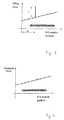
- Figures 1 and 2 show the force transmitted back to the user being generally consistent with the degree of operation of the input device (in that the graph of force against position has a slope).
- the force transmitted back to the user may be generally constant (other than the spike), in which case the graph of force against position will be generally horizontal.
- the force transmitted back to the user may be zero.
- the device 10 includes a driving member 20, that is rotationally connected to the input device, and a follower member 30, which may be connected to a device to be controlled.
- Rotation of the input device causes the driving member to rotate, and (as will be explained later) rotation of the driving member causes the follower member to rotate.
- the driving member and the follower member rotate about the same axis, and may for example be mounted on a single shaft.
- the driving member and the follower member both take the form of sector-shaped plates 22, 32, which can rotate about a common axis.
- the driving member and the follower member are arranged such that the driving member can rotate by a small degree without causing the follower member to rotate (that is, there is a lost-motion mechanism between the driving member and the follower member).
- this is achieved by means of a projection 24 on the driving member 20 which projects towards the follower member 30, and is received in a recess 34 in the follower member 30.
- the recess 34 is elongate in the radial direction, such that when the driving member 20 rotates, the projection 24 moves along the recess 34 in the follower member 30.
- the recess 34 may a slot in the follower member 30, and the projection 24 may pass through the slot.
- the recess is of limited length, and when the device 10 is in its neutral (un-actuated) state, the projection 24 is located at one end of the recess 34.
- Initial rotation of the driving member 20 from the neutral state (shown in Figures 5A to 5D ) will move the projection 24 along the recess 34 until the projection 24 reaches the end of the recess 34 (shown in Figures 6A to 6D ).
- the driving member 20 and the follower member 30 are separated so that rotational motion of the driving member 20 does not automatically cause rotational movement of the follower member 30; if necessary, some form of frictional brake may be provided in association with the follower member 30 to prevent movement in either direction.
- the driving member 20 and the follower member 30 are both in the form of a generally sector-shaped plate 22, 32, and a roller 40 is biased against the edges of the plates 22, 32 by a biasing means 42.
- this biasing means 42 is a mechanical spring, but any suitable device (such as a gas spring) could be used.
- the edges of the plates 22, 32 function as a cam, with the roller 40 functioning as a cam follower.
- the spring 42 is fixed to a housing of the device 10, and so does not move when the driving member 20 and the follower member 30 rotate.
- the profiles of the edges of the plates 22, 32 are generally circular, and so the roller 40 can roll smoothly over the edges of the plates 22, 32 as the plates rotate. (It will be appreciated that the profiles of the edges of the plates 22, 32 move, and the roller 40 is generally stationary; however, as it is easier to visualize the roller 40 moving along the profiles of the edges of the plates 22, 32, this will generally be referred to in the following description.)
- This compression of the spring 42 can take place near the start of the rotation of the input device (and thus near the start of the rotation of the driving member 20), so that a user is informed about the rotation.
- the profiles may have any desired shape, to allow compression of the spring to take place at any appropriate point during operation of the device.
- the "spike” may be felt by the user before the end of the free stroke of the driving member resulting from the lost-motion mechanism. Further, this compression can take place in two or more steps.
- the parts of the profiles which come into contact with the roller 40 during the early parts of the rotation process will be referred to as “earlier parts” or “first parts” of the profiles, and parts of the profiles which come into contact with the roller 40 during later parts of the rotation process will be referred to as “later parts” or “second parts” of the profiles.
- the driving member 20 has a profile which includes a first part 26 of constant radius and a second part 28 of constant radius, wherein the radius of the second part 28 is slightly greater than the radius of the first part 26.
- the first part 26 and the second part 28 are connected by a step 27, which the roller 40 can roll up. As the roller 40 rolls up the step 27, the biasing spring 42 is compressed, to provide the "spike".
- the driving member 20 and follower member 30 are arranged such that when the driving member 20 is rotated by operation of the input device, the step 27 on the driving member 20 reaches the roller 40 at the same time as (or very slightly earlier than) the projection 24 on the driving member 20 reaches the end of the recess 34 in the follower member 30.
- the user feels the "spike” as (or just before) the follower member 30 starts to move. If the user is operating the input device inadvertently, then this "spike” will inform them of the operation, and they can then return the input device to its original (un-actuated) state.
- the "spike” occurs as the follower member starts to rotate.
- the invention is not limited to this, and a spike can occur before or after the follower member starts to rotate.
- the driving member and follower member may be arranged so that the user feels more than one spike during operation.
- the earlier part 36 of the profile of the follower member 30 is a sector of gradually increasing radius, and the later part 38 of the profile of the follower member 30 is a sector of constant radius.
- the two parts 36, 38 of the profile of the follower member are joined smoothly (at point 37).
- the radius at the start of the earlier part 36 of the profile of the follower member 30 is smaller than the radius of the first part 26 of the profile of the driving member 20. Further, the radius of the later part 38 of the profile of the follower member 30 is equal to, or (preferably) very slightly greater than, the radius of the second part 28 of the profile of the driving member 20. Since the earlier part 36 and the later part 38 of the profile of the follower member 30 are joined smoothly, it follows that the radius at the end of the earlier part 36 of the profile of the follower member 30 is the same as the radius of the later part 38 of the profile of the follower member 30, and so is also equal to or very slightly greater than the radius of the second part 28 of the profile of the driving member 20. Thus, the radius of the earlier part 36 of the profile of the follower member 30 increases, from being smaller than the radius of the first part 26 of the profile of the driving member 20 to being equal to very slightly greater than the radius of the second part 28 of the profile of the driving member 20.
- the roller 40 then moves over the smooth joint 37 between the earlier part 36 and the later part 38 of the profile of the follower member 30, and subsequent rotation of the driving member 20 and the follower member 30 continues to move the roller 40 over the later part 38 of the profile of the follower member 30.
- this part of the profile of the follower member 30 has a constant radius, there is no further compression of the biasing spring 42.
- the later part 38 of the profile of the follower member 30 may have a radius which gradually increases.
- the spring 42 will be gradually compressed as the roller 40 moves over the later part 38 of the profile of the follower member 30, and so the force required to gradually compress the spring 42 will be felt by the user as a gradually increasing feedback force.
- the first part 26 of the profile of the driving member 20 need not be circular, and may also have a radius which gradually increases, so that the user will feel a gradually increasing feedback force in the initial part of the rotation of the driving member.
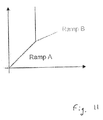
- both the first part 26 of the profile of the driving member 20 and the later part 38 of the profile of the follower member 30 have radii which increase, then the user will feel a gradually increasing feedback force throughout the rotation of the driving member. If the rates of increase of the radii are different, then the user will feel a change in the amount of increase of the feedback force, as schematically shown in Figure 11 .
- the first part 26 of the profile of the driving member 20 corresponds to "Ramp A" and the later part 38 of the profile of the follower member 30 corresponds to "Ramp B". If this change is sufficiently evident, then it may not be necessary to provide a "spike" in the feedback force, and so it may be possible to dispense with the step 27.
- the input device When the device is to be returned to its original state, the input device is rotated in the opposite direction, and this will rotate the driving member 20 back towards its original position. Since the driving member 20 and the follower member 30 are not in contact (other than by means of the projection 24 and the recess 34), and the movement of the follower member is braked by the frictional brake, rotational motion of the driving member 20 does not cause rotational movement of the follower member 30, and so the follower member 30 initially does not move. The roller 40 thus remains in contact with the same point on the profile of the follower member 30.
- the roller Since the radius of the later part 38 of the profile of the follower member 30 is greater than the radius of the second part 28 of the driving member 20, the roller will move along the profile of the follower member 30 as the driving member 20 and the follower member 30 are rotated back to their original positions. Further, the roller 40 will move over the smooth joint 37 between the later part 38 and the earlier part 36 of the profile of the follower member 30 (as can be seen from Figure 9 ), and will then move along the earlier part 36 of the profile of the follower member 30.
- the radius of the earlier part 36 of the profile of the follower member 30 gradually reduces, until it is less than the radius of the first part 26 of the profile of the driving member 20.
- the roller 40 will move along the earlier part 38 of the profile of the follower member 30 until the point where the reducing radius is equal to the radius of the first part 26 of the profile of the driving member 20 (point 50 in Figure 9 ).
- Continued motion of the driving member 20 and follower member 30 will then move the roller 40 along the first part 26 of the profile of the driving member 20, until the roller eventually arrives back at its original position (as shown in Figures 5A to 5D ).
- the biasing spring 42 is gradually uncompressed. At no point in the return motion is the spring 42 compressed further, and so there is no "spike” in force on the return path, as can be seen from Figure 2 .
- the profiles of the driving member and the follower member could be arranged so as to include a step, and thus provide a "spike” in force during the return path if appropriate or desired.
- Means can be provided to bias the driving member 20 into its un-actuated position, so that the device 10 returns to its neutral (un-actuated) state when the user releases the input device.
- These means could take the form of a coil spring or the like, arranged around the shaft on which the driving member 20 and the follower member 30 rotate. These means are preferably relatively weak, so that the bias that they exert can easily be overcome by a user of the device.
- the driving member is rotationally connected to an input device, and the driving member and the follower member rotate about the same axis.
- the driving member and the follower member may move in a straight line.
- the driving member and the follower member may be in the form of generally rectilinear plates (or plates of any suitable shape, depending on the particular application of the device), with an edge of each plate forming the profiles of the driving member and the follower member.
- the device provides feedback to a user to inform them of actuation of the device, and thus helps to avoid inadvertent actuation, with a simple construction.
Landscapes
- Engineering & Computer Science (AREA)
- Physics & Mathematics (AREA)
- General Physics & Mathematics (AREA)
- Automation & Control Theory (AREA)
- General Engineering & Computer Science (AREA)
- Mechanical Engineering (AREA)
- Mechanical Control Devices (AREA)
- Transmission Devices (AREA)
- Electrophotography Configuration And Component (AREA)
- Facsimile Scanning Arrangements (AREA)
- Input From Keyboards Or The Like (AREA)
Abstract
Description
- The present disclosure relates to a force device where the force transmitted back to an operator differs depending on the position of the device and the direction in which the device is operated.
- Situations frequently arise where a device (such as a wheel, a handle or a twist grip) is rotated. For example, a twist grip may be rotated by a user to control machinery.
- In certain circumstances, it is desired to indicate to a user that actuation of the device to be controlled has begun, and this may be done by varying the amount of force transmitted to the user as a result of operation of the device. The force transmitted back to the user will often increase as the amount of rotation of the device increases. However, it may be desirable to provide a "spike" of increased force, as shown in
Figure 1 , so that a user can be made aware that the device is being operated, to avoid inadvertent operation of the device. - The present disclosure seeks to address this issue.
- There is disclosed herein a device for connection to an input device actuated by a user, comprising: a movable driving member for connection to the input device; and a movable follower member; wherein motion of the driving member is only transmitted to the follower member after the driving member has been moved by a certain amount; and wherein means are provided to transmit a force back to the user as the driving member is moved.
- Braking means may be provided to prevent motion of the follower member in either direction until motion of the driving member is transmitted to the follower member.
- Said driving member and said follower member may be arranged to rotate, with rotation of the driving member only being transmitted to the follower member after the driving member has been rotated by a certain amount.
- Said driving member and said follower member may be in the form of plates, which are generally parallel to each other and rotate about an axis generally perpendicular to the plates.
- One of the driving member and the follower member may have a projection, and the other of the driving member and the follower member may have an elongate recess, into which the projection fits; such that rotation of the driving member causes the projection to move along the recess until the projection contacts the end of the recess, and further rotation of the driving member causes the follower member to rotate.
- Said recess may be in the form of a slot in the driving member or the follower member.
- The plates forming the driving member and the follower member may be sector-shaped, and the device may further comprise a roller, which is urged against the edges of the plates by a biasing means such as a spring.
- The biasing means may be fixed to a housing of the device.
- The edge of the plate forming the driving member may have a profile with a step in it, such that when the step is moved past the roller, the biasing spring is compressed, and this compression is felt by the user as an increase in the force transmitted back to the user.
- The step may be located such that the roller contacts the step at or around the point where rotation of the driving member is transmitted to the follower member, such that force is felt by the user as the follower member starts to rotate.
- The following member may have a profile with an earlier part and a later part, the roller contacting the later part of the profile of the follower member after the follower member starts to rotate, and the radius of the later part of the profile of the follower member being equal to or greater than the radius of the part of the profile of the driving member after the step.
- The radius of the earlier part of the profile of the follower member may increase towards the later part of the profile of the follower member, such that the radius at the start of the earlier part of the profile of the follower member is less than the radius at the start of the profile of the driving member, and the radius at the end of the earlier part of the profile of the follower member is equal to or greater than the radius of the step.
- Some exemplary embodiments of the present disclosure will now be described way of example only and with reference to
Figures 1 to 11 , in which: -
Figure 1 shows in a highly schematic form the relationship between the force transmitted back to a user and the degree of operation during actuation of a device by movement of an input device; -
Figure 2 shows in a highly schematic form the relationship between the force transmitted back to a user and the degree of operation during release of the input device; -
Figure 3 is a schematic left side view of the device; -
Figure 4 is a schematic right side view of the device; -
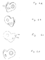
Figures 5A to 5D show the device in its neutral (un-actuated) position; -
Figures 6A to 6D show the device in a state where motion of the driving member is about to be transmitted to the follower member, with an associated spike in the force transmitted back to the user; -
Figures 7A to 7D show the device in a state where the driving member and follower member are moving together; -
Figures 8A to 8D show the device in a state where it is returning to its original neutral position; -
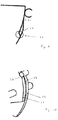
Figure 9 is a close-up side view of early parts of the profiles of the driving member and the follower member, when the device is in its neutral (un-actuated) position; -
Figure 10 is a perspective view of the profiles of the driving member and the follower member; and -
Figure 11 is a view similar toFigure 1 , but shows a different relationship between the force transmitted back to a user and the degree of operation. - The device of the invention can be located between an input device and a device to be controlled, but has more general application. The input device may be actuated (more specifically, rotated) by a user, and may be a wheel, a handle or a twist grip.
- As shown in
Figures 1 and 2 , when the user moves the input device, a force is transmitted back to the user. This force is generally consistent with the degree of operation of the input device; however, as shown inFigure 1 , the user experiences a "spike" in the transmitted force (denoted by the reference "F") shortly after he or she starts to move the input device. This "spike" can inform the user that actuation of the device is about to start, and can help avoid accidental actuation. AsFigure 2 shows, there is no such "spike" when the device is being returned to its original position. -
Figures 1 and 2 show the force transmitted back to the user being generally consistent with the degree of operation of the input device (in that the graph of force against position has a slope). In other forms, the force transmitted back to the user may be generally constant (other than the spike), in which case the graph of force against position will be generally horizontal. The force transmitted back to the user may be zero. - As shown in
Figures 3 and 4 (and alsoFigures 5A ,6A ,7A and8A ), the device 10 includes adriving member 20, that is rotationally connected to the input device, and afollower member 30, which may be connected to a device to be controlled. Rotation of the input device causes the driving member to rotate, and (as will be explained later) rotation of the driving member causes the follower member to rotate. The driving member and the follower member rotate about the same axis, and may for example be mounted on a single shaft. - In the present embodiment, the driving member and the follower member both take the form of sector-
shaped plates - In the present embodiment, this is achieved by means of a projection 24 on the driving
member 20 which projects towards thefollower member 30, and is received in a recess 34 in thefollower member 30. (It will be appreciated that the projection and the recess could equally well be arranged the other way around, with the projection on the follower member and the recess on the driving member.) The recess 34 is elongate in the radial direction, such that when thedriving member 20 rotates, the projection 24 moves along the recess 34 in thefollower member 30. As shown in the drawings, the recess 34 may a slot in thefollower member 30, and the projection 24 may pass through the slot. - The recess is of limited length, and when the device 10 is in its neutral (un-actuated) state, the projection 24 is located at one end of the recess 34. Initial rotation of the
driving member 20 from the neutral state (shown inFigures 5A to 5D ) will move the projection 24 along the recess 34 until the projection 24 reaches the end of the recess 34 (shown inFigures 6A to 6D ). The drivingmember 20 and thefollower member 30 are separated so that rotational motion of the drivingmember 20 does not automatically cause rotational movement of thefollower member 30; if necessary, some form of frictional brake may be provided in association with thefollower member 30 to prevent movement in either direction. - Further rotation of the driving
member 20 will push the projection 24 against the end of the recess 34, and this leads to rotation of thefollower member 30. The braking force applied by the brake is relatively weak, and easily overcome by the further rotation of the driving member. Thus, some rotation of the drivingmember 20 from the neutral state is required before thefollower member 30 rotates, during which time the sector-shaped plate 22 of the drivingmember 20 rotates relative to the sector-shaped plate 32 of thefollower member 30. - Although a particular arrangement of the lost-motion mechanism has been described, the skilled person will appreciate that motion can be transmitted between the driving member and the follower member in any suitable way.
- As mentioned above, the driving
member 20 and thefollower member 30 are both in the form of a generally sector-shaped plate roller 40 is biased against the edges of theplates plates roller 40 functioning as a cam follower. Thespring 42 is fixed to a housing of the device 10, and so does not move when thedriving member 20 and thefollower member 30 rotate. - As shown in
Figure 3 , the profiles of the edges of theplates roller 40 can roll smoothly over the edges of theplates plates roller 40 is generally stationary; however, as it is easier to visualize theroller 40 moving along the profiles of the edges of theplates - However, some regions of the edges of the
plates roller 40 to move so as to compress thespring 42. A certain amount of additional force is required to compress thespring 42, and this additional force can be felt by the user holding the input device as the "spike" previously mentioned. - This compression of the
spring 42 can take place near the start of the rotation of the input device (and thus near the start of the rotation of the driving member 20), so that a user is informed about the rotation. However, it will be appreciated that the profiles may have any desired shape, to allow compression of the spring to take place at any appropriate point during operation of the device. The "spike" may be felt by the user before the end of the free stroke of the driving member resulting from the lost-motion mechanism. Further, this compression can take place in two or more steps. - The embodiment of the device described with reference to
Figures 3 to 10 has profiles in which compression of the spring takes place at a single point during actuation of the device, but the skilled person will appreciate that the invention is not limited to this arrangement. - For simplicity, the parts of the profiles which come into contact with the
roller 40 during the early parts of the rotation process will be referred to as "earlier parts" or "first parts" of the profiles, and parts of the profiles which come into contact with theroller 40 during later parts of the rotation process will be referred to as "later parts" or "second parts" of the profiles. - As best shown in
Figures 5A and 5B , the drivingmember 20 has a profile which includes afirst part 26 of constant radius and asecond part 28 of constant radius, wherein the radius of thesecond part 28 is slightly greater than the radius of thefirst part 26. Thefirst part 26 and thesecond part 28 are connected by astep 27, which theroller 40 can roll up. As theroller 40 rolls up thestep 27, the biasingspring 42 is compressed, to provide the "spike". - In this embodiment, the driving
member 20 andfollower member 30 are arranged such that when the drivingmember 20 is rotated by operation of the input device, thestep 27 on the drivingmember 20 reaches theroller 40 at the same time as (or very slightly earlier than) the projection 24 on the drivingmember 20 reaches the end of the recess 34 in thefollower member 30. Thus, the user feels the "spike" as (or just before) thefollower member 30 starts to move. If the user is operating the input device inadvertently, then this "spike" will inform them of the operation, and they can then return the input device to its original (un-actuated) state. - However, if the user is operating the input device deliberately, then they will continue to rotate the input device after the "spike". As explained above, this will lead to rotation of the
follower member 30. - In this embodiment, the "spike" occurs as the follower member starts to rotate. However, as explained above, the invention is not limited to this, and a spike can occur before or after the follower member starts to rotate. Further, the driving member and follower member may be arranged so that the user feels more than one spike during operation.
- The earlier part 36 of the profile of the
follower member 30 is a sector of gradually increasing radius, and thelater part 38 of the profile of thefollower member 30 is a sector of constant radius. The twoparts 36, 38 of the profile of the follower member are joined smoothly (at point 37). - The radius at the start of the earlier part 36 of the profile of the
follower member 30 is smaller than the radius of thefirst part 26 of the profile of the drivingmember 20. Further, the radius of thelater part 38 of the profile of thefollower member 30 is equal to, or (preferably) very slightly greater than, the radius of thesecond part 28 of the profile of the drivingmember 20. Since the earlier part 36 and thelater part 38 of the profile of thefollower member 30 are joined smoothly, it follows that the radius at the end of the earlier part 36 of the profile of thefollower member 30 is the same as the radius of thelater part 38 of the profile of thefollower member 30, and so is also equal to or very slightly greater than the radius of thesecond part 28 of the profile of the drivingmember 20. Thus, the radius of the earlier part 36 of the profile of thefollower member 30 increases, from being smaller than the radius of thefirst part 26 of the profile of the drivingmember 20 to being equal to very slightly greater than the radius of thesecond part 28 of the profile of the drivingmember 20. - When the
follower member 30 is made to rotate as a result of continued rotation of the driving member 20 (as shown inFigures 6A to 6D , which show the state where the projection 24 on the drivingmember 20 reaches the end of the recess 34 formed in thefollower member 30, andFigures 7A to 7D , which show that both the drivingmember 20 and thefollower member 30 have rotated from the corresponding positions inFigures 6A to 6D ), theroller 40 moves along the start of thesecond part 28 of the profile of the drivingmember 20. Theroller 40 then contacts the end of the earlier part 36 of the profile of thefollower member 30, which as mentioned above has a radius which is equal to or very slightly greater than the radius of thesecond part 28 of the profile of the drivingmember 20. If the radius of the end of the earlier part 36 of the profile of the follower member is very slightly greater than the radius of thesecond part 28 of the profile of the drivingmember 20, this compresses the biasingspring 42 very slightly; however, the compression is sufficiently small that it does not cause the user to feel a spike in the force transmitted back to the user. - The
roller 40 then moves over the smooth joint 37 between the earlier part 36 and thelater part 38 of the profile of thefollower member 30, and subsequent rotation of the drivingmember 20 and thefollower member 30 continues to move theroller 40 over thelater part 38 of the profile of thefollower member 30. As this part of the profile of thefollower member 30 has a constant radius, there is no further compression of the biasingspring 42. - In an alternative form, the
later part 38 of the profile of thefollower member 30 may have a radius which gradually increases. With this arrangement, thespring 42 will be gradually compressed as theroller 40 moves over thelater part 38 of the profile of thefollower member 30, and so the force required to gradually compress thespring 42 will be felt by the user as a gradually increasing feedback force. - Similarly, the
first part 26 of the profile of the drivingmember 20 need not be circular, and may also have a radius which gradually increases, so that the user will feel a gradually increasing feedback force in the initial part of the rotation of the driving member. - If both the
first part 26 of the profile of the drivingmember 20 and thelater part 38 of the profile of thefollower member 30 have radii which increase, then the user will feel a gradually increasing feedback force throughout the rotation of the driving member. If the rates of increase of the radii are different, then the user will feel a change in the amount of increase of the feedback force, as schematically shown inFigure 11 . Thefirst part 26 of the profile of the drivingmember 20 corresponds to "Ramp A" and thelater part 38 of the profile of thefollower member 30 corresponds to "Ramp B". If this change is sufficiently evident, then it may not be necessary to provide a "spike" in the feedback force, and so it may be possible to dispense with thestep 27. - When the device is to be returned to its original state, the input device is rotated in the opposite direction, and this will rotate the driving
member 20 back towards its original position. Since the drivingmember 20 and thefollower member 30 are not in contact (other than by means of the projection 24 and the recess 34), and the movement of the follower member is braked by the frictional brake, rotational motion of the drivingmember 20 does not cause rotational movement of thefollower member 30, and so thefollower member 30 initially does not move. Theroller 40 thus remains in contact with the same point on the profile of thefollower member 30. - However, the projection 24 on the driving
member 20 will be moved back along the recess 34 in thefollower member 30, until it comes into contact with the end of the recess 34 where it was originally located (as shown inFigures 8A to 8D ). At this point, the relative positions of the drivingmember 20 andfollower member 30 will be the same as when motion of the drivingmember 20 originally started (as can be seen by comparingFigures 5A to 5D withFigures 8A to 8D ). However, the rotational positions of the drivingmember 20 and thefollower member 30 relative to theroller 40 are different (as can again be seen by comparingFigures 5A to 5D withFigures 8A to 8D ). - Subsequent rotation of the driving
member 20 towards its original position will overcome the braking force of the frictional brake and will move thefollower member 30, and as a result, theroller 40 will move over the profiles of the drivingmember 20 and thefollower member 30. - Since the radius of the
later part 38 of the profile of thefollower member 30 is greater than the radius of thesecond part 28 of the drivingmember 20, the roller will move along the profile of thefollower member 30 as the drivingmember 20 and thefollower member 30 are rotated back to their original positions. Further, theroller 40 will move over the smooth joint 37 between thelater part 38 and the earlier part 36 of the profile of the follower member 30 (as can be seen fromFigure 9 ), and will then move along the earlier part 36 of the profile of thefollower member 30. - As mentioned above, the radius of the earlier part 36 of the profile of the
follower member 30 gradually reduces, until it is less than the radius of thefirst part 26 of the profile of the drivingmember 20. Thus, theroller 40 will move along theearlier part 38 of the profile of thefollower member 30 until the point where the reducing radius is equal to the radius of thefirst part 26 of the profile of the driving member 20 (point 50 inFigure 9 ). Continued motion of the drivingmember 20 andfollower member 30 will then move theroller 40 along thefirst part 26 of the profile of the drivingmember 20, until the roller eventually arrives back at its original position (as shown inFigures 5A to 5D ). - During the return motion of the
roller 40, the biasingspring 42 is gradually uncompressed. At no point in the return motion is thespring 42 compressed further, and so there is no "spike" in force on the return path, as can be seen fromFigure 2 . However, in alternative embodiments, the profiles of the driving member and the follower member could be arranged so as to include a step, and thus provide a "spike" in force during the return path if appropriate or desired. - Means (not shown) can be provided to bias the driving
member 20 into its un-actuated position, so that the device 10 returns to its neutral (un-actuated) state when the user releases the input device. These means could take the form of a coil spring or the like, arranged around the shaft on which the drivingmember 20 and thefollower member 30 rotate. These means are preferably relatively weak, so that the bias that they exert can easily be overcome by a user of the device. - Further, in the embodiment described above, the driving member is rotationally connected to an input device, and the driving member and the follower member rotate about the same axis. However, it is also possible for the driving member and the follower member to move in a straight line. The driving member and the follower member may be in the form of generally rectilinear plates (or plates of any suitable shape, depending on the particular application of the device), with an edge of each plate forming the profiles of the driving member and the follower member.
- The device provides feedback to a user to inform them of actuation of the device, and thus helps to avoid inadvertent actuation, with a simple construction.
Claims (12)
- A device for connection to an input device actuated by a user, comprising:a movable driving member for connection to the input device; anda movable follower member;wherein motion of the driving member is only transmitted to the follower member after the driving member has been moved by a certain amount;and wherein means are provided to transmit a force back to the user as the driving member is moved.
- A device as claimed in claim 1, wherein braking means are provided to prevent motion of the follower member in either direction until motion of the driving member is transmitted to the follower member.
- A device as claimed in claim 1 or claim 2, wherein said driving member and said follower member are arranged to rotate, and rotation of the driving member is only transmitted to the follower member after the driving member has been rotated by a certain amount.
- A device as claimed in claim 3, wherein said driving member and said follower member are in the form of plates, which are generally parallel to each other and rotate about the same axis generally perpendicular to the plates.
- A device as claimed in claim 3 or claim 4, wherein:one of the driving member and the follower member has a projection;the other of the driving member and the follower member has an elongate recess, into which the projection fits;such that rotation of the driving member causes the projection to move along the recess until the projection contacts the end of the recess, and further rotation of the driving member causes the follower member to rotate.
- A device as claimed in claim 5, wherein said recess is in the form of a slot in the driving member or the follower member.
- A device as claimed in claim 4 or any claim dependent thereon, wherein the plates forming the driving member and the follower member are sector-shaped, and the device further comprises a roller, which is urged against the edges of the plates by a biasing means such as a spring.
- A device as claimed in claim 7, wherein the biasing means is fixed to a housing of the device.
- A device as claimed in claim 7 or claim 8, wherein the edge of the plate forming the driving member has a profile with a step in it, such that when the step is moved past the roller, the biasing means is compressed, and this compression is felt by the user as an increase in the force is transmitted back to the user.
- A device as claimed in claim 9, wherein the step is located such that the roller contacts the step of the driving member at or around the point where rotation of the driving member is transmitted to the follower member, such that force is felt by the user as the follower member starts to rotate.
- A device as claimed in claim 9 or claim 10, wherein the following member has a profile with an earlier part and a later part, and the radius of the later part of the profile of the follower member being equal to or greater than the radius of the part of the profile of the driving member after the step.
- A device as claimed in claim 11, wherein the radius of the earlier part of the profile of the follower member increases towards the later part of the profile of the follower member, such that the radius at the start of the earlier part of the profile of the follower member is less than the radius at the start of the profile of the driving member, and the radius at the end of the earlier part of the profile of the follower member is equal to or greater than the radius of the step.
Priority Applications (5)
| Application Number | Priority Date | Filing Date | Title |
|---|---|---|---|
| EP16305398.6A EP3229098B1 (en) | 2016-04-06 | 2016-04-06 | Device with asymmetric feedback |
| RU2017111256A RU2676200C2 (en) | 2016-04-06 | 2017-04-04 | Device with asymmetric feedback |
| BR102017007021-2A BR102017007021B1 (en) | 2016-04-06 | 2017-04-05 | DEVICE FOR CONNECTION TO A USER-OPERATED INPUT DEVICE |
| CN201710220871.8A CN107291147B (en) | 2016-04-06 | 2017-04-06 | Device with asymmetric feedback |
| US15/480,632 US10372152B2 (en) | 2016-04-06 | 2017-04-06 | Device with asymmetric feedback |
Applications Claiming Priority (1)
| Application Number | Priority Date | Filing Date | Title |
|---|---|---|---|
| EP16305398.6A EP3229098B1 (en) | 2016-04-06 | 2016-04-06 | Device with asymmetric feedback |
Publications (2)
| Publication Number | Publication Date |
|---|---|
| EP3229098A1 true EP3229098A1 (en) | 2017-10-11 |
| EP3229098B1 EP3229098B1 (en) | 2024-07-17 |
Family
ID=55967194
Family Applications (1)
| Application Number | Title | Priority Date | Filing Date |
|---|---|---|---|
| EP16305398.6A Active EP3229098B1 (en) | 2016-04-06 | 2016-04-06 | Device with asymmetric feedback |
Country Status (4)
| Country | Link |
|---|---|
| US (1) | US10372152B2 (en) |
| EP (1) | EP3229098B1 (en) |
| CN (1) | CN107291147B (en) |
| RU (1) | RU2676200C2 (en) |
Families Citing this family (1)
| Publication number | Priority date | Publication date | Assignee | Title |
|---|---|---|---|---|
| AU2021251111B2 (en) * | 2020-04-08 | 2026-03-12 | Boston Scientific Scimed, Inc. | Locking mechanisms for endoscopic devices |
Citations (3)
| Publication number | Priority date | Publication date | Assignee | Title |
|---|---|---|---|---|
| EP1154347A2 (en) * | 2000-04-27 | 2001-11-14 | Caithness Development Ltd. | Pedal mechanism |
| JP2005126022A (en) * | 2003-10-02 | 2005-05-19 | Aisan Ind Co Ltd | Accelerator pedal module |
| DE102010063409A1 (en) * | 2010-12-17 | 2012-06-21 | Ab Elektronik Gmbh | Pedal device for vehicle control device, has link element that is arranged around rotational axis of rotary element and adjusted by motor so that engaged position of rotary element with link element is adjusted |
Family Cites Families (15)
| Publication number | Priority date | Publication date | Assignee | Title |
|---|---|---|---|---|
| US489962A (en) * | 1893-01-17 | Automatic railway pumping mechanism | ||
| GB489962A (en) * | 1937-02-06 | 1938-08-08 | Diamond H Switches Ltd | Improvements in and relating to rotary electric switches |
| US3442146A (en) * | 1967-07-07 | 1969-05-06 | Theodore Simpson | Intermittent rotary motion |
| FR2132998A5 (en) | 1971-04-05 | 1972-11-24 | Citroen Sa | |
| US3902375A (en) * | 1974-03-18 | 1975-09-02 | Admiral Corp | Knob mechanism for TV tuner |
| JPS52158279U (en) | 1976-05-27 | 1977-12-01 | ||
| JPS5943251A (en) * | 1982-09-06 | 1984-03-10 | Yuushin:Kk | Step feeding device |
| US4661085A (en) * | 1985-09-09 | 1987-04-28 | Philips Home Products, Inc. | Lost motion clutch assembly |
| JP2000195370A (en) * | 1998-12-28 | 2000-07-14 | Sony Computer Entertainment Inc | Reaction force generator |
| US20070234842A1 (en) | 2006-04-07 | 2007-10-11 | Ksr International Co. | Electronic throttle control with hysteresis and kickdown |
| CN201129430Y (en) | 2007-12-25 | 2008-10-08 | 梁钟铭 | Gear buffer structure |
| DE102010039415A1 (en) | 2010-08-17 | 2012-02-23 | E.G.O. Elektro-Gerätebau GmbH | Operating device and operating method |
| CN103594258B (en) | 2012-08-15 | 2016-03-09 | 西门子公司 | A kind of switching device |
| DE102014217319A1 (en) * | 2014-08-29 | 2016-03-03 | Robert Bosch Gmbh | Active accelerator pedal with worm gear |
| CN105892687B (en) * | 2016-05-04 | 2018-08-31 | 北京航空航天大学 | A kind of single-degree-of-freedom force feedback handle apparatus and its working method |
-
2016
- 2016-04-06 EP EP16305398.6A patent/EP3229098B1/en active Active
-
2017
- 2017-04-04 RU RU2017111256A patent/RU2676200C2/en active
- 2017-04-06 US US15/480,632 patent/US10372152B2/en active Active
- 2017-04-06 CN CN201710220871.8A patent/CN107291147B/en active Active
Patent Citations (3)
| Publication number | Priority date | Publication date | Assignee | Title |
|---|---|---|---|---|
| EP1154347A2 (en) * | 2000-04-27 | 2001-11-14 | Caithness Development Ltd. | Pedal mechanism |
| JP2005126022A (en) * | 2003-10-02 | 2005-05-19 | Aisan Ind Co Ltd | Accelerator pedal module |
| DE102010063409A1 (en) * | 2010-12-17 | 2012-06-21 | Ab Elektronik Gmbh | Pedal device for vehicle control device, has link element that is arranged around rotational axis of rotary element and adjusted by motor so that engaged position of rotary element with link element is adjusted |
Also Published As
| Publication number | Publication date |
|---|---|
| RU2017111256A (en) | 2018-10-04 |
| US20170293318A1 (en) | 2017-10-12 |
| US10372152B2 (en) | 2019-08-06 |
| RU2676200C2 (en) | 2018-12-26 |
| EP3229098B1 (en) | 2024-07-17 |
| CN107291147A (en) | 2017-10-24 |
| CN107291147B (en) | 2020-08-07 |
| BR102017007021A2 (en) | 2022-11-01 |
| RU2017111256A3 (en) | 2018-10-04 |
Similar Documents
| Publication | Publication Date | Title |
|---|---|---|
| US20130180356A1 (en) | Assistance device for operating a pedal of a motor vehicle and pedal comprising the assistance device | |
| EP3314193B1 (en) | Trigger device | |
| CN104918815B (en) | Pedal system for generating force changes with hysteresis | |
| CN102959265B (en) | Clutch operation device | |
| CN109509648B (en) | Speed reduction mechanism for switching device and switching device | |
| CN108290196B (en) | Cam Grooving Machine | |
| CN108431464B (en) | Shift actuator component for transmission for vehicles | |
| US10372152B2 (en) | Device with asymmetric feedback | |
| KR20110127654A (en) | Control mechanism for friction clutch system with clearance adjustment device | |
| TW201824320A (en) | Locking and unlocking structure of switch device capable of reducing space occupied by structure, simplifying components, and reducing consumption | |
| EP4339145A3 (en) | Yarn winder | |
| CA2507660C (en) | Pedal assembly | |
| JP2014215804A (en) | Reaction force generator | |
| KR101489498B1 (en) | Clutch actuator | |
| KR101565574B1 (en) | Apparatus for adjusting height of seat | |
| TWI690312B (en) | Rotational positioning mechanism and carrier | |
| RU2630593C1 (en) | Switching mechanism in electric drive with manual doubler | |
| JP3751418B2 (en) | Electric power steering device | |
| JP7362328B2 (en) | Accelerator pedal safety device and automobile driving device equipped with the same. | |
| KR101628576B1 (en) | Pedal effort adjusting apparatus | |
| BR102017007021B1 (en) | DEVICE FOR CONNECTION TO A USER-OPERATED INPUT DEVICE | |
| KR20170039396A (en) | Self-energizing clutch of compressor for vehicle | |
| KR101566693B1 (en) | Parking device for automatic transmission | |
| BR102017011404A2 (en) | device for connecting to a user-actuated input device | |
| EP2310713A2 (en) | Brake Assembly for a Utility Vehicle |
Legal Events
| Date | Code | Title | Description |
|---|---|---|---|
| PUAI | Public reference made under article 153(3) epc to a published international application that has entered the european phase |
Free format text: ORIGINAL CODE: 0009012 |
|
| STAA | Information on the status of an ep patent application or granted ep patent |
Free format text: STATUS: THE APPLICATION HAS BEEN PUBLISHED |
|
| AK | Designated contracting states |
Kind code of ref document: A1 Designated state(s): AL AT BE BG CH CY CZ DE DK EE ES FI FR GB GR HR HU IE IS IT LI LT LU LV MC MK MT NL NO PL PT RO RS SE SI SK SM TR |
|
| AX | Request for extension of the european patent |
Extension state: BA ME |
|
| RAP1 | Party data changed (applicant data changed or rights of an application transferred) |
Owner name: RATIER-FIGEAC SAS |
|
| STAA | Information on the status of an ep patent application or granted ep patent |
Free format text: STATUS: REQUEST FOR EXAMINATION WAS MADE |
|
| 17P | Request for examination filed |
Effective date: 20180411 |
|
| RBV | Designated contracting states (corrected) |
Designated state(s): AL AT BE BG CH CY CZ DE DK EE ES FI FR GB GR HR HU IE IS IT LI LT LU LV MC MK MT NL NO PL PT RO RS SE SI SK SM TR |
|
| RIC1 | Information provided on ipc code assigned before grant |
Ipc: G05G 5/03 20080401AFI20161114BHEP |
|
| STAA | Information on the status of an ep patent application or granted ep patent |
Free format text: STATUS: EXAMINATION IS IN PROGRESS |
|
| 17Q | First examination report despatched |
Effective date: 20210701 |
|
| GRAP | Despatch of communication of intention to grant a patent |
Free format text: ORIGINAL CODE: EPIDOSNIGR1 |
|
| STAA | Information on the status of an ep patent application or granted ep patent |
Free format text: STATUS: GRANT OF PATENT IS INTENDED |
|
| INTG | Intention to grant announced |
Effective date: 20240207 |
|
| GRAS | Grant fee paid |
Free format text: ORIGINAL CODE: EPIDOSNIGR3 |
|
| GRAA | (expected) grant |
Free format text: ORIGINAL CODE: 0009210 |
|
| STAA | Information on the status of an ep patent application or granted ep patent |
Free format text: STATUS: THE PATENT HAS BEEN GRANTED |
|
| AK | Designated contracting states |
Kind code of ref document: B1 Designated state(s): AL AT BE BG CH CY CZ DE DK EE ES FI FR GB GR HR HU IE IS IT LI LT LU LV MC MK MT NL NO PL PT RO RS SE SI SK SM TR |
|
| REG | Reference to a national code |
Ref country code: GB Ref legal event code: FG4D |
|
| REG | Reference to a national code |
Ref country code: CH Ref legal event code: EP |
|
| REG | Reference to a national code |
Ref country code: DE Ref legal event code: R096 Ref document number: 602016088422 Country of ref document: DE |
|
| REG | Reference to a national code |
Ref country code: IE Ref legal event code: FG4D |
|
| REG | Reference to a national code |
Ref country code: LT Ref legal event code: MG9D |
|
| REG | Reference to a national code |
Ref country code: NL Ref legal event code: MP Effective date: 20240717 |
|
| PG25 | Lapsed in a contracting state [announced via postgrant information from national office to epo] |
Ref country code: PT Free format text: LAPSE BECAUSE OF FAILURE TO SUBMIT A TRANSLATION OF THE DESCRIPTION OR TO PAY THE FEE WITHIN THE PRESCRIBED TIME-LIMIT Effective date: 20241118 |
|
| REG | Reference to a national code |
Ref country code: AT Ref legal event code: MK05 Ref document number: 1704745 Country of ref document: AT Kind code of ref document: T Effective date: 20240717 |
|
| PG25 | Lapsed in a contracting state [announced via postgrant information from national office to epo] |
Ref country code: NL Free format text: LAPSE BECAUSE OF FAILURE TO SUBMIT A TRANSLATION OF THE DESCRIPTION OR TO PAY THE FEE WITHIN THE PRESCRIBED TIME-LIMIT Effective date: 20240717 |
|
| PG25 | Lapsed in a contracting state [announced via postgrant information from national office to epo] |
Ref country code: PT Free format text: LAPSE BECAUSE OF FAILURE TO SUBMIT A TRANSLATION OF THE DESCRIPTION OR TO PAY THE FEE WITHIN THE PRESCRIBED TIME-LIMIT Effective date: 20241118 Ref country code: NL Free format text: LAPSE BECAUSE OF FAILURE TO SUBMIT A TRANSLATION OF THE DESCRIPTION OR TO PAY THE FEE WITHIN THE PRESCRIBED TIME-LIMIT Effective date: 20240717 |
|
| PG25 | Lapsed in a contracting state [announced via postgrant information from national office to epo] |
Ref country code: NO Free format text: LAPSE BECAUSE OF FAILURE TO SUBMIT A TRANSLATION OF THE DESCRIPTION OR TO PAY THE FEE WITHIN THE PRESCRIBED TIME-LIMIT Effective date: 20241017 |
|
| PG25 | Lapsed in a contracting state [announced via postgrant information from national office to epo] |
Ref country code: FI Free format text: LAPSE BECAUSE OF FAILURE TO SUBMIT A TRANSLATION OF THE DESCRIPTION OR TO PAY THE FEE WITHIN THE PRESCRIBED TIME-LIMIT Effective date: 20240717 Ref country code: PL Free format text: LAPSE BECAUSE OF FAILURE TO SUBMIT A TRANSLATION OF THE DESCRIPTION OR TO PAY THE FEE WITHIN THE PRESCRIBED TIME-LIMIT Effective date: 20240717 Ref country code: GR Free format text: LAPSE BECAUSE OF FAILURE TO SUBMIT A TRANSLATION OF THE DESCRIPTION OR TO PAY THE FEE WITHIN THE PRESCRIBED TIME-LIMIT Effective date: 20241018 |
|
| PG25 | Lapsed in a contracting state [announced via postgrant information from national office to epo] |
Ref country code: BG Free format text: LAPSE BECAUSE OF FAILURE TO SUBMIT A TRANSLATION OF THE DESCRIPTION OR TO PAY THE FEE WITHIN THE PRESCRIBED TIME-LIMIT Effective date: 20240717 |
|
| PG25 | Lapsed in a contracting state [announced via postgrant information from national office to epo] |
Ref country code: LV Free format text: LAPSE BECAUSE OF FAILURE TO SUBMIT A TRANSLATION OF THE DESCRIPTION OR TO PAY THE FEE WITHIN THE PRESCRIBED TIME-LIMIT Effective date: 20240717 |
|
| PG25 | Lapsed in a contracting state [announced via postgrant information from national office to epo] |
Ref country code: IS Free format text: LAPSE BECAUSE OF FAILURE TO SUBMIT A TRANSLATION OF THE DESCRIPTION OR TO PAY THE FEE WITHIN THE PRESCRIBED TIME-LIMIT Effective date: 20241117 Ref country code: AT Free format text: LAPSE BECAUSE OF FAILURE TO SUBMIT A TRANSLATION OF THE DESCRIPTION OR TO PAY THE FEE WITHIN THE PRESCRIBED TIME-LIMIT Effective date: 20240717 |
|
| PG25 | Lapsed in a contracting state [announced via postgrant information from national office to epo] |
Ref country code: HR Free format text: LAPSE BECAUSE OF FAILURE TO SUBMIT A TRANSLATION OF THE DESCRIPTION OR TO PAY THE FEE WITHIN THE PRESCRIBED TIME-LIMIT Effective date: 20240717 |
|
| PG25 | Lapsed in a contracting state [announced via postgrant information from national office to epo] |
Ref country code: ES Free format text: LAPSE BECAUSE OF FAILURE TO SUBMIT A TRANSLATION OF THE DESCRIPTION OR TO PAY THE FEE WITHIN THE PRESCRIBED TIME-LIMIT Effective date: 20240717 Ref country code: RS Free format text: LAPSE BECAUSE OF FAILURE TO SUBMIT A TRANSLATION OF THE DESCRIPTION OR TO PAY THE FEE WITHIN THE PRESCRIBED TIME-LIMIT Effective date: 20241017 |
|
| PG25 | Lapsed in a contracting state [announced via postgrant information from national office to epo] |
Ref country code: RS Free format text: LAPSE BECAUSE OF FAILURE TO SUBMIT A TRANSLATION OF THE DESCRIPTION OR TO PAY THE FEE WITHIN THE PRESCRIBED TIME-LIMIT Effective date: 20241017 Ref country code: PL Free format text: LAPSE BECAUSE OF FAILURE TO SUBMIT A TRANSLATION OF THE DESCRIPTION OR TO PAY THE FEE WITHIN THE PRESCRIBED TIME-LIMIT Effective date: 20240717 Ref country code: NO Free format text: LAPSE BECAUSE OF FAILURE TO SUBMIT A TRANSLATION OF THE DESCRIPTION OR TO PAY THE FEE WITHIN THE PRESCRIBED TIME-LIMIT Effective date: 20241017 Ref country code: LV Free format text: LAPSE BECAUSE OF FAILURE TO SUBMIT A TRANSLATION OF THE DESCRIPTION OR TO PAY THE FEE WITHIN THE PRESCRIBED TIME-LIMIT Effective date: 20240717 Ref country code: IS Free format text: LAPSE BECAUSE OF FAILURE TO SUBMIT A TRANSLATION OF THE DESCRIPTION OR TO PAY THE FEE WITHIN THE PRESCRIBED TIME-LIMIT Effective date: 20241117 Ref country code: HR Free format text: LAPSE BECAUSE OF FAILURE TO SUBMIT A TRANSLATION OF THE DESCRIPTION OR TO PAY THE FEE WITHIN THE PRESCRIBED TIME-LIMIT Effective date: 20240717 Ref country code: GR Free format text: LAPSE BECAUSE OF FAILURE TO SUBMIT A TRANSLATION OF THE DESCRIPTION OR TO PAY THE FEE WITHIN THE PRESCRIBED TIME-LIMIT Effective date: 20241018 Ref country code: FI Free format text: LAPSE BECAUSE OF FAILURE TO SUBMIT A TRANSLATION OF THE DESCRIPTION OR TO PAY THE FEE WITHIN THE PRESCRIBED TIME-LIMIT Effective date: 20240717 Ref country code: ES Free format text: LAPSE BECAUSE OF FAILURE TO SUBMIT A TRANSLATION OF THE DESCRIPTION OR TO PAY THE FEE WITHIN THE PRESCRIBED TIME-LIMIT Effective date: 20240717 Ref country code: BG Free format text: LAPSE BECAUSE OF FAILURE TO SUBMIT A TRANSLATION OF THE DESCRIPTION OR TO PAY THE FEE WITHIN THE PRESCRIBED TIME-LIMIT Effective date: 20240717 Ref country code: AT Free format text: LAPSE BECAUSE OF FAILURE TO SUBMIT A TRANSLATION OF THE DESCRIPTION OR TO PAY THE FEE WITHIN THE PRESCRIBED TIME-LIMIT Effective date: 20240717 |
|
| PG25 | Lapsed in a contracting state [announced via postgrant information from national office to epo] |
Ref country code: RO Free format text: LAPSE BECAUSE OF FAILURE TO SUBMIT A TRANSLATION OF THE DESCRIPTION OR TO PAY THE FEE WITHIN THE PRESCRIBED TIME-LIMIT Effective date: 20240717 Ref country code: DK Free format text: LAPSE BECAUSE OF FAILURE TO SUBMIT A TRANSLATION OF THE DESCRIPTION OR TO PAY THE FEE WITHIN THE PRESCRIBED TIME-LIMIT Effective date: 20240717 Ref country code: SM Free format text: LAPSE BECAUSE OF FAILURE TO SUBMIT A TRANSLATION OF THE DESCRIPTION OR TO PAY THE FEE WITHIN THE PRESCRIBED TIME-LIMIT Effective date: 20240717 |
|
| REG | Reference to a national code |
Ref country code: DE Ref legal event code: R097 Ref document number: 602016088422 Country of ref document: DE |
|
| PG25 | Lapsed in a contracting state [announced via postgrant information from national office to epo] |
Ref country code: EE Free format text: LAPSE BECAUSE OF FAILURE TO SUBMIT A TRANSLATION OF THE DESCRIPTION OR TO PAY THE FEE WITHIN THE PRESCRIBED TIME-LIMIT Effective date: 20240717 |
|
| PG25 | Lapsed in a contracting state [announced via postgrant information from national office to epo] |
Ref country code: CZ Free format text: LAPSE BECAUSE OF FAILURE TO SUBMIT A TRANSLATION OF THE DESCRIPTION OR TO PAY THE FEE WITHIN THE PRESCRIBED TIME-LIMIT Effective date: 20240717 |
|
| PG25 | Lapsed in a contracting state [announced via postgrant information from national office to epo] |
Ref country code: SK Free format text: LAPSE BECAUSE OF FAILURE TO SUBMIT A TRANSLATION OF THE DESCRIPTION OR TO PAY THE FEE WITHIN THE PRESCRIBED TIME-LIMIT Effective date: 20240717 |
|
| PLBE | No opposition filed within time limit |
Free format text: ORIGINAL CODE: 0009261 |
|
| STAA | Information on the status of an ep patent application or granted ep patent |
Free format text: STATUS: NO OPPOSITION FILED WITHIN TIME LIMIT |
|
| 26N | No opposition filed |
Effective date: 20250422 |
|
| PG25 | Lapsed in a contracting state [announced via postgrant information from national office to epo] |
Ref country code: SE Free format text: LAPSE BECAUSE OF FAILURE TO SUBMIT A TRANSLATION OF THE DESCRIPTION OR TO PAY THE FEE WITHIN THE PRESCRIBED TIME-LIMIT Effective date: 20240717 |
|
| REG | Reference to a national code |
Ref country code: DE Ref legal event code: R119 Ref document number: 602016088422 Country of ref document: DE |
|
| REG | Reference to a national code |
Ref country code: CH Ref legal event code: H13 Free format text: ST27 STATUS EVENT CODE: U-0-0-H10-H13 (AS PROVIDED BY THE NATIONAL OFFICE) Effective date: 20251125 |
|
| PG25 | Lapsed in a contracting state [announced via postgrant information from national office to epo] |
Ref country code: LU Free format text: LAPSE BECAUSE OF NON-PAYMENT OF DUE FEES Effective date: 20250406 |
|
| PG25 | Lapsed in a contracting state [announced via postgrant information from national office to epo] |
Ref country code: MC Free format text: LAPSE BECAUSE OF FAILURE TO SUBMIT A TRANSLATION OF THE DESCRIPTION OR TO PAY THE FEE WITHIN THE PRESCRIBED TIME-LIMIT Effective date: 20240717 |
|
| REG | Reference to a national code |
Ref country code: BE Ref legal event code: MM Effective date: 20250430 |
|
| PG25 | Lapsed in a contracting state [announced via postgrant information from national office to epo] |
Ref country code: DE Free format text: LAPSE BECAUSE OF NON-PAYMENT OF DUE FEES Effective date: 20251104 |
|
| PG25 | Lapsed in a contracting state [announced via postgrant information from national office to epo] |
Ref country code: BE Free format text: LAPSE BECAUSE OF NON-PAYMENT OF DUE FEES Effective date: 20250430 |
|
| PG25 | Lapsed in a contracting state [announced via postgrant information from national office to epo] |
Ref country code: CH Free format text: LAPSE BECAUSE OF NON-PAYMENT OF DUE FEES Effective date: 20250430 |
|
| PG25 | Lapsed in a contracting state [announced via postgrant information from national office to epo] |
Ref country code: IT Free format text: LAPSE BECAUSE OF FAILURE TO SUBMIT A TRANSLATION OF THE DESCRIPTION OR TO PAY THE FEE WITHIN THE PRESCRIBED TIME-LIMIT Effective date: 20240717 |
|
| PGFP | Annual fee paid to national office [announced via postgrant information from national office to epo] |
Ref country code: GB Payment date: 20260319 Year of fee payment: 11 |
|
| PG25 | Lapsed in a contracting state [announced via postgrant information from national office to epo] |
Ref country code: IE Free format text: LAPSE BECAUSE OF NON-PAYMENT OF DUE FEES Effective date: 20250406 |
|
| PGFP | Annual fee paid to national office [announced via postgrant information from national office to epo] |
Ref country code: FR Payment date: 20260319 Year of fee payment: 11 |
|
| PG25 | Lapsed in a contracting state [announced via postgrant information from national office to epo] |
Ref country code: CY Free format text: LAPSE BECAUSE OF FAILURE TO SUBMIT A TRANSLATION OF THE DESCRIPTION OR TO PAY THE FEE WITHIN THE PRESCRIBED TIME-LIMIT Effective date: 20240717 |
|
| PG25 | Lapsed in a contracting state [announced via postgrant information from national office to epo] |
Ref country code: LT Free format text: LAPSE BECAUSE OF FAILURE TO SUBMIT A TRANSLATION OF THE DESCRIPTION OR TO PAY THE FEE WITHIN THE PRESCRIBED TIME-LIMIT Effective date: 20240717 |