EP3228958A2 - Linkage control method and apparatus for indoor and outdoor units of precision air conditioner - Google Patents
Linkage control method and apparatus for indoor and outdoor units of precision air conditioner Download PDFInfo
- Publication number
- EP3228958A2 EP3228958A2 EP17160108.1A EP17160108A EP3228958A2 EP 3228958 A2 EP3228958 A2 EP 3228958A2 EP 17160108 A EP17160108 A EP 17160108A EP 3228958 A2 EP3228958 A2 EP 3228958A2
- Authority
- EP
- European Patent Office
- Prior art keywords
- target
- temperature
- evaporator
- condenser
- compressor
- Prior art date
- Legal status (The legal status is an assumption and is not a legal conclusion. Google has not performed a legal analysis and makes no representation as to the accuracy of the status listed.)
- Granted
Links
- 238000000034 method Methods 0.000 title claims abstract description 26
- 238000001704 evaporation Methods 0.000 claims abstract description 117
- 238000001816 cooling Methods 0.000 claims abstract description 40
- 230000006870 function Effects 0.000 claims description 118
- 239000003507 refrigerant Substances 0.000 claims description 46
- 238000005457 optimization Methods 0.000 description 22
- 238000010586 diagram Methods 0.000 description 10
- 230000000694 effects Effects 0.000 description 7
- 230000003247 decreasing effect Effects 0.000 description 6
- 230000009286 beneficial effect Effects 0.000 description 5
- 230000008859 change Effects 0.000 description 5
- 239000007788 liquid Substances 0.000 description 5
- 230000008569 process Effects 0.000 description 4
- 238000004378 air conditioning Methods 0.000 description 2
- 238000006073 displacement reaction Methods 0.000 description 2
- 238000005265 energy consumption Methods 0.000 description 2
- 230000007246 mechanism Effects 0.000 description 2
- 238000004458 analytical method Methods 0.000 description 1
- 238000004364 calculation method Methods 0.000 description 1
- 238000005516 engineering process Methods 0.000 description 1
- 230000017525 heat dissipation Effects 0.000 description 1
- 238000012986 modification Methods 0.000 description 1
- 230000004048 modification Effects 0.000 description 1
- 238000011144 upstream manufacturing Methods 0.000 description 1
Images


Classifications
-
- F—MECHANICAL ENGINEERING; LIGHTING; HEATING; WEAPONS; BLASTING
- F24—HEATING; RANGES; VENTILATING
- F24F—AIR-CONDITIONING; AIR-HUMIDIFICATION; VENTILATION; USE OF AIR CURRENTS FOR SCREENING
- F24F2110/00—Control inputs relating to air properties
- F24F2110/10—Temperature
-
- F—MECHANICAL ENGINEERING; LIGHTING; HEATING; WEAPONS; BLASTING
- F25—REFRIGERATION OR COOLING; COMBINED HEATING AND REFRIGERATION SYSTEMS; HEAT PUMP SYSTEMS; MANUFACTURE OR STORAGE OF ICE; LIQUEFACTION SOLIDIFICATION OF GASES
- F25B—REFRIGERATION MACHINES, PLANTS OR SYSTEMS; COMBINED HEATING AND REFRIGERATION SYSTEMS; HEAT PUMP SYSTEMS
- F25B49/00—Arrangement or mounting of control or safety devices
- F25B49/02—Arrangement or mounting of control or safety devices for compression type machines, plants or systems
-
- F—MECHANICAL ENGINEERING; LIGHTING; HEATING; WEAPONS; BLASTING
- F24—HEATING; RANGES; VENTILATING
- F24F—AIR-CONDITIONING; AIR-HUMIDIFICATION; VENTILATION; USE OF AIR CURRENTS FOR SCREENING
- F24F11/00—Control or safety arrangements
- F24F11/30—Control or safety arrangements for purposes related to the operation of the system, e.g. for safety or monitoring
-
- F—MECHANICAL ENGINEERING; LIGHTING; HEATING; WEAPONS; BLASTING
- F24—HEATING; RANGES; VENTILATING
- F24F—AIR-CONDITIONING; AIR-HUMIDIFICATION; VENTILATION; USE OF AIR CURRENTS FOR SCREENING
- F24F11/00—Control or safety arrangements
- F24F11/62—Control or safety arrangements characterised by the type of control or by internal processing, e.g. using fuzzy logic, adaptive control or estimation of values
-
- F—MECHANICAL ENGINEERING; LIGHTING; HEATING; WEAPONS; BLASTING
- F24—HEATING; RANGES; VENTILATING
- F24F—AIR-CONDITIONING; AIR-HUMIDIFICATION; VENTILATION; USE OF AIR CURRENTS FOR SCREENING
- F24F11/00—Control or safety arrangements
- F24F11/70—Control systems characterised by their outputs; Constructional details thereof
- F24F11/72—Control systems characterised by their outputs; Constructional details thereof for controlling the supply of treated air, e.g. its pressure
- F24F11/79—Control systems characterised by their outputs; Constructional details thereof for controlling the supply of treated air, e.g. its pressure for controlling the direction of the supplied air
-
- F—MECHANICAL ENGINEERING; LIGHTING; HEATING; WEAPONS; BLASTING
- F24—HEATING; RANGES; VENTILATING
- F24F—AIR-CONDITIONING; AIR-HUMIDIFICATION; VENTILATION; USE OF AIR CURRENTS FOR SCREENING
- F24F2110/00—Control inputs relating to air properties
- F24F2110/20—Humidity
-
- F—MECHANICAL ENGINEERING; LIGHTING; HEATING; WEAPONS; BLASTING
- F25—REFRIGERATION OR COOLING; COMBINED HEATING AND REFRIGERATION SYSTEMS; HEAT PUMP SYSTEMS; MANUFACTURE OR STORAGE OF ICE; LIQUEFACTION SOLIDIFICATION OF GASES
- F25B—REFRIGERATION MACHINES, PLANTS OR SYSTEMS; COMBINED HEATING AND REFRIGERATION SYSTEMS; HEAT PUMP SYSTEMS
- F25B49/00—Arrangement or mounting of control or safety devices
- F25B49/02—Arrangement or mounting of control or safety devices for compression type machines, plants or systems
- F25B49/022—Compressor control arrangements
-
- F—MECHANICAL ENGINEERING; LIGHTING; HEATING; WEAPONS; BLASTING
- F25—REFRIGERATION OR COOLING; COMBINED HEATING AND REFRIGERATION SYSTEMS; HEAT PUMP SYSTEMS; MANUFACTURE OR STORAGE OF ICE; LIQUEFACTION SOLIDIFICATION OF GASES
- F25B—REFRIGERATION MACHINES, PLANTS OR SYSTEMS; COMBINED HEATING AND REFRIGERATION SYSTEMS; HEAT PUMP SYSTEMS
- F25B49/00—Arrangement or mounting of control or safety devices
- F25B49/02—Arrangement or mounting of control or safety devices for compression type machines, plants or systems
- F25B49/027—Condenser control arrangements
-
- F—MECHANICAL ENGINEERING; LIGHTING; HEATING; WEAPONS; BLASTING
- F24—HEATING; RANGES; VENTILATING
- F24F—AIR-CONDITIONING; AIR-HUMIDIFICATION; VENTILATION; USE OF AIR CURRENTS FOR SCREENING
- F24F11/00—Control or safety arrangements
- F24F11/62—Control or safety arrangements characterised by the type of control or by internal processing, e.g. using fuzzy logic, adaptive control or estimation of values
- F24F11/63—Electronic processing
-
- F—MECHANICAL ENGINEERING; LIGHTING; HEATING; WEAPONS; BLASTING
- F25—REFRIGERATION OR COOLING; COMBINED HEATING AND REFRIGERATION SYSTEMS; HEAT PUMP SYSTEMS; MANUFACTURE OR STORAGE OF ICE; LIQUEFACTION SOLIDIFICATION OF GASES
- F25B—REFRIGERATION MACHINES, PLANTS OR SYSTEMS; COMBINED HEATING AND REFRIGERATION SYSTEMS; HEAT PUMP SYSTEMS
- F25B2500/00—Problems to be solved
- F25B2500/19—Calculation of parameters
-
- F—MECHANICAL ENGINEERING; LIGHTING; HEATING; WEAPONS; BLASTING
- F25—REFRIGERATION OR COOLING; COMBINED HEATING AND REFRIGERATION SYSTEMS; HEAT PUMP SYSTEMS; MANUFACTURE OR STORAGE OF ICE; LIQUEFACTION SOLIDIFICATION OF GASES
- F25B—REFRIGERATION MACHINES, PLANTS OR SYSTEMS; COMBINED HEATING AND REFRIGERATION SYSTEMS; HEAT PUMP SYSTEMS
- F25B2600/00—Control issues
- F25B2600/02—Compressor control
- F25B2600/025—Compressor control by controlling speed
- F25B2600/0253—Compressor control by controlling speed with variable speed
-
- F—MECHANICAL ENGINEERING; LIGHTING; HEATING; WEAPONS; BLASTING
- F25—REFRIGERATION OR COOLING; COMBINED HEATING AND REFRIGERATION SYSTEMS; HEAT PUMP SYSTEMS; MANUFACTURE OR STORAGE OF ICE; LIQUEFACTION SOLIDIFICATION OF GASES
- F25B—REFRIGERATION MACHINES, PLANTS OR SYSTEMS; COMBINED HEATING AND REFRIGERATION SYSTEMS; HEAT PUMP SYSTEMS
- F25B2600/00—Control issues
- F25B2600/11—Fan speed control
- F25B2600/111—Fan speed control of condenser fans
-
- F—MECHANICAL ENGINEERING; LIGHTING; HEATING; WEAPONS; BLASTING
- F25—REFRIGERATION OR COOLING; COMBINED HEATING AND REFRIGERATION SYSTEMS; HEAT PUMP SYSTEMS; MANUFACTURE OR STORAGE OF ICE; LIQUEFACTION SOLIDIFICATION OF GASES
- F25B—REFRIGERATION MACHINES, PLANTS OR SYSTEMS; COMBINED HEATING AND REFRIGERATION SYSTEMS; HEAT PUMP SYSTEMS
- F25B2600/00—Control issues
- F25B2600/11—Fan speed control
- F25B2600/112—Fan speed control of evaporator fans
-
- F—MECHANICAL ENGINEERING; LIGHTING; HEATING; WEAPONS; BLASTING
- F25—REFRIGERATION OR COOLING; COMBINED HEATING AND REFRIGERATION SYSTEMS; HEAT PUMP SYSTEMS; MANUFACTURE OR STORAGE OF ICE; LIQUEFACTION SOLIDIFICATION OF GASES
- F25B—REFRIGERATION MACHINES, PLANTS OR SYSTEMS; COMBINED HEATING AND REFRIGERATION SYSTEMS; HEAT PUMP SYSTEMS
- F25B2600/00—Control issues
- F25B2600/17—Control issues by controlling the pressure of the condenser
-
- F—MECHANICAL ENGINEERING; LIGHTING; HEATING; WEAPONS; BLASTING
- F25—REFRIGERATION OR COOLING; COMBINED HEATING AND REFRIGERATION SYSTEMS; HEAT PUMP SYSTEMS; MANUFACTURE OR STORAGE OF ICE; LIQUEFACTION SOLIDIFICATION OF GASES
- F25B—REFRIGERATION MACHINES, PLANTS OR SYSTEMS; COMBINED HEATING AND REFRIGERATION SYSTEMS; HEAT PUMP SYSTEMS
- F25B2700/00—Sensing or detecting of parameters; Sensors therefor
- F25B2700/19—Pressures
- F25B2700/195—Pressures of the condenser
-
- F—MECHANICAL ENGINEERING; LIGHTING; HEATING; WEAPONS; BLASTING
- F25—REFRIGERATION OR COOLING; COMBINED HEATING AND REFRIGERATION SYSTEMS; HEAT PUMP SYSTEMS; MANUFACTURE OR STORAGE OF ICE; LIQUEFACTION SOLIDIFICATION OF GASES
- F25B—REFRIGERATION MACHINES, PLANTS OR SYSTEMS; COMBINED HEATING AND REFRIGERATION SYSTEMS; HEAT PUMP SYSTEMS
- F25B2700/00—Sensing or detecting of parameters; Sensors therefor
- F25B2700/21—Temperatures
- F25B2700/2117—Temperatures of an evaporator
- F25B2700/21171—Temperatures of an evaporator of the fluid cooled by the evaporator
- F25B2700/21172—Temperatures of an evaporator of the fluid cooled by the evaporator at the inlet
-
- F—MECHANICAL ENGINEERING; LIGHTING; HEATING; WEAPONS; BLASTING
- F25—REFRIGERATION OR COOLING; COMBINED HEATING AND REFRIGERATION SYSTEMS; HEAT PUMP SYSTEMS; MANUFACTURE OR STORAGE OF ICE; LIQUEFACTION SOLIDIFICATION OF GASES
- F25B—REFRIGERATION MACHINES, PLANTS OR SYSTEMS; COMBINED HEATING AND REFRIGERATION SYSTEMS; HEAT PUMP SYSTEMS
- F25B2700/00—Sensing or detecting of parameters; Sensors therefor
- F25B2700/21—Temperatures
- F25B2700/2117—Temperatures of an evaporator
- F25B2700/21171—Temperatures of an evaporator of the fluid cooled by the evaporator
- F25B2700/21173—Temperatures of an evaporator of the fluid cooled by the evaporator at the outlet
-
- Y—GENERAL TAGGING OF NEW TECHNOLOGICAL DEVELOPMENTS; GENERAL TAGGING OF CROSS-SECTIONAL TECHNOLOGIES SPANNING OVER SEVERAL SECTIONS OF THE IPC; TECHNICAL SUBJECTS COVERED BY FORMER USPC CROSS-REFERENCE ART COLLECTIONS [XRACs] AND DIGESTS
- Y02—TECHNOLOGIES OR APPLICATIONS FOR MITIGATION OR ADAPTATION AGAINST CLIMATE CHANGE
- Y02B—CLIMATE CHANGE MITIGATION TECHNOLOGIES RELATED TO BUILDINGS, e.g. HOUSING, HOUSE APPLIANCES OR RELATED END-USER APPLICATIONS
- Y02B30/00—Energy efficient heating, ventilation or air conditioning [HVAC]
- Y02B30/70—Efficient control or regulation technologies, e.g. for control of refrigerant flow, motor or heating
Abstract
Description
- The present invention relates to the field of electronic communications technologies, and in particular, to a linkage control method and apparatus for indoor and outdoor units of a precision air conditioner.
- For IT devices in a data center, high power density, heavy heat load, and a relatively strict requirement on temperature and humidity need a precision air conditioner system specific to an equipment room, to ensure stable running of the data center. According to an energy consumption analysis of the data center, the precision air conditioner system is a system with highest energy consumption in the data center except the IT devices, and power consumption of the precision air conditioner system occupies 35% to 40% of total power consumption of the data center. Improving a COP of the precision air conditioner system is the key to energy saving of the data center, and the COP is a ratio of a heat capacity (C) to an input power (P), that is, a coefficient of performance of an air conditioner.
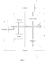
- The precision air conditioner system includes major components such as a compressor, a condenser (an outdoor unit), an expansion valve, and an evaporator (an indoor unit). As shown in
FIG. 2 , the compressor compresses a gaseous refrigerant into a high-temperature and high-pressure state, and sends the compressed refrigerant to the condenser. After heat dissipation, the refrigerant changes into a middle-temperature and high-pressure liquid state. The liquid refrigerant flows through a throttle mechanism (the expansion valve) and changes into a low-pressure and low-temperature gas-liquid mixed state, and then enters the evaporator (the indoor unit). The gas-liquid two-phase refrigerant is evaporated in the evaporator, and during a phase change from liquid to gas, the refrigerant absorbs a large amount of heat, and cools an indoor environment. The refrigerant from the evaporator is in a superheated gaseous state, and then the gaseous refrigerant flows back to the compressor to continue the circulation. - The condenser and the evaporator have matching fans, and a function of the fans is to enhance a heat exchange effect by means of forced convection. Rotational speeds of the fans affect a capacity of heat exchange between the condenser and the evaporator. When the data center is running, cooling load changes with fluctuation of heat generated by the IT devices, and the compressor, the fan of the evaporator, and the fan of the condenser in a cooling system need to be adjusted in terms of rotational speed, so that cooling capacity output matches a cooling capacity requirement.
- To adjust and control the rotational speeds of the fans, in the precision air conditioner system, a pressure sensor is installed at an inlet end of the condenser, so as to detect pressure of the high-pressure gaseous refrigerant transmitted from the compressor (therefore, the pressure sensor is also referred to as a high-pressure sensor). A larger pressure value detected by the sensor indicates a higher saturation temperature of the refrigerant under the pressure, and further a higher heat exchange capacity that needs to be implemented by a heat exchanger, so that the rotational speed of the fan of the condenser needs to be increased; otherwise, the rotational speed of the fan needs to be decreased. For the evaporator, temperature sensors are installed at an inlet and an outlet that are along an air flow direction, so as to detect a temperature difference between air entering and air leaving the evaporator. For the evaporator, a product of an air specific heat capacity, an air temperature difference between the inlet and the outlet, and an air volume approximates to a constant. A smaller air temperature difference between the inlet and the outlet indicates a relatively greater air volume, so that the rotational speed of the fan of the evaporator needs to be decreased; otherwise, the rotational speed of the fan of the evaporator needs to be increased.
- By convention, a target control value of the rotational speed of the compressor is set according to temperature difference load. After the rotational speed of the compressor is adjusted to a target rotational speed, the rotational speed of the fan of the outdoor condenser is adjusted according to a pressure value of the high-pressure sensor, and the rotational speed of the fan of the indoor evaporator is adjusted according to the air temperature difference between the inlet and the outlet of the evaporator. That is, the rotational speed of the outdoor fan is determined by the high-pressure sensor, and the rotational speed of the indoor fan is determined by using the temperature difference between the inlet and the outlet. A control target is to make the rotational speeds of the fans match a heat exchange capacity requirement. However, such a control policy is characterized by a slow adjustment and control speed and a high delay.
- Embodiments of the present invention provide a linkage control method and apparatus for indoor and outdoor units of a precision air conditioner, so as to resolve the following technical problems: An evaporator and a condenser are separately controlled in an existing precision air conditioner system, and therefore, a coefficient of performance COP of the precision air conditioner system is not considered and optimized in a control policy, an adjustment and control speed is slow, and a delay is high.
- A first aspect provides a linkage control method for indoor and outdoor units of a precision air conditioner, including:
- obtaining temperature difference load of an evaporator and obtaining, according to a PID algorithm, a target working frequency fn of a compressor, where the temperature difference load is a product of an air volume of the evaporator, an air temperature difference between an inlet and an outlet of the evaporator, and an air specific heat capacity;
- obtaining a target cooling capacity Qn of the compressor according to a target cooling capacity function of the compressor and in combination with a condensing temperature Tcn, an evaporating temperature Ten, and fn in a current status, where the condensing temperature Tcn is a temperature of a refrigerant in a condenser, and the evaporating temperature Ten is a temperature of the refrigerant in the compressor; obtaining a target power W1 of the compressor according to a power function of the compressor and in combination with the condensing temperature Tcn, the evaporating temperature Ten, and fn in the current status; obtaining a target power W2 of the condenser according to a power function of the condenser and in combination with the condensing temperature Tcn, the evaporating temperature Ten, and fn in the current status, a temperature difference Δt1 between an inlet and an outlet of the condenser, and a rotational speed M of the condenser, where the rotational speed M of the condenser is obtained by a pressure sensor according to pressure of the refrigerant at a front end of the condenser; and obtaining a target power W3 of the evaporator according to a power function of the evaporator and in combination with the condensing temperature Tcn, the evaporating temperature Ten, and fn in the current status, a temperature difference Δt2 between the inlet and the outlet of the evaporator, and a rotational speed N of the evaporator;
- optimizing, in a range of Qn(±a%+1), the target working frequency fn, the condensing temperature Tcn, and the evaporating temperature Ten respectively in specified ranges according to a coefficient of performance COP function of the air conditioner, so as to obtain a target working frequency fnd, a target condensing temperature Tcnd, and a target evaporating temperature Tend when a COP value is maximum, where the 'a' is a preset natural number; and
- adjusting the rotational speed N of the evaporator according to a target temperature difference between the inlet and the outlet of the evaporator, controlling the compressor to run at the target working frequency fnd, and adjusting the rotational speed M of the condenser according to the target condensing temperature Tcnd of the condenser, where the target temperature difference between the inlet and the outlet of the evaporator is Δt2-(Tend-Ten).
- With reference to the first aspect, in a first possible implementation manner of the first aspect,
the coefficient of performance COP function of the air conditioner includes:
- With reference to the first aspect or the first possible implementation manner of the first aspect, in a second possible implementation manner,
the power function of the compressor includes:
- With reference to the second possible implementation manner of the first aspect, in a third possible implementation manner,
the power function of the condenser includes:
the power function of the condenser: W2=f2(f, Tc, Te, Δt1, N). - With reference to any one of the first aspect to the third possible implementation manner of the first aspect, in a fourth possible implementation manner,
the power function of the evaporator includes:
the power function of the evaporator: W3=f3(f, Tc, Te, Δt2, M). - With reference to any one of the first aspect to the fourth possible implementation manner of the first aspect, in a fifth possible implementation manner,
the target cooling capacity function of the compressor includes:
- With reference to any one of the first aspect to the fifth possible implementation manner of the first aspect, in a sixth possible implementation manner,
the optimizing, in a range of Qn(±a%+1), the target working frequency fn, the condensing temperature Tcn, and the evaporating temperature Ten respectively in specified ranges according to a coefficient of performance COP function of the air conditioner, so as to obtain a target working frequency fnd, a target condensing temperature Tcnd, and a target evaporating temperature Tend when a COP value is maximum specifically includes: - optimizing, in the range of Qn(±a%+1), the target working frequency fn, the condensing temperature Tcn, and the evaporating temperature Ten respectively in ranges fn±b Hz, Tcn±c°C, and Ten±d°C according to the coefficient of performance COP function of the air conditioner, so as to obtain the target working frequency fnd, the target condensing temperature Tcnd, and the target evaporating temperature Tend when the COP value is the maximum, where a, b, and c are preset constants.
- A second aspect provides a linkage control apparatus for indoor and outdoor units of a precision air conditioner, including:
- a temperature sensor (1), configured to obtain an air temperature difference between an inlet and an outlet of an evaporator (2);
- a pressure sensor (3), configured to obtain pressure of a refrigerant at a front end of a condenser (4), so as to adjust a rotational speed M of a fan of the condenser (4);
- a processor (5), configured to obtain a target working frequency fn of a compressor (6) according to temperature difference load of the evaporator (2) and a PID algorithm, where the temperature difference load is a product of an air volume of the evaporator (2), the air temperature difference between the inlet and the outlet of the evaporator (2), and an air specific heat capacity, where the air volume of the evaporator (2) is a volume of air that flows through the evaporator (2) per unit time, where
- the processor (5) is further configured to obtain a target cooling capacity Qn of the compressor according to a target cooling capacity function of the compressor (6) and in combination with a condensing temperature Tcn, an evaporating temperature Ten, and fn in a current status, where the condensing temperature Tcn is a temperature of the refrigerant in the condenser (4), and the evaporating temperature Ten is a temperature of the refrigerant in the compressor (6);
- the processor (5) is further configured to obtain a target power W1 of the compressor (6) according to a power function of the compressor (6) and in combination with the condensing temperature Tcn, the evaporating temperature Ten, and fn in the current status;
- the processor (5) is further configured to obtain a target power W2 of the condenser (4) according to a power function of the condenser (4) and in combination with the condensing temperature Tcn, the evaporating temperature Ten, and fn in the current status, a temperature difference Δt1 between an inlet and an outlet of the condenser (4), and the rotational speed M of the condenser (4);
- the processor (5) is further configured to obtain a target power W3 of the evaporator (2) according to a power function of the evaporator (2) and in combination with the condensing temperature Tcn, the evaporating temperature Ten, and fn in the current status, a temperature difference Δt2 between the inlet and the outlet of the evaporator (2), and a rotational speed N of the evaporator (2), where the rotational speed N of the evaporator (2) is determined by the temperature sensor (1) according to the air temperature difference between the inlet and the outlet of the evaporator (2);
- the processor (5) is further configured to: optimize, in a range of Qn(±a%+1), the target working frequency fn, the condensing temperature Tcn, and the evaporating temperature Ten respectively in specified ranges according to a coefficient of performance COP function of the air conditioner, so as to obtain a target working frequency fnd, a target condensing temperature Tcnd, and a target evaporating temperature Tend when a COP value is maximum, where a is a preset natural number; and
- the processor (5) is further configured to adjust the rotational speed N of the evaporator (2) according to a target temperature difference between the inlet and the outlet of the evaporator (2), control the compressor (6) to run at the target working frequency fnd, and adjust the rotational speed M of the condenser (4) according to the target condensing temperature Tcnd of the condenser (4), where the target temperature difference between the inlet and the outlet of the evaporator (2) is Δt2-(Tend-Ten); and
- a memory (7), configured to store the foregoing data and programs.
- With reference to the second aspect, in a first possible implementation manner of the second aspect,
the coefficient of performance COP function of the air conditioner includes:
- With reference to the second aspect or the first possible implementation manner of the second aspect, in a second possible implementation manner,
the power function of the compressor (6) includes:
- With reference to any one of the second aspect to the second possible implementation manner of the second aspect, in a third possible implementation manner,
the power function of the condenser includes: - the power function of the condenser: W2=f2(f, Tc, Te, Δt1, N).
- With reference to any one of the second aspect to the third possible implementation manner of the second aspect, in a fourth possible implementation manner,
the power function of the evaporator includes:
the power function of the evaporator: W3=f3(f, Tc, Te, Δt2, M). - With reference to any one of the second aspect to the fourth possible implementation manner of the second aspect, in a fifth possible implementation manner,
the target cooling capacity function of the compressor (6) includes:
- With reference to any one of the second aspect to the fifth possible implementation manner of the second aspect, in a sixth possible implementation manner,
the optimizing, in a range of Qn(±a%+1), the target working frequency fn, the condensing temperature Tcn, and the evaporating temperature Ten respectively in specified ranges according to a coefficient of performance COP function of the air conditioner, so as to obtain a target working frequency fnd, a target condensing temperature Tcnd, and a target evaporating temperature Tend when a COP value is maximum specifically includes: - optimizing, in the range of Qn(±a%+1), the target working frequency fn, the condensing temperature Tcn, and the evaporating temperature Ten respectively in ranges fn±b Hz, Tcn±c°C, and Ten±d°C according to the coefficient of performance COP function of the air conditioner, so as to obtain the target working frequency fnd, the target condensing temperature Tcnd, and the target evaporating temperature Tend when the COP value is the maximum, where a, b, and c are preset constants.
- A third aspect provides a linkage control apparatus for indoor and outdoor units of a precision air conditioner, including: a temperature sensor module (1), configured to obtain an air temperature difference between an inlet and an outlet of an evaporator (2);
a pressure sensor module (3), configured to obtain pressure of a refrigerant at a front end of a condenser (4), so as to adjust a rotational speed M of a fan of the condenser (4);
a processing module (5), configured to obtain a target working frequency fn of a compressor (6) according to temperature difference load of the evaporator (2) and a PID algorithm, where the temperature difference load is a product of an air volume of the evaporator (2), the air temperature difference between the inlet and the outlet of the evaporator (2), and an air specific heat capacity, where the air volume of the evaporator (2) is a volume of air that flows through the evaporator (2) per unit time, where
the processing module (5) is further configured to obtain a target cooling capacity Qn of the compressor according to a target cooling capacity function of the compressor (6) and in combination with a condensing temperature Tcn, an evaporating temperature Ten, and fn in a current status, where the condensing temperature Tcn is a temperature of the refrigerant in the condenser (4), and the evaporating temperature Ten is a temperature of the refrigerant in the compressor (6);
the processing module (5) is further configured to obtain a target power W1 of the compressor (6) according to a power function of the compressor (6) and in combination with the condensing temperature Tcn, the evaporating temperature Ten, and fn in the current status;
the processing module (5) is further configured to obtain a target power W2 of the condenser (4) according to a power function of the condenser (4) and in combination with the condensing temperature Tcn, the evaporating temperature Ten, and fn in the current status, a temperature difference Δt1 between an inlet and an outlet of the condenser (4), and the rotational speed M of the condenser (4);
the processing module (5) is further configured to obtain a target power W3 of the evaporator (2) according to a power function of the evaporator (2) and in combination with the condensing temperature Tcn, the evaporating temperature Ten, and fn in the current status, a temperature difference Δt2 between the inlet and the outlet of the evaporator (2), and a rotational speed N of the evaporator (2), where the rotational speed N of the evaporator (2) is determined by the temperature sensor module (1) according to the air temperature difference between the inlet and the outlet of the evaporator (2);
the processing module (5) is further configured to: optimize, in a range of Qn(±a%+1), the target working frequency fn, the condensing temperature Tcn, and the evaporating temperature Ten respectively in specified ranges according to a coefficient of performance (COP) function of the air conditioner, so as to obtain a target working frequency fnd, a target condensing temperature Tcnd, and a target evaporating temperature Tend when a COP value is maximum, where the 'a' is a preset natural number; and
the processing module (5) is further configured to adjust the rotational speed N of the evaporator (2) according to a target temperature difference between the inlet and the outlet of the evaporator (2), control the compressor (6) to run at the target working frequency fnd, and adjust the rotational speed M of the condenser (4) according to the target condensing temperature Tcnd of the condenser (4), where the target temperature difference between the inlet and the outlet of the evaporator (2) is Δt2-(Tend-Ten); and
a storage module (7), configured to store the foregoing data and programs. - With reference to the third aspect, in a first possible implementation manner of the thirdaspect,
the coefficient of performance (COP) function of the air conditioner includes:
- With reference to the third aspect or the first possible implementation manner of the third aspect, in a second possible implementation manner,
the power function of the compressor (6) includes:
- With reference to any one of the third aspect to the secondpossible implementation manner of the third aspect, in a third possible implementation manner,
the power function of the condenser includes:
the power function of the condenser: W2=f2(f, Tc, Te, Δt1, N). - With reference to any one of the third aspect to the third possible implementation manner of the third aspect, in a fourth possible implementation manner,
the power function of the evaporator includes: - the power function of the evaporator: W3=f3(f, Tc, Te, Δt2, M).
- With reference to any one of the third aspect to the fourth possible implementation manner of the third aspect, in a fifth possible implementation manner,
the target cooling capacity function of the compressor (6) includes:
- With reference to any one of the third aspect to the fifth possible implementation manner of the third aspect, in a sixth possible implementation manner,
the optimizing, in a range of Qn(±a%+1), the target working frequency fn, the condensing temperature Tcn, and the evaporating temperature Ten respectively in specified ranges according to a coefficient of performance (COP) function of the air conditioner, so as to obtain a target working frequency fnd, a target condensing temperature Tcnd, and a target evaporating temperature Tend when a COP value is maximum specifically includes: - optimizing, in the range of Qn(±a%+1), the target working frequency fn, the condensing temperature Tcn, and the evaporating temperature Ten respectively in ranges fn±b Hz, Tcn±c°C, and Ten±d°C according to the coefficient of performance (COP) function of the air conditioner, so as to obtain the target working frequency fnd, the target condensing temperature Tcnd, and the target evaporating temperature Tend when the COP value is the maximum, where a, b, and c are preset constants.
- In the present invention, by using a target of optimizing an overall coefficient of performance (COP) of an air conditioner system, a target working frequency fnd, a target condensing temperature Tcnd, and a target evaporating temperature Tend when a COP value is maximum are obtained, so that a technical solution of linkage control over rotational speeds of indoor and outdoor fans is implemented, and when the rotational speeds of the fans match a heat exchange capacity requirement, technical effects of fast adjustment and control, a low delay, and an optimum overall coefficient of performance of the air conditioner system are achieved.
- To describe the technical solutions in the embodiments of the present invention or in the prior art more clearly, the following briefly describes the accompanying drawings required for describing the embodiments or the prior art. Apparently, the accompanying drawings in the following description show some embodiments of the present invention, and a person of ordinary skill in the art may still derive other drawings from these accompanying drawings without creative efforts.
-
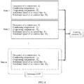
FIG. 1 is a flowchart of a linkage control method for indoor and outdoor units of a precision air conditioner according to an embodiment of the present invention; -
FIG. 2 is a diagram of an implementation principle of a method for controlling indoor and outdoor units of a precision air conditioner in the prior art; -
FIG. 3 is a diagram of an implementation principle of a linkage control method for indoor and outdoor units of a precision air conditioner according to an embodiment of the present invention; -
FIG. 4 is a diagram of an implementation principle of another linkage control method for indoor and outdoor units of a precision air conditioner according to an embodiment of the present invention; -
FIG. 5 is a diagram of an internal implementation principle of a linkage control apparatus for indoor and outdoor units of a precision air conditioner according to an embodiment of the present invention; and -
FIG. 6 is a diagram of an internal implementation principle of another linkage control apparatus for indoor and outdoor units of a precision air conditioner according to an embodiment of the present invention. - To make the objectives, technical solutions, and advantages of the embodiments of the present invention clearer, the following clearly and completely describes the technical solutions in the embodiments of the present invention with reference to the accompanying drawings in the embodiments of the present invention. Apparently, the described embodiments are some but not all of the embodiments of the present invention. All other embodiments obtained by a person of ordinary skill in the art based on the embodiments of the present invention without creative efforts shall fall within the protection scope of the present invention.
- A precision air conditioner is widely applicable to a high precision environment such as a computer equipment room, a program-controlled exchange equipment room, a mobile satellite communications station, or a data container. This environment has very strict requirements on indicators such as temperature, humidity, and airflow distribution of air, and needs to be ensured by a precision air conditioner device that is specific to an equipment room and that is running securely and reliably 24 hours a day, 365 days a year.
- The precision air conditioner is formed by connecting a compressor, a condenser located outdoor at downstream of the compressor, an evaporator located indoor at upstream of the compressor, an electronic expansion valve, and a throttle mechanism in the middle of the evaporator. The present invention is widely applicable to the high precision environment such as a computer equipment room, a program-controlled exchange equipment room, a mobile satellite communications station, or a data container, and is certainly also applicable to the field of households.
- A control logic of the existing precision air conditioner has three disadvantages: First, a rotational speed of a fan of the condenser depends only on a high-pressure sensor, and a rotational speed of a fan of the evaporator depends only on a temperature difference between an inlet and an outlet, but in a cooling system, the condenser and the evaporator are connected in series, and the correlation between the condenser and the evaporator is ignored during independent control over the fans of the condenser and the evaporator. Second, a control target of the indoor and outdoor fans is to meet a heat exchange capacity requirement and implement output of a required cooling capacity (for the evaporator) or liquefaction of a refrigerant (for the condenser), thereby restricting further COP optimization. Third, after cooling load is changed, processes such as adjustment of a rotational speed of the compressor, a change in pressure at an inlet of the condenser, and a change in the temperature difference between the inlet and the outlet of the evaporator need to be experienced, so that a control instruction can be transferred to the indoor and outdoor fans. The control process has a slow speed, and when the system is unstable, repeated fluctuations occur. A heat exchange capacity and a coefficient of performance of the fan of the air conditioner are a pair of mutually restrictive factors, and therefore, a target heat exchange capacity needs to be obtained by using a minimum fan rotational speed, so as to maximize the coefficient of performance.
- A coefficient of performance (COP) function of the air conditioner includes:

- A power function of the compressor includes: W1=f1(f, Tc, Te).
- A power function of the condenser includes: the power function of the condenser: W2=f2 (f, Tc, Te, Δt1, N).
- A power function of the evaporator includes: the power function of the evaporator:

- A target cooling capacity function of the compressor includes: Q=f0(f, Tc, Te).
- Using a model as an example, a cooling capacity of the compressor (6) may be calculated by using the following function (function (a)):

- Using a model as an example, a power of the compressor (6) may be calculated by using the following function (function (b)):

- Using a model as an example, a power function of the outdoor fan (the condenser (4)) is P1 =f (Voutdoor, N), where
Voutdoor is an air volume of an outdoor unit ((the condenser (4)), and Voutdoor=(Q+W1)/(c*ρ*Δt1). - Using a model as an example, a power function of the indoor fan is P2 =f (Vindoor, M), where
Vindoor is an air volume of an indoor unit evaporator (2), and Vindoor=Q/(c*ρ*Δt2), where
c is an air specific heat capacity, p is an air density, and Δt1 and Δt2 are air temperature differences between inlets and outlets of the condenser (4) and the evaporator (2). - As shown in
FIG. 1, FIG. 1 is a flowchart of a linkage control method for indoor and outdoor units of a precision air conditioner according to an embodiment of the present invention, and steps of this embodiment are as follows: - Step S101: Obtain temperature difference load of an evaporator and obtain, according to a PID algorithm, a target working frequency fn of a compressor, where the temperature difference load is a product of an air volume of the evaporator, an air temperature difference between an inlet and an outlet of the evaporator, and an air specific heat capacity.
- Step S102: Obtain a target cooling capacity Qn of the compressor according to a target cooling capacity function of the compressor and in combination with a condensing temperature Tcn, an evaporating temperature Ten, and fn in a current status, where the condensing temperature Tcn is a temperature of a refrigerant in a condenser, and the evaporating temperature Ten is a temperature of the refrigerant in the compressor; obtain a target power W1 of the compressor according to a power function of the compressor and in combination with the condensing temperature Tcn, the evaporating temperature Ten, and fn in the current status; obtain a target power W2 of the condenser according to a power function of the condenser and in combination with the condensing temperature Tcn, the evaporating temperature Ten, and fn in the current status, a temperature difference Δt1 between an inlet and an outlet of the condenser, and a rotational speed M of the condenser, where the rotational speed M of the condenser is obtained by a pressure sensor according to pressure of the refrigerant at a front end of the condenser; and obtain a target power W3 of the evaporator according to a power function of the evaporator and in combination with the condensing temperature Tcn, the evaporating temperature Ten, and fn in the current status, a temperature difference Δt2 between the inlet and the outlet of the evaporator, and a rotational speed N of the evaporator.
- Step S103: Optimize, in a range of Qn(±a%+1), the target working frequency fn, the condensing temperature Tcn, and the evaporating temperature Ten respectively in specified ranges according to a coefficient of performance (COP) function of the air conditioner, so as to obtain a target working frequency fnd, a target condensing temperature Tcnd, and a target evaporating temperature Tend when a COP value is maximum, where a is a preset natural number.
- Step S104: Adjust the rotational speed N of the evaporator according to a target temperature difference between the inlet and the outlet of the evaporator, control the compressor to run at the target working frequency fnd, and adjust the rotational speed M of the condenser according to the target condensing temperature Tcnd of the condenser, where the target temperature difference between the inlet and the outlet of the evaporator is Δt2-(Tend-Ten).
- Beneficial effects: by using a target of optimizing an overall coefficient of performance (COP) of an air conditioner system, a target working frequency fnd, a target condensing temperature Tcnd, and a target evaporating temperature Tend when a COP value is maximum are obtained, so that a technical solution of linkage control over rotational speeds of indoor and outdoor fans is implemented, and when the rotational speeds of the fans match a heat exchange capacity requirement, technical effects of fast adjustment and control, a low delay, and an optimum overall coefficient of performance of the air conditioner system are achieved.
- Further, the optimizing, in a range of Qn(±a%+1), the target working frequency fn, the condensing temperature Tcn, and the evaporating temperature Ten respectively in specified ranges according to a coefficient of performance (COP) function of the air conditioner, so as to obtain a target working frequency fnd, a target condensing temperature Tcnd, and a target evaporating temperature Tend when a COP value is maximum specifically includes:
- optimizing, in the range of Qn(±a%+1), the target working frequency fn, the condensing temperature Tcn, and the evaporating temperature Ten respectively in ranges fn±b Hz, Tcn±c°C, and Ten±d°C according to the coefficient of performance (COP) function of the air conditioner, so as to obtain the target working frequency fnd, the target condensing temperature Tcnd, and the target evaporating temperature Tend when the COP value is the maximum, where a, b, and c are preset constants. Using a model as an example, optimization ranges of f, Tc, and Te are:the optimization range of f: ±5 Hz;
- the optimization range of Tc: ±2°C; and
- the optimization range of Te: ±2°C.
-
FIG. 2 is a diagram of an implementation principle of a method for controlling indoor and outdoor units of a precision air conditioner in the prior art. - To adjust and control a rotational speed of a fan, in a precision air conditioner system, a pressure sensor is installed at an inlet end of a condenser, so as to detect pressure of a high-pressure gaseous refrigerant transmitted from a compressor (therefore, the pressure sensor is also referred to as a high-pressure sensor). A larger pressure value detected by the sensor indicates a higher saturation temperature of the refrigerant under the pressure, and further a higher heat exchange capacity that needs to be implemented by a heat exchanger, so that a rotational speed of a fan of the condenser needs to be increased; otherwise, the rotational speed of the fan needs to be decreased. For an evaporator, temperature sensors are installed at an inlet and an outlet that are along an air flow direction, so as to detect a temperature difference between air entering and air leaving the evaporator. For the evaporator, a product of an air specific heat capacity, an air temperature difference between the inlet and the outlet, and an air volume approximates to a constant. A smaller air temperature difference between the inlet and the outlet indicates a relatively greater air volume, so that a rotational speed of a fan of the evaporator needs to be decreased; otherwise, the rotational speed of the fan of the evaporator needs to be increased.
- By convention, a target control value of a rotational speed of the compressor is set according to temperature difference load. After the rotational speed of the compressor is adjusted to a target rotational speed, the rotational speed of the fan of the outdoor condenser is adjusted according to a pressure value of the high-pressure sensor, and the rotational speed of the fan of the indoor evaporator is adjusted according to the air temperature difference between the inlet and the outlet of the evaporator. That is, the rotational speed of the outdoor fan is determined by the high-pressure sensor, and the rotational speed of the indoor fan is determined by using the temperature difference between the inlet and the outlet. A control target is to make the rotational speeds of the fans match a heat exchange capacity requirement.
- A control logic of the existing precision air conditioner has three disadvantages: First, the rotational speed of the fan of the condenser depends only on the high-pressure sensor, and the rotational speed of the fan of the evaporator depends only on the temperature difference between the inlet and the outlet, but in the cooling system, the condenser and the evaporator are connected in series, and the correlation between the condenser and the evaporator is ignored during independent control over the fans of the condenser and the evaporator. Second, the control target of the indoor and outdoor fans is to meet the heat exchange capacity requirement and implement output of a required cooling capacity (for the evaporator) or liquefaction of the refrigerant (for the condenser), thereby restricting further COP optimization. Third, after cooling load is changed, processes such as adjustment of the rotational speed of the compressor, a change in pressure at the inlet of the condenser, and a change in the temperature difference between the inlet and the outlet of the evaporator need to be experienced, so that a control instruction can be transferred to the indoor and outdoor fans. The control process has a slow speed, and when the system is unstable, repeated fluctuations occur.
-
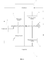
FIG. 3 is a diagram of an implementation principle of a linkage control method for indoor and outdoor units of a precision air conditioner according to an embodiment of the present invention. In the figure, an outdoor fan is a fan of a condenser, and an indoor fan is a fan of an evaporator. - After a target working frequency fn of a compressor is obtained according to temperature difference load of the evaporator and a PID algorithm, the method does not need to be performed as shown in
FIG. 2 , so as to avoid obtaining high pressure, low pressure, and temperatures of indoor and outdoor units only when a working frequency of the compressor starts to be adjusted or when the target working frequency fn is obtained through adjustment, and then obtaining a rotational speed of the outdoor fan according to the high pressure and obtaining a rotational speed of the indoor fan according to the temperature. In this embodiment of the present invention, after the target working frequency fn of the compressor is obtained according to the temperature difference load of the evaporator and the PID algorithm, a target cooling capacity Qn of the compressor is directly obtained according to a target cooling capacity function of the compressor and in combination with a condensing temperature Tcn, an evaporating temperature Ten, and fn in a current status. The condensing temperature Tcn is a temperature of a refrigerant in a condenser, and the evaporating temperature Ten is a temperature of the refrigerant in the compressor. A target power W1 of the compressor is obtained according to a power function of the compressor and in combination with the condensing temperature Tcn, the evaporating temperature Ten, and fn in the current status. A target power W2 of the condenser is obtained according to a power function of the condenser and in combination with the condensing temperature Tcn, the evaporating temperature Ten, and fn in the current status, a temperature difference Δt1 between an inlet and an outlet of the condenser, and a rotational speed M of the condenser. The rotational speed M of the condenser is obtained by a pressure sensor according to pressure of the refrigerant at a front end of the condenser. A target power W3 of the evaporator is obtained according to a power function of the evaporator and in combination with the condensing temperature Tcn, the evaporating temperature Ten, and fn in the current status, a temperature difference Δt2 between the inlet and the outlet of the evaporator, and a rotational speed N of the evaporator. - In a range of Qn(±a%+1), the target working frequency fn, the condensing temperature Tcn, and the evaporating temperature Ten are optimized respectively in specified ranges according to a coefficient of performance (COP) function of the air conditioner, so as to obtain a target working frequency fnd, a target condensing temperature Tcnd, and a target evaporating temperature Tend when a COP value is maximum, where a is a preset natural number. Using a model as an example, optimization ranges of f, Tc, and Te are:
- the optimization range of f: ±5 Hz;
- the optimization range of Tc: ±2°C; and
- the optimization range of Te: ±2°C.
- The rotational speed N of the evaporator is adjusted according to a target temperature difference between the inlet and the outlet of the evaporator, the compressor is controlled to run at the target working frequency fnd, and the rotational speed M of the condenser is adjusted according to the target condensing temperature Tcnd of the condenser. The target temperature difference between the inlet and the outlet of the evaporator is Δt2-(Tend-Ten).
- Beneficial effects: by using a target of optimizing an overall coefficient of performance (COP) of an air conditioner system, a target working frequency fnd, a target condensing temperature Tcnd, and a target evaporating temperature Tend when a COP value is maximum are obtained, so that a technical solution of linkage control over rotational speeds of indoor and outdoor fans is implemented, and when the rotational speeds of the fans match a heat exchange capacity requirement, technical effects of fast adjustment and control, a low delay, and an optimum overall coefficient of performance of the air conditioner system are achieved.
-
FIG. 4 is a diagram of an implementation principle of another linkage control method for indoor and outdoor units of a precision air conditioner according to an embodiment of the present invention. In the figure, an outdoor fan is a fan of a condenser, and an indoor fan is a fan of an evaporator. - A working state of a precision air conditioner system is determined by a combination of state parameters such as a working frequency f of a compressor, a condensing temperature Tc, an evaporating temperature Te, a rotational speed M of an outdoor fan, and a rotational speed N of an indoor fan. As shown in
FIG. 4 , when a cooling capacity of an air conditioning unit is Q, there are n different combinations of working states for the unit: (f1, Tc1, Te1, N1, M1) ... (fn, Tcn, Ten, Nn, Mn). The working states are corresponding to different system COPs, and in all the combinations, only one state combination (fn, Tcn, Ten, Nn, Mn) is corresponding to an optimum coefficient of performance (COP) value of the air conditioner. Using a model as an example, optimization ranges of f, Tc, and Te are: - the optimization range of f: ±5 Hz;
- the optimization range of Tc: ±2°C; and
- the optimization range of Te: ±2°C.
- In the present invention, a specified range is set for each parameter, and in the various states of the air conditioner or the air conditioning unit, when the coefficient of performance (COP ) value of the air conditioner is optimum, a value of each parameter is obtained. The rotational speed N of the evaporator is adjusted according to a target temperature difference between an inlet and an outlet of the evaporator, the compressor is controlled to run at a target working frequency fnd, and the rotational speed M of the condenser is adjusted according to a target condensing temperature Tcnd of the condenser. The target temperature difference between the inlet and the outlet of the evaporator is Δt2-(Tend-Ten). Therefore, a target coefficient of performance of the air conditioner becomes optimum.
- Beneficial effects: by using a target of optimizing an overall coefficient of performance (COP) of an air conditioner system, a target working frequency fnd, a target condensing temperature Tcnd, and a target evaporating temperature Tend when a COP value is maximum are obtained, so that a technical solution of linkage control over rotational speeds of indoor and outdoor fans is implemented, and, when the rotational speeds of the fans match a heat exchange capacity requirement, technical effects of fast adjustment and control, a low delay, and an optimum overall coefficient of performance of the air conditioner system are achieved.
-
FIG. 5 is a diagram of an internal implementation principle of a linkage control apparatus for indoor and outdoor units of a precision air conditioner according to an embodiment of the present invention. The apparatus includes: - a temperature sensor (1), configured to obtain an air temperature difference between an inlet and an outlet of an evaporator (2);
- a pressure sensor (3), configured to obtain pressure of a refrigerant at a front end of a condenser (4), so as to adjust a rotational speed M of a fan of the condenser (4);
- a processor (5), configured to obtain a target working frequency fn of a compressor (6) according to temperature difference load of the evaporator (2) and a PID algorithm, where the temperature difference load is a product of an air volume of the evaporator (2), the air temperature difference between the inlet and the outlet of the evaporator (2), and an air specific heat capacity, where the air volume of the evaporator (2) is a volume of air that flows through the evaporator (2) per unit time, where
- the processor (5) is further configured to obtain a target cooling capacity Qn of the compressor according to a target cooling capacity function of the compressor (6) and in combination with a condensing temperature Tcn, an evaporating temperature Ten, and fn in a current status, where the condensing temperature Tcn is a temperature of the refrigerant in the condenser (4), and the evaporating temperature Ten is a temperature of the refrigerant in the compressor (6);
- the processor (5) is further configured to obtain a target power W1 of the compressor (6) according to a power function of the compressor (6) and in combination with the condensing temperature Tcn, the evaporating temperature Ten, and fn in the current status;
- the processor (5) is further configured to obtain a target power W2 of the condenser (4) according to a power function of the condenser (4) and in combination with the condensing temperature Tcn, the evaporating temperature Ten, and fn in the current status, a temperature difference Δt1 between an inlet and an outlet of the condenser (4), and the rotational speed M of the condenser (4);
- the processor (5) is further configured to obtain a target power W3 of the evaporator (2) according to a power function of the evaporator (2) and in combination with the condensing temperature Tcn, the evaporating temperature Ten, and fn in the current status, a temperature difference Δt2 between the inlet and the outlet of the evaporator (2), and a rotational speed N of the evaporator (2), where the rotational speed N of the evaporator (2) is determined by the temperature sensor (1) according to the air temperature difference between the inlet and the outlet of the evaporator (2);
- the processor (5) is further configured to: optimize, in a range of Qn(±a%+1), the target working frequency fn, the condensing temperature Tcn, and the evaporating temperature Ten respectively in specified ranges according to a coefficient of performance (COP) function of the air conditioner, so as to obtain a target working frequency fnd, a target condensing temperature Tcnd, and a target evaporating temperature Tend when a COP value is maximum, where a is a preset natural number; and
- the processor (5) is further configured to adjust the rotational speed N of the evaporator (2) according to a target temperature difference between the inlet and the outlet of the evaporator (2), control the compressor (6) to run at the target working frequency fnd, and adjust the rotational speed M of the condenser (4) according to the target condensing temperature Tcnd of the condenser (4), where the target temperature difference between the inlet and the outlet of the evaporator (2) is Δt2-(Tend-Ten); and
- a memory (7), configured to store the foregoing data and programs.
- The foregoing apparatuses and modules are connected by using a bus (8).
- Beneficial effects: by using a target of optimizing an overall coefficient of performance (COP) of an air conditioner system, a target working frequency fnd, a target condensing temperature Tcnd, and a target evaporating temperature Tend when a COP value is maximum are obtained, so that a technical solution of linkage control over rotational speeds of indoor and outdoor fans is implemented, and when the rotational speeds of the fans match a heat exchange capacity requirement, technical effects of fast adjustment and control, a low delay, and an optimum overall coefficient of performance of the air conditioner system are achieved.
- Further, the optimizing, in a range of Qn(±a%+1), the target working frequency fn, the condensing temperature Tcn, and the evaporating temperature Ten respectively in specified ranges according to a coefficient of performance (COP) function of the air conditioner, so as to obtain a target working frequency fnd, a target condensing temperature Tcnd, and a target evaporating temperature Tend when a COP value is maximum specifically includes:
- the processor (5) is configured to: optimizing, in the range of Qn(±a%+1), the target working frequency fn, the condensing temperature Tcn, and the evaporating temperature Ten respectively in ranges fn±b Hz, Tcn±c°C, and Ten±d°C according to the coefficient of performance (COP) function of the air conditioner, so as to obtain the target working frequency fnd, the target condensing temperature Tcnd, and the target evaporating temperature Tend when the COP value is the maximum, where a, b, and c are preset constants.
- Using a model as an example, optimization ranges of f, Tc, and Te are:
- the optimization range of f: ±5 Hz;
- the optimization range of Tc: ±2°C; and
- the optimization range of Te: ±2°C.
-
FIG. 6 is a diagram of an internal implementation principle of another linkage control apparatus for indoor and outdoor units of a precision air conditioner according to an embodiment of the present invention. The apparatus includes: - a temperature sensor module (1), configured to obtain an air temperature difference between an inlet and an outlet of an evaporator (2);
- a pressure sensor module (3), configured to obtain pressure of a refrigerant at a front end of a condenser (4), so as to adjust a rotational speed M of a fan of the condenser (4);
- a processing module (5), configured to obtain a target working frequency fn of a compressor (6) according to temperature difference load of the evaporator (2) and a PID algorithm, where the temperature difference load is a product of an air volume of the evaporator (2), the air temperature difference between the inlet and the outlet of the evaporator (2), and an air specific heat capacity, where the air volume of the evaporator (2) is a volume of air that flows through the evaporator (2) per unit time, where
- the processing module (5) is further configured to obtain a target cooling capacity Qn of the compressor according to a target cooling capacity function of the compressor (6) and in combination with a condensing temperature Tcn, an evaporating temperature Ten, and fn in a current status, where the condensing temperature Tcn is a temperature of the refrigerant in the condenser (4), and the evaporating temperature Ten is a temperature of the refrigerant in the compressor (6);
- the processing module (5) is further configured to obtain a target power W1 of the compressor (6) according to a power function of the compressor (6) and in combination with the condensing temperature Tcn, the evaporating temperature Ten, and fn in the current status;
- the processing module (5) is further configured to obtain a target power W2 of the condenser (4) according to a power function of the condenser (4) and in combination with the condensing temperature Tcn, the evaporating temperature Ten, and fn in the current status, a temperature difference Δt1 between an inlet and an outlet of the condenser (4), and the rotational speed M of the condenser (4);
- the processing module (5) is further configured to obtain a target power W3 of the evaporator (2) according to a power function of the evaporator (2) and in combination with the condensing temperature Tcn, the evaporating temperature Ten, and fn in the current status, a temperature difference Δt2 between the inlet and the outlet of the evaporator (2), and a rotational speed N of the evaporator (2), where the rotational speed N of the evaporator (2) is determined by the temperature sensor module (1) according to the air temperature difference between the inlet and the outlet of the evaporator (2);
- the processing module (5) is further configured to: optimize, in a range of Qn(±a%+1), the target working frequency fn, the condensing temperature Tcn, and the evaporating temperature Ten respectively in specified ranges according to a coefficient of performance (COP) function of the air conditioner, so as to obtain a target working frequency fnd, a target condensing temperature Tcnd, and a target evaporating temperature Tend when a COP value is maximum, where a is a preset natural number; and
- the processing module (5) is further configured to adjust the rotational speed N of the evaporator (2) according to a target temperature difference between the inlet and the outlet of the evaporator (2), control the compressor (6) to run at the target working frequency fnd, and adjust the rotational speed M of the condenser (4) according to the target condensing temperature Tcnd of the condenser (4), where the target temperature difference between the inlet and the outlet of the evaporator (2) is Δt2-(Tend-Ten);
- and specifically, to adjust and control the rotational speeds of the fans, in a precision air conditioner system, a pressure sensor is installed at an inlet end of the condenser, so as to detect pressure of a high-pressure gaseous refrigerant transmitted from the compressor (therefore, the pressure sensor is also referred to as a high-pressure sensor); a larger pressure value detected by the sensor indicates a higher saturation temperature of the refrigerant under the pressure, and further a higher heat exchange capacity that needs to be implemented by a heat exchanger, so that the rotational speed of the fan of the condenser needs to be increased; otherwise, the rotational speed of the fan needs to be decreased; for an evaporator, temperature sensors are installed at an inlet and an outlet that are along an air flow direction, so as to detect a temperature difference between air entering and air leaving the evaporator; for the evaporator, a product of an air specific heat capacity, an air temperature difference between the inlet and the outlet, and an air volume approximates to a constant; and a smaller air temperature difference between the inlet and the outlet indicates a relatively greater air volume, so that the rotational speed of the fan of the evaporator needs to be decreased; otherwise, the rotational speed of the fan of the evaporator needs to be increased; and
- a storage module (7), configured to store the foregoing data and programs.
- The foregoing apparatuses and modules are connected by using a bus (8).
- Beneficial effects: by using a target of optimizing an overall coefficient of performance (COP) of an air conditioner system, a target working frequency fnd, a target condensing temperature Tcnd, and a target evaporating temperature Tend when a COP value is maximum are obtained, so that a technical solution of linkage control over rotational speeds of indoor and outdoor fans is implemented, and when the rotational speeds of the fans match a heat exchange capacity requirement, technical effects of fast adjustment and control, a low delay, and an optimum overall coefficient of performance of the air conditioner system are achieved.
- Further, the optimizing, in a range of Qn(±a%+1), the target working frequency fn, the condensing temperature Tcn, and the evaporating temperature Ten respectively in specified ranges according to a coefficient of performance (COP) function of the air conditioner, so as to obtain a target working frequency fnd, a target condensing temperature Tcnd, and a target evaporating temperature Tend when a COP value is maximum specifically includes:
- the processing module (5) is configured to: optimizing, in the range of Qn(±a%+1), the target working frequency fn, the condensing temperature Tcn, and the evaporating temperature Ten respectively in ranges fn±b Hz, Tcn±c°C, and Ten±d°C according to the coefficient of performance (COP) function of the air conditioner, so as to obtain the target working frequency fnd, the target condensing temperature Tcnd, and the target evaporating temperature Tend when the COP value is the maximum, where a, b, and c are preset constants.
- Using a model as an example, optimization ranges of f, Tc, and Te are:
- the optimization range of f: ±5 Hz;
- the optimization range of Tc: ±2°C; and
- the optimization range of Te: ±2°C.
- The present invention may be implemented in a plurality of implementation manners. The embodiments of the present invention may be executed by a specific software or hardware component. A person skilled in the art considers that different software or hardware combinations may also be applied to execute the embodiments of the present invention, and that the specific operations executed by hardware may also be implemented by software.
- Finally, it should be noted that the foregoing embodiments are merely intended for describing the technical solutions of the present invention, but not for limiting the present invention. Although the present invention is described in detail with reference to the foregoing embodiments, a person of ordinary skill in the art should understand that they may still make modifications to the technical solutions described in the foregoing embodiments or make equivalent replacements to some or all technical features thereof, without departing from the scope of the technical solutions of the embodiments of the present invention.
Claims (21)
- A linkage control method for indoor and outdoor units of a precision air conditioner, comprising:obtaining temperature difference load of an evaporator and obtaining, according to a PID algorithm, a target working frequency fn of a compressor, wherein the temperature difference load is a product of an air volume of the evaporator, an air temperature difference between an inlet and an outlet of the evaporator, and an air specific heat capacity, wherein the air volume of the evaporator is a volume of air that flows through the evaporator per unit time;obtaining a target cooling capacity Qn of the compressor according to a target cooling capacity function of the compressor and in combination with a condensing temperature Tcn, an evaporating temperature Ten, and fn in a current status, wherein the condensing temperature Tcn is a temperature of a refrigerant in a condenser, and the evaporating temperature Ten is a temperature of the refrigerant in the compressor; obtaining a target power W1 of the compressor according to a power function of the compressor and in combination with the condensing temperature Tcn, the evaporating temperature Ten, and fn in the current status; obtaining a target power W2 of the condenser according to a power function of the condenser and in combination with the condensing temperature Tcn, the evaporating temperature Ten, and fn in the current status, a temperature difference Δt1 between an inlet and an outlet of the condenser, and a rotational speed M of the condenser, wherein the rotational speed M of the condenser is obtained by a pressure sensor according to pressure of the refrigerant at a front end of the condenser; and obtaining a target power W3 of the evaporator according to a power function of the evaporator and in combination with the condensing temperature Tcn, the evaporating temperature Ten, and fn in the current status, a temperature difference Δt2 between the inlet and the outlet of the evaporator, and a rotational speed N of the evaporator;optimizing, in a range of Qn(±a%+1), the target working frequency fn, the condensing temperature Tcn, and the evaporating temperature Ten respectively in specified ranges according to a coefficient of performance (COP) function of the air conditioner, so as to obtain a target working frequency fnd, a target condensing temperature Tcnd, and a target evaporating temperature Tend when a COP value is maximum, wherein the 'a' is a preset natural number; andadjusting the rotational speed N of the evaporator according to a target temperature difference between the inlet and the outlet of the evaporator, controlling the compressor to run at the target working frequency fnd, and adjusting the rotational speed M of the condenser according to the target condensing temperature Tcnd of the condenser, wherein the target temperature difference between the inlet and the outlet of the evaporator is Δt2-(Tend-Ten).
- The method according to claim 1, wherein the coefficient of performance (COP) function of the air conditioner comprises:

- The method according to claim 1 or 2, wherein the power function of the compressor comprises:

- The method according to claim 3, wherein the power function of the condenser comprises:

- The method according to any one of claims 1 to 4, wherein the power function of the evaporator comprises:

- The method according to any one of claims 1 to 5, wherein the target cooling capacity function of the compressor comprises:

- The method according to any one of claims 1 to 6, wherein the optimizing, in a range of Qn(±a%+1), the target working frequency fn, the condensing temperature Tcn, and the evaporating temperature Ten respectively in specified ranges according to a coefficient of performance (COP) function of the air conditioner, so as to obtain a target working frequency fnd, a target condensing temperature Tcnd, and a target evaporating temperature Tend when a COP value is maximum specifically comprises:optimizing, in the range of Qn(±a%+1), the target working frequency fn, the condensing temperature Tcn, and the evaporating temperature Ten respectively in ranges fn±b Hz, Tcn±c°C, and Ten±d°C according to the coefficient of performance (COP) function of the air conditioner, so as to obtain the target working frequency fnd, the target condensing temperature Tcnd, and the target evaporating temperature Tend when the COP value is the maximum, wherein a, b, and c are preset constants.
- A linkage control apparatus for indoor and outdoor units of a precision air conditioner, comprising:a temperature sensor (1), configured to obtain an air temperature difference between an inlet and an outlet of an evaporator (2);a pressure sensor (3), configured to obtain pressure of a refrigerant at a front end of a condenser (4), so as to adjust a rotational speed M of a fan of the condenser (4);a processor (5), configured to obtain a target working frequency fn of a compressor (6) according to temperature difference load of the evaporator (2) and a PID algorithm, wherein the temperature difference load is a product of an air volume of the evaporator (2), the air temperature difference between the inlet and the outlet of the evaporator (2), and an air specific heat capacity, wherein the air volume of the evaporator (2) is a volume of air that flows through the evaporator (2) per unit time, whereinthe processor (5) is further configured to obtain a target cooling capacity Qn of the compressor according to a target cooling capacity function of the compressor (6) and in combination with a condensing temperature Tcn, an evaporating temperature Ten, and fn in a current status, wherein the condensing temperature Tcn is a temperature of the refrigerant in the condenser (4), and the evaporating temperature Ten is a temperature of the refrigerant in the compressor (6);the processor (5) is further configured to obtain a target power W1 of the compressor (6) according to a power function of the compressor (6) and in combination with the condensing temperature Tcn, the evaporating temperature Ten, and fn in the current status;the processor (5) is further configured to obtain a target power W2 of the condenser (4) according to a power function of the condenser (4) and in combination with the condensing temperature Tcn, the evaporating temperature Ten, and fn in the current status, a temperature difference Δt1 between an inlet and an outlet of the condenser (4), and the rotational speed M of the condenser (4);the processor (5) is further configured to obtain a target power W3 of the evaporator (2) according to a power function of the evaporator (2) and in combination with the condensing temperature Tcn, the evaporating temperature Ten, and fn in the current status, a temperature difference Δt2 between the inlet and the outlet of the evaporator (2), and a rotational speed N of the evaporator (2), wherein the rotational speed N of the evaporator (2) is determined by the temperature sensor (1) according to the air temperature difference between the inlet and the outlet of the evaporator (2);the processor (5) is further configured to: optimize, in a range of Qn(±a%+1), the target working frequency fn, the condensing temperature Tcn, and the evaporating temperature Ten respectively in specified ranges according to a coefficient of performance (COP) function of the air conditioner, so as to obtain a target working frequency fnd, a target condensing temperature Tcnd, and a target evaporating temperature Tend when a COP value is maximum, wherein the 'a' is a preset natural number; andthe processor (5) is further configured to adjust the rotational speed N of the evaporator (2) according to a target temperature difference between the inlet and the outlet of the evaporator (2), control the compressor (6) to run at the target working frequency fnd, and adjust the rotational speed M of the condenser (4) according to the target condensing temperature Tcnd of the condenser (4), wherein the target temperature difference between the inlet and the outlet of the evaporator (2) is Δt2-(Tend-Ten); anda memory (7), configured to store the foregoing data and programs.
- The apparatus according to claim 8, wherein the coefficient of performance (COP) function of the air conditioner comprises:

- The apparatus according to claim 8 or 9, wherein the power function of the compressor (6) comprises:

- The method according to claim 10, wherein the power function of the condenser comprises:

- The apparatus according to any one of claims 8 to 11, wherein the power function of the evaporator comprises:

- The apparatus according to any one of claims 8 to 12, wherein the target cooling capacity function of the compressor (6) comprises:

- The apparatus according to any one of claims 8 to 13, wherein the optimizing, in a range of Qn(±a%+1), the target working frequency fn, the condensing temperature Tcn, and the evaporating temperature Ten respectively in specified ranges according to a coefficient of performance (COP) function of the air conditioner, so as to obtain a target working frequency fnd, a target condensing temperature Tcnd, and a target evaporating temperature Tend when a COP value is maximum specifically comprises:optimizing, in the range of Qn(±a%+1), the target working frequency fn, the condensing temperature Tcn, and the evaporating temperature Ten respectively in ranges fn±b Hz, Tcn±c°C, and Ten±d°C according to the coefficient of performance (COP) function of the air conditioner, so as to obtain the target working frequency fnd, the target condensing temperature Tcnd, and the target evaporating temperature Tend when the COP value is the maximum, wherein a, b, and c are preset constants.
- A linkage control apparatus for indoor and outdoor units of a precision air conditioner, comprising:a temperature sensor module (1), configured to obtain an air temperature difference between an inlet and an outlet of an evaporator (2);a pressure sensor module (3), configured to obtain pressure of a refrigerant at a front end of a condenser (4), so as to adjust a rotational speed M of a fan of the condenser (4);a processing module (5), configured to obtain a target working frequency fn of a compressor (6) according to temperature difference load of the evaporator (2) and a PID algorithm, wherein the temperature difference load is a product of an air volume of the evaporator (2), the air temperature difference between the inlet and the outlet of the evaporator (2), and an air specific heat capacity, wherein the air volume of the evaporator (2) is a volume of air that flows through the evaporator (2) per unit time, whereinthe processing module (5) is further configured to obtain a target cooling capacity Qn of the compressor according to a target cooling capacity function of the compressor (6) and in combination with a condensing temperature Tcn, an evaporating temperature Ten, and fn in a current status, wherein the condensing temperature Tcn is a temperature of the refrigerant in the condenser (4), and the evaporating temperature Ten is a temperature of the refrigerant in the compressor (6);the processing module (5) is further configured to obtain a target power W1 of the compressor (6) according to a power function of the compressor (6) and in combination with the condensing temperature Tcn, the evaporating temperature Ten, and fn in the current status;the processing module (5) is further configured to obtain a target power W2 of the condenser (4) according to a power function of the condenser (4) and in combination with the condensing temperature Tcn, the evaporating temperature Ten, and fn in the current status, a temperature difference Δt1 between an inlet and an outlet of the condenser (4), and the rotational speed M of the condenser (4);the processing module (5) is further configured to obtain a target power W3 of the evaporator (2) according to a power function of the evaporator (2) and in combination with the condensing temperature Tcn, the evaporating temperature Ten, and fn in the current status, a temperature difference Δt2 between the inlet and the outlet of the evaporator (2), and a rotational speed N of the evaporator (2), wherein the rotational speed N of the evaporator (2) is determined by the temperature sensor module (1) according to the air temperature difference between the inlet and the outlet of the evaporator (2);the processing module (5) is further configured to: optimize, in a range of Qn(±a%+1), the target working frequency fn, the condensing temperature Tcn, and the evaporating temperature Ten respectively in specified ranges according to a coefficient of performance (COP) function of the air conditioner, so as to obtain a target working frequency fnd, a target condensing temperature Tcnd, and a target evaporating temperature Tend when a COP value is maximum, wherein the 'a' is a preset natural number; andthe processing module (5) is further configured to adjust the rotational speed N of the evaporator (2) according to a target temperature difference between the inlet and the outlet of the evaporator (2), control the compressor (6) to run at the target working frequency fnd, and adjust the rotational speed M of the condenser (4) according to the target condensing temperature Tcnd of the condenser (4), wherein the target temperature difference between the inlet and the outlet of the evaporator (2) is Δt2-(Tend-Ten); anda storage module (7), configured to store the foregoing data and programs.
- The apparatus according to claim 15, wherein the coefficient of performance (COP) function of the air conditioner comprises:

- The apparatus according to claim 15 or 16, wherein the power function of the compressor (6) comprises:

- The apparatus according to claim 17, wherein the power function of the condenser comprises:

- The apparatus according to any one of claims 15 to 18, wherein the power function of the evaporator comprises:

- The apparatus according to any one of claims 15 to 19, wherein the target cooling capacity function of the compressor (6) comprises:

- The apparatus according to any one of claims 15 to 20, wherein the optimizing, in a range of Qn(±a%+1), the target working frequency fn, the condensing temperature Tcn, and the evaporating temperature Ten respectively in specified ranges according to a coefficient of performance (COP) function of the air conditioner, so as to obtain a target working frequency fnd, a target condensing temperature Tcnd, and a target evaporating temperature Tend when a COP value is maximum specifically comprises:optimizing, in the range of Qn(±a%+1), the target working frequency fn, the condensing temperature Tcn, and the evaporating temperature Ten respectively in ranges fn±b Hz, Tcn±c°C, and Ten±d°C according to the coefficient of performance (COP) function of the air conditioner, so as to obtain the target working frequency fnd, the target condensing temperature Tcnd, and the target evaporating temperature Tend when the COP value is the maximum, wherein a, b, and c are preset constants.
Applications Claiming Priority (1)
| Application Number | Priority Date | Filing Date | Title |
|---|---|---|---|
| CN201610134164.2A CN105757888B (en) | 2016-03-09 | 2016-03-09 | The control method and device of machine linkage inside and outside a kind of precision air conditioner |
Publications (3)
| Publication Number | Publication Date |
|---|---|
| EP3228958A2 true EP3228958A2 (en) | 2017-10-11 |
| EP3228958A3 EP3228958A3 (en) | 2017-11-01 |
| EP3228958B1 EP3228958B1 (en) | 2021-05-19 |
Family
ID=56332882
Family Applications (1)
| Application Number | Title | Priority Date | Filing Date |
|---|---|---|---|
| EP17160108.1A Active EP3228958B1 (en) | 2016-03-09 | 2017-03-09 | Linkage control method and apparatus for indoor and outdoor units of precision air conditioner |
Country Status (2)
| Country | Link |
|---|---|
| EP (1) | EP3228958B1 (en) |
| CN (1) | CN105757888B (en) |
Cited By (5)
| Publication number | Priority date | Publication date | Assignee | Title |
|---|---|---|---|---|
| WO2020249579A1 (en) * | 2019-06-14 | 2020-12-17 | Valeo Systemes Thermiques | Method for managing a thermal management device for a motor vehicle and associated thermal management device |
| CN112815571A (en) * | 2021-01-18 | 2021-05-18 | 中科广能能源研究院(重庆)有限公司 | Rotating speed regulation control method and system for gas heat pump engine driving compressor |
| CN113932366A (en) * | 2021-11-02 | 2022-01-14 | 珠海格力电器股份有限公司 | Control method of kitchen air conditioner and air conditioner |
| CN114110957A (en) * | 2020-08-28 | 2022-03-01 | 广东美的制冷设备有限公司 | Wind frequency linkage control method and device, air conditioner and storage medium |
| WO2023099431A1 (en) * | 2021-12-01 | 2023-06-08 | BSH Hausgeräte GmbH | Refrigeration device and method for operating a refrigeration device |
Families Citing this family (15)
| Publication number | Priority date | Publication date | Assignee | Title |
|---|---|---|---|---|
| CN106247655B (en) * | 2016-07-25 | 2019-03-08 | 华为技术有限公司 | A kind of underloading desiccant cooling method and device |
| DE102017204122B4 (en) | 2017-03-13 | 2020-07-16 | Audi Ag | Method for operating a refrigerant circuit for a vehicle air conditioning system |
| CN107084479B (en) * | 2017-04-13 | 2020-02-04 | 青岛海尔空调器有限总公司 | Heating operation control method for air conditioner |
| CN110360704A (en) * | 2018-04-09 | 2019-10-22 | 珠海格力电器股份有限公司 | The compensation method of air conditioner connecting pipe pressure loss and device |
| CN109237751B (en) * | 2018-07-25 | 2021-06-11 | 广东芬尼能源技术有限公司 | Method, device, equipment and medium for quickly achieving unit target capacity |
| CN110940059B (en) * | 2018-09-21 | 2020-11-24 | 珠海格力电器股份有限公司 | Air conditioning equipment control method, device and equipment |
| CN110822658B (en) * | 2019-11-14 | 2021-04-20 | 南京晶华智能科技有限公司 | Air conditioner control method and device |
| CN111023408B (en) * | 2019-11-25 | 2021-06-15 | 顿汉布什(中国)工业有限公司 | Air conditioning unit design calculation and matched software compiling method |
| CN111059727A (en) * | 2019-12-06 | 2020-04-24 | 徐州顺风阀门有限公司 | Frequency control method for air conditioner compressor |
| CN111829146B (en) * | 2020-06-11 | 2022-04-05 | 华帝股份有限公司 | Control method of kitchen air conditioner |
| CN113076670B (en) * | 2021-03-26 | 2022-10-18 | 贵州航天电子科技有限公司 | Multi-physical-field coupled phased array guidance micro-system collaborative optimization method |
| CN113865257B (en) * | 2021-10-11 | 2023-01-20 | 珠海格力电器股份有限公司 | Refrigerator control method, device and system and refrigerator |
| CN114857757A (en) * | 2022-03-31 | 2022-08-05 | 青岛海尔空调器有限总公司 | Method and device for controlling air conditioner, air conditioner and storage medium |
| CN114659236B (en) * | 2022-04-29 | 2023-11-21 | 深圳市英维克信息技术有限公司 | Energy-saving control method, device, equipment and storage medium |
| CN116518600A (en) * | 2023-07-05 | 2023-08-01 | 中建环能科技股份有限公司 | Control method for refrigerating performance of compressor of heat pump low-temperature drying equipment and electronic equipment |
Family Cites Families (7)
| Publication number | Priority date | Publication date | Assignee | Title |
|---|---|---|---|---|
| US9239174B2 (en) * | 2011-02-17 | 2016-01-19 | Rocky Research | Cascade floating intermediate temperature heat pump system |
| US8793003B2 (en) * | 2011-03-31 | 2014-07-29 | Mitsubishi Electric Research Laboratories, Inc. | Controlling operations of vapor compression system |
| JP5370560B2 (en) * | 2011-09-30 | 2013-12-18 | ダイキン工業株式会社 | Refrigerant cycle system |
| KR101389573B1 (en) * | 2013-02-01 | 2014-05-12 | (주) 대호아이앤티 | System for linkage wireless communication using copper tube communication |
| US20140345307A1 (en) * | 2013-05-23 | 2014-11-27 | Air To Water Technologies, Inc. | Energy efficient dehumidifying refrigeration system |
| CN104515245B (en) * | 2013-09-26 | 2017-06-30 | 珠海格力电器股份有限公司 | The control method and device of air-conditioning system |
| CN104864572A (en) * | 2015-06-08 | 2015-08-26 | 珠海格力电器股份有限公司 | Air conditioner control method and device |
-
2016
- 2016-03-09 CN CN201610134164.2A patent/CN105757888B/en active Active
-
2017
- 2017-03-09 EP EP17160108.1A patent/EP3228958B1/en active Active
Non-Patent Citations (1)
| Title |
|---|
| None |
Cited By (7)
| Publication number | Priority date | Publication date | Assignee | Title |
|---|---|---|---|---|
| WO2020249579A1 (en) * | 2019-06-14 | 2020-12-17 | Valeo Systemes Thermiques | Method for managing a thermal management device for a motor vehicle and associated thermal management device |
| FR3097310A1 (en) * | 2019-06-14 | 2020-12-18 | Valeo Systemes Thermiques | Method of managing a thermal management device for a motor vehicle and associated thermal management device. |
| CN114110957A (en) * | 2020-08-28 | 2022-03-01 | 广东美的制冷设备有限公司 | Wind frequency linkage control method and device, air conditioner and storage medium |
| CN114110957B (en) * | 2020-08-28 | 2023-06-30 | 广东美的制冷设备有限公司 | Wind frequency linkage control method and device, air conditioner and storage medium |
| CN112815571A (en) * | 2021-01-18 | 2021-05-18 | 中科广能能源研究院(重庆)有限公司 | Rotating speed regulation control method and system for gas heat pump engine driving compressor |
| CN113932366A (en) * | 2021-11-02 | 2022-01-14 | 珠海格力电器股份有限公司 | Control method of kitchen air conditioner and air conditioner |
| WO2023099431A1 (en) * | 2021-12-01 | 2023-06-08 | BSH Hausgeräte GmbH | Refrigeration device and method for operating a refrigeration device |
Also Published As
| Publication number | Publication date |
|---|---|
| EP3228958A3 (en) | 2017-11-01 |
| CN105757888A (en) | 2016-07-13 |
| CN105757888B (en) | 2019-09-20 |
| EP3228958B1 (en) | 2021-05-19 |
Similar Documents
| Publication | Publication Date | Title |
|---|---|---|
| EP3228958A2 (en) | Linkage control method and apparatus for indoor and outdoor units of precision air conditioner | |
| CN110671777B (en) | Control method and device of air conditioner and air conditioner | |
| US10119717B2 (en) | Heat source system, and device and method for controlling cooling water supply device | |
| US9206994B2 (en) | Heat source system | |
| US8825184B2 (en) | Multivariable optimization of operation of vapor compression systems | |
| CN105588256B (en) | A kind of control method and device of VRF Air Conditioning System | |
| US9562701B2 (en) | Temperature control system and air conditioning system | |
| RU2680447C1 (en) | Steam compression system with at least two external installations | |
| EP3293467A1 (en) | Light-load dehumidification and refrigeration method and device | |
| CN106225361A (en) | Aperture control method, device and the frequency changing refrigeration system of a kind of electric expansion valve | |
| US8694131B2 (en) | System and method for controlling operations of vapor compression system | |
| CN102213475A (en) | Adaptive management method for power consumption of data center | |
| CN109855256B (en) | Air conditioning system evaporation temperature control method and device and air conditioning system | |
| CN107062720B (en) | Air conditioning unit control method and air conditioning unit | |
| CN103398446B (en) | A kind of method improving air-conditioning heating refrigeration | |
| CN104930773A (en) | Control method and device of electronic expansion valve and air conditioner | |
| US11543148B2 (en) | Air conditioning system and control method therof | |
| KR20140108576A (en) | Heat source system, device for controlling same, and method for controlling same | |
| CN111059738A (en) | Heat recovery side control system of heat recovery centrifugal unit | |
| CN102401524A (en) | Control method of electronic expansion valve when convertible frequency airconditioner runs in manner of refrigeration | |
| Zhao et al. | Decentralized optimization for vapor compression refrigeration cycle | |
| KR20020075074A (en) | Power saving air cooling method of inverter air-conditioner driving | |
| CN110701691B (en) | Fresh air unit and control method | |
| JP2012141098A (en) | Heat source system and its control method | |
| US10107531B2 (en) | Method for controlling a chiller system |
Legal Events
| Date | Code | Title | Description |
|---|---|---|---|
| PUAI | Public reference made under article 153(3) epc to a published international application that has entered the european phase |
Free format text: ORIGINAL CODE: 0009012 |
|
| STAA | Information on the status of an ep patent application or granted ep patent |
Free format text: STATUS: REQUEST FOR EXAMINATION WAS MADE |
|
| PUAL | Search report despatched |
Free format text: ORIGINAL CODE: 0009013 |
|
| 17P | Request for examination filed |
Effective date: 20170309 |
|
| AK | Designated contracting states |
Kind code of ref document: A2 Designated state(s): AL AT BE BG CH CY CZ DE DK EE ES FI FR GB GR HR HU IE IS IT LI LT LU LV MC MK MT NL NO PL PT RO RS SE SI SK SM TR |
|
| AX | Request for extension of the european patent |
Extension state: BA ME |
|
| AK | Designated contracting states |
Kind code of ref document: A3 Designated state(s): AL AT BE BG CH CY CZ DE DK EE ES FI FR GB GR HR HU IE IS IT LI LT LU LV MC MK MT NL NO PL PT RO RS SE SI SK SM TR |
|
| AX | Request for extension of the european patent |
Extension state: BA ME |
|
| RIC1 | Information provided on ipc code assigned before grant |
Ipc: F25B 49/02 20060101AFI20170928BHEP |
|
| STAA | Information on the status of an ep patent application or granted ep patent |
Free format text: STATUS: EXAMINATION IS IN PROGRESS |
|
| 17Q | First examination report despatched |
Effective date: 20200430 |
|
| GRAP | Despatch of communication of intention to grant a patent |
Free format text: ORIGINAL CODE: EPIDOSNIGR1 |
|
| STAA | Information on the status of an ep patent application or granted ep patent |
Free format text: STATUS: GRANT OF PATENT IS INTENDED |
|
| INTG | Intention to grant announced |
Effective date: 20201211 |
|
| GRAS | Grant fee paid |
Free format text: ORIGINAL CODE: EPIDOSNIGR3 |
|
| GRAA | (expected) grant |
Free format text: ORIGINAL CODE: 0009210 |
|
| STAA | Information on the status of an ep patent application or granted ep patent |
Free format text: STATUS: THE PATENT HAS BEEN GRANTED |
|
| AK | Designated contracting states |
Kind code of ref document: B1 Designated state(s): AL AT BE BG CH CY CZ DE DK EE ES FI FR GB GR HR HU IE IS IT LI LT LU LV MC MK MT NL NO PL PT RO RS SE SI SK SM TR |
|
| REG | Reference to a national code |
Ref country code: GB Ref legal event code: FG4D |
|
| REG | Reference to a national code |
Ref country code: CH Ref legal event code: EP |
|
| REG | Reference to a national code |
Ref country code: DE Ref legal event code: R096 Ref document number: 602017038706 Country of ref document: DE |
|
| REG | Reference to a national code |
Ref country code: AT Ref legal event code: REF Ref document number: 1394372 Country of ref document: AT Kind code of ref document: T Effective date: 20210615 |
|
| REG | Reference to a national code |
Ref country code: IE Ref legal event code: FG4D |
|
| REG | Reference to a national code |
Ref country code: LT Ref legal event code: MG9D |
|
| REG | Reference to a national code |
Ref country code: AT Ref legal event code: MK05 Ref document number: 1394372 Country of ref document: AT Kind code of ref document: T Effective date: 20210519 |
|
| REG | Reference to a national code |
Ref country code: NL Ref legal event code: MP Effective date: 20210519 |
|
| PG25 | Lapsed in a contracting state [announced via postgrant information from national office to epo] |
Ref country code: BG Free format text: LAPSE BECAUSE OF FAILURE TO SUBMIT A TRANSLATION OF THE DESCRIPTION OR TO PAY THE FEE WITHIN THE PRESCRIBED TIME-LIMIT Effective date: 20210819 Ref country code: AT Free format text: LAPSE BECAUSE OF FAILURE TO SUBMIT A TRANSLATION OF THE DESCRIPTION OR TO PAY THE FEE WITHIN THE PRESCRIBED TIME-LIMIT Effective date: 20210519 Ref country code: HR Free format text: LAPSE BECAUSE OF FAILURE TO SUBMIT A TRANSLATION OF THE DESCRIPTION OR TO PAY THE FEE WITHIN THE PRESCRIBED TIME-LIMIT Effective date: 20210519 Ref country code: FI Free format text: LAPSE BECAUSE OF FAILURE TO SUBMIT A TRANSLATION OF THE DESCRIPTION OR TO PAY THE FEE WITHIN THE PRESCRIBED TIME-LIMIT Effective date: 20210519 Ref country code: LT Free format text: LAPSE BECAUSE OF FAILURE TO SUBMIT A TRANSLATION OF THE DESCRIPTION OR TO PAY THE FEE WITHIN THE PRESCRIBED TIME-LIMIT Effective date: 20210519 |
|
| PG25 | Lapsed in a contracting state [announced via postgrant information from national office to epo] |
Ref country code: RS Free format text: LAPSE BECAUSE OF FAILURE TO SUBMIT A TRANSLATION OF THE DESCRIPTION OR TO PAY THE FEE WITHIN THE PRESCRIBED TIME-LIMIT Effective date: 20210519 Ref country code: SE Free format text: LAPSE BECAUSE OF FAILURE TO SUBMIT A TRANSLATION OF THE DESCRIPTION OR TO PAY THE FEE WITHIN THE PRESCRIBED TIME-LIMIT Effective date: 20210519 Ref country code: PT Free format text: LAPSE BECAUSE OF FAILURE TO SUBMIT A TRANSLATION OF THE DESCRIPTION OR TO PAY THE FEE WITHIN THE PRESCRIBED TIME-LIMIT Effective date: 20210920 Ref country code: PL Free format text: LAPSE BECAUSE OF FAILURE TO SUBMIT A TRANSLATION OF THE DESCRIPTION OR TO PAY THE FEE WITHIN THE PRESCRIBED TIME-LIMIT Effective date: 20210519 Ref country code: NO Free format text: LAPSE BECAUSE OF FAILURE TO SUBMIT A TRANSLATION OF THE DESCRIPTION OR TO PAY THE FEE WITHIN THE PRESCRIBED TIME-LIMIT Effective date: 20210819 Ref country code: GR Free format text: LAPSE BECAUSE OF FAILURE TO SUBMIT A TRANSLATION OF THE DESCRIPTION OR TO PAY THE FEE WITHIN THE PRESCRIBED TIME-LIMIT Effective date: 20210820 Ref country code: LV Free format text: LAPSE BECAUSE OF FAILURE TO SUBMIT A TRANSLATION OF THE DESCRIPTION OR TO PAY THE FEE WITHIN THE PRESCRIBED TIME-LIMIT Effective date: 20210519 Ref country code: IS Free format text: LAPSE BECAUSE OF FAILURE TO SUBMIT A TRANSLATION OF THE DESCRIPTION OR TO PAY THE FEE WITHIN THE PRESCRIBED TIME-LIMIT Effective date: 20210919 |
|
| REG | Reference to a national code |
Ref country code: DE Ref legal event code: R081 Ref document number: 602017038706 Country of ref document: DE Owner name: HUAWEI DIGITAL POWER TECHNOLOGIES CO., LTD., S, CN Free format text: FORMER OWNER: HUAWEI TECHNOLOGIES CO., LTD., SHENZHEN, GUANGDONG, CN |
|
| PG25 | Lapsed in a contracting state [announced via postgrant information from national office to epo] |
Ref country code: NL Free format text: LAPSE BECAUSE OF FAILURE TO SUBMIT A TRANSLATION OF THE DESCRIPTION OR TO PAY THE FEE WITHIN THE PRESCRIBED TIME-LIMIT Effective date: 20210519 |
|
| RAP2 | Party data changed (patent owner data changed or rights of a patent transferred) |
Owner name: HUAWEI DIGITAL POWER TECHNOLOGIES CO., LTD. |
|
| PG25 | Lapsed in a contracting state [announced via postgrant information from national office to epo] |
Ref country code: SK Free format text: LAPSE BECAUSE OF FAILURE TO SUBMIT A TRANSLATION OF THE DESCRIPTION OR TO PAY THE FEE WITHIN THE PRESCRIBED TIME-LIMIT Effective date: 20210519 Ref country code: SM Free format text: LAPSE BECAUSE OF FAILURE TO SUBMIT A TRANSLATION OF THE DESCRIPTION OR TO PAY THE FEE WITHIN THE PRESCRIBED TIME-LIMIT Effective date: 20210519 Ref country code: CZ Free format text: LAPSE BECAUSE OF FAILURE TO SUBMIT A TRANSLATION OF THE DESCRIPTION OR TO PAY THE FEE WITHIN THE PRESCRIBED TIME-LIMIT Effective date: 20210519 Ref country code: DK Free format text: LAPSE BECAUSE OF FAILURE TO SUBMIT A TRANSLATION OF THE DESCRIPTION OR TO PAY THE FEE WITHIN THE PRESCRIBED TIME-LIMIT Effective date: 20210519 Ref country code: EE Free format text: LAPSE BECAUSE OF FAILURE TO SUBMIT A TRANSLATION OF THE DESCRIPTION OR TO PAY THE FEE WITHIN THE PRESCRIBED TIME-LIMIT Effective date: 20210519 Ref country code: RO Free format text: LAPSE BECAUSE OF FAILURE TO SUBMIT A TRANSLATION OF THE DESCRIPTION OR TO PAY THE FEE WITHIN THE PRESCRIBED TIME-LIMIT Effective date: 20210519 Ref country code: ES Free format text: LAPSE BECAUSE OF FAILURE TO SUBMIT A TRANSLATION OF THE DESCRIPTION OR TO PAY THE FEE WITHIN THE PRESCRIBED TIME-LIMIT Effective date: 20210519 |
|
| REG | Reference to a national code |
Ref country code: DE Ref legal event code: R097 Ref document number: 602017038706 Country of ref document: DE |
|
| PLBE | No opposition filed within time limit |
Free format text: ORIGINAL CODE: 0009261 |
|
| STAA | Information on the status of an ep patent application or granted ep patent |
Free format text: STATUS: NO OPPOSITION FILED WITHIN TIME LIMIT |
|
| 26N | No opposition filed |
Effective date: 20220222 |
|
| PG25 | Lapsed in a contracting state [announced via postgrant information from national office to epo] |
Ref country code: IS Free format text: LAPSE BECAUSE OF FAILURE TO SUBMIT A TRANSLATION OF THE DESCRIPTION OR TO PAY THE FEE WITHIN THE PRESCRIBED TIME-LIMIT Effective date: 20210919 Ref country code: AL Free format text: LAPSE BECAUSE OF FAILURE TO SUBMIT A TRANSLATION OF THE DESCRIPTION OR TO PAY THE FEE WITHIN THE PRESCRIBED TIME-LIMIT Effective date: 20210519 |
|
| PG25 | Lapsed in a contracting state [announced via postgrant information from national office to epo] |
Ref country code: IT Free format text: LAPSE BECAUSE OF FAILURE TO SUBMIT A TRANSLATION OF THE DESCRIPTION OR TO PAY THE FEE WITHIN THE PRESCRIBED TIME-LIMIT Effective date: 20210519 |
|
| PG25 | Lapsed in a contracting state [announced via postgrant information from national office to epo] |
Ref country code: MC Free format text: LAPSE BECAUSE OF FAILURE TO SUBMIT A TRANSLATION OF THE DESCRIPTION OR TO PAY THE FEE WITHIN THE PRESCRIBED TIME-LIMIT Effective date: 20210519 |
|
| REG | Reference to a national code |
Ref country code: CH Ref legal event code: PL |
|
| GBPC | Gb: european patent ceased through non-payment of renewal fee |
Effective date: 20220309 |
|
| REG | Reference to a national code |
Ref country code: BE Ref legal event code: MM Effective date: 20220331 |
|
| PG25 | Lapsed in a contracting state [announced via postgrant information from national office to epo] |
Ref country code: LU Free format text: LAPSE BECAUSE OF NON-PAYMENT OF DUE FEES Effective date: 20220309 Ref country code: LI Free format text: LAPSE BECAUSE OF NON-PAYMENT OF DUE FEES Effective date: 20220331 Ref country code: IE Free format text: LAPSE BECAUSE OF NON-PAYMENT OF DUE FEES Effective date: 20220309 Ref country code: GB Free format text: LAPSE BECAUSE OF NON-PAYMENT OF DUE FEES Effective date: 20220309 Ref country code: FR Free format text: LAPSE BECAUSE OF NON-PAYMENT OF DUE FEES Effective date: 20220331 Ref country code: CH Free format text: LAPSE BECAUSE OF NON-PAYMENT OF DUE FEES Effective date: 20220331 |
|
| PG25 | Lapsed in a contracting state [announced via postgrant information from national office to epo] |
Ref country code: BE Free format text: LAPSE BECAUSE OF NON-PAYMENT OF DUE FEES Effective date: 20220331 |
|
| PGFP | Annual fee paid to national office [announced via postgrant information from national office to epo] |
Ref country code: DE Payment date: 20230131 Year of fee payment: 7 |
|
| PG25 | Lapsed in a contracting state [announced via postgrant information from national office to epo] |
Ref country code: HU Free format text: LAPSE BECAUSE OF FAILURE TO SUBMIT A TRANSLATION OF THE DESCRIPTION OR TO PAY THE FEE WITHIN THE PRESCRIBED TIME-LIMIT; INVALID AB INITIO Effective date: 20170309 |