EP3228886A1 - Bearing assembly with a squeeze film damper for a gas turbine engine having textured damper surfaces - Google Patents
Bearing assembly with a squeeze film damper for a gas turbine engine having textured damper surfaces Download PDFInfo
- Publication number
- EP3228886A1 EP3228886A1 EP17157980.8A EP17157980A EP3228886A1 EP 3228886 A1 EP3228886 A1 EP 3228886A1 EP 17157980 A EP17157980 A EP 17157980A EP 3228886 A1 EP3228886 A1 EP 3228886A1
- Authority
- EP
- European Patent Office
- Prior art keywords
- damper
- bearing
- textured surface
- cavity
- disposed
- Prior art date
- Legal status (The legal status is an assumption and is not a legal conclusion. Google has not performed a legal analysis and makes no representation as to the accuracy of the status listed.)
- Granted
Links
Images




Classifications
-
- F—MECHANICAL ENGINEERING; LIGHTING; HEATING; WEAPONS; BLASTING
- F01—MACHINES OR ENGINES IN GENERAL; ENGINE PLANTS IN GENERAL; STEAM ENGINES
- F01D—NON-POSITIVE DISPLACEMENT MACHINES OR ENGINES, e.g. STEAM TURBINES
- F01D25/00—Component parts, details, or accessories, not provided for in, or of interest apart from, other groups
- F01D25/16—Arrangement of bearings; Supporting or mounting bearings in casings
- F01D25/162—Bearing supports
- F01D25/164—Flexible supports; Vibration damping means associated with the bearing
-
- B—PERFORMING OPERATIONS; TRANSPORTING
- B22—CASTING; POWDER METALLURGY
- B22F—WORKING METALLIC POWDER; MANUFACTURE OF ARTICLES FROM METALLIC POWDER; MAKING METALLIC POWDER; APPARATUS OR DEVICES SPECIALLY ADAPTED FOR METALLIC POWDER
- B22F10/00—Additive manufacturing of workpieces or articles from metallic powder
- B22F10/20—Direct sintering or melting
- B22F10/28—Powder bed fusion, e.g. selective laser melting [SLM] or electron beam melting [EBM]
-
- B—PERFORMING OPERATIONS; TRANSPORTING
- B22—CASTING; POWDER METALLURGY
- B22F—WORKING METALLIC POWDER; MANUFACTURE OF ARTICLES FROM METALLIC POWDER; MAKING METALLIC POWDER; APPARATUS OR DEVICES SPECIALLY ADAPTED FOR METALLIC POWDER
- B22F5/00—Manufacture of workpieces or articles from metallic powder characterised by the special shape of the product
- B22F5/009—Manufacture of workpieces or articles from metallic powder characterised by the special shape of the product of turbine components other than turbine blades
-
- B—PERFORMING OPERATIONS; TRANSPORTING
- B33—ADDITIVE MANUFACTURING TECHNOLOGY
- B33Y—ADDITIVE MANUFACTURING, i.e. MANUFACTURING OF THREE-DIMENSIONAL [3D] OBJECTS BY ADDITIVE DEPOSITION, ADDITIVE AGGLOMERATION OR ADDITIVE LAYERING, e.g. BY 3D PRINTING, STEREOLITHOGRAPHY OR SELECTIVE LASER SINTERING
- B33Y10/00—Processes of additive manufacturing
-
- B—PERFORMING OPERATIONS; TRANSPORTING
- B33—ADDITIVE MANUFACTURING TECHNOLOGY
- B33Y—ADDITIVE MANUFACTURING, i.e. MANUFACTURING OF THREE-DIMENSIONAL [3D] OBJECTS BY ADDITIVE DEPOSITION, ADDITIVE AGGLOMERATION OR ADDITIVE LAYERING, e.g. BY 3D PRINTING, STEREOLITHOGRAPHY OR SELECTIVE LASER SINTERING
- B33Y80/00—Products made by additive manufacturing
-
- F—MECHANICAL ENGINEERING; LIGHTING; HEATING; WEAPONS; BLASTING
- F01—MACHINES OR ENGINES IN GENERAL; ENGINE PLANTS IN GENERAL; STEAM ENGINES
- F01D—NON-POSITIVE DISPLACEMENT MACHINES OR ENGINES, e.g. STEAM TURBINES
- F01D25/00—Component parts, details, or accessories, not provided for in, or of interest apart from, other groups
- F01D25/08—Cooling; Heating; Heat-insulation
- F01D25/12—Cooling
- F01D25/125—Cooling of bearings
-
- F—MECHANICAL ENGINEERING; LIGHTING; HEATING; WEAPONS; BLASTING
- F16—ENGINEERING ELEMENTS AND UNITS; GENERAL MEASURES FOR PRODUCING AND MAINTAINING EFFECTIVE FUNCTIONING OF MACHINES OR INSTALLATIONS; THERMAL INSULATION IN GENERAL
- F16C—SHAFTS; FLEXIBLE SHAFTS; ELEMENTS OR CRANKSHAFT MECHANISMS; ROTARY BODIES OTHER THAN GEARING ELEMENTS; BEARINGS
- F16C19/00—Bearings with rolling contact, for exclusively rotary movement
- F16C19/52—Bearings with rolling contact, for exclusively rotary movement with devices affected by abnormal or undesired conditions
- F16C19/527—Bearings with rolling contact, for exclusively rotary movement with devices affected by abnormal or undesired conditions related to vibration and noise
-
- F—MECHANICAL ENGINEERING; LIGHTING; HEATING; WEAPONS; BLASTING
- F16—ENGINEERING ELEMENTS AND UNITS; GENERAL MEASURES FOR PRODUCING AND MAINTAINING EFFECTIVE FUNCTIONING OF MACHINES OR INSTALLATIONS; THERMAL INSULATION IN GENERAL
- F16C—SHAFTS; FLEXIBLE SHAFTS; ELEMENTS OR CRANKSHAFT MECHANISMS; ROTARY BODIES OTHER THAN GEARING ELEMENTS; BEARINGS
- F16C27/00—Elastic or yielding bearings or bearing supports, for exclusively rotary movement
- F16C27/04—Ball or roller bearings, e.g. with resilient rolling bodies
- F16C27/045—Ball or roller bearings, e.g. with resilient rolling bodies with a fluid film, e.g. squeeze film damping
-
- F—MECHANICAL ENGINEERING; LIGHTING; HEATING; WEAPONS; BLASTING
- F16—ENGINEERING ELEMENTS AND UNITS; GENERAL MEASURES FOR PRODUCING AND MAINTAINING EFFECTIVE FUNCTIONING OF MACHINES OR INSTALLATIONS; THERMAL INSULATION IN GENERAL
- F16F—SPRINGS; SHOCK-ABSORBERS; MEANS FOR DAMPING VIBRATION
- F16F15/00—Suppression of vibrations in systems; Means or arrangements for avoiding or reducing out-of-balance forces, e.g. due to motion
- F16F15/02—Suppression of vibrations of non-rotating, e.g. reciprocating systems; Suppression of vibrations of rotating systems by use of members not moving with the rotating systems
- F16F15/023—Suppression of vibrations of non-rotating, e.g. reciprocating systems; Suppression of vibrations of rotating systems by use of members not moving with the rotating systems using fluid means
- F16F15/0237—Suppression of vibrations of non-rotating, e.g. reciprocating systems; Suppression of vibrations of rotating systems by use of members not moving with the rotating systems using fluid means involving squeeze-film damping
-
- B—PERFORMING OPERATIONS; TRANSPORTING
- B22—CASTING; POWDER METALLURGY
- B22F—WORKING METALLIC POWDER; MANUFACTURE OF ARTICLES FROM METALLIC POWDER; MAKING METALLIC POWDER; APPARATUS OR DEVICES SPECIALLY ADAPTED FOR METALLIC POWDER
- B22F2998/00—Supplementary information concerning processes or compositions relating to powder metallurgy
- B22F2998/10—Processes characterised by the sequence of their steps
-
- B—PERFORMING OPERATIONS; TRANSPORTING
- B22—CASTING; POWDER METALLURGY
- B22F—WORKING METALLIC POWDER; MANUFACTURE OF ARTICLES FROM METALLIC POWDER; MAKING METALLIC POWDER; APPARATUS OR DEVICES SPECIALLY ADAPTED FOR METALLIC POWDER
- B22F2999/00—Aspects linked to processes or compositions used in powder metallurgy
-
- F—MECHANICAL ENGINEERING; LIGHTING; HEATING; WEAPONS; BLASTING
- F05—INDEXING SCHEMES RELATING TO ENGINES OR PUMPS IN VARIOUS SUBCLASSES OF CLASSES F01-F04
- F05D—INDEXING SCHEME FOR ASPECTS RELATING TO NON-POSITIVE-DISPLACEMENT MACHINES OR ENGINES, GAS-TURBINES OR JET-PROPULSION PLANTS
- F05D2250/00—Geometry
- F05D2250/10—Two-dimensional
- F05D2250/18—Two-dimensional patterned
- F05D2250/182—Two-dimensional patterned crenellated, notched
-
- F—MECHANICAL ENGINEERING; LIGHTING; HEATING; WEAPONS; BLASTING
- F05—INDEXING SCHEMES RELATING TO ENGINES OR PUMPS IN VARIOUS SUBCLASSES OF CLASSES F01-F04
- F05D—INDEXING SCHEME FOR ASPECTS RELATING TO NON-POSITIVE-DISPLACEMENT MACHINES OR ENGINES, GAS-TURBINES OR JET-PROPULSION PLANTS
- F05D2250/00—Geometry
- F05D2250/10—Two-dimensional
- F05D2250/18—Two-dimensional patterned
- F05D2250/184—Two-dimensional patterned sinusoidal
-
- F—MECHANICAL ENGINEERING; LIGHTING; HEATING; WEAPONS; BLASTING
- F05—INDEXING SCHEMES RELATING TO ENGINES OR PUMPS IN VARIOUS SUBCLASSES OF CLASSES F01-F04
- F05D—INDEXING SCHEME FOR ASPECTS RELATING TO NON-POSITIVE-DISPLACEMENT MACHINES OR ENGINES, GAS-TURBINES OR JET-PROPULSION PLANTS
- F05D2250/00—Geometry
- F05D2250/20—Three-dimensional
- F05D2250/29—Three-dimensional machined; miscellaneous
- F05D2250/294—Three-dimensional machined; miscellaneous grooved
-
- F—MECHANICAL ENGINEERING; LIGHTING; HEATING; WEAPONS; BLASTING
- F16—ENGINEERING ELEMENTS AND UNITS; GENERAL MEASURES FOR PRODUCING AND MAINTAINING EFFECTIVE FUNCTIONING OF MACHINES OR INSTALLATIONS; THERMAL INSULATION IN GENERAL
- F16C—SHAFTS; FLEXIBLE SHAFTS; ELEMENTS OR CRANKSHAFT MECHANISMS; ROTARY BODIES OTHER THAN GEARING ELEMENTS; BEARINGS
- F16C19/00—Bearings with rolling contact, for exclusively rotary movement
- F16C19/02—Bearings with rolling contact, for exclusively rotary movement with bearing balls essentially of the same size in one or more circular rows
- F16C19/04—Bearings with rolling contact, for exclusively rotary movement with bearing balls essentially of the same size in one or more circular rows for radial load mainly
- F16C19/06—Bearings with rolling contact, for exclusively rotary movement with bearing balls essentially of the same size in one or more circular rows for radial load mainly with a single row or balls
-
- F—MECHANICAL ENGINEERING; LIGHTING; HEATING; WEAPONS; BLASTING
- F16—ENGINEERING ELEMENTS AND UNITS; GENERAL MEASURES FOR PRODUCING AND MAINTAINING EFFECTIVE FUNCTIONING OF MACHINES OR INSTALLATIONS; THERMAL INSULATION IN GENERAL
- F16C—SHAFTS; FLEXIBLE SHAFTS; ELEMENTS OR CRANKSHAFT MECHANISMS; ROTARY BODIES OTHER THAN GEARING ELEMENTS; BEARINGS
- F16C2220/00—Shaping
-
- F—MECHANICAL ENGINEERING; LIGHTING; HEATING; WEAPONS; BLASTING
- F16—ENGINEERING ELEMENTS AND UNITS; GENERAL MEASURES FOR PRODUCING AND MAINTAINING EFFECTIVE FUNCTIONING OF MACHINES OR INSTALLATIONS; THERMAL INSULATION IN GENERAL
- F16C—SHAFTS; FLEXIBLE SHAFTS; ELEMENTS OR CRANKSHAFT MECHANISMS; ROTARY BODIES OTHER THAN GEARING ELEMENTS; BEARINGS
- F16C2360/00—Engines or pumps
- F16C2360/23—Gas turbine engines
-
- Y—GENERAL TAGGING OF NEW TECHNOLOGICAL DEVELOPMENTS; GENERAL TAGGING OF CROSS-SECTIONAL TECHNOLOGIES SPANNING OVER SEVERAL SECTIONS OF THE IPC; TECHNICAL SUBJECTS COVERED BY FORMER USPC CROSS-REFERENCE ART COLLECTIONS [XRACs] AND DIGESTS
- Y02—TECHNOLOGIES OR APPLICATIONS FOR MITIGATION OR ADAPTATION AGAINST CLIMATE CHANGE
- Y02P—CLIMATE CHANGE MITIGATION TECHNOLOGIES IN THE PRODUCTION OR PROCESSING OF GOODS
- Y02P10/00—Technologies related to metal processing
- Y02P10/25—Process efficiency
-
- Y—GENERAL TAGGING OF NEW TECHNOLOGICAL DEVELOPMENTS; GENERAL TAGGING OF CROSS-SECTIONAL TECHNOLOGIES SPANNING OVER SEVERAL SECTIONS OF THE IPC; TECHNICAL SUBJECTS COVERED BY FORMER USPC CROSS-REFERENCE ART COLLECTIONS [XRACs] AND DIGESTS
- Y02—TECHNOLOGIES OR APPLICATIONS FOR MITIGATION OR ADAPTATION AGAINST CLIMATE CHANGE
- Y02T—CLIMATE CHANGE MITIGATION TECHNOLOGIES RELATED TO TRANSPORTATION
- Y02T50/00—Aeronautics or air transport
- Y02T50/60—Efficient propulsion technologies, e.g. for aircraft
Definitions
- the disclosure relates generally to gas turbine engines, and more particularly to damping devices within gas turbine engine bearing compartments.
- a fluid damping system may include an inner damper having a first annular geometry and a textured surface.
- An outer damper may also have an annular geometry and be disposed about the inner damper.
- the outer damper may also have a textured surface.
- the textured surfaces of the inner damper and outer damper may define a cavity that is configured to contain a viscous fluid.
- the inner damper and/or the outer damper may comprise steel.
- the damper system may also include a seal to retain the viscous fluid within the cavity.
- a cooling fin may be configured to cool the viscous fluid.
- the cooling fin and/or the textured surfaces may be made using additive manufacturing.
- the inner damper may be configured for mechanical coupling to a bearing, and the outer damper is configured for mechanical coupling to a housing.
- the inner damper and/or the outer damper may include oil passages or dimples.
- An intermediate damper may have an annular geometry and be disposed between the outer damper and the inner damper.
- a bearing assembly may include a bearing having an annular geometry.
- the bearing may be configured to rotate about an axis.
- a first damper may be disposed about the bearing with the first damper comprising a textured surface.
- the textured surface may be configured to contact a viscous fluid.
- a housing may be disposed about the first damper.
- the first damper may also be configured to dampen a deflection of the bearing in response to rotation about the axis.
- a second damper disposed about the first damper.
- the first damper and the second damper may define a cavity.
- a third damper may have an annular geometry and be disposed between the first damper and the second damper.
- the textured surface of the first damper may include a plurality of oil passages and/or a plurality of dimples.
- the first damper may be made using additive manufacturing.
- the first damper may be configured to dampen a deflection of the bearing in response to a rotation about an axis of at least one of an inner race of the bearing or an outer race of the bearing.
- a gas turbine engine may have an engine center line.
- a bearing may have an axis of rotation that is configured to deflect relative to the engine center line in response to a rotation of the bearing.
- a housing may be disposed about the bearing.
- a damper may also be disposed about the bearing, the damper at least partially defining a cavity.
- the damper may comprise a textured surface configured to dampen deflection.
- the damper may be made using additive manufacturing.
- tail refers to the direction associated with the tail (e.g., the back end) of an aircraft, or generally, to the direction of exhaust of the gas turbine.
- forward refers to the direction associated with the nose (e.g., the front end) of an aircraft, or generally, to the direction of flight or motion.
- Gas turbine engine 100 (such as a turbofan gas turbine engine) is illustrated according to various embodiments.
- Gas turbine engine 100 is disposed about engine centerline 120, which may also be referred to as axis of rotation 120.
- Gas turbine engine 100 may comprise a fan 140, compressor sections 150 and 160, a combustion section 180 including a combustor, and turbine sections 190, 191. Air compressed in the compressor sections 150, 160 may be mixed with fuel and burned in combustion section 180 and expanded across the turbine sections 190, 191.
- the turbine sections 190, 191 may include high pressure rotors 192 and low pressure rotors 194, which rotate in response to the expansion.
- the turbine sections 190, 191 may comprise alternating rows of rotary airfoils or blades 196 and static airfoils or vanes 198. Cooling air may be supplied to the combustor and turbine sections 190, 191 from the compressor sections 150, 160.
- a plurality of bearings 115 may support spools in the gas turbine engine 100.
- FIG. 1 provides a general understanding of the sections in a gas turbine engine, and is not intended to limit the disclosure.
- the present disclosure may extend to all types of rotating machinery, turbomachinery, and pumps, including turbofan gas turbine engines and turbojet engines, for all types of applications. This may also extend when used in combination with other bearing types in said applications including journal type bearings.
- Bearing assembly 200 may include housing 202 having an annular or frustoconical geometry.
- Squirrel cage 204 may be disposed radially inward from housing 202.
- Squirrel cage 204 may retain bearing 206 with outer race 208 contacting squirrel cage 204.
- Inner race 210 may be configured to rotate relative to outer race 208. In that regard, inner race 210 may rotate about axis 220 with outer race 208 exhibiting little or no angular displacement.
- Squirrel cage 204 and/or outer race 208 may define an inner boundary of cavity 212.
- Housing 202 may define an outer boundary of cavity 212.
- squirrel cage 204 and/or bearing 206 may experience deflection D in response to rotation.
- Cavity 212 may contain viscous fluid such as oil to provide damping. The viscosity and fluid characteristics of the fluid retained in cavity 212 may affect damping performance. Damping may be improved by selectively creating laminar and/or turbulent flow of the viscous fluid in cavity 212.
- Bearing assembly 300 may include an inner damper 306 mechanically coupled to squirrel cage 304.
- Inner damper 306 may be, for example, press fit or fastened to squirrel cage 304.
- Bearing assembly 300 may also include an outer damper 308 mechanically coupled to housing 302.
- Inner damper 306 and outer damper 308 may have annular geometries with inner damper 306 having a smaller diameter than outer damper 308.
- Outer damper 308 may thus be disposed radially outward from inner damper 306 to define cavity 312 between outer damper 308 and inner damper 306.
- inner damper 306 and/or outer damper 308 may include, for example, dimples, shaped holes, random bumps, tubular dissipation passages, porosity, oil input passages, varying gap width, and/or other suitable configurations.
- engine centerline CL may be the centerline of a gas turbine engine.
- Axis of rotation AR may be the axis of rotation of bearing 310.
- the axis of rotation of bearing 310 may deflect relative the engine centerline CL in response to the rotation of at least one of inner race 322 or outer race 320 of bearing 310.
- the damper system including inner damper 306 and/or outer damper 308 may dampen the deflection in response to the rotation of bearing 310 at least partially by improving the fluid characteristics of a viscous fluid in cavity 312.
- inner damper 306 and/or outer damper 308 are shown, in accordance with various embodiments.
- the textured surface of inner damper 306 and/or outer damper 308 may be an irregularly textured surface 402 where the texture includes depressions and protrusions that vary in shape, depth, width, and/or spacing.
- the textured surface 404 of inner damper 306 and/or outer damper 308 may also include tapered triangular recesses having a narrow opening and broad base. Textured surface 404 may be formed as grooves, trenches, circular dimples, squared dimples, or other suitable shaped dimples.
- the textured surface 410 of inner damper 306 and/or outer damper 308 may include oil passages comprising oil input passages and/or oil output passages to deliver oil to and/or extract oil from cavity 312.
- the textured surface 412 of inner damper 306 and/or outer damper 308 may also include dimples having regular shape and protruding from the damper.
- the geometries of FIG. 4 are provided as exemplary textured surfaces of inner damper 306 and/or outer damper 308, and other textured surfaces having varying geometries may also be suitable to limit vibration resulting from rotating machinery.
- Intermediate damper 500 may have similar properties as inner damper 306 and/or outer damper 308.
- Intermediate damper may have an annular shape and be disposed between inner damper 306 and outer damper 308 in cavity 312.
- Intermediate damper may float freely within cavity 312 and have one or more textured surfaces to improve flow characteristics of viscous fluid and thereby improve damping.
- the deflection of bearing 310 and/or squirrel cage 304 may press inner damper 306 towards intermediate damper 500 in response to deflection D.
- the intermediate damper 500 may thus deflect in response to the rotation of bearing 310.
- Cooling fins 600 may be coupled to bearing assembly 300 to provide conductive and convective cooling to cavity 312. Cooling fins may be coupled to housing 302, squirrel cage 304, or other suitable components in bearing assembly 300.
- the cooling fins may cool viscous fluid retained in cavity 312 by dissipating heat conducted from the viscous fluid, through components of the bearing assembly such as inner damper 306, outer damper 308, or squirrel cage 304. By reducing the heat of the viscous fluid, the viscosity of the viscous fluid may tend to increase and thereby improve damping characteristics of the damper system.
- the cooling fins may be made using additive manufacturing.
- references to "one embodiment”, “an embodiment”, “an example embodiment”, etc. indicate that the embodiment described may include a particular feature, structure, or characteristic, but every embodiment may not necessarily include the particular feature, structure, or characteristic. Moreover, such phrases are not necessarily referring to the same embodiment. Further, when a particular feature, structure, or characteristic is described in connection with an embodiment, it is submitted that it is within the knowledge of one skilled in the art to affect such feature, structure, or characteristic in connection with other embodiments whether or not explicitly described. After reading the description, it will be apparent to one skilled in the relevant art(s) how to implement the disclosure in alternative embodiments.
Landscapes
- Engineering & Computer Science (AREA)
- General Engineering & Computer Science (AREA)
- Mechanical Engineering (AREA)
- Manufacturing & Machinery (AREA)
- Chemical & Material Sciences (AREA)
- Materials Engineering (AREA)
- Physics & Mathematics (AREA)
- Acoustics & Sound (AREA)
- Aviation & Aerospace Engineering (AREA)
- Plasma & Fusion (AREA)
- Support Of The Bearing (AREA)
- Rolling Contact Bearings (AREA)
- Sliding-Contact Bearings (AREA)
Abstract
Description
- The disclosure relates generally to gas turbine engines, and more particularly to damping devices within gas turbine engine bearing compartments.
- Gas turbine engines typically comprise bearings which support rotating shafts. The bearings may comprise an inner race which rotates with the shaft, and a plurality of rollers between the inner race and an outer race which does not rotate. One or more seals may contain an annulus between the outer race and a housing. Oil may be fed into the annulus. The oil may form a squeeze film damper which damps whirling of the shaft, in which the shaft deflects away from an engine centerline and precesses about the engine centerline. However, under certain conditions, the squeeze film damper may degrade in its ability to damp rotor motion, an effect known as "oil inertia." In such conditions, prior methods have involved turning the supply of oil to the squeeze film damper off with an external valve, rendering the squeeze film damper ineffective.
- According to various embodiments, a fluid damping system is provided. The system may include an inner damper having a first annular geometry and a textured surface. An outer damper may also have an annular geometry and be disposed about the inner damper. The outer damper may also have a textured surface. The textured surfaces of the inner damper and outer damper may define a cavity that is configured to contain a viscous fluid.
- In various embodiments, the inner damper and/or the outer damper may comprise steel. The damper system may also include a seal to retain the viscous fluid within the cavity. A cooling fin may be configured to cool the viscous fluid. The cooling fin and/or the textured surfaces may be made using additive manufacturing. The inner damper may be configured for mechanical coupling to a bearing, and the outer damper is configured for mechanical coupling to a housing. The inner damper and/or the outer damper may include oil passages or dimples. An intermediate damper may have an annular geometry and be disposed between the outer damper and the inner damper.
- A bearing assembly may include a bearing having an annular geometry. The bearing may be configured to rotate about an axis. A first damper may be disposed about the bearing with the first damper comprising a textured surface. The textured surface may be configured to contact a viscous fluid. A housing may be disposed about the first damper. The first damper may also be configured to dampen a deflection of the bearing in response to rotation about the axis.
- In various embodiments, a second damper disposed about the first damper. The first damper and the second damper may define a cavity. A third damper may have an annular geometry and be disposed between the first damper and the second damper. The textured surface of the first damper may include a plurality of oil passages and/or a plurality of dimples. The first damper may be made using additive manufacturing. The first damper may be configured to dampen a deflection of the bearing in response to a rotation about an axis of at least one of an inner race of the bearing or an outer race of the bearing.
- A gas turbine engine may have an engine center line. A bearing may have an axis of rotation that is configured to deflect relative to the engine center line in response to a rotation of the bearing. A housing may be disposed about the bearing. A damper may also be disposed about the bearing, the damper at least partially defining a cavity.
- In various embodiments, the damper may comprise a textured surface configured to dampen deflection. The damper may be made using additive manufacturing.
- The forgoing features and elements may be combined in various combinations without exclusivity, unless expressly indicated herein otherwise. These features and elements as well as the operation of the disclosed embodiments will become more apparent in light of the following description and accompanying drawings.
- The subject matter of the present disclosure is particularly pointed out and distinctly claimed in the concluding portion of the specification. A more complete understanding of the present disclosures, however, may best be obtained by referring to the detailed description and claims when considered in connection with the drawing figures, wherein like numerals denote like elements.
-
FIG. 1 illustrates a cross sectional view of an exemplary gas turbine engine, in accordance with various embodiments; -
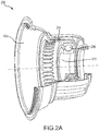
FIG. 2A illustrates a perspective view of a cutaway portion of an exemplary bearing housing, in accordance with various embodiments; -
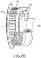
FIG. 2B illustrates a perspective view of a cutaway portion of a bearing and squirrel cage, in accordance with various embodiments; -
FIG. 2C illustrates a cross sectional view of an exemplary bearing housing, in accordance with various embodiments; -
FIG. 3A illustrates a perspective view of a squirrel cage and housing having textured cartridges to form a damper, in accordance with various embodiments; -
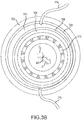
FIG. 3B illustrates a cross sectional view of a bearing housing looking forward to aft with the bearing housing having an inner damper and outer damper, in accordance with various embodiments; -
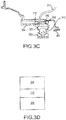
FIG. 3C illustrates a radial cross sectional view of a bearing housing, in accordance with various embodiments; -
FIG. 3D illustrates an inner cartridge and an outer cartridge with a viscous oil layer between the cartridges, in accordance with various embodiments; -
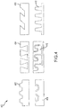
FIG. 4 illustrates exemplary surface configurations for dampers in a bearing housing, in accordance with various embodiments; -
FIG. 5A illustrates a cross sectional view of a bearing housing looking forward to aft with the bearing housing having an inner damper, an outer damper, and an intermediate damper, in accordance with various embodiments; -
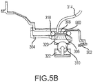
FIG. 5B illustrates a radial cross sectional view of a bearing housing having an inner damper, an outer damper, and an intermediate damper, in accordance with various embodiments; -
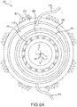
FIG. 6A illustrates a cross sectional view of a bearing housing looking forward to aft with the bearing housing having an inner damper, an outer damper, and cooling fins, in accordance with various embodiments; and -
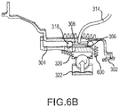
FIG. 6B illustrates a radial cross sectional view of a bearing housing having an inner damper, an outer damper, and cooling fins, in accordance with various embodiments. - The detailed description of exemplary embodiments herein makes reference to the accompanying drawings, which show exemplary embodiments by way of illustration and their best mode. While these exemplary embodiments are described in sufficient detail to enable those skilled in the art to practice the disclosures, it should be understood that other embodiments may be realized and that logical, chemical, and mechanical changes may be made without departing from the scope of the disclosures. Thus, the detailed description herein is presented for purposes of illustration only and not of limitation. For example, the steps recited in any of the method or process descriptions may be executed in any order and are not necessarily limited to the order presented. Furthermore, any reference to singular includes plural embodiments, and any reference to more than one component or step may include a singular embodiment or step. Also, any reference to attached, fixed, connected or the like may include permanent, removable, temporary, partial, full and/or any other possible attachment option. Additionally, any reference to without contact (or similar phrases) may also include reduced contact or minimal contact.
- As used herein, "aft" refers to the direction associated with the tail (e.g., the back end) of an aircraft, or generally, to the direction of exhaust of the gas turbine. As used herein, "forward" refers to the direction associated with the nose (e.g., the front end) of an aircraft, or generally, to the direction of flight or motion.
- Referring to
FIG. 1 , a gas turbine engine 100 (such as a turbofan gas turbine engine) is illustrated according to various embodiments.Gas turbine engine 100 is disposed aboutengine centerline 120, which may also be referred to as axis ofrotation 120.Gas turbine engine 100 may comprise afan 140,compressor sections combustion section 180 including a combustor, andturbine sections compressor sections combustion section 180 and expanded across theturbine sections turbine sections high pressure rotors 192 andlow pressure rotors 194, which rotate in response to the expansion. Theturbine sections blades 196 and static airfoils orvanes 198. Cooling air may be supplied to the combustor andturbine sections compressor sections bearings 115 may support spools in thegas turbine engine 100.FIG. 1 provides a general understanding of the sections in a gas turbine engine, and is not intended to limit the disclosure. The present disclosure may extend to all types of rotating machinery, turbomachinery, and pumps, including turbofan gas turbine engines and turbojet engines, for all types of applications. This may also extend when used in combination with other bearing types in said applications including journal type bearings. - The forward-aft positions of
gas turbine engine 100 lie along axis ofrotation 120. For example,fan 140 may be referred to as forward ofturbine section 190 andturbine section 190 may be referred to as aft offan 140. Typically, during operation ofgas turbine engine 100, air flows from forward to aft, for example, fromfan 140 toturbine section 190. As air flows fromfan 140 to the more aft components ofgas turbine engine 100, axis ofrotation 120 may also generally define the direction of the air stream flow. - Referring to
FIGs. 2A-2C , bearingassembly 200 is shown, in accordance with various embodiments.Bearing assembly 200 may includehousing 202 having an annular or frustoconical geometry.Squirrel cage 204 may be disposed radially inward fromhousing 202.Squirrel cage 204 may retain bearing 206 withouter race 208 contactingsquirrel cage 204.Inner race 210 may be configured to rotate relative toouter race 208. In that regard,inner race 210 may rotate aboutaxis 220 withouter race 208 exhibiting little or no angular displacement.Squirrel cage 204 and/orouter race 208 may define an inner boundary ofcavity 212.Housing 202 may define an outer boundary ofcavity 212. - In various embodiments,
squirrel cage 204 and/or bearing 206 may experience deflection D in response to rotation.Cavity 212 may contain viscous fluid such as oil to provide damping. The viscosity and fluid characteristics of the fluid retained incavity 212 may affect damping performance. Damping may be improved by selectively creating laminar and/or turbulent flow of the viscous fluid incavity 212. - With reference to
FIGs. 3A to 3D , a bearingassembly 300 similar to bearingassembly 200 ofFIG. 2 is shown, in accordance with various embodiments.Bearing assembly 300 may include aninner damper 306 mechanically coupled tosquirrel cage 304.Inner damper 306 may be, for example, press fit or fastened tosquirrel cage 304.Bearing assembly 300 may also include anouter damper 308 mechanically coupled tohousing 302.Inner damper 306 andouter damper 308 may have annular geometries withinner damper 306 having a smaller diameter thanouter damper 308.Outer damper 308 may thus be disposed radially outward frominner damper 306 to definecavity 312 betweenouter damper 308 andinner damper 306. - In various embodiments,
cavity 312 may contain viscous fluid such as oil to provide damping. The oil may be at least partially retained incavity 312 byinner damper 306 andouter damper 308. Oil retained incavity 312 may flow and interact with a textured surface ofinner damper 306 and/orouter damper 308. The surfaces ofinner damper 306 andouter damper 308 may thus impact oil flow and characteristics. The textured surfaces ofinner damper 306 andouter damper 308 may include, for example, intermittent dimpling to disrupt harmonics, features to delay laminar-to-turbulent transitions, and/or features to inhibit oil film cavitation. The texture geometries ofinner damper 306 and/orouter damper 308 may include, for example, dimples, shaped holes, random bumps, tubular dissipation passages, porosity, oil input passages, varying gap width, and/or other suitable configurations. - In various embodiments,
oil input tube 314 may deliver oil intocavity 312. Oil may pass through one or more openings inouter damper 308 intocavity 312.Oil input tube 314 may be in fluid communication with a plurality of oil input passages at least partially defined byouter damper 308. Oil may also pass through one or more openings inouter damper 308 and throughoil output tube 316. In that regard, oil may be added and/or removed tocavity 312 or otherwise circulated. - In various embodiments, engine centerline CL may be the centerline of a gas turbine engine. Axis of rotation AR may be the axis of rotation of
bearing 310. The axis of rotation of bearing 310 may deflect relative the engine centerline CL in response to the rotation of at least one ofinner race 322 orouter race 320 ofbearing 310. The damper system includinginner damper 306 and/orouter damper 308 may dampen the deflection in response to the rotation of bearing 310 at least partially by improving the fluid characteristics of a viscous fluid incavity 312. -
Inner damper 306 and/orouter damper 308 may be formed using additive manufacturing techniques. Additive manufacturing techniques may include direct metal laser sintering, selective laser sintering, selective laser melting, electron-beam melting, or electron-beam freeform fabrication. Additive manufacturing techniques may enable the formation of complex contours oninner damper 306 andouter damper 308. - In various embodiments, and referring to
FIG. 4 , surface textures forinner damper 306 and/orouter damper 308 are shown, in accordance with various embodiments. The textured surface ofinner damper 306 and/orouter damper 308 may be an irregularlytextured surface 402 where the texture includes depressions and protrusions that vary in shape, depth, width, and/or spacing. Thetextured surface 404 ofinner damper 306 and/orouter damper 308 may also include tapered triangular recesses having a narrow opening and broad base.Textured surface 404 may be formed as grooves, trenches, circular dimples, squared dimples, or other suitable shaped dimples. - In various embodiments, the
textured surface 406 ofinner damper 306 and/orouter damper 308 may include angled dimples that enter the surface of the dampers at an angle that is less than or more than 90 degrees. The angled dimples oftextured surface 406 may be extended as grooves or trenches, or the angled dimples may be cylindrical or otherwise shaped. Thetextured surface 408 ofinner damper 306 and/orouter damper 308 may also include oil passages. Oil passages may be configured to remove oil fromcavity 312 ofFIG. 3 and deliver oil back tocavity 312. - In various embodiments, the
textured surface 410 ofinner damper 306 and/orouter damper 308 may include oil passages comprising oil input passages and/or oil output passages to deliver oil to and/or extract oil fromcavity 312. Thetextured surface 412 ofinner damper 306 and/orouter damper 308 may also include dimples having regular shape and protruding from the damper. The geometries ofFIG. 4 are provided as exemplary textured surfaces ofinner damper 306 and/orouter damper 308, and other textured surfaces having varying geometries may also be suitable to limit vibration resulting from rotating machinery. - With reference to
FIGs. 5A to 5B , a bearingassembly 300 having anintermediate damper 500 is shown, in accordance with various embodiments.Intermediate damper 500 may have similar properties asinner damper 306 and/orouter damper 308. Intermediate damper may have an annular shape and be disposed betweeninner damper 306 andouter damper 308 incavity 312. Intermediate damper may float freely withincavity 312 and have one or more textured surfaces to improve flow characteristics of viscous fluid and thereby improve damping. The deflection of bearing 310 and/orsquirrel cage 304 may pressinner damper 306 towardsintermediate damper 500 in response to deflection D. Theintermediate damper 500 may thus deflect in response to the rotation ofbearing 310. - With reference to
FIGs 6A to 6B , a bearingassembly 300 havingcooling fins 600 is shown, in accordance with various embodiments. Coolingfins 600 may be coupled to bearingassembly 300 to provide conductive and convective cooling tocavity 312. Cooling fins may be coupled tohousing 302,squirrel cage 304, or other suitable components in bearingassembly 300. The cooling fins may cool viscous fluid retained incavity 312 by dissipating heat conducted from the viscous fluid, through components of the bearing assembly such asinner damper 306,outer damper 308, orsquirrel cage 304. By reducing the heat of the viscous fluid, the viscosity of the viscous fluid may tend to increase and thereby improve damping characteristics of the damper system. The cooling fins may be made using additive manufacturing. - Benefits, other advantages, and solutions to problems have been described herein with regard to specific embodiments. Furthermore, the connecting lines shown in the various figures contained herein are intended to represent exemplary functional relationships and/or physical couplings between the various elements. It should be noted that many alternative or additional functional relationships or physical connections may be present in a practical system. However, the benefits, advantages, solutions to problems, and any elements that may cause any benefit, advantage, or solution to occur or become more pronounced are not to be construed as critical, required, or essential features or elements of the disclosures. The scope of the disclosures is accordingly to be limited by nothing other than the appended claims, in which reference to an element in the singular is not intended to mean "one and only one" unless explicitly so stated, but rather "one or more." Moreover, where a phrase similar to "at least one of A, B, or C" is used in the claims, it is intended that the phrase be interpreted to mean that A alone may be present in an embodiment, B alone may be present in an embodiment, C alone may be present in an embodiment, or that any combination of the elements A, B and C may be present in a single embodiment; for example, A and B, A and C, B and C, or A and B and C. Different cross-hatching is used throughout the figures to denote different parts but not necessarily to denote the same or different materials.
- Systems, methods and apparatus are provided herein. In the detailed description herein, references to "one embodiment", "an embodiment", "an example embodiment", etc., indicate that the embodiment described may include a particular feature, structure, or characteristic, but every embodiment may not necessarily include the particular feature, structure, or characteristic. Moreover, such phrases are not necessarily referring to the same embodiment. Further, when a particular feature, structure, or characteristic is described in connection with an embodiment, it is submitted that it is within the knowledge of one skilled in the art to affect such feature, structure, or characteristic in connection with other embodiments whether or not explicitly described. After reading the description, it will be apparent to one skilled in the relevant art(s) how to implement the disclosure in alternative embodiments.
- As used herein, the terms "comprises", "comprising", or any other variation thereof, are intended to cover a non-exclusive inclusion, such that a process, method, article, or apparatus that comprises a list of elements does not include only those elements but may include other elements not expressly listed or inherent to such process, method, article, or apparatus.
Claims (15)
- A damper system, comprising:an inner damper (306) having a first annular geometry and a first textured surface (402, 404,406,408,410,412);an outer damper (308) comprising a second annular geometry disposed about the inner damper (306), the outer damper (308) having a second textured surface (402 ... 412); anda cavity (312) at least partially defined by the first textured surface (402 ... 412) and the second textured surface (402 ... 412), wherein the cavity (312) is configured to contain a viscous fluid.
- The damper system of claim 1, wherein at least one of the inner damper (306) or the outer damper (308) comprises steel.
- The damper system of claim 1 or 2, further comprising a seal configured to retain the viscous fluid within the cavity (312).
- The damper system claim 1, 2 or 3, further comprising a cooling fin (600) is configured to cool the viscous fluid, wherein, optionally, the cooling fin (600) is made using additive manufacturing.
- The damper system of any preceding claim, wherein at least one of the first textured surface (402 ... 412) or the second textured surface (402 ... 412) are made using additive manufacturing.
- The damper system of any preceding claim, wherein the inner damper (306) is configured for mechanical coupling to a bearing (115; 206; 310), and wherein, optionally, the outer damper (308) is configured for mechanical coupling to a housing (202; 302).
- The damper system of any preceding claim, wherein at least one of the inner damper (306) or the outer damper (308) comprise a plurality of oil passages.
- The damper system of any preceding claim, wherein at least one of the inner damper (306) or the outer damper (308) define a plurality of dimples.
- The damper system of any preceding claim, further comprising an intermediate damper (500) having an annular geometry and disposed between the outer damper (308) and the inner damper (306).
- A bearing assembly (300), comprising:a bearing (115; 206; 310) having an annular geometry and configured to rotate about an axis (220; AR);a first damper (306) disposed about the bearing (115; 306; 310) with the first damper (306) comprising a textured surface (402 ... 412) configured to contact a viscous fluid; anda housing (202; 302) disposed about the first damper (306), wherein the first damper (306) is configured to dampen a deflection.
- The bearing assembly of claim 10, further comprising:a second damper (308) disposed about the first damper (306), wherein the first damper (306) and the second damper (308) at least partially define a cavity (312) configured to contain the viscous fluid; and, optionallya third damper disposed between the first damper (306) and the second damper (308).
- The bearing assembly of claim 10 or 11, wherein the textured surface (402 ... 412) of the first damper (306) at least one of comprises a plurality of oil passages, defines a plurality of dimples, and/or is made using additive manufacturing.
- The bearing assembly of claim 10, 11 or 12, wherein the first damper (306) is configured to dampen the deflection of the bearing (115; 206; 310) in response to a rotation about the axis (220; AR) of at least one of an inner race (210; 322) of the bearing (115; 206; 310) or an outer race (208; 320) of the bearing (115; 206; 310).
- A gas turbine engine (100), comprising:a bearing (115; 206; 310) having an axis of rotation (220; AR), wherein the axis of rotation (220; AR) of the bearing (115; 206; 310) is configured to deflect in response to a rotation of the bearing (115; 206; 310);a housing (202; 320) disposed about the bearing (115; 206; 310); anda damper (306, 308) disposed about the bearing (115; 206; 310), the damper (306, 308) at least partially defining a cavity (312).
- The gas turbine engine of claim 14, wherein the damper (306, 308) comprises a textured surface (402 ... 412) configured to dampen deflection, wherein the textured surface (402 ... 412) is made using additive manufacturing.
Applications Claiming Priority (1)
| Application Number | Priority Date | Filing Date | Title |
|---|---|---|---|
| US15/053,803 US9879750B2 (en) | 2016-02-25 | 2016-02-25 | Systems and methods for oil damping with textured damper surfaces |
Publications (2)
| Publication Number | Publication Date |
|---|---|
| EP3228886A1 true EP3228886A1 (en) | 2017-10-11 |
| EP3228886B1 EP3228886B1 (en) | 2020-12-16 |
Family
ID=58185353
Family Applications (1)
| Application Number | Title | Priority Date | Filing Date |
|---|---|---|---|
| EP17157980.8A Active EP3228886B1 (en) | 2016-02-25 | 2017-02-24 | Bearing assembly with a squeeze film damper for a gas turbine engine having textured damper surfaces |
Country Status (2)
| Country | Link |
|---|---|
| US (1) | US9879750B2 (en) |
| EP (1) | EP3228886B1 (en) |
Cited By (2)
| Publication number | Priority date | Publication date | Assignee | Title |
|---|---|---|---|---|
| EP3783204A1 (en) * | 2019-08-23 | 2021-02-24 | Raytheon Technologies Corporation | Squeeze film damper acoustic isolation and corresponding method |
| DE102022132002A1 (en) | 2021-12-03 | 2023-06-07 | Avl List Gmbh | DYNAMIC TEST BENCH FOR DUT |
Families Citing this family (21)
| Publication number | Priority date | Publication date | Assignee | Title |
|---|---|---|---|---|
| US10352193B2 (en) * | 2017-08-16 | 2019-07-16 | United Technologies Corporation | Bearing centering spring and damper |
| US10837485B2 (en) * | 2018-05-07 | 2020-11-17 | Ford Global Technologies, Llc | Methods and systems for a crankshaft stabilizing device |
| US10677087B2 (en) | 2018-05-11 | 2020-06-09 | General Electric Company | Support structure for geared turbomachine |
| CN108402995A (en) * | 2018-05-14 | 2018-08-17 | 珠海格力电器股份有限公司 | Device with liquid bag noise reduction and shock absorption structure and dust collector with device |
| US10801366B2 (en) | 2018-05-15 | 2020-10-13 | General Electric Company | Variable stiffness bearing housing |
| US10823002B2 (en) | 2018-05-15 | 2020-11-03 | General Electric Company | Variable stiffness static structure |
| US10823003B2 (en) | 2018-05-25 | 2020-11-03 | General Electric Company | System and method for mitigating undesired vibrations at a turbo machine |
| US11493407B2 (en) | 2018-09-28 | 2022-11-08 | Ge Avio S.R.L. | Torque measurement system |
| US10641325B1 (en) | 2018-10-12 | 2020-05-05 | Pratt & Whitney Canada Corp. | Damping device for a bearing housing |
| US11097835B2 (en) * | 2019-01-30 | 2021-08-24 | Goodrich Corporation | Additively manufactured thermoplastic metering pin with slots for retention hardware |
| US10954817B2 (en) | 2019-07-26 | 2021-03-23 | Pratt & Whitney Canada Corp. | Method of separating and sealing multi film damper rings |
| US10947863B2 (en) | 2019-07-26 | 2021-03-16 | Pratt & Whitney Canada Corp. | Method to supply oil to a multi-film damper |
| US10883383B1 (en) | 2019-07-26 | 2021-01-05 | Pratt & Whitney Canada Corp. | Multi-film damper rings with spacers |
| US11021998B2 (en) | 2019-08-08 | 2021-06-01 | General Electric Company | Shape memory alloy sleeve support assembly for a bearing |
| FR3107550B1 (en) * | 2020-02-24 | 2022-01-28 | Safran Aircraft Engines | METHOD FOR ASSEMBLING AN AIRCRAFT TURBOMACHINE MODULE |
| US11674397B2 (en) * | 2020-11-18 | 2023-06-13 | General Electric Company | Variable stiffness damper system |
| US11828235B2 (en) | 2020-12-08 | 2023-11-28 | General Electric Company | Gearbox for a gas turbine engine utilizing shape memory alloy dampers |
| US11441605B1 (en) | 2021-03-01 | 2022-09-13 | Pratt & Whitney Canada Corp. | Dual-film damper |
| US12546234B2 (en) * | 2022-11-07 | 2026-02-10 | Rtx Corporation | Bearing chamber with thermal heat exchange fins |
| US20240151155A1 (en) * | 2022-11-07 | 2024-05-09 | Rtx Corporation | Bearing chamber with mapped thermal heat exchange fins |
| US20250237158A1 (en) * | 2024-01-23 | 2025-07-24 | Pratt & Whitney Canada Corp. | Aircraft ball bearing squirrel cage with beams with enlarged ends |
Citations (10)
| Publication number | Priority date | Publication date | Assignee | Title |
|---|---|---|---|---|
| DE952756C (en) * | 1953-02-24 | 1956-11-22 | Maschf Augsburg Nuernberg Ag | Exhaust gas turbo unit with flexible bearing of the rotor shaft |
| US3364771A (en) * | 1965-10-27 | 1968-01-23 | Takahashi Takashi | Gear transmission mechanism |
| GB1284602A (en) * | 1969-05-10 | 1972-08-09 | Rolls Royce | Improvements in bearing assemblies |
| US4527912A (en) * | 1984-05-31 | 1985-07-09 | General Motors Corporation | Squeeze film damper |
| US5211489A (en) * | 1992-10-07 | 1993-05-18 | The United States Of America As Represented By The Administrator Of The National Aeronautics And Space Administration | Radial spline assembly for antifriction bearings |
| JPH06109018A (en) * | 1992-09-29 | 1994-04-19 | Mitsubishi Heavy Ind Ltd | Squeezed film damper |
| JP2000002257A (en) * | 1998-06-17 | 2000-01-07 | Nippon Seiko Kk | Rolling bearing |
| US6196721B1 (en) * | 1998-09-11 | 2001-03-06 | Stephen J. Farkaly | Sinusoidal viscous interface for attenuation of vibration for ball and roller bearings |
| US20060204153A1 (en) * | 2005-03-10 | 2006-09-14 | Honeywell International Inc. | Compact resilient anisotropic support for bearing |
| WO2015088634A1 (en) * | 2013-12-13 | 2015-06-18 | United Technologies Corporation | Bearing outer race oil supply for thin film fluidic damping |
Family Cites Families (6)
| Publication number | Priority date | Publication date | Assignee | Title |
|---|---|---|---|---|
| US4545586A (en) * | 1983-04-28 | 1985-10-08 | The United States Of America As Represented By The Administrator Of The National Aeronautics And Space Administration | Damping seal for turbomachinery |
| US5110257A (en) * | 1988-05-12 | 1992-05-05 | United Technologies Corporation | Apparatus for supporting a rotating shaft in a rotary machine |
| US5228784A (en) * | 1991-05-16 | 1993-07-20 | General Electric Company | Squeeze film damper composite ring seal |
| DE4317062C2 (en) * | 1993-05-21 | 1995-08-17 | Freudenberg Carl Fa | Cardan shaft bearing |
| US20110064340A1 (en) * | 2009-09-17 | 2011-03-17 | Loc Quang Duong | Method and apparatus for stabilizing a squeeze film damper for a rotating machine |
| US9470263B2 (en) * | 2015-02-19 | 2016-10-18 | United Technologies Corporation | Squeeze film damper |
-
2016
- 2016-02-25 US US15/053,803 patent/US9879750B2/en active Active
-
2017
- 2017-02-24 EP EP17157980.8A patent/EP3228886B1/en active Active
Patent Citations (10)
| Publication number | Priority date | Publication date | Assignee | Title |
|---|---|---|---|---|
| DE952756C (en) * | 1953-02-24 | 1956-11-22 | Maschf Augsburg Nuernberg Ag | Exhaust gas turbo unit with flexible bearing of the rotor shaft |
| US3364771A (en) * | 1965-10-27 | 1968-01-23 | Takahashi Takashi | Gear transmission mechanism |
| GB1284602A (en) * | 1969-05-10 | 1972-08-09 | Rolls Royce | Improvements in bearing assemblies |
| US4527912A (en) * | 1984-05-31 | 1985-07-09 | General Motors Corporation | Squeeze film damper |
| JPH06109018A (en) * | 1992-09-29 | 1994-04-19 | Mitsubishi Heavy Ind Ltd | Squeezed film damper |
| US5211489A (en) * | 1992-10-07 | 1993-05-18 | The United States Of America As Represented By The Administrator Of The National Aeronautics And Space Administration | Radial spline assembly for antifriction bearings |
| JP2000002257A (en) * | 1998-06-17 | 2000-01-07 | Nippon Seiko Kk | Rolling bearing |
| US6196721B1 (en) * | 1998-09-11 | 2001-03-06 | Stephen J. Farkaly | Sinusoidal viscous interface for attenuation of vibration for ball and roller bearings |
| US20060204153A1 (en) * | 2005-03-10 | 2006-09-14 | Honeywell International Inc. | Compact resilient anisotropic support for bearing |
| WO2015088634A1 (en) * | 2013-12-13 | 2015-06-18 | United Technologies Corporation | Bearing outer race oil supply for thin film fluidic damping |
Cited By (3)
| Publication number | Priority date | Publication date | Assignee | Title |
|---|---|---|---|---|
| EP3783204A1 (en) * | 2019-08-23 | 2021-02-24 | Raytheon Technologies Corporation | Squeeze film damper acoustic isolation and corresponding method |
| US11433322B2 (en) | 2019-08-23 | 2022-09-06 | Raytheon Technologies Corporation | Squeeze film damper acoustic isolation |
| DE102022132002A1 (en) | 2021-12-03 | 2023-06-07 | Avl List Gmbh | DYNAMIC TEST BENCH FOR DUT |
Also Published As
| Publication number | Publication date |
|---|---|
| US9879750B2 (en) | 2018-01-30 |
| US20170248191A1 (en) | 2017-08-31 |
| EP3228886B1 (en) | 2020-12-16 |
Similar Documents
| Publication | Publication Date | Title |
|---|---|---|
| EP3228886B1 (en) | Bearing assembly with a squeeze film damper for a gas turbine engine having textured damper surfaces | |
| US11187102B2 (en) | Method and system for mitigating bowed rotor operation of gas turbine engine | |
| US10036279B2 (en) | Thrust bearing | |
| EP3252280B1 (en) | Circumferential plenum for oil damper | |
| US9879544B2 (en) | Turbine rotor blades with improved tip portion cooling holes | |
| EP3088685B1 (en) | Thermal management system and method of circulating air in a gas turbine engine | |
| EP2546471A2 (en) | Tip clearance control for turbine blades | |
| EP3059463B1 (en) | Squeeze film damper | |
| JP2008106940A (en) | Hydrodynamic seal with circumferentially varying lift | |
| JP2017150484A (en) | Core differential bearing with centering spring and squeeze film damper | |
| EP2964982B1 (en) | Slotted labyrinth seal | |
| EP3712469B1 (en) | Seal plate lubricant slinger | |
| US10738653B2 (en) | Squeeze film damper assemblies | |
| EP3453912B1 (en) | Self pressurizing squeeze film damper | |
| JP2019518176A (en) | Fluid filled damper for gas bearing assembly | |
| CA2963407A1 (en) | Gas distribution labyrinth for bearing pad | |
| US20160003085A1 (en) | Turbine engine adaptive low leakage air seal | |
| JP2017194056A (en) | bearing | |
| EP2985414A1 (en) | Gas turbine engine rotor with annular cavity | |
| US20160258310A1 (en) | Seal arrangement | |
| US11143046B2 (en) | Seal runner and method | |
| WO2013089913A1 (en) | Film cooled turbine component | |
| US11098609B2 (en) | Rotor blade shroud for a turbomachine, rotor blade, method of making a rotor blade shroud and a rotor blade | |
| JP4576180B2 (en) | Air baffle for rotating cavities of gas turbine engines |
Legal Events
| Date | Code | Title | Description |
|---|---|---|---|
| PUAI | Public reference made under article 153(3) epc to a published international application that has entered the european phase |
Free format text: ORIGINAL CODE: 0009012 |
|
| STAA | Information on the status of an ep patent application or granted ep patent |
Free format text: STATUS: THE APPLICATION HAS BEEN PUBLISHED |
|
| AK | Designated contracting states |
Kind code of ref document: A1 Designated state(s): AL AT BE BG CH CY CZ DE DK EE ES FI FR GB GR HR HU IE IS IT LI LT LU LV MC MK MT NL NO PL PT RO RS SE SI SK SM TR |
|
| AX | Request for extension of the european patent |
Extension state: BA ME |
|
| STAA | Information on the status of an ep patent application or granted ep patent |
Free format text: STATUS: REQUEST FOR EXAMINATION WAS MADE |
|
| 17P | Request for examination filed |
Effective date: 20180410 |
|
| RBV | Designated contracting states (corrected) |
Designated state(s): AL AT BE BG CH CY CZ DE DK EE ES FI FR GB GR HR HU IE IS IT LI LT LU LV MC MK MT NL NO PL PT RO RS SE SI SK SM TR |
|
| GRAP | Despatch of communication of intention to grant a patent |
Free format text: ORIGINAL CODE: EPIDOSNIGR1 |
|
| STAA | Information on the status of an ep patent application or granted ep patent |
Free format text: STATUS: GRANT OF PATENT IS INTENDED |
|
| INTG | Intention to grant announced |
Effective date: 20200720 |
|
| RIN1 | Information on inventor provided before grant (corrected) |
Inventor name: HUSBAND, JASON Inventor name: WANG, JOHN ZHIQIANG |
|
| GRAS | Grant fee paid |
Free format text: ORIGINAL CODE: EPIDOSNIGR3 |
|
| GRAA | (expected) grant |
Free format text: ORIGINAL CODE: 0009210 |
|
| STAA | Information on the status of an ep patent application or granted ep patent |
Free format text: STATUS: THE PATENT HAS BEEN GRANTED |
|
| AK | Designated contracting states |
Kind code of ref document: B1 Designated state(s): AL AT BE BG CH CY CZ DE DK EE ES FI FR GB GR HR HU IE IS IT LI LT LU LV MC MK MT NL NO PL PT RO RS SE SI SK SM TR |
|
| REG | Reference to a national code |
Ref country code: GB Ref legal event code: FG4D |
|
| REG | Reference to a national code |
Ref country code: DE Ref legal event code: R096 Ref document number: 602017029483 Country of ref document: DE |
|
| REG | Reference to a national code |
Ref country code: IE Ref legal event code: FG4D |
|
| REG | Reference to a national code |
Ref country code: AT Ref legal event code: REF Ref document number: 1345867 Country of ref document: AT Kind code of ref document: T Effective date: 20210115 |
|
| RAP2 | Party data changed (patent owner data changed or rights of a patent transferred) |
Owner name: RAYTHEON TECHNOLOGIES CORPORATION |
|
| PG25 | Lapsed in a contracting state [announced via postgrant information from national office to epo] |
Ref country code: RS Free format text: LAPSE BECAUSE OF FAILURE TO SUBMIT A TRANSLATION OF THE DESCRIPTION OR TO PAY THE FEE WITHIN THE PRESCRIBED TIME-LIMIT Effective date: 20201216 Ref country code: NO Free format text: LAPSE BECAUSE OF FAILURE TO SUBMIT A TRANSLATION OF THE DESCRIPTION OR TO PAY THE FEE WITHIN THE PRESCRIBED TIME-LIMIT Effective date: 20210316 Ref country code: FI Free format text: LAPSE BECAUSE OF FAILURE TO SUBMIT A TRANSLATION OF THE DESCRIPTION OR TO PAY THE FEE WITHIN THE PRESCRIBED TIME-LIMIT Effective date: 20201216 Ref country code: GR Free format text: LAPSE BECAUSE OF FAILURE TO SUBMIT A TRANSLATION OF THE DESCRIPTION OR TO PAY THE FEE WITHIN THE PRESCRIBED TIME-LIMIT Effective date: 20210317 |
|
| REG | Reference to a national code |
Ref country code: AT Ref legal event code: MK05 Ref document number: 1345867 Country of ref document: AT Kind code of ref document: T Effective date: 20201216 |
|
| REG | Reference to a national code |
Ref country code: NL Ref legal event code: MP Effective date: 20201216 |
|
| PG25 | Lapsed in a contracting state [announced via postgrant information from national office to epo] |
Ref country code: BG Free format text: LAPSE BECAUSE OF FAILURE TO SUBMIT A TRANSLATION OF THE DESCRIPTION OR TO PAY THE FEE WITHIN THE PRESCRIBED TIME-LIMIT Effective date: 20210316 Ref country code: LV Free format text: LAPSE BECAUSE OF FAILURE TO SUBMIT A TRANSLATION OF THE DESCRIPTION OR TO PAY THE FEE WITHIN THE PRESCRIBED TIME-LIMIT Effective date: 20201216 Ref country code: SE Free format text: LAPSE BECAUSE OF FAILURE TO SUBMIT A TRANSLATION OF THE DESCRIPTION OR TO PAY THE FEE WITHIN THE PRESCRIBED TIME-LIMIT Effective date: 20201216 |
|
| PG25 | Lapsed in a contracting state [announced via postgrant information from national office to epo] |
Ref country code: NL Free format text: LAPSE BECAUSE OF FAILURE TO SUBMIT A TRANSLATION OF THE DESCRIPTION OR TO PAY THE FEE WITHIN THE PRESCRIBED TIME-LIMIT Effective date: 20201216 Ref country code: HR Free format text: LAPSE BECAUSE OF FAILURE TO SUBMIT A TRANSLATION OF THE DESCRIPTION OR TO PAY THE FEE WITHIN THE PRESCRIBED TIME-LIMIT Effective date: 20201216 |
|
| REG | Reference to a national code |
Ref country code: LT Ref legal event code: MG9D |
|
| PG25 | Lapsed in a contracting state [announced via postgrant information from national office to epo] |
Ref country code: SK Free format text: LAPSE BECAUSE OF FAILURE TO SUBMIT A TRANSLATION OF THE DESCRIPTION OR TO PAY THE FEE WITHIN THE PRESCRIBED TIME-LIMIT Effective date: 20201216 Ref country code: RO Free format text: LAPSE BECAUSE OF FAILURE TO SUBMIT A TRANSLATION OF THE DESCRIPTION OR TO PAY THE FEE WITHIN THE PRESCRIBED TIME-LIMIT Effective date: 20201216 Ref country code: PT Free format text: LAPSE BECAUSE OF FAILURE TO SUBMIT A TRANSLATION OF THE DESCRIPTION OR TO PAY THE FEE WITHIN THE PRESCRIBED TIME-LIMIT Effective date: 20210416 Ref country code: EE Free format text: LAPSE BECAUSE OF FAILURE TO SUBMIT A TRANSLATION OF THE DESCRIPTION OR TO PAY THE FEE WITHIN THE PRESCRIBED TIME-LIMIT Effective date: 20201216 Ref country code: CZ Free format text: LAPSE BECAUSE OF FAILURE TO SUBMIT A TRANSLATION OF THE DESCRIPTION OR TO PAY THE FEE WITHIN THE PRESCRIBED TIME-LIMIT Effective date: 20201216 Ref country code: SM Free format text: LAPSE BECAUSE OF FAILURE TO SUBMIT A TRANSLATION OF THE DESCRIPTION OR TO PAY THE FEE WITHIN THE PRESCRIBED TIME-LIMIT Effective date: 20201216 Ref country code: LT Free format text: LAPSE BECAUSE OF FAILURE TO SUBMIT A TRANSLATION OF THE DESCRIPTION OR TO PAY THE FEE WITHIN THE PRESCRIBED TIME-LIMIT Effective date: 20201216 |
|
| PG25 | Lapsed in a contracting state [announced via postgrant information from national office to epo] |
Ref country code: AT Free format text: LAPSE BECAUSE OF FAILURE TO SUBMIT A TRANSLATION OF THE DESCRIPTION OR TO PAY THE FEE WITHIN THE PRESCRIBED TIME-LIMIT Effective date: 20201216 Ref country code: PL Free format text: LAPSE BECAUSE OF FAILURE TO SUBMIT A TRANSLATION OF THE DESCRIPTION OR TO PAY THE FEE WITHIN THE PRESCRIBED TIME-LIMIT Effective date: 20201216 |
|
| REG | Reference to a national code |
Ref country code: DE Ref legal event code: R097 Ref document number: 602017029483 Country of ref document: DE |
|
| PG25 | Lapsed in a contracting state [announced via postgrant information from national office to epo] |
Ref country code: MC Free format text: LAPSE BECAUSE OF FAILURE TO SUBMIT A TRANSLATION OF THE DESCRIPTION OR TO PAY THE FEE WITHIN THE PRESCRIBED TIME-LIMIT Effective date: 20201216 Ref country code: IS Free format text: LAPSE BECAUSE OF FAILURE TO SUBMIT A TRANSLATION OF THE DESCRIPTION OR TO PAY THE FEE WITHIN THE PRESCRIBED TIME-LIMIT Effective date: 20210416 |
|
| PLBE | No opposition filed within time limit |
Free format text: ORIGINAL CODE: 0009261 |
|
| STAA | Information on the status of an ep patent application or granted ep patent |
Free format text: STATUS: NO OPPOSITION FILED WITHIN TIME LIMIT |
|
| REG | Reference to a national code |
Ref country code: BE Ref legal event code: MM Effective date: 20210228 |
|
| PG25 | Lapsed in a contracting state [announced via postgrant information from national office to epo] |
Ref country code: CH Free format text: LAPSE BECAUSE OF NON-PAYMENT OF DUE FEES Effective date: 20210228 Ref country code: AL Free format text: LAPSE BECAUSE OF FAILURE TO SUBMIT A TRANSLATION OF THE DESCRIPTION OR TO PAY THE FEE WITHIN THE PRESCRIBED TIME-LIMIT Effective date: 20201216 Ref country code: LI Free format text: LAPSE BECAUSE OF NON-PAYMENT OF DUE FEES Effective date: 20210228 Ref country code: IT Free format text: LAPSE BECAUSE OF FAILURE TO SUBMIT A TRANSLATION OF THE DESCRIPTION OR TO PAY THE FEE WITHIN THE PRESCRIBED TIME-LIMIT Effective date: 20201216 Ref country code: LU Free format text: LAPSE BECAUSE OF NON-PAYMENT OF DUE FEES Effective date: 20210224 |
|
| 26N | No opposition filed |
Effective date: 20210917 |
|
| PG25 | Lapsed in a contracting state [announced via postgrant information from national office to epo] |
Ref country code: DK Free format text: LAPSE BECAUSE OF FAILURE TO SUBMIT A TRANSLATION OF THE DESCRIPTION OR TO PAY THE FEE WITHIN THE PRESCRIBED TIME-LIMIT Effective date: 20201216 |
|
| PG25 | Lapsed in a contracting state [announced via postgrant information from national office to epo] |
Ref country code: ES Free format text: LAPSE BECAUSE OF FAILURE TO SUBMIT A TRANSLATION OF THE DESCRIPTION OR TO PAY THE FEE WITHIN THE PRESCRIBED TIME-LIMIT Effective date: 20201216 Ref country code: IE Free format text: LAPSE BECAUSE OF NON-PAYMENT OF DUE FEES Effective date: 20210224 |
|
| PG25 | Lapsed in a contracting state [announced via postgrant information from national office to epo] |
Ref country code: SI Free format text: LAPSE BECAUSE OF FAILURE TO SUBMIT A TRANSLATION OF THE DESCRIPTION OR TO PAY THE FEE WITHIN THE PRESCRIBED TIME-LIMIT Effective date: 20201216 |
|
| PG25 | Lapsed in a contracting state [announced via postgrant information from national office to epo] |
Ref country code: IS Free format text: LAPSE BECAUSE OF FAILURE TO SUBMIT A TRANSLATION OF THE DESCRIPTION OR TO PAY THE FEE WITHIN THE PRESCRIBED TIME-LIMIT Effective date: 20210416 |
|
| PG25 | Lapsed in a contracting state [announced via postgrant information from national office to epo] |
Ref country code: BE Free format text: LAPSE BECAUSE OF NON-PAYMENT OF DUE FEES Effective date: 20210228 |
|
| PG25 | Lapsed in a contracting state [announced via postgrant information from national office to epo] |
Ref country code: HU Free format text: LAPSE BECAUSE OF FAILURE TO SUBMIT A TRANSLATION OF THE DESCRIPTION OR TO PAY THE FEE WITHIN THE PRESCRIBED TIME-LIMIT; INVALID AB INITIO Effective date: 20170224 |
|
| P01 | Opt-out of the competence of the unified patent court (upc) registered |
Effective date: 20230520 |
|
| PG25 | Lapsed in a contracting state [announced via postgrant information from national office to epo] |
Ref country code: CY Free format text: LAPSE BECAUSE OF FAILURE TO SUBMIT A TRANSLATION OF THE DESCRIPTION OR TO PAY THE FEE WITHIN THE PRESCRIBED TIME-LIMIT Effective date: 20201216 |
|
| PG25 | Lapsed in a contracting state [announced via postgrant information from national office to epo] |
Ref country code: MK Free format text: LAPSE BECAUSE OF FAILURE TO SUBMIT A TRANSLATION OF THE DESCRIPTION OR TO PAY THE FEE WITHIN THE PRESCRIBED TIME-LIMIT Effective date: 20201216 |
|
| PG25 | Lapsed in a contracting state [announced via postgrant information from national office to epo] |
Ref country code: MT Free format text: LAPSE BECAUSE OF FAILURE TO SUBMIT A TRANSLATION OF THE DESCRIPTION OR TO PAY THE FEE WITHIN THE PRESCRIBED TIME-LIMIT Effective date: 20201216 |
|
| REG | Reference to a national code |
Ref country code: DE Ref legal event code: R081 Ref document number: 602017029483 Country of ref document: DE Owner name: RTX CORPORATION (N.D.GES.D. STAATES DELAWARE),, US Free format text: FORMER OWNER: UNITED TECHNOLOGIES CORPORATION, FARMINGTON, CONN., US |
|
| PG25 | Lapsed in a contracting state [announced via postgrant information from national office to epo] |
Ref country code: TR Free format text: LAPSE BECAUSE OF FAILURE TO SUBMIT A TRANSLATION OF THE DESCRIPTION OR TO PAY THE FEE WITHIN THE PRESCRIBED TIME-LIMIT Effective date: 20201216 |
|
| PGFP | Annual fee paid to national office [announced via postgrant information from national office to epo] |
Ref country code: GB Payment date: 20260121 Year of fee payment: 10 |
|
| PGFP | Annual fee paid to national office [announced via postgrant information from national office to epo] |
Ref country code: DE Payment date: 20260121 Year of fee payment: 10 |
|
| PGFP | Annual fee paid to national office [announced via postgrant information from national office to epo] |
Ref country code: FR Payment date: 20260121 Year of fee payment: 10 |