EP3228885A1 - Enhanced durability drive link for high load misalignment - Google Patents
Enhanced durability drive link for high load misalignment Download PDFInfo
- Publication number
- EP3228885A1 EP3228885A1 EP17155049.4A EP17155049A EP3228885A1 EP 3228885 A1 EP3228885 A1 EP 3228885A1 EP 17155049 A EP17155049 A EP 17155049A EP 3228885 A1 EP3228885 A1 EP 3228885A1
- Authority
- EP
- European Patent Office
- Prior art keywords
- inner ring
- formed inner
- drive link
- spherically formed
- clevis
- Prior art date
- Legal status (The legal status is an assumption and is not a legal conclusion. Google has not performed a legal analysis and makes no representation as to the accuracy of the status listed.)
- Withdrawn
Links
Images


Classifications
-
- F—MECHANICAL ENGINEERING; LIGHTING; HEATING; WEAPONS; BLASTING
- F02—COMBUSTION ENGINES; HOT-GAS OR COMBUSTION-PRODUCT ENGINE PLANTS
- F02K—JET-PROPULSION PLANTS
- F02K1/00—Plants characterised by the form or arrangement of the jet pipe or nozzle; Jet pipes or nozzles peculiar thereto
- F02K1/06—Varying effective area of jet pipe or nozzle
- F02K1/12—Varying effective area of jet pipe or nozzle by means of pivoted flaps
- F02K1/1292—Varying effective area of jet pipe or nozzle by means of pivoted flaps of three series of flaps, the upstream series having its flaps hinged at their upstream ends on a fixed structure, the internal downstream series having its flaps hinged at their upstream ends on the downstream ends of the flaps of the upstream series and at their downstream ends on the downstream ends of the flaps of the external downstream series hinged at their upstream ends on a substantially axially movable structure
-
- F—MECHANICAL ENGINEERING; LIGHTING; HEATING; WEAPONS; BLASTING
- F02—COMBUSTION ENGINES; HOT-GAS OR COMBUSTION-PRODUCT ENGINE PLANTS
- F02K—JET-PROPULSION PLANTS
- F02K1/00—Plants characterised by the form or arrangement of the jet pipe or nozzle; Jet pipes or nozzles peculiar thereto
- F02K1/06—Varying effective area of jet pipe or nozzle
- F02K1/15—Control or regulation
-
- B—PERFORMING OPERATIONS; TRANSPORTING
- B23—MACHINE TOOLS; METAL-WORKING NOT OTHERWISE PROVIDED FOR
- B23P—METAL-WORKING NOT OTHERWISE PROVIDED FOR; COMBINED OPERATIONS; UNIVERSAL MACHINE TOOLS
- B23P15/00—Making specific metal objects by operations not covered by a single other subclass or a group in this subclass
- B23P15/003—Making specific metal objects by operations not covered by a single other subclass or a group in this subclass bearings
-
- B—PERFORMING OPERATIONS; TRANSPORTING
- B64—AIRCRAFT; AVIATION; COSMONAUTICS
- B64C—AEROPLANES; HELICOPTERS
- B64C15/00—Attitude, flight direction, or altitude control by jet reaction
-
- F—MECHANICAL ENGINEERING; LIGHTING; HEATING; WEAPONS; BLASTING
- F16—ENGINEERING ELEMENTS AND UNITS; GENERAL MEASURES FOR PRODUCING AND MAINTAINING EFFECTIVE FUNCTIONING OF MACHINES OR INSTALLATIONS; THERMAL INSULATION IN GENERAL
- F16C—SHAFTS; FLEXIBLE SHAFTS; ELEMENTS OR CRANKSHAFT MECHANISMS; ROTARY BODIES OTHER THAN GEARING ELEMENTS; BEARINGS
- F16C23/00—Bearings for exclusively rotary movement adjustable for aligning or positioning
- F16C23/02—Sliding-contact bearings
- F16C23/04—Sliding-contact bearings self-adjusting
- F16C23/043—Sliding-contact bearings self-adjusting with spherical surfaces, e.g. spherical plain bearings
-
- F—MECHANICAL ENGINEERING; LIGHTING; HEATING; WEAPONS; BLASTING
- F16—ENGINEERING ELEMENTS AND UNITS; GENERAL MEASURES FOR PRODUCING AND MAINTAINING EFFECTIVE FUNCTIONING OF MACHINES OR INSTALLATIONS; THERMAL INSULATION IN GENERAL
- F16C—SHAFTS; FLEXIBLE SHAFTS; ELEMENTS OR CRANKSHAFT MECHANISMS; ROTARY BODIES OTHER THAN GEARING ELEMENTS; BEARINGS
- F16C23/00—Bearings for exclusively rotary movement adjustable for aligning or positioning
- F16C23/02—Sliding-contact bearings
- F16C23/04—Sliding-contact bearings self-adjusting
- F16C23/043—Sliding-contact bearings self-adjusting with spherical surfaces, e.g. spherical plain bearings
- F16C23/045—Sliding-contact bearings self-adjusting with spherical surfaces, e.g. spherical plain bearings for radial load mainly, e.g. radial spherical plain bearings
-
- F—MECHANICAL ENGINEERING; LIGHTING; HEATING; WEAPONS; BLASTING
- F05—INDEXING SCHEMES RELATING TO ENGINES OR PUMPS IN VARIOUS SUBCLASSES OF CLASSES F01-F04
- F05D—INDEXING SCHEME FOR ASPECTS RELATING TO NON-POSITIVE-DISPLACEMENT MACHINES OR ENGINES, GAS-TURBINES OR JET-PROPULSION PLANTS
- F05D2260/00—Function
- F05D2260/40—Transmission of power
-
- F—MECHANICAL ENGINEERING; LIGHTING; HEATING; WEAPONS; BLASTING
- F16—ENGINEERING ELEMENTS AND UNITS; GENERAL MEASURES FOR PRODUCING AND MAINTAINING EFFECTIVE FUNCTIONING OF MACHINES OR INSTALLATIONS; THERMAL INSULATION IN GENERAL
- F16C—SHAFTS; FLEXIBLE SHAFTS; ELEMENTS OR CRANKSHAFT MECHANISMS; ROTARY BODIES OTHER THAN GEARING ELEMENTS; BEARINGS
- F16C2360/00—Engines or pumps
- F16C2360/23—Gas turbine engines
Definitions
- the subject matter disclosed herein relates to drive link assemblies.
- a drive link may be used to provide stability while allowing precision movements to an articulated part, such as an articulated nozzle for a gas turbine jet engine.
- a drive link comprises at least a rod end bearing, which is a mechanical articulating joint.
- a drive link configured for use in high-load applications often includes high misalignment spherical bearings.
- conventional hubs that typically cover the bearing are susceptible to fractures. This type of fracture is often initiated by a bearing pin that bends under high tensile stress. The fracture point is typically within the internal diameter and near the edge of the bearing hub.
- the present disclosure provides a drive link that includes a case having a spherically formed inner ring.
- a clevis is affixed to a surface area of the case, adjacent a parameter of the spherically formed inner ring.
- Spacers are positioned on the case surface adjacent the clevis. The spherical inset portions of the spacers are generally aligned with the spherically formed inner ring.
- a spherical bearing is seated within the spherically formed inner ring, with the spacers lining the perimeter of the spherically formed inner ring.
- a rod is affixed to an outer surface of the spherical bearing.
- the spherically formed inner ring comprises a through-hole centrally positioned in a surface of the case.
- the outer diameter of the spherical bearing may be less than the diameter of the spherically formed inner ring. In various embodiments, an outer diameter of the spherical bearing is less than a diameter of the spherically formed inner ring.
- the spacer may comprise either metal, ceramic, mineral, glass, or plastic. The spacers may reduce a range of motion for the spherical bearing.
- the rod includes a rod second end and the second end is attached to an articulated nozzle for a gas turbine engine. Modifying the size and shape of a spacer may be performed based on a desired range of motion.
- the spacer may further include a spherical inset portion.
- the present disclosure includes a method of manufacturing a drive link including molding a case having a spherically formed inner ring.
- a clevis is affixed to a horizontal surface of the case adjacent a parameter of the spherically formed inner ring.
- a spacer is positioned on the horizontal surface adjacent the clevis, the spherical inset portion aligned with the spherically formed inner ring.
- a spherical bearing is inserted within the spherically formed inner ring and the spacer of the case and a rod is attached to an outer surface of the spherical bearing.
- the present disclosure includes a method for installing a drive link to a nozzle assembly that includes attaching a rod first end of a rod to an actuator and attaching a rod second end of the rod to an outer surface of a spherical bearing.
- a spherical bearing is seated within a spherically formed inner ring, wherein the spherically formed inner ring is positioned within a case and adjacent a clevis.
- a clevis first end is connected to a lug and a clevis second end is connected to a case.
- a spacer is positioned on the case adjacent to the clevis, wherein the spacer includes a spherical inset portion in alignment with the spherically formed inner ring.
- the spherically formed inner ring comprises a vertical through-hole centrally positioned in a surface of the case.
- An outer diameter of the spherical bearing is less than a diameter of the spherically formed inner ring.
- any of the method or process descriptions may be executed in any order and are not necessarily limited to the order presented.
- any reference to singular includes plural embodiments, and any reference to more than one component or step may include a singular embodiment or step.
- any reference to attached, fixed, connected, or the like may include permanent, removable, temporary, partial, full, and/or any other possible attachment option.
- any reference to without contact (or similar phrases) may also include reduced contact or minimal contact.
- FIGS. 1-4 An X-Y-Z coordinate system is shown in FIGS. 1-4 for spatial reference purposes, with the orthogonal X and Y-axes defining a horizontal X-Y plane to which the Z-axis is perpendicular.
- the term "vertically extending” includes exactly vertical (i.e., exactly parallel to the Z-axis) and approximately vertical (i.e., approximately parallel to the Z-axis), while the term “horizontally extending” includes exactly horizontal (i.e., exactly parallel to the X-Y plane) and approximately horizontal (i.e., approximately parallel to the X-Y plane).
- FIG. 1 schematically illustrates an example gas turbine engine 156 that includes a fan 142, a compressor 144, a combustor 146 and a turbine 148.
- Alternative engines might include an augmenter (not shown) among other systems or features.
- the fan 142 drives air along a bypass flow path B while the compressor 144 draws air in along a core flow path C where air is compressed and communicated to a combustor 146.
- air is mixed with fuel and ignited to generate a high-pressure exhaust gas stream that expands through the turbine 148 where energy is extracted and utilized to drive the fan 142 and the compressor 144.
- the exhaust gas stream is expelled from gas turbine engine 156 through nozzle 150.
- nozzle 150 may be articulated, which supports variable jet area for engine control and thrust management.
- a drive link assembly may be used to both provide a sturdy connection with the articulated nozzle 150, which is secure while not being overly rigid.
- a rod end bearing configuration for the drive link assembly may provide one or more desired features.
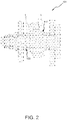
- FIG. 2 illustrates a drive link assembly 101 having a spherical bearing comprising a hub 102 that is integral to the spherical bearing. Removal of the hub 102 from the spherical bearing eliminates the risk that hub 102 will fracture and reduces and/or minimizes the risk that the spherical bearing will fracture. As described herein, a number of spacers, which each comprise a flanged bushing, may replace the functionality of the hub while preserving a desired range of motion for a drive link assembly.
- hub 102 to preserve the misalignment or tilt capability of a drive link assembly 100, the functionality of hub 102 is replaced with spacers 110, 112, 114, 116, allowing hub 102 to be removed and eliminating the risk that hub 102 will fracture, which may be a consequence of deflection or bending of pin 104.
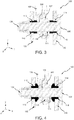
- tilt capability and general range of motion is preserved or enhanced by positioning of spacers 110, 112, 114, 116 along a side portion the case 106 and in alignment with the spherically formed inner ring 107.
- the present disclosure provides a drive link assembly 100 that includes a case 106 having a spherically formed inner ring 107.
- Clevis 130 may be affixed to a surface of case 106 at a clevis first end and a clevis second end, such that the spherically formed inner ring 107 is disposed horizontally between the clevis first end and the clevis second end.
- Spacers 110, 112, 114, 116 may each comprise a spherical inset portion.
- Spacers 110, 112, 114, 116 may be positioned on the surface of case 106 between the clevis first end and the clevis second end and/or between clevis 130 and spherically formed inner ring 107.
- the spherical inset portions of spacers 110, 112, 114, 116 may be generally aligned with spherically formed inner ring 107.
- a spherical bearing 118 is seated within spherically formed inner ring 107, such that spacers 110, 112, 114, 116 line one or more perimeter of spherically formed inner ring 107.
- a rod 108 is affixed to an outer surface of spherical bearing 118.
- a spherical bearing 118 may be centered vertically and/or horizontally relative to a drive link assembly 100 by spacers 110, 112, 114, 116.
- spherical bearing 118 may be secured to drive link assembly 100 by spacers 110, 112, 114, 116.
- spacers 110, 112, 114, 116 may function to preserve spherical bearing 118 misalignment.
- spacers 110, 112, 114, 116 have a spherical inset portion that faces and/or abuts the spherical bearing 118, such that the spherical inset portion is complementary to the contour of spherical bearing 118.
- spacers 110, 112, 114, 116 function to secure spherical bearing 118, maintaining free rotation of spherical bearing 118 about the X-axis while preventing horizontal and/or vertical movement of spherical bearing 118 under various loads.
- replacement of hub 102 with spacers 110, 112, 114, 116 may cause a shear plane to occur nearer a point where the rod 108 attaches to the spherical bearing 118.
- replacement of hub 102 with spacers 110, 112, 114, 116 may reduce deflection of a pin 104 and/or increase even distribution of load.
- FIG. 3 illustrates a drive link assembly having a configuration of spacers 110, 112, 114, 116
- FIG. 4 illustrates a drive link assembly having an alternative arrangement of spacers 110, 112, 114, 116.
- spacers 110, 112, 114, 116 may be presented and described herein, for the purpose of explanation only. Those of ordinary skill in the art will appreciate that many additional configurations may be implemented based on any number of properties. It is also contemplated that properties beyond those described herein, may directly or indirectly influence overall functionality and performance of the drive link assembly 100.
- bearing alignment and retention functions provided by hub are replaced by spacers 110, 112, 114, 116. Some functions are replaced or modified while still others are introduced by way of spacers 110, 112, 114, 116. Such functions include, for example, maintaining or increasing the spherical bearing 118 and/or rod 108 range of motion, while eliminating hub ( FIG. 2 , 102) fracture risks. Modifying the shapes and sizes of spacers 110, 112, 114, 116 may further influence these functions and/or their outcomes.
- secondary considerations may create varied results.
- performance parameters relating to overall stability in an articulated nozzle may change based on spherical bearing 118 manufacturing processes, rather than a size reduction to spacers 110, 112, 114, 116.
- a single configuration of spacers 110, 112, 114, 116 may create varied outcomes based on differences among drive link assembly 100 configurations.
- physical properties of spacers 110, 112, 114, 116 may be specifically defined based on implementation properties. For example, it might be determined that the shape of spacers 110, 112, 114, 116 affect the range of motion for the spherical bearing 118. As such, the shape of spacers 110, 112, 114, 116 may be modified in light of attributes that vary among implementations, such as when a first implementation requires less range of motion than a second implementation.
- spherically formed inner ring 107 comprises a through-hole centrally positioned in a surface of case 106.
- an outer diameter of spherical bearing 118 may be less than the diameter of the spherically formed inner ring 107.
- spacers 110, 112, 114, 116 may comprise metal, ceramic, mineral, glass, plastic, and/or any other suitable material. In various embodiments, spacers 110, 112, 114, 116 reduce a range of motion of spherical bearing 118.
- rod 108 is attached to an articulated nozzle for a gas turbine engine.
- spacers 110, 112, 114, 116 may be performed based on a desired range of motion.
- spacers 110, 112, 114, 116 may further include a spherical inset portion.
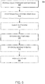
- FIG. 5 a process is described for producing a drive link assembly having the unique features variously described herein.
- a case 106 that is configured to maintain a spherical bearing 118 may be produced through a process of manufacturing 500 that includes shaping liquid or pliable raw material (step 505) to mold/form the case 106.
- a mold for case 106 is filled with metal, ceramic, mineral, glass, or plastic.
- Case 106 includes a spherically formed inner ring 107, which may be cut from or formed into case 106 (step 510), such that the spherically formed inner ring 107 is characterized by an open bore or vertical through-hole.
- Clevis 130 functioning as anchoring points for the drive link assembly 100, is attached (step 515) to a surface portion of the case 106.
- clevis 130 comprises an elongated cylinder that is shaped or molded from a metal, ceramic, mineral, glass, or plastic.
- clevis 130 is affixed to an upper horizontal surface area 109 and/or lower horizontal surface area 111 of case 106, such that clevis 130 extends vertically.
- spacers 110, 112, 114, 116 are positioned (step 520) along upper horizontal surface 109 and/or lower horizontal surface 111 (i.e., parallel to the X-Y plane) of case 106. In various embodiments, spacers 110, 112, 114, 116 are disposed adjacent to clevis 130 and/or between a clevis first end and a clevis second end of clevis 130. In various embodiments, the spacers 110, 112, 114, 116 may comprises a metal, ceramic, mineral, glass, or plastic. The spacers 110, 112, 114, 116 may be formed or molded into various shapes of various sizes.
- spacers 110, 112, 114, 116 are formed to include spherical inset portions. In various embodiments, spacers 110, 112, 114, 116 are positioned such that the inset portions face and/or abut spherical bearing 118 and/or are generally aligned with a spherically formed inner ring 107.
- a spherical bearing 118 is seated (step 525) within the spherically formed inner ring 107 of the case 106 and is disposed horizontally between spacers 110, 112, 114, 116. In various embodiments, the position of spherical bearing 118 is maintained within the spherically formed inner ring 107 by spacers 110, 112, 114, 116.
- a rod 108 is attached (step 530) to spherical bearing 118 to provide movement to, for example, an articulated nozzle of a gas turbine engine.
- FIG. 6 illustrates a process for installing a drive link assembly 100 in accordance with various embodiments.
- the drive link assembly 100 may be installed in a gas turbine engine where it facilitates precise movements of an articulated nozzle.
- a rod first end of a rod 108 that translates motion to the articulated nozzle may be attached to an actuator (step 605), while a rod second end of rod 108 may be attached to spherical bearing 118 of drive link assembly 100 (step 610).
- Spherical bearing 118 is seated within spherically formed inner ring 107 of case 106 (step 615), wherein the spherically formed inner ring 107 is positioned adjacent a clevis 130 (step 620).
- Clevis 130 comprises a clevis first end, which is connected to a lug (step 625) and a clevis second end attached to a horizontal surface 109, 111 of a case 106.
- Spacers 110, 112, 114, 116, including a spherical inset portion may be positioned on horizontal surface 109, 111 of case 106 adjacent clevis 130 and/or between the clevis first end and the clevis second end of clevis 130 (step 630), such that the spherical inset portions are in alignment with spherically formed inner ring 107.
- references to “one embodiment”, “an embodiment”, “various embodiments”, etc. indicate that the embodiment described may include a particular feature, structure, or characteristic, but every embodiment may not necessarily include the particular feature, structure, or characteristic. Moreover, such phrases are not necessarily referring to the same embodiment. Further, when a particular feature, structure, or characteristic is described in connection with an embodiment, it is submitted that it is within the knowledge of one skilled in the art to affect such feature, structure, or characteristic in connection with other embodiments whether or not explicitly described. After reading the description, it will be apparent to one skilled in the relevant art(s) how to implement the disclosure in alternative embodiments.
- the terms “comprises”, “comprising”, or any other variation thereof, are intended to cover a non-exclusive inclusion, such that a process, method, article, or apparatus that comprises a list of elements does not include only those elements but may include other elements not expressly listed or inherent to such process, method, article, or apparatus.
Landscapes
- Engineering & Computer Science (AREA)
- General Engineering & Computer Science (AREA)
- Mechanical Engineering (AREA)
- Chemical & Material Sciences (AREA)
- Combustion & Propulsion (AREA)
- Aviation & Aerospace Engineering (AREA)
- Support Of The Bearing (AREA)
- Pivots And Pivotal Connections (AREA)
Abstract
Description
- The subject matter disclosed herein relates to drive link assemblies.
- A drive link may be used to provide stability while allowing precision movements to an articulated part, such as an articulated nozzle for a gas turbine jet engine. As used herein, a drive link comprises at least a rod end bearing, which is a mechanical articulating joint.
- A drive link configured for use in high-load applications often includes high misalignment spherical bearings. Under very high or abnormal amounts of stress or load, conventional hubs that typically cover the bearing are susceptible to fractures. This type of fracture is often initiated by a bearing pin that bends under high tensile stress. The fracture point is typically within the internal diameter and near the edge of the bearing hub.
- In various embodiments, the present disclosure provides a drive link that includes a case having a spherically formed inner ring. A clevis is affixed to a surface area of the case, adjacent a parameter of the spherically formed inner ring. Spacers, each having a spherical inset portion, are positioned on the case surface adjacent the clevis. The spherical inset portions of the spacers are generally aligned with the spherically formed inner ring. A spherical bearing is seated within the spherically formed inner ring, with the spacers lining the perimeter of the spherically formed inner ring. A rod is affixed to an outer surface of the spherical bearing.
- In various embodiments, the spherically formed inner ring comprises a through-hole centrally positioned in a surface of the case. The outer diameter of the spherical bearing may be less than the diameter of the spherically formed inner ring. In various embodiments, an outer diameter of the spherical bearing is less than a diameter of the spherically formed inner ring. The spacer may comprise either metal, ceramic, mineral, glass, or plastic. The spacers may reduce a range of motion for the spherical bearing. In various embodiments, the rod includes a rod second end and the second end is attached to an articulated nozzle for a gas turbine engine. Modifying the size and shape of a spacer may be performed based on a desired range of motion. The spacer may further include a spherical inset portion.
- In various embodiments, the present disclosure includes a method of manufacturing a drive link including molding a case having a spherically formed inner ring. A clevis is affixed to a horizontal surface of the case adjacent a parameter of the spherically formed inner ring. A spacer is positioned on the horizontal surface adjacent the clevis, the spherical inset portion aligned with the spherically formed inner ring. A spherical bearing is inserted within the spherically formed inner ring and the spacer of the case and a rod is attached to an outer surface of the spherical bearing.
- In various embodiments, the present disclosure includes a method for installing a drive link to a nozzle assembly that includes attaching a rod first end of a rod to an actuator and attaching a rod second end of the rod to an outer surface of a spherical bearing. A spherical bearing is seated within a spherically formed inner ring, wherein the spherically formed inner ring is positioned within a case and adjacent a clevis. A clevis first end is connected to a lug and a clevis second end is connected to a case. A spacer is positioned on the case adjacent to the clevis, wherein the spacer includes a spherical inset portion in alignment with the spherically formed inner ring.
- In various embodiments, the spherically formed inner ring comprises a vertical through-hole centrally positioned in a surface of the case. An outer diameter of the spherical bearing is less than a diameter of the spherically formed inner ring.
- The accompanying drawings are included to provide a further understanding of the present disclosure and are incorporated in, and constitute a part of, this specification, illustrate various embodiments, and together with the description, serve to explain the principles of the disclosure.
-
FIG. 1 is a schematic view of an example gas turbine engine in accordance with various embodiments; -
FIG. 2 illustrates a drive link assembly with a bearing hub; -
FIG. 3 illustrates a drive link assembly with spacers replacing a bearing hub; -
FIG. 4 illustrates a drive link assembly with spacers replacing a bearing hub in accordance with various embodiments; -
FIG. 5 illustrates a process for producing drive link assembly in accordance with various embodiments; and -
FIG. 6 illustrates a process for installing a drive link assembly in accordance with various embodiments. - The detailed description of various embodiments herein makes reference to the accompanying drawings, which show various embodiments by way of illustration. While these various embodiments are described in sufficient detail to enable those skilled in the art to practice the disclosure, it should be understood that other embodiments may be realized and that logical, chemical, and mechanical changes may be made without departing from the scope of the disclosure. Thus, the detailed description herein is presented for purposes of illustration only and not of limitation.
- For example, the steps recited in any of the method or process descriptions may be executed in any order and are not necessarily limited to the order presented. Furthermore, any reference to singular includes plural embodiments, and any reference to more than one component or step may include a singular embodiment or step. Also, any reference to attached, fixed, connected, or the like may include permanent, removable, temporary, partial, full, and/or any other possible attachment option. Additionally, any reference to without contact (or similar phrases) may also include reduced contact or minimal contact.
- An X-Y-Z coordinate system is shown in
FIGS. 1-4 for spatial reference purposes, with the orthogonal X and Y-axes defining a horizontal X-Y plane to which the Z-axis is perpendicular. As used herein, the term "vertically extending" includes exactly vertical (i.e., exactly parallel to the Z-axis) and approximately vertical (i.e., approximately parallel to the Z-axis), while the term "horizontally extending" includes exactly horizontal (i.e., exactly parallel to the X-Y plane) and approximately horizontal (i.e., approximately parallel to the X-Y plane). - As used herein, terms such as "under", "below", "on-top", "above", etc., may be used in describing relative position along the axis, with on top and above reflecting positive Z displacement and under and below reflecting negative Z displacement.
-
FIG. 1 schematically illustrates an examplegas turbine engine 156 that includes afan 142, acompressor 144, acombustor 146 and aturbine 148. Alternative engines might include an augmenter (not shown) among other systems or features. Thefan 142 drives air along a bypass flow path B while thecompressor 144 draws air in along a core flow path C where air is compressed and communicated to acombustor 146. In thecombustor 146, air is mixed with fuel and ignited to generate a high-pressure exhaust gas stream that expands through theturbine 148 where energy is extracted and utilized to drive thefan 142 and thecompressor 144. The exhaust gas stream is expelled fromgas turbine engine 156 throughnozzle 150. - In various embodiments,
nozzle 150 may be articulated, which supports variable jet area for engine control and thrust management. In various embodiments, a drive link assembly may be used to both provide a sturdy connection with the articulatednozzle 150, which is secure while not being overly rigid. In various embodiments, a rod end bearing configuration for the drive link assembly may provide one or more desired features. - Although the disclosed embodiments frequently depict a drive link assembly relative to a gas turbine engine, it should be understood that the drive link assembly described herein is not limited to use with gas turbine engines.
-
FIG. 2 illustrates adrive link assembly 101 having a spherical bearing comprising ahub 102 that is integral to the spherical bearing. Removal of thehub 102 from the spherical bearing eliminates the risk thathub 102 will fracture and reduces and/or minimizes the risk that the spherical bearing will fracture. As described herein, a number of spacers, which each comprise a flanged bushing, may replace the functionality of the hub while preserving a desired range of motion for a drive link assembly. - With brief reference to
FIGs. 2 ,3, and 4 , to preserve the misalignment or tilt capability of adrive link assembly 100, the functionality ofhub 102 is replaced withspacers hub 102 to be removed and eliminating the risk thathub 102 will fracture, which may be a consequence of deflection or bending ofpin 104. Specifically, tilt capability and general range of motion is preserved or enhanced by positioning ofspacers case 106 and in alignment with the spherically formedinner ring 107. - In various embodiments, and with reference to
FIGs. 3 and 4 , the present disclosure provides adrive link assembly 100 that includes acase 106 having a spherically formedinner ring 107.Clevis 130 may be affixed to a surface ofcase 106 at a clevis first end and a clevis second end, such that the spherically formedinner ring 107 is disposed horizontally between the clevis first end and the clevis second end.Spacers Spacers case 106 between the clevis first end and the clevis second end and/or betweenclevis 130 and spherically formedinner ring 107. The spherical inset portions ofspacers inner ring 107. In various embodiments, aspherical bearing 118 is seated within spherically formedinner ring 107, such thatspacers inner ring 107. In various embodiments, arod 108 is affixed to an outer surface ofspherical bearing 118. - Referring to
FIG. 3 and FIG. 4 , in various embodiments, aspherical bearing 118 may be centered vertically and/or horizontally relative to adrive link assembly 100 byspacers spherical bearing 118 may be secured to drivelink assembly 100 byspacers spacers spherical bearing 118 misalignment. In various embodiments,spacers spherical bearing 118, such that the spherical inset portion is complementary to the contour ofspherical bearing 118. - In various embodiments,
spacers spherical bearing 118, maintaining free rotation ofspherical bearing 118 about the X-axis while preventing horizontal and/or vertical movement ofspherical bearing 118 under various loads. In various embodiments, replacement ofhub 102 withspacers rod 108 attaches to thespherical bearing 118. In various embodiments, replacement ofhub 102 withspacers pin 104 and/or increase even distribution of load. -
FIG. 3 illustrates a drive link assembly having a configuration ofspacers FIG. 4 illustrates a drive link assembly having an alternative arrangement ofspacers spacers drive link assembly 100. - In various embodiments, bearing alignment and retention functions provided by hub (
FIG. 2 , 102) are replaced byspacers spacers spherical bearing 118 and/orrod 108 range of motion, while eliminating hub (FIG. 2 , 102) fracture risks. Modifying the shapes and sizes ofspacers - In various embodiments, secondary considerations, not directly relating to variations among
spacers spherical bearing 118 manufacturing processes, rather than a size reduction to spacers 110, 112, 114, 116. Put another way, a single configuration ofspacers drive link assembly 100 configurations. As such, physical properties ofspacers spacers spherical bearing 118. As such, the shape ofspacers - In various embodiments, spherically formed
inner ring 107 comprises a through-hole centrally positioned in a surface ofcase 106. In various embodiments, an outer diameter ofspherical bearing 118 may be less than the diameter of the spherically formedinner ring 107. In various embodiments,spacers spacers spherical bearing 118. In various embodiments,rod 108 is attached to an articulated nozzle for a gas turbine engine. In various embodiments, the size and shape ofspacers spacers - With reference to
FIG. 5 , a process is described for producing a drive link assembly having the unique features variously described herein. Reference is also made to the components illustrated inFIGS. 3 and 4 . It is contemplated that the order of execution for the following process steps may be modified. Moreover, these process steps are presented for explanation only. As such, various steps may be omitted, added, and/or combined without departing from the scope of the disclosure. - A
case 106 that is configured to maintain aspherical bearing 118 may be produced through a process of manufacturing 500 that includes shaping liquid or pliable raw material (step 505) to mold/form thecase 106. In various embodiments, a mold forcase 106 is filled with metal, ceramic, mineral, glass, or plastic.Case 106 includes a spherically formedinner ring 107, which may be cut from or formed into case 106 (step 510), such that the spherically formedinner ring 107 is characterized by an open bore or vertical through-hole. -
Clevis 130, functioning as anchoring points for thedrive link assembly 100, is attached (step 515) to a surface portion of thecase 106. In various embodiments,clevis 130 comprises an elongated cylinder that is shaped or molded from a metal, ceramic, mineral, glass, or plastic. In various embodiments,clevis 130 is affixed to an upperhorizontal surface area 109 and/or lowerhorizontal surface area 111 ofcase 106, such thatclevis 130 extends vertically. - In various embodiments,
spacers horizontal surface 109 and/or lower horizontal surface 111 (i.e., parallel to the X-Y plane) ofcase 106. In various embodiments,spacers clevis 130. In various embodiments, thespacers spacers spacers spacers spherical bearing 118 and/or are generally aligned with a spherically formedinner ring 107. - A
spherical bearing 118 is seated (step 525) within the spherically formedinner ring 107 of thecase 106 and is disposed horizontally betweenspacers spherical bearing 118 is maintained within the spherically formedinner ring 107 byspacers rod 108 is attached (step 530) tospherical bearing 118 to provide movement to, for example, an articulated nozzle of a gas turbine engine. -
FIG. 6 illustrates a process for installing adrive link assembly 100 in accordance with various embodiments. In various embodiments, thedrive link assembly 100 may be installed in a gas turbine engine where it facilitates precise movements of an articulated nozzle. A rod first end of arod 108 that translates motion to the articulated nozzle may be attached to an actuator (step 605), while a rod second end ofrod 108 may be attached tospherical bearing 118 of drive link assembly 100 (step 610).Spherical bearing 118 is seated within spherically formedinner ring 107 of case 106 (step 615), wherein the spherically formedinner ring 107 is positioned adjacent a clevis 130 (step 620).Clevis 130 comprises a clevis first end, which is connected to a lug (step 625) and a clevis second end attached to ahorizontal surface case 106.Spacers horizontal surface case 106adjacent clevis 130 and/or between the clevis first end and the clevis second end of clevis 130 (step 630), such that the spherical inset portions are in alignment with spherically formedinner ring 107. - Benefits, other advantages, and solutions to problems have been described herein with regard to specific embodiments. Furthermore, the connecting lines shown in the various figures contained herein are intended to represent exemplary functional relationships and/or physical couplings between the various elements. It should be noted that many alternative or additional functional relationships or physical connections may be present in a practical system. However, the benefits, advantages, solutions to problems, and any elements that may cause any benefit, advantage, or solution to occur or become more pronounced are not to be construed as critical, required, or essential features or elements of the disclosure. The scope of the disclosure is accordingly to be limited by nothing other than the appended claims, in which reference to an element in the singular is not intended to mean "one and only one" unless explicitly so stated, but rather "one or more." Moreover, where a phrase similar to "at least one of A, B, or C" is used in the claims, it is intended that the phrase be interpreted to mean that A alone may be present in an embodiment, B alone may be present in an embodiment, C alone may be present in an embodiment, or that any combination of the elements A, B and C may be present in a single embodiment; for example, A and B, A and C, B and C, or A and B and C. Different cross-hatching is used throughout the figures to denote different parts but not necessarily to denote the same or different materials.
- Devices and methods are provided herein. In the detailed description herein, references to "one embodiment", "an embodiment", "various embodiments", etc., indicate that the embodiment described may include a particular feature, structure, or characteristic, but every embodiment may not necessarily include the particular feature, structure, or characteristic. Moreover, such phrases are not necessarily referring to the same embodiment. Further, when a particular feature, structure, or characteristic is described in connection with an embodiment, it is submitted that it is within the knowledge of one skilled in the art to affect such feature, structure, or characteristic in connection with other embodiments whether or not explicitly described. After reading the description, it will be apparent to one skilled in the relevant art(s) how to implement the disclosure in alternative embodiments.
- As used herein, the terms "comprises", "comprising", or any other variation thereof, are intended to cover a non-exclusive inclusion, such that a process, method, article, or apparatus that comprises a list of elements does not include only those elements but may include other elements not expressly listed or inherent to such process, method, article, or apparatus.
Claims (14)
- A drive link assembly (100) comprising:a case (106) having a spherically formed inner ring (107);a clevis (130) affixed to a surface of the case (106) such that the spherically formed inner ring (107) is disposed horizontally between a first end and a second end of the clevis (130);a spacer (110,112,114,116) positioned on the surface of the case (106) horizontally between the clevis (130) and the spherically formed inner ring (107), such that a spherical inset portion of the spacer (110,112,114,116) is aligned with the spherically formed inner ring (107);a spherical bearing (118) seated within the spherically formed inner ring (107); anda rod (108) having a rod first end, the rod first end being affixed to an outer surface of the spherical bearing (118).
- A method of manufacturing a drive link comprising
forming a case (106) having a spherically formed inner ring (107);
affixing a clevis (130) to a surface of the case (106) such that the spherically formed inner ring (107) is disposed horizontally between a first end and a second end of the clevis (130);
inserting a spherical bearing (118) within the spherically formed inner ring (107);
positioning a spacer (110,112,114,116) horizontally between the clevis (130) and the spherical bearing (107) such that a spherical inset portion of the spacer (110,112,114,116) is aligned with the spherically formed inner ring (107); and
attaching a rod first end of a rod (108) to an outer surface of the spherical bearing (118). - The drive link assembly of claim 1 or the method of claim 2, wherein the spherically formed inner ring (107) comprises a vertical through-hole centrally positioned in the surface of the case (106).
- The drive link assembly or method of any preceding claim, wherein an outer diameter of the spherical bearing (118) is less than a diameter of the spherically formed inner ring (107).
- The drive link assembly or method of any preceding claim, wherein the spacer (110,112,114,116) comprises at least one of metal, ceramic, mineral, glass, or plastic.
- The drive link assembly or method of any preceding claim, wherein the spacer (110,112,114,116) reduces a range of motion for the spherical bearing (118).
- The drive link assembly or method of any preceding claim, wherein the rod further comprises a rod second end.
- The drive link assembly or method of claim 7, wherein the rod (108) second end is attached to an articulated nozzle for a gas turbine engine.
- The drive link assembly or method of any preceding claim, wherein a size and shape of the spacer (110,112,114,116) is modified based on a desired range of motion.
- The drive link assembly or method of any preceding claim, wherein the spacer includes a/the spherical inset portion.
- The drive link assembly or method of any preceding claim, wherein the spacer reduces stress resulting from a bent pin.
- A method for installing a drive link to a nozzle assembly comprising:attaching a rod first end of a rod (108) to an actuator;attaching a rod second end of the rod (108) to an outer surface of a spherical bearing (118);seating the spherical bearing (118) within a spherically formed inner ring (107), wherein the spherically formed inner ring (107) is disposed on a case (106) horizontally between a first end and a second end of a clevis (130);connecting a first end of the clevis (130) to a lug,connecting a second end of the clevis (130) to the case (106); andpositioning a spacer (110,112,114,116) on the case (106) horizontally between the first end and the second end of the clevis (130), such that a spherical inset portion of the spacer (110,112,114,116) is in alignment with the spherically formed inner ring (107).
- The method of claim 12, wherein the spherically formed inner ring (107) comprises a vertical through-hole centrally positioned in a surface of the case (106).
- The method of claim 12 or 13, wherein an outer diameter of the spherical bearing (118) is less than a diameter of the spherically formed inner ring (107).
Applications Claiming Priority (1)
| Application Number | Priority Date | Filing Date | Title |
|---|---|---|---|
| US15/095,041 US10100779B2 (en) | 2016-04-09 | 2016-04-09 | Enhanced durability drive link for high load misalignment |
Publications (1)
| Publication Number | Publication Date |
|---|---|
| EP3228885A1 true EP3228885A1 (en) | 2017-10-11 |
Family
ID=58185247
Family Applications (1)
| Application Number | Title | Priority Date | Filing Date |
|---|---|---|---|
| EP17155049.4A Withdrawn EP3228885A1 (en) | 2016-04-09 | 2017-02-07 | Enhanced durability drive link for high load misalignment |
Country Status (2)
| Country | Link |
|---|---|
| US (1) | US10100779B2 (en) |
| EP (1) | EP3228885A1 (en) |
Families Citing this family (2)
| Publication number | Priority date | Publication date | Assignee | Title |
|---|---|---|---|---|
| US10634092B2 (en) * | 2017-09-08 | 2020-04-28 | United Technologies Corporation | Linkage assembly preventing axial rotation of the link rod |
| US11066860B1 (en) * | 2020-01-06 | 2021-07-20 | Rohr, Inc. | Hinged assembly with fail-safe hinge pin |
Citations (4)
| Publication number | Priority date | Publication date | Assignee | Title |
|---|---|---|---|---|
| US3464747A (en) * | 1968-03-12 | 1969-09-02 | Roller Bearing Co Of America | Self-aligning plain bearing |
| DE2915088A1 (en) * | 1979-04-12 | 1980-10-16 | Industrieanlagen Betriebsges | Hydraulic bearing assembly with thrust member - includes annular component and contains hydraulic pressure chamber |
| US4943013A (en) * | 1988-09-01 | 1990-07-24 | Societe Nationale D'etude Et De Construction De Moteurs D-Aviation (Snecma) | Fastener system for a jet engine mounting |
| US20150167726A1 (en) * | 2013-12-12 | 2015-06-18 | Airbus Operations (Sas) | Assembly comprising an articulation spindle supported by a clevis and immobilized in translation by a blocking device integrating a double anti-rotation system |
Family Cites Families (16)
| Publication number | Priority date | Publication date | Assignee | Title |
|---|---|---|---|---|
| US2766079A (en) * | 1952-05-09 | 1956-10-09 | William H Browne | Rod end bearing |
| US4243192A (en) * | 1978-12-04 | 1981-01-06 | Mcdonnell Douglas Corporation | Ball pivot thrust bearing flex joint |
| US4385673A (en) * | 1980-09-26 | 1983-05-31 | Caterpillar Tractor Co. | Spherical joint with flexible seals |
| US4808023A (en) * | 1985-02-12 | 1989-02-28 | The United States Of America As Represented By The Secretary Of The Air Force | Dual load path pin clevis joint |
| IT1235963B (en) * | 1989-12-13 | 1992-12-09 | Fiatgeotech | DEVICE FOR THE CONTROL OF THE STRUCTURE OF A TOOL PULLED BY AN AGRICULTURAL MACHINE |
| US5058829A (en) * | 1990-01-12 | 1991-10-22 | Weber Aircraft | Seat track fitting |
| US6371681B1 (en) * | 1999-09-20 | 2002-04-16 | Bell Helicopter Textron Inc. | Anti-rotation clip |
| US6330995B1 (en) * | 2000-02-29 | 2001-12-18 | General Electric Company | Aircraft engine mount |
| FR2907177B1 (en) * | 2006-10-13 | 2009-12-04 | Snecma | ASSEMBLING A ROTULATING DEVICE ON AN ANGLE RETRACTING CAP, A CONTROL SYSTEM FOR A VARIABLE TIMING RECTIFIER COMPRISING IT, AND AN AIRCRAFT ENGINE BEING MUNIED |
| FR2923459B1 (en) * | 2007-11-09 | 2010-05-21 | Snecma | ROTATING BLOCKING MEANS FOR A AXIS SUPPORTING A TURBOMOTEUR SUSPENSION MEMBER |
| US8622644B2 (en) * | 2010-05-28 | 2014-01-07 | Caterpillar Inc. | Seal assembly and method for forming a seal assembly |
| FR2975132B1 (en) * | 2011-05-09 | 2015-06-26 | Snecma | SUSPENSION LINKS OF THE COLD FLOW CHANNEL OF A TURBOJUSTER WITH EXCENTRIC BALLS |
| US20130042630A1 (en) * | 2011-08-19 | 2013-02-21 | United Technologies Corporation | Gas turbine engine accessory mount |
| US8851417B2 (en) * | 2012-08-07 | 2014-10-07 | United Technologies Corporation | Self-retaining shear pin for blind mount location |
| EP2851219B1 (en) * | 2013-09-18 | 2017-06-21 | Alfred Kärcher GmbH & Co. KG | Articulated joint for an implement carrier vehicle and an implement carrier vehicle comprising such articulated joint |
| FR3014970B1 (en) * | 2013-12-12 | 2016-01-22 | Airbus Operations Sas | ASSEMBLY COMPRISING A JOINT AXLE SUPPORTED BY A CAP AND IMMOBILIZED IN TRANSLATION BY A LOCKING DEVICE INCORPORATING A DOUBLE ANTI-ROTATION SYSTEM |
-
2016
- 2016-04-09 US US15/095,041 patent/US10100779B2/en active Active
-
2017
- 2017-02-07 EP EP17155049.4A patent/EP3228885A1/en not_active Withdrawn
Patent Citations (4)
| Publication number | Priority date | Publication date | Assignee | Title |
|---|---|---|---|---|
| US3464747A (en) * | 1968-03-12 | 1969-09-02 | Roller Bearing Co Of America | Self-aligning plain bearing |
| DE2915088A1 (en) * | 1979-04-12 | 1980-10-16 | Industrieanlagen Betriebsges | Hydraulic bearing assembly with thrust member - includes annular component and contains hydraulic pressure chamber |
| US4943013A (en) * | 1988-09-01 | 1990-07-24 | Societe Nationale D'etude Et De Construction De Moteurs D-Aviation (Snecma) | Fastener system for a jet engine mounting |
| US20150167726A1 (en) * | 2013-12-12 | 2015-06-18 | Airbus Operations (Sas) | Assembly comprising an articulation spindle supported by a clevis and immobilized in translation by a blocking device integrating a double anti-rotation system |
Also Published As
| Publication number | Publication date |
|---|---|
| US20170292472A1 (en) | 2017-10-12 |
| US10100779B2 (en) | 2018-10-16 |
Similar Documents
| Publication | Publication Date | Title |
|---|---|---|
| CN108457705B (en) | Method and system for joining ceramic matrix composite material member to metal member | |
| DE602005003891T2 (en) | Shroud segment of a turbine engine and suspension device | |
| US7861535B2 (en) | Self-aligning liner support hanger | |
| US8616847B2 (en) | Abrasive coated preform for a turbine blade tip | |
| US8956487B2 (en) | Rotor blade of a gas turbine engine made of composite material comprising a connecting yoke, method for manufacturing the blade | |
| US6688846B2 (en) | Device for controlling variable-pitch blades | |
| CN110131209B (en) | turbine engine with blades | |
| US20140260281A1 (en) | Auxetic structure with stress-relief features | |
| EP3045685B1 (en) | Mechanical connecting joint and corresponding vane attachment assembly | |
| BR112015027221B1 (en) | AIR INTAKE CHAMBER AND GAS TURBINE ENGINE SYSTEM | |
| US10094393B2 (en) | Mounting systems for gas turbine engines | |
| EP2484870A1 (en) | Blade of a turbomachine with damping element and method of designing a turbomachine | |
| EP3228885A1 (en) | Enhanced durability drive link for high load misalignment | |
| EP2299067B1 (en) | Turbomachine core coupling assembly | |
| JP2007285296A (en) | Method for repairing/replacing vane and turbine engine component | |
| US20190185170A1 (en) | Connection assembly for mounting engine and engine mounting system comprising the same | |
| GB2547108A (en) | A flange joint assembly for use in a gas turbine engine | |
| US20130216368A1 (en) | Turbine stator airfoils with individual orientations | |
| EP3657034A1 (en) | Linkage assembly | |
| EP2230385A1 (en) | Turbine rotor blade | |
| US20170050738A1 (en) | Aft engine mounting link rotational stop collar | |
| US20210122482A1 (en) | Improved fire resistance device designed to be placed between one end of a mounting strut for an aircraft turbomachine and a cowling of said turbomachine delimiting an inter-flow compartment | |
| EP3147459A2 (en) | Nozzle and nozzle assembly for gas turbine engine | |
| EP2559864B1 (en) | Turbomachine load management assembly | |
| EP3336333A1 (en) | Mount structure |
Legal Events
| Date | Code | Title | Description |
|---|---|---|---|
| PUAI | Public reference made under article 153(3) epc to a published international application that has entered the european phase |
Free format text: ORIGINAL CODE: 0009012 |
|
| STAA | Information on the status of an ep patent application or granted ep patent |
Free format text: STATUS: THE APPLICATION HAS BEEN PUBLISHED |
|
| AK | Designated contracting states |
Kind code of ref document: A1 Designated state(s): AL AT BE BG CH CY CZ DE DK EE ES FI FR GB GR HR HU IE IS IT LI LT LU LV MC MK MT NL NO PL PT RO RS SE SI SK SM TR |
|
| AX | Request for extension of the european patent |
Extension state: BA ME |
|
| STAA | Information on the status of an ep patent application or granted ep patent |
Free format text: STATUS: REQUEST FOR EXAMINATION WAS MADE |
|
| 17P | Request for examination filed |
Effective date: 20180411 |
|
| RBV | Designated contracting states (corrected) |
Designated state(s): AL AT BE BG CH CY CZ DE DK EE ES FI FR GB GR HR HU IE IS IT LI LT LU LV MC MK MT NL NO PL PT RO RS SE SI SK SM TR |
|
| STAA | Information on the status of an ep patent application or granted ep patent |
Free format text: STATUS: EXAMINATION IS IN PROGRESS |
|
| 17Q | First examination report despatched |
Effective date: 20190204 |
|
| STAA | Information on the status of an ep patent application or granted ep patent |
Free format text: STATUS: THE APPLICATION HAS BEEN WITHDRAWN |
|
| 18W | Application withdrawn |
Effective date: 20190612 |