EP3228819A1 - Blade comprising cmc layers - Google Patents
Blade comprising cmc layers Download PDFInfo
- Publication number
- EP3228819A1 EP3228819A1 EP16164581.7A EP16164581A EP3228819A1 EP 3228819 A1 EP3228819 A1 EP 3228819A1 EP 16164581 A EP16164581 A EP 16164581A EP 3228819 A1 EP3228819 A1 EP 3228819A1
- Authority
- EP
- European Patent Office
- Prior art keywords
- blade
- diverging walls
- root
- airfoil
- reinforcement element
- Prior art date
- Legal status (The legal status is an assumption and is not a legal conclusion. Google has not performed a legal analysis and makes no representation as to the accuracy of the status listed.)
- Granted
Links
Images


Classifications
-
- F—MECHANICAL ENGINEERING; LIGHTING; HEATING; WEAPONS; BLASTING
- F01—MACHINES OR ENGINES IN GENERAL; ENGINE PLANTS IN GENERAL; STEAM ENGINES
- F01D—NON-POSITIVE DISPLACEMENT MACHINES OR ENGINES, e.g. STEAM TURBINES
- F01D5/00—Blades; Blade-carrying members; Heating, heat-insulating, cooling or antivibration means on the blades or the members
- F01D5/12—Blades
- F01D5/28—Selecting particular materials; Particular measures relating thereto; Measures against erosion or corrosion
-
- F—MECHANICAL ENGINEERING; LIGHTING; HEATING; WEAPONS; BLASTING
- F01—MACHINES OR ENGINES IN GENERAL; ENGINE PLANTS IN GENERAL; STEAM ENGINES
- F01D—NON-POSITIVE DISPLACEMENT MACHINES OR ENGINES, e.g. STEAM TURBINES
- F01D5/00—Blades; Blade-carrying members; Heating, heat-insulating, cooling or antivibration means on the blades or the members
- F01D5/12—Blades
- F01D5/14—Form or construction
- F01D5/18—Hollow blades, i.e. blades with cooling or heating channels or cavities; Heating, heat-insulating or cooling means on blades
- F01D5/187—Convection cooling
- F01D5/188—Convection cooling with an insert in the blade cavity to guide the cooling fluid, e.g. forming a separation wall
-
- F—MECHANICAL ENGINEERING; LIGHTING; HEATING; WEAPONS; BLASTING
- F01—MACHINES OR ENGINES IN GENERAL; ENGINE PLANTS IN GENERAL; STEAM ENGINES
- F01D—NON-POSITIVE DISPLACEMENT MACHINES OR ENGINES, e.g. STEAM TURBINES
- F01D5/00—Blades; Blade-carrying members; Heating, heat-insulating, cooling or antivibration means on the blades or the members
- F01D5/12—Blades
- F01D5/14—Form or construction
- F01D5/18—Hollow blades, i.e. blades with cooling or heating channels or cavities; Heating, heat-insulating or cooling means on blades
-
- F—MECHANICAL ENGINEERING; LIGHTING; HEATING; WEAPONS; BLASTING
- F01—MACHINES OR ENGINES IN GENERAL; ENGINE PLANTS IN GENERAL; STEAM ENGINES
- F01D—NON-POSITIVE DISPLACEMENT MACHINES OR ENGINES, e.g. STEAM TURBINES
- F01D5/00—Blades; Blade-carrying members; Heating, heat-insulating, cooling or antivibration means on the blades or the members
- F01D5/12—Blades
- F01D5/28—Selecting particular materials; Particular measures relating thereto; Measures against erosion or corrosion
- F01D5/282—Selecting composite materials, e.g. blades with reinforcing filaments
-
- F—MECHANICAL ENGINEERING; LIGHTING; HEATING; WEAPONS; BLASTING
- F01—MACHINES OR ENGINES IN GENERAL; ENGINE PLANTS IN GENERAL; STEAM ENGINES
- F01D—NON-POSITIVE DISPLACEMENT MACHINES OR ENGINES, e.g. STEAM TURBINES
- F01D5/00—Blades; Blade-carrying members; Heating, heat-insulating, cooling or antivibration means on the blades or the members
- F01D5/12—Blades
- F01D5/28—Selecting particular materials; Particular measures relating thereto; Measures against erosion or corrosion
- F01D5/284—Selection of ceramic materials
-
- F—MECHANICAL ENGINEERING; LIGHTING; HEATING; WEAPONS; BLASTING
- F01—MACHINES OR ENGINES IN GENERAL; ENGINE PLANTS IN GENERAL; STEAM ENGINES
- F01D—NON-POSITIVE DISPLACEMENT MACHINES OR ENGINES, e.g. STEAM TURBINES
- F01D5/00—Blades; Blade-carrying members; Heating, heat-insulating, cooling or antivibration means on the blades or the members
- F01D5/30—Fixing blades to rotors; Blade roots ; Blade spacers
- F01D5/3084—Fixing blades to rotors; Blade roots ; Blade spacers the blades being made of ceramics
-
- F—MECHANICAL ENGINEERING; LIGHTING; HEATING; WEAPONS; BLASTING
- F01—MACHINES OR ENGINES IN GENERAL; ENGINE PLANTS IN GENERAL; STEAM ENGINES
- F01D—NON-POSITIVE DISPLACEMENT MACHINES OR ENGINES, e.g. STEAM TURBINES
- F01D5/00—Blades; Blade-carrying members; Heating, heat-insulating, cooling or antivibration means on the blades or the members
- F01D5/30—Fixing blades to rotors; Blade roots ; Blade spacers
- F01D5/3092—Protective layers between blade root and rotor disc surfaces, e.g. anti-friction layers
-
- F—MECHANICAL ENGINEERING; LIGHTING; HEATING; WEAPONS; BLASTING
- F01—MACHINES OR ENGINES IN GENERAL; ENGINE PLANTS IN GENERAL; STEAM ENGINES
- F01D—NON-POSITIVE DISPLACEMENT MACHINES OR ENGINES, e.g. STEAM TURBINES
- F01D5/00—Blades; Blade-carrying members; Heating, heat-insulating, cooling or antivibration means on the blades or the members
- F01D5/12—Blades
- F01D5/14—Form or construction
- F01D5/147—Construction, i.e. structural features, e.g. of weight-saving hollow blades
-
- F—MECHANICAL ENGINEERING; LIGHTING; HEATING; WEAPONS; BLASTING
- F01—MACHINES OR ENGINES IN GENERAL; ENGINE PLANTS IN GENERAL; STEAM ENGINES
- F01D—NON-POSITIVE DISPLACEMENT MACHINES OR ENGINES, e.g. STEAM TURBINES
- F01D5/00—Blades; Blade-carrying members; Heating, heat-insulating, cooling or antivibration means on the blades or the members
- F01D5/12—Blades
- F01D5/14—Form or construction
- F01D5/18—Hollow blades, i.e. blades with cooling or heating channels or cavities; Heating, heat-insulating or cooling means on blades
- F01D5/187—Convection cooling
- F01D5/188—Convection cooling with an insert in the blade cavity to guide the cooling fluid, e.g. forming a separation wall
- F01D5/189—Convection cooling with an insert in the blade cavity to guide the cooling fluid, e.g. forming a separation wall the insert having a tubular cross-section, e.g. airfoil shape
-
- F—MECHANICAL ENGINEERING; LIGHTING; HEATING; WEAPONS; BLASTING
- F01—MACHINES OR ENGINES IN GENERAL; ENGINE PLANTS IN GENERAL; STEAM ENGINES
- F01D—NON-POSITIVE DISPLACEMENT MACHINES OR ENGINES, e.g. STEAM TURBINES
- F01D5/00—Blades; Blade-carrying members; Heating, heat-insulating, cooling or antivibration means on the blades or the members
- F01D5/30—Fixing blades to rotors; Blade roots ; Blade spacers
- F01D5/3007—Fixing blades to rotors; Blade roots ; Blade spacers of axial insertion type
-
- F—MECHANICAL ENGINEERING; LIGHTING; HEATING; WEAPONS; BLASTING
- F05—INDEXING SCHEMES RELATING TO ENGINES OR PUMPS IN VARIOUS SUBCLASSES OF CLASSES F01-F04
- F05D—INDEXING SCHEME FOR ASPECTS RELATING TO NON-POSITIVE-DISPLACEMENT MACHINES OR ENGINES, GAS-TURBINES OR JET-PROPULSION PLANTS
- F05D2220/00—Application
- F05D2220/30—Application in turbines
- F05D2220/32—Application in turbines in gas turbines
- F05D2220/321—Application in turbines in gas turbines for a special turbine stage
-
- F—MECHANICAL ENGINEERING; LIGHTING; HEATING; WEAPONS; BLASTING
- F05—INDEXING SCHEMES RELATING TO ENGINES OR PUMPS IN VARIOUS SUBCLASSES OF CLASSES F01-F04
- F05D—INDEXING SCHEME FOR ASPECTS RELATING TO NON-POSITIVE-DISPLACEMENT MACHINES OR ENGINES, GAS-TURBINES OR JET-PROPULSION PLANTS
- F05D2300/00—Materials; Properties thereof
- F05D2300/60—Properties or characteristics given to material by treatment or manufacturing
- F05D2300/603—Composites; e.g. fibre-reinforced
- F05D2300/6033—Ceramic matrix composites [CMC]
Definitions
- the present invention relates to a blade, in particular a blade of a gas turbine engine.
- Gas turbine engines have a turbine where hot gas is expanded to gather mechanical work.
- the turbine has a plurality of stages, each comprising vanes (which do not rotate) and blades (which rotate).
- the blades have to withstand very severe conditions, due for example to the high centrifugal forces and the high temperature of the gas they are immersed in.
- the conditions are particularly severe for long blades, such as the blades of the last stages (e.g. third, fourth or subsequent stages) of the turbine, because of the particularly high centrifugal forces.
- CMC ceramic matrix composite material
- a shell structure is to be understood as a hollow structure having walls made of CMC.
- the airfoil can have a shell structure as well or it can have a solid structure; the airfoil is advantageously made of CMC.
- a problem with these kinds of blades is the connection of the blades to the rotor. In fact, due to the high stress during operation, there is the risk that the hollow structure of the root collapses.
- An aspect of the invention includes providing a blade with a reduced risk that, during operation, the root or portions thereof may collapse.
- FIGS. 1 show a blade 1 comprising an airfoil 2 and a root 3.
- the blade 1 can be manufactured in one piece in ceramic matrix composite material CMC (this is the preferred solution).
- the airfoil 2 has a tip 4 and the root 3 has a free end 5.
- the root 3 has diverging walls 7; e.g. figures 1-9 shows an embodiment of a root with only one couple of diverging walls; figure 10 shows an example of a root with two couples of diverging walls; in different examples the number of couples of diverging walls can anyhow be any.
- the diverging walls 7 are made of a ceramic matrix composite material CMC and a reinforcement element 8 is provided between the diverging walls 7.
- the diverging walls 7 can be made in one layer or preferably in a plurality of layers 9. This is advantageous in particular for diverging walls 7 of large thickness; in addition a plurality of layers 9 for the diverging walls 7 improves load distribution among the layers 9.
- An embodiment with diverging walls 7 having a plurality of layers 9 is e.g. shown in figures 4 and 5 .
- the diverging walls can also be provided with intermediate layers 11, made of a material different from the ceramic matrix composite material and provided between the layers 9 of ceramic matrix composite material; the intermediate layers 11 can be made of the same material as the reinforcement element 8.
- the intermediate layer or layers 11 can extend only substantially in correspondence of the root 3, as shown in figure 6 , or can also extend in correspondence of part or all the airfoil 3, as shown in figure 7 .
- the reinforcement element 8 can be made from metal or other material; use of metal over other materials such as composite materials like CMC is advantageous because manufacturing is easy and the material (metal) can be chosen according to the needs as for strengths, weight, etc.; in addition, since the reinforcement element 8 is only confined at the root or possibly only extends in the airfoil for a limited portion thereof, the centrifugal forces caused by the reinforcement element 8 are limited and within acceptable limits for the blade.
- the attached figures show the reinforcement element 8 with diverging walls 13; the diverging walls 7 of the root 3 rest on the diverging walls 13 of the reinforcement element 8.
- the reinforcement element 8 can be defined only by the diverging walls 13 with a connecting member interposed between them, or it can be defined by a massive element having the diverging walls 13 (this embodiments is shown in the attached figures).
- Figures 8-10 show embodiments of the reinforcement element 8 provided with one or more cooling passages 14.
- a tubular element 15 made of ceramic matrix composite material CMC or metal is preferably provided in the cooling passage 14, with the side surface of the tubular element 15 resting on the side surface of the cooling passage 14 or not.
- the tubular element can at least partially carry the load, in particular the centrifugal load.
- the cooling passage can have any cross section, e.g. round, oval, square, rectangular, triangular, etc.; likewise, the tubular element can have any cross section, e.g. round, oval, square, rectangular, triangular, etc..
- Reference 16 indicates the side surface of the tubular element 15 and the side surface of the cooling passage 14 resting one against the other.
- the cooling passage 14 extends substantially in the direction 17 of the airfoil 2.
- a duct 23 for cooling air circulation can be provided between the rotor 20 and the blade 1.
- a sacrificial layer 18 can be provided on the diverging walls 7; the sacrificial layer 18 can extend over the whole surface of the diverging walls or only a part thereof.
- the sacrificial layer 18 is arrange to be damaged in place of the diverging walls 7 and/or rotor 20 during operation; for example the sacrificial layer 18 can be made of metal being the same or also different from the metal of the reinforcement element 8. Other materials are naturally possible for the sacrificial layer 18.
- a bounding layer 19 can be provided between the diverging walls 7 and the reinforcement element 8, in order to promote reciprocal adhesion.
- the bounding layer can be a glue layer.
- Figure 10 shows an embodiment of the blade 1 having the root 3 with two couples of diverging walls 7.
- figure 10 shows that diverging walls 7 closer to the airfoil 2 have a larger width L1 in cross section than the width L2 of the diverging walls 7 farther from the airfoil 2.
- the blade 1 is preferably a long blade, such as a blade of a downstream stage of a gas turbine, e.g. third, fourth or subsequent stage.
- the blade can thus have a longitudinal length between the root free end 5 and the airfoil tip 4 of at least 0.8 m and preferably 1 m and more preferably 1.15 m. In a preferred embodiment the blade 1 has a longitudinal length between 1.15-1.25 m.
- the blade 1 is connected to the rotor 20.
- the seat of the rotor 20 housing the root 3 advantageously has tapering 21 at its borders, to reduce stress concentration at the blade 1.
- the rotor 20 rotates, causing rotation of the blades as well.
- the centrifugal forces push the blades radially outwards and the diverging portions 7 retain the blades 1; this causes a compression (as indicated by arrows P) of the diverging walls 7 with the risk of collapse.
- the reinforcing element 8 interposed between the diverging walls 7 supports the diverging walls 7 and counteracts the collapse.
Landscapes
- Engineering & Computer Science (AREA)
- Mechanical Engineering (AREA)
- General Engineering & Computer Science (AREA)
- Chemical & Material Sciences (AREA)
- Materials Engineering (AREA)
- Ceramic Engineering (AREA)
- Composite Materials (AREA)
- Turbine Rotor Nozzle Sealing (AREA)
- Structures Of Non-Positive Displacement Pumps (AREA)
Abstract
Description
- The present invention relates to a blade, in particular a blade of a gas turbine engine.
- Gas turbine engines have a turbine where hot gas is expanded to gather mechanical work. Typically the turbine has a plurality of stages, each comprising vanes (which do not rotate) and blades (which rotate).
- The blades have to withstand very severe conditions, due for example to the high centrifugal forces and the high temperature of the gas they are immersed in. The conditions are particularly severe for long blades, such as the blades of the last stages (e.g. third, fourth or subsequent stages) of the turbine, because of the particularly high centrifugal forces.
- In order to provide blades able to withstand severe conditions, blades made of ceramic matrix composite material (CMC) have been proposed. CMC is a composite material having carbon or ceramic fibres and a ceramic matrix.
US 2012/0 195 766 A1 discloses a blade of this kind. - In particular, in the following reference is made to blades whose root has a shell structure; a shell structure is to be understood as a hollow structure having walls made of CMC. The airfoil can have a shell structure as well or it can have a solid structure; the airfoil is advantageously made of CMC.
- A problem with these kinds of blades is the connection of the blades to the rotor. In fact, due to the high stress during operation, there is the risk that the hollow structure of the root collapses.
- An aspect of the invention includes providing a blade with a reduced risk that, during operation, the root or portions thereof may collapse.
- These and further aspects are attained by providing a blade in accordance with the accompanying claims.
- Further characteristics and advantages will be more apparent from the description of a preferred but non-exclusive embodiment of the blade, illustrated by way of non-limiting example in the accompanying drawings, in which:
-
Figure 1 shows a perspective view of a blade; -
Figure 2 shows a cross section of an airfoil of the blade; -
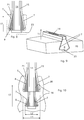
Figures 3 and 4 shows the root of the blade (figure 3 ) and an enlarged portion of the root (figure 4 ); in these figures a portion of the rotor is shown as well; -
Figures 5 through 7 show different embodiments of diverging walls of the root; -
Figures 8 through 10 show a root with a cooling passage. - With reference to the figures, these show a
blade 1 comprising anairfoil 2 and aroot 3. Theblade 1 can be manufactured in one piece in ceramic matrix composite material CMC (this is the preferred solution). - The
airfoil 2 has atip 4 and theroot 3 has afree end 5. - The
root 3 has divergingwalls 7; e.g.figures 1-9 shows an embodiment of a root with only one couple of diverging walls;figure 10 shows an example of a root with two couples of diverging walls; in different examples the number of couples of diverging walls can anyhow be any. - The diverging
walls 7 are made of a ceramic matrix composite material CMC and areinforcement element 8 is provided between the divergingwalls 7. - The diverging
walls 7 can be made in one layer or preferably in a plurality oflayers 9. This is advantageous in particular for divergingwalls 7 of large thickness; in addition a plurality oflayers 9 for the divergingwalls 7 improves load distribution among thelayers 9. An embodiment withdiverging walls 7 having a plurality oflayers 9 is e.g. shown infigures 4 and5 . - The diverging walls can also be provided with
intermediate layers 11, made of a material different from the ceramic matrix composite material and provided between thelayers 9 of ceramic matrix composite material; theintermediate layers 11 can be made of the same material as thereinforcement element 8. - The intermediate layer or
layers 11 can extend only substantially in correspondence of theroot 3, as shown infigure 6 , or can also extend in correspondence of part or all theairfoil 3, as shown infigure 7 . - The
reinforcement element 8 can be made from metal or other material; use of metal over other materials such as composite materials like CMC is advantageous because manufacturing is easy and the material (metal) can be chosen according to the needs as for strengths, weight, etc.; in addition, since thereinforcement element 8 is only confined at the root or possibly only extends in the airfoil for a limited portion thereof, the centrifugal forces caused by thereinforcement element 8 are limited and within acceptable limits for the blade. - The attached figures show the
reinforcement element 8 withdiverging walls 13; thediverging walls 7 of theroot 3 rest on the divergingwalls 13 of thereinforcement element 8. - In different embodiments the
reinforcement element 8 can be defined only by thediverging walls 13 with a connecting member interposed between them, or it can be defined by a massive element having the diverging walls 13 (this embodiments is shown in the attached figures). -
Figures 8-10 show embodiments of thereinforcement element 8 provided with one ormore cooling passages 14. - In this case, a
tubular element 15 made of ceramic matrix composite material CMC or metal is preferably provided in thecooling passage 14, with the side surface of thetubular element 15 resting on the side surface of thecooling passage 14 or not. The tubular element can at least partially carry the load, in particular the centrifugal load. - The cooling passage can have any cross section, e.g. round, oval, square, rectangular, triangular, etc.; likewise, the tubular element can have any cross section, e.g. round, oval, square, rectangular, triangular, etc..
-
Reference 16 indicates the side surface of thetubular element 15 and the side surface of thecooling passage 14 resting one against the other. - The
cooling passage 14 extends substantially in thedirection 17 of theairfoil 2. - In this case a
duct 23 for cooling air circulation can be provided between therotor 20 and theblade 1. - A
sacrificial layer 18 can be provided on thediverging walls 7; thesacrificial layer 18 can extend over the whole surface of the diverging walls or only a part thereof. Thesacrificial layer 18 is arrange to be damaged in place of the divergingwalls 7 and/orrotor 20 during operation; for example thesacrificial layer 18 can be made of metal being the same or also different from the metal of thereinforcement element 8. Other materials are naturally possible for thesacrificial layer 18. - In addition a bounding
layer 19 can be provided between thediverging walls 7 and thereinforcement element 8, in order to promote reciprocal adhesion. For example the bounding layer can be a glue layer. -
Figure 10 shows an embodiment of theblade 1 having theroot 3 with two couples of divergingwalls 7. In particular,figure 10 shows that divergingwalls 7 closer to theairfoil 2 have a larger width L1 in cross section than the width L2 of the divergingwalls 7 farther from theairfoil 2. - The
blade 1 is preferably a long blade, such as a blade of a downstream stage of a gas turbine, e.g. third, fourth or subsequent stage. The blade can thus have a longitudinal length between the rootfree end 5 and theairfoil tip 4 of at least 0.8 m and preferably 1 m and more preferably 1.15 m. In a preferred embodiment theblade 1 has a longitudinal length between 1.15-1.25 m. - During operation, the
blade 1 is connected to therotor 20. The seat of therotor 20 housing theroot 3 advantageously has tapering 21 at its borders, to reduce stress concentration at theblade 1. - During operation the
rotor 20 rotates, causing rotation of the blades as well. The centrifugal forces push the blades radially outwards and the divergingportions 7 retain theblades 1; this causes a compression (as indicated by arrows P) of the divergingwalls 7 with the risk of collapse. The reinforcingelement 8 interposed between the divergingwalls 7 supports thediverging walls 7 and counteracts the collapse. - Naturally the features described may be independently provided from one another. For example, the features of each of the attached claims can be applied independently of the features of the other claims.
- In practice the materials used and the dimensions can be chosen at will according to requirements and to the state of the art.
-
- 1
- blade
- 2
- airfoil
- 3
- root
- 4
- tip
- 5
- free end
- 7
- diverging walls of the
root 3 - 8
- reinforcement element
- 9
- layers
- 11
- intermediate layers
- 13
- diverging walls of the reinforcing
element 8 - 14
- cooling passage
- 15
- tubular element
- 16
- side surfaces
- 17
- direction of the airfoil
- 18
- sacrificial layer
- 19
- bonding layer
- 20
- rotor
- 21
- tapering
- 23
- duct
- L1
- width
- L2
- width
- P
- compression
Claims (14)
- A blade (1) comprising an airfoil (2) and a root (3), the root (3) having diverging walls (7), characterized in that at least the diverging walls (7) are made of a ceramic matrix composite material, and at least a reinforcement element (8) is provided between the diverging walls (7).
- The blade (1) of claim 1, characterized in that the diverging walls (7) are made in a plurality of layers (9).
- The blade (1) of claim 2, characterized in that at least an intermediate layer (11) made of a material different from the ceramic matrix composite material is provided between at least two layers (9) of ceramic matrix composite material.
- The blade (1) of claim 3, characterized in that the at least an intermediate layer (11) extends at least partly in the airfoil (2).
- The blade (1) of claim 1, characterized in that the reinforcement element (8) is a metal element.
- The blade (1) of claim 1 or 5, characterized in that the reinforcement element (8) has reinforcement element diverging walls (13), and in that the diverging walls (7) of the root (3) rest on the reinforcement element diverging walls (13).
- The blade (1) of claim 1, characterized in that the reinforcement element (8) is provided with at least one cooling passage (14).
- The blade (1) of claim 7, characterized by further comprising a tubular element (15) made of ceramic matrix composite material, wherein the tubular element (15) is inserted in the cooling passage (14), and the side surface of the tubular element (15) rests on the side surface of the cooling passage (14).
- The blade (1) of claim 7 or 8, characterized in that the at least one cooling passage (14) extends substantially in the direction (17) of the airfoil.
- The blade (1) of claim 1, characterized by comprising a sacrificial layer (18) on at least a part of the diverging walls (7).
- The blade (1) of claim 1, characterized in that the root (3) comprises at least two couples of diverging walls (7).
- The blade (1) of claim 11, characterized in that diverging walls (7) closer to the airfoil (2) have a larger width (L1, L2) in cross section.
- The blade (1) of claim 1, characterized in that the airfoil (2) is made of ceramic matrix composite material.
- The blade (1) of claim 1, characterized in that the blade (1) has a longitudinal length between the root free end (5) and an airfoil tip (4) of at least 0.8 m and preferably 1 m and more preferably 1.15 m, and more preferably the blade (1) has a longitudinal length between 1.15-1.25 m.
Priority Applications (3)
| Application Number | Priority Date | Filing Date | Title |
|---|---|---|---|
| EP16164581.7A EP3228819B1 (en) | 2016-04-08 | 2016-04-08 | Blade comprising cmc layers |
| CN201710224792.4A CN107269320B (en) | 2016-04-08 | 2017-04-07 | Blade |
| US15/483,716 US10577946B2 (en) | 2016-04-08 | 2017-04-10 | Blade |
Applications Claiming Priority (1)
| Application Number | Priority Date | Filing Date | Title |
|---|---|---|---|
| EP16164581.7A EP3228819B1 (en) | 2016-04-08 | 2016-04-08 | Blade comprising cmc layers |
Publications (2)
| Publication Number | Publication Date |
|---|---|
| EP3228819A1 true EP3228819A1 (en) | 2017-10-11 |
| EP3228819B1 EP3228819B1 (en) | 2021-06-09 |
Family
ID=55701876
Family Applications (1)
| Application Number | Title | Priority Date | Filing Date |
|---|---|---|---|
| EP16164581.7A Active EP3228819B1 (en) | 2016-04-08 | 2016-04-08 | Blade comprising cmc layers |
Country Status (3)
| Country | Link |
|---|---|
| US (1) | US10577946B2 (en) |
| EP (1) | EP3228819B1 (en) |
| CN (1) | CN107269320B (en) |
Families Citing this family (2)
| Publication number | Priority date | Publication date | Assignee | Title |
|---|---|---|---|---|
| US10584600B2 (en) * | 2017-06-14 | 2020-03-10 | General Electric Company | Ceramic matrix composite (CMC) blade and method of making a CMC blade |
| JP6738850B2 (en) * | 2018-03-29 | 2020-08-12 | 三菱重工業株式会社 | Composite material blade and method of manufacturing composite material blade |
Citations (4)
| Publication number | Priority date | Publication date | Assignee | Title |
|---|---|---|---|---|
| EP1676823A1 (en) * | 2004-12-29 | 2006-07-05 | General Electric Company | Ceramic composite with integrated compliance/wear layer |
| US20110229337A1 (en) * | 2004-01-15 | 2011-09-22 | General Electric Company | Hybrid ceramic matrix composite turbine blades for improved processibility and performance and process for producing hybrid turbine blades |
| US20120195766A1 (en) | 2011-02-02 | 2012-08-02 | Snecma | Cmc turbine engine blades and a rotor wheel for a turbine engine and a turbine engine integrating them |
| WO2015080781A2 (en) * | 2013-09-11 | 2015-06-04 | General Electric Company | Ply architecture for integral platform and damper retaining features in cmc turbine blades |
Family Cites Families (6)
| Publication number | Priority date | Publication date | Assignee | Title |
|---|---|---|---|---|
| NL301760A (en) * | 1962-12-14 | |||
| US5573377A (en) * | 1995-04-21 | 1996-11-12 | General Electric Company | Assembly of a composite blade root and a rotor |
| FR2765265B1 (en) * | 1997-06-26 | 1999-08-20 | Snecma | BLADED COOLING BY HELICAL RAMP, CASCADE IMPACT AND BY BRIDGE SYSTEM IN A DOUBLE SKIN |
| WO2014143225A1 (en) * | 2013-03-15 | 2014-09-18 | Peter Loftus | Composite retention feature |
| US10156147B2 (en) * | 2015-12-18 | 2018-12-18 | United Technologies Corporation | Method and apparatus for cooling gas turbine engine component |
| DE102016201523A1 (en) * | 2016-02-02 | 2017-08-03 | MTU Aero Engines AG | Blade of a turbomachine with blade root insulation |
-
2016
- 2016-04-08 EP EP16164581.7A patent/EP3228819B1/en active Active
-
2017
- 2017-04-07 CN CN201710224792.4A patent/CN107269320B/en active Active
- 2017-04-10 US US15/483,716 patent/US10577946B2/en active Active
Patent Citations (4)
| Publication number | Priority date | Publication date | Assignee | Title |
|---|---|---|---|---|
| US20110229337A1 (en) * | 2004-01-15 | 2011-09-22 | General Electric Company | Hybrid ceramic matrix composite turbine blades for improved processibility and performance and process for producing hybrid turbine blades |
| EP1676823A1 (en) * | 2004-12-29 | 2006-07-05 | General Electric Company | Ceramic composite with integrated compliance/wear layer |
| US20120195766A1 (en) | 2011-02-02 | 2012-08-02 | Snecma | Cmc turbine engine blades and a rotor wheel for a turbine engine and a turbine engine integrating them |
| WO2015080781A2 (en) * | 2013-09-11 | 2015-06-04 | General Electric Company | Ply architecture for integral platform and damper retaining features in cmc turbine blades |
Also Published As
| Publication number | Publication date |
|---|---|
| EP3228819B1 (en) | 2021-06-09 |
| US20170292383A1 (en) | 2017-10-12 |
| US10577946B2 (en) | 2020-03-03 |
| CN107269320B (en) | 2022-03-11 |
| CN107269320A (en) | 2017-10-20 |
Similar Documents
| Publication | Publication Date | Title |
|---|---|---|
| US7410342B2 (en) | Airfoil support | |
| US10358929B2 (en) | Composite airfoil | |
| EP3081759B1 (en) | Shroud assembly and shroud for gas turbine engine | |
| EP2543823A2 (en) | Ceramic matrix composite components | |
| CN103119248B (en) | Impeller assembly and affiliated gas turbine | |
| US9410439B2 (en) | CMC blade attachment shim relief | |
| EP2108785A2 (en) | Turbine blade and vane assembly with a ceramic platform | |
| US10605086B2 (en) | Turbine engines with ceramic vanes and methods for manufacturing the same | |
| US8911213B2 (en) | Rotor blade for a gas turbine | |
| CN114135342A (en) | Gas turbine engine rotor blade having a root section with composite and metal portions | |
| US10577946B2 (en) | Blade | |
| CN109695480B (en) | Turbine engine including straightening assembly | |
| US20100086401A1 (en) | Stator vane assembly | |
| US10724390B2 (en) | Collar support assembly for airfoils | |
| WO2018009420A1 (en) | Turbine engine and method of assembling | |
| US10533424B2 (en) | Gas turbine engine rotor mistuning | |
| US7419363B2 (en) | Turbine blade with ceramic tip | |
| US7507073B2 (en) | Methods and apparatus for assembling a steam turbine bucket | |
| EP2942484B2 (en) | Blade element cross-ties | |
| US10539028B2 (en) | Method of optimizing the profile of a composite material blade for rotor wheel of a turbine engine, and a blade having a compensated tang | |
| US20200018171A1 (en) | Blade or vane assembly for a gas turbine and method of manufacture thereof | |
| EP3090134B1 (en) | Fan blade with root through holes | |
| EP3135892A1 (en) | Exhaust mixer with outer lobe constraint band | |
| US20230134727A1 (en) | Fan rotor for airfoil damping | |
| US20170268378A1 (en) | Adjustable guide vane for turbomachine |
Legal Events
| Date | Code | Title | Description |
|---|---|---|---|
| PUAI | Public reference made under article 153(3) epc to a published international application that has entered the european phase |
Free format text: ORIGINAL CODE: 0009012 |
|
| STAA | Information on the status of an ep patent application or granted ep patent |
Free format text: STATUS: THE APPLICATION HAS BEEN PUBLISHED |
|
| AK | Designated contracting states |
Kind code of ref document: A1 Designated state(s): AL AT BE BG CH CY CZ DE DK EE ES FI FR GB GR HR HU IE IS IT LI LT LU LV MC MK MT NL NO PL PT RO RS SE SI SK SM TR |
|
| AX | Request for extension of the european patent |
Extension state: BA ME |
|
| STAA | Information on the status of an ep patent application or granted ep patent |
Free format text: STATUS: REQUEST FOR EXAMINATION WAS MADE |
|
| 17P | Request for examination filed |
Effective date: 20180410 |
|
| RBV | Designated contracting states (corrected) |
Designated state(s): AL AT BE BG CH CY CZ DE DK EE ES FI FR GB GR HR HU IE IS IT LI LT LU LV MC MK MT NL NO PL PT RO RS SE SI SK SM TR |
|
| STAA | Information on the status of an ep patent application or granted ep patent |
Free format text: STATUS: EXAMINATION IS IN PROGRESS |
|
| 17Q | First examination report despatched |
Effective date: 20200225 |
|
| GRAP | Despatch of communication of intention to grant a patent |
Free format text: ORIGINAL CODE: EPIDOSNIGR1 |
|
| STAA | Information on the status of an ep patent application or granted ep patent |
Free format text: STATUS: GRANT OF PATENT IS INTENDED |
|
| INTG | Intention to grant announced |
Effective date: 20201119 |
|
| GRAS | Grant fee paid |
Free format text: ORIGINAL CODE: EPIDOSNIGR3 |
|
| GRAA | (expected) grant |
Free format text: ORIGINAL CODE: 0009210 |
|
| STAA | Information on the status of an ep patent application or granted ep patent |
Free format text: STATUS: THE PATENT HAS BEEN GRANTED |
|
| AK | Designated contracting states |
Kind code of ref document: B1 Designated state(s): AL AT BE BG CH CY CZ DE DK EE ES FI FR GB GR HR HU IE IS IT LI LT LU LV MC MK MT NL NO PL PT RO RS SE SI SK SM TR |
|
| REG | Reference to a national code |
Ref country code: GB Ref legal event code: FG4D |
|
| REG | Reference to a national code |
Ref country code: CH Ref legal event code: EP Ref country code: AT Ref legal event code: REF Ref document number: 1400676 Country of ref document: AT Kind code of ref document: T Effective date: 20210615 |
|
| REG | Reference to a national code |
Ref country code: DE Ref legal event code: R096 Ref document number: 602016059040 Country of ref document: DE |
|
| REG | Reference to a national code |
Ref country code: IE Ref legal event code: FG4D |
|
| REG | Reference to a national code |
Ref country code: LT Ref legal event code: MG9D |
|
| PG25 | Lapsed in a contracting state [announced via postgrant information from national office to epo] |
Ref country code: HR Free format text: LAPSE BECAUSE OF FAILURE TO SUBMIT A TRANSLATION OF THE DESCRIPTION OR TO PAY THE FEE WITHIN THE PRESCRIBED TIME-LIMIT Effective date: 20210609 Ref country code: BG Free format text: LAPSE BECAUSE OF FAILURE TO SUBMIT A TRANSLATION OF THE DESCRIPTION OR TO PAY THE FEE WITHIN THE PRESCRIBED TIME-LIMIT Effective date: 20210909 Ref country code: LT Free format text: LAPSE BECAUSE OF FAILURE TO SUBMIT A TRANSLATION OF THE DESCRIPTION OR TO PAY THE FEE WITHIN THE PRESCRIBED TIME-LIMIT Effective date: 20210609 Ref country code: FI Free format text: LAPSE BECAUSE OF FAILURE TO SUBMIT A TRANSLATION OF THE DESCRIPTION OR TO PAY THE FEE WITHIN THE PRESCRIBED TIME-LIMIT Effective date: 20210609 |
|
| REG | Reference to a national code |
Ref country code: AT Ref legal event code: MK05 Ref document number: 1400676 Country of ref document: AT Kind code of ref document: T Effective date: 20210609 |
|
| REG | Reference to a national code |
Ref country code: NL Ref legal event code: MP Effective date: 20210609 |
|
| PG25 | Lapsed in a contracting state [announced via postgrant information from national office to epo] |
Ref country code: GR Free format text: LAPSE BECAUSE OF FAILURE TO SUBMIT A TRANSLATION OF THE DESCRIPTION OR TO PAY THE FEE WITHIN THE PRESCRIBED TIME-LIMIT Effective date: 20210910 Ref country code: LV Free format text: LAPSE BECAUSE OF FAILURE TO SUBMIT A TRANSLATION OF THE DESCRIPTION OR TO PAY THE FEE WITHIN THE PRESCRIBED TIME-LIMIT Effective date: 20210609 Ref country code: SE Free format text: LAPSE BECAUSE OF FAILURE TO SUBMIT A TRANSLATION OF THE DESCRIPTION OR TO PAY THE FEE WITHIN THE PRESCRIBED TIME-LIMIT Effective date: 20210609 Ref country code: RS Free format text: LAPSE BECAUSE OF FAILURE TO SUBMIT A TRANSLATION OF THE DESCRIPTION OR TO PAY THE FEE WITHIN THE PRESCRIBED TIME-LIMIT Effective date: 20210609 Ref country code: NO Free format text: LAPSE BECAUSE OF FAILURE TO SUBMIT A TRANSLATION OF THE DESCRIPTION OR TO PAY THE FEE WITHIN THE PRESCRIBED TIME-LIMIT Effective date: 20210909 |
|
| PG25 | Lapsed in a contracting state [announced via postgrant information from national office to epo] |
Ref country code: EE Free format text: LAPSE BECAUSE OF FAILURE TO SUBMIT A TRANSLATION OF THE DESCRIPTION OR TO PAY THE FEE WITHIN THE PRESCRIBED TIME-LIMIT Effective date: 20210609 Ref country code: CZ Free format text: LAPSE BECAUSE OF FAILURE TO SUBMIT A TRANSLATION OF THE DESCRIPTION OR TO PAY THE FEE WITHIN THE PRESCRIBED TIME-LIMIT Effective date: 20210609 Ref country code: SK Free format text: LAPSE BECAUSE OF FAILURE TO SUBMIT A TRANSLATION OF THE DESCRIPTION OR TO PAY THE FEE WITHIN THE PRESCRIBED TIME-LIMIT Effective date: 20210609 Ref country code: SM Free format text: LAPSE BECAUSE OF FAILURE TO SUBMIT A TRANSLATION OF THE DESCRIPTION OR TO PAY THE FEE WITHIN THE PRESCRIBED TIME-LIMIT Effective date: 20210609 Ref country code: NL Free format text: LAPSE BECAUSE OF FAILURE TO SUBMIT A TRANSLATION OF THE DESCRIPTION OR TO PAY THE FEE WITHIN THE PRESCRIBED TIME-LIMIT Effective date: 20210609 Ref country code: RO Free format text: LAPSE BECAUSE OF FAILURE TO SUBMIT A TRANSLATION OF THE DESCRIPTION OR TO PAY THE FEE WITHIN THE PRESCRIBED TIME-LIMIT Effective date: 20210609 Ref country code: PT Free format text: LAPSE BECAUSE OF FAILURE TO SUBMIT A TRANSLATION OF THE DESCRIPTION OR TO PAY THE FEE WITHIN THE PRESCRIBED TIME-LIMIT Effective date: 20211011 Ref country code: ES Free format text: LAPSE BECAUSE OF FAILURE TO SUBMIT A TRANSLATION OF THE DESCRIPTION OR TO PAY THE FEE WITHIN THE PRESCRIBED TIME-LIMIT Effective date: 20210609 Ref country code: AT Free format text: LAPSE BECAUSE OF FAILURE TO SUBMIT A TRANSLATION OF THE DESCRIPTION OR TO PAY THE FEE WITHIN THE PRESCRIBED TIME-LIMIT Effective date: 20210609 |
|
| PG25 | Lapsed in a contracting state [announced via postgrant information from national office to epo] |
Ref country code: PL Free format text: LAPSE BECAUSE OF FAILURE TO SUBMIT A TRANSLATION OF THE DESCRIPTION OR TO PAY THE FEE WITHIN THE PRESCRIBED TIME-LIMIT Effective date: 20210609 |
|
| REG | Reference to a national code |
Ref country code: DE Ref legal event code: R097 Ref document number: 602016059040 Country of ref document: DE |
|
| PLBE | No opposition filed within time limit |
Free format text: ORIGINAL CODE: 0009261 |
|
| STAA | Information on the status of an ep patent application or granted ep patent |
Free format text: STATUS: NO OPPOSITION FILED WITHIN TIME LIMIT |
|
| PG25 | Lapsed in a contracting state [announced via postgrant information from national office to epo] |
Ref country code: DK Free format text: LAPSE BECAUSE OF FAILURE TO SUBMIT A TRANSLATION OF THE DESCRIPTION OR TO PAY THE FEE WITHIN THE PRESCRIBED TIME-LIMIT Effective date: 20210609 |
|
| 26N | No opposition filed |
Effective date: 20220310 |
|
| PG25 | Lapsed in a contracting state [announced via postgrant information from national office to epo] |
Ref country code: AL Free format text: LAPSE BECAUSE OF FAILURE TO SUBMIT A TRANSLATION OF THE DESCRIPTION OR TO PAY THE FEE WITHIN THE PRESCRIBED TIME-LIMIT Effective date: 20210609 |
|
| PG25 | Lapsed in a contracting state [announced via postgrant information from national office to epo] |
Ref country code: IT Free format text: LAPSE BECAUSE OF FAILURE TO SUBMIT A TRANSLATION OF THE DESCRIPTION OR TO PAY THE FEE WITHIN THE PRESCRIBED TIME-LIMIT Effective date: 20210609 |
|
| REG | Reference to a national code |
Ref country code: CH Ref legal event code: PL |
|
| GBPC | Gb: european patent ceased through non-payment of renewal fee |
Effective date: 20220408 |
|
| REG | Reference to a national code |
Ref country code: BE Ref legal event code: MM Effective date: 20220430 |
|
| PG25 | Lapsed in a contracting state [announced via postgrant information from national office to epo] |
Ref country code: MC Free format text: LAPSE BECAUSE OF FAILURE TO SUBMIT A TRANSLATION OF THE DESCRIPTION OR TO PAY THE FEE WITHIN THE PRESCRIBED TIME-LIMIT Effective date: 20210609 Ref country code: LU Free format text: LAPSE BECAUSE OF NON-PAYMENT OF DUE FEES Effective date: 20220408 Ref country code: LI Free format text: LAPSE BECAUSE OF NON-PAYMENT OF DUE FEES Effective date: 20220430 Ref country code: GB Free format text: LAPSE BECAUSE OF NON-PAYMENT OF DUE FEES Effective date: 20220408 Ref country code: FR Free format text: LAPSE BECAUSE OF NON-PAYMENT OF DUE FEES Effective date: 20220430 Ref country code: CH Free format text: LAPSE BECAUSE OF NON-PAYMENT OF DUE FEES Effective date: 20220430 |
|
| PG25 | Lapsed in a contracting state [announced via postgrant information from national office to epo] |
Ref country code: BE Free format text: LAPSE BECAUSE OF NON-PAYMENT OF DUE FEES Effective date: 20220430 |
|
| PG25 | Lapsed in a contracting state [announced via postgrant information from national office to epo] |
Ref country code: IE Free format text: LAPSE BECAUSE OF NON-PAYMENT OF DUE FEES Effective date: 20220408 |
|
| PG25 | Lapsed in a contracting state [announced via postgrant information from national office to epo] |
Ref country code: HU Free format text: LAPSE BECAUSE OF FAILURE TO SUBMIT A TRANSLATION OF THE DESCRIPTION OR TO PAY THE FEE WITHIN THE PRESCRIBED TIME-LIMIT; INVALID AB INITIO Effective date: 20160408 |
|
| PG25 | Lapsed in a contracting state [announced via postgrant information from national office to epo] |
Ref country code: MK Free format text: LAPSE BECAUSE OF FAILURE TO SUBMIT A TRANSLATION OF THE DESCRIPTION OR TO PAY THE FEE WITHIN THE PRESCRIBED TIME-LIMIT Effective date: 20210609 Ref country code: CY Free format text: LAPSE BECAUSE OF FAILURE TO SUBMIT A TRANSLATION OF THE DESCRIPTION OR TO PAY THE FEE WITHIN THE PRESCRIBED TIME-LIMIT Effective date: 20210609 |
|
| P01 | Opt-out of the competence of the unified patent court (upc) registered |
Effective date: 20240430 |
|
| PG25 | Lapsed in a contracting state [announced via postgrant information from national office to epo] |
Ref country code: MT Free format text: LAPSE BECAUSE OF FAILURE TO SUBMIT A TRANSLATION OF THE DESCRIPTION OR TO PAY THE FEE WITHIN THE PRESCRIBED TIME-LIMIT Effective date: 20210609 |
|
| PGFP | Annual fee paid to national office [announced via postgrant information from national office to epo] |
Ref country code: DE Payment date: 20250417 Year of fee payment: 10 |
|
| PG25 | Lapsed in a contracting state [announced via postgrant information from national office to epo] |
Ref country code: TR Free format text: LAPSE BECAUSE OF FAILURE TO SUBMIT A TRANSLATION OF THE DESCRIPTION OR TO PAY THE FEE WITHIN THE PRESCRIBED TIME-LIMIT Effective date: 20210609 |