EP3228538B1 - Aktuatoranordnung - Google Patents
Aktuatoranordnung Download PDFInfo
- Publication number
- EP3228538B1 EP3228538B1 EP17164928.8A EP17164928A EP3228538B1 EP 3228538 B1 EP3228538 B1 EP 3228538B1 EP 17164928 A EP17164928 A EP 17164928A EP 3228538 B1 EP3228538 B1 EP 3228538B1
- Authority
- EP
- European Patent Office
- Prior art keywords
- flow body
- cavity
- actuator
- flow
- wall portion
- Prior art date
- Legal status (The legal status is an assumption and is not a legal conclusion. Google has not performed a legal analysis and makes no representation as to the accuracy of the status listed.)
- Active
Links
- 239000012530 fluid Substances 0.000 claims description 53
- 230000033001 locomotion Effects 0.000 claims description 35
- 230000000737 periodic effect Effects 0.000 claims description 9
- 230000008878 coupling Effects 0.000 claims description 7
- 238000010168 coupling process Methods 0.000 claims description 7
- 238000005859 coupling reaction Methods 0.000 claims description 7
- 238000000034 method Methods 0.000 claims description 6
- 230000009471 action Effects 0.000 claims description 2
- 230000003321 amplification Effects 0.000 description 5
- 238000006073 displacement reaction Methods 0.000 description 5
- 230000005284 excitation Effects 0.000 description 5
- 238000003199 nucleic acid amplification method Methods 0.000 description 5
- 230000006399 behavior Effects 0.000 description 4
- 230000000694 effects Effects 0.000 description 4
- 230000007246 mechanism Effects 0.000 description 4
- 239000012528 membrane Substances 0.000 description 4
- 230000008901 benefit Effects 0.000 description 2
- 238000011161 development Methods 0.000 description 2
- 230000018109 developmental process Effects 0.000 description 2
- 230000008569 process Effects 0.000 description 2
- 239000000565 sealant Substances 0.000 description 2
- 238000007792 addition Methods 0.000 description 1
- 230000000712 assembly Effects 0.000 description 1
- 238000000429 assembly Methods 0.000 description 1
- 230000005540 biological transmission Effects 0.000 description 1
- 239000000919 ceramic Substances 0.000 description 1
- 230000001419 dependent effect Effects 0.000 description 1
- 238000009792 diffusion process Methods 0.000 description 1
- 230000024703 flight behavior Effects 0.000 description 1
- 230000004907 flux Effects 0.000 description 1
- 230000017525 heat dissipation Effects 0.000 description 1
- 238000009434 installation Methods 0.000 description 1
- 230000003993 interaction Effects 0.000 description 1
- 230000002441 reversible effect Effects 0.000 description 1
- 230000003019 stabilising effect Effects 0.000 description 1
- 230000003068 static effect Effects 0.000 description 1
- 230000007704 transition Effects 0.000 description 1
Images

Classifications
-
- B—PERFORMING OPERATIONS; TRANSPORTING
- B64—AIRCRAFT; AVIATION; COSMONAUTICS
- B64C—AEROPLANES; HELICOPTERS
- B64C21/00—Influencing air flow over aircraft surfaces by affecting boundary layer flow
- B64C21/02—Influencing air flow over aircraft surfaces by affecting boundary layer flow by use of slot, ducts, porous areas or the like
- B64C21/04—Influencing air flow over aircraft surfaces by affecting boundary layer flow by use of slot, ducts, porous areas or the like for blowing
-
- B—PERFORMING OPERATIONS; TRANSPORTING
- B64—AIRCRAFT; AVIATION; COSMONAUTICS
- B64C—AEROPLANES; HELICOPTERS
- B64C21/00—Influencing air flow over aircraft surfaces by affecting boundary layer flow
- B64C21/02—Influencing air flow over aircraft surfaces by affecting boundary layer flow by use of slot, ducts, porous areas or the like
- B64C21/06—Influencing air flow over aircraft surfaces by affecting boundary layer flow by use of slot, ducts, porous areas or the like for sucking
-
- B—PERFORMING OPERATIONS; TRANSPORTING
- B64—AIRCRAFT; AVIATION; COSMONAUTICS
- B64C—AEROPLANES; HELICOPTERS
- B64C2230/00—Boundary layer controls
- B64C2230/04—Boundary layer controls by actively generating fluid flow
-
- B—PERFORMING OPERATIONS; TRANSPORTING
- B64—AIRCRAFT; AVIATION; COSMONAUTICS
- B64C—AEROPLANES; HELICOPTERS
- B64C2230/00—Boundary layer controls
- B64C2230/08—Boundary layer controls by influencing fluid flow by means of surface cavities, i.e. net fluid flow is null
-
- B—PERFORMING OPERATIONS; TRANSPORTING
- B64—AIRCRAFT; AVIATION; COSMONAUTICS
- B64C—AEROPLANES; HELICOPTERS
- B64C2230/00—Boundary layer controls
- B64C2230/14—Boundary layer controls achieving noise reductions
-
- F—MECHANICAL ENGINEERING; LIGHTING; HEATING; WEAPONS; BLASTING
- F15—FLUID-PRESSURE ACTUATORS; HYDRAULICS OR PNEUMATICS IN GENERAL
- F15D—FLUID DYNAMICS, i.e. METHODS OR MEANS FOR INFLUENCING THE FLOW OF GASES OR LIQUIDS
- F15D1/00—Influencing flow of fluids
- F15D1/0095—Influencing flow of fluids by means of injecting jet pulses of fluid wherein the injected fluid is taken from the fluid and re-injected again, e.g. synthetic jet actuators
-
- Y—GENERAL TAGGING OF NEW TECHNOLOGICAL DEVELOPMENTS; GENERAL TAGGING OF CROSS-SECTIONAL TECHNOLOGIES SPANNING OVER SEVERAL SECTIONS OF THE IPC; TECHNICAL SUBJECTS COVERED BY FORMER USPC CROSS-REFERENCE ART COLLECTIONS [XRACs] AND DIGESTS
- Y02—TECHNOLOGIES OR APPLICATIONS FOR MITIGATION OR ADAPTATION AGAINST CLIMATE CHANGE
- Y02T—CLIMATE CHANGE MITIGATION TECHNOLOGIES RELATED TO TRANSPORTATION
- Y02T50/00—Aeronautics or air transport
- Y02T50/10—Drag reduction
Definitions
- the invention relates to a flow body according to claim 1 comprising at least one cavity at least in part delimited by a wall portion and an actuator assembly for manipulating a fluid flowing around the flow body, part of said fluid being able to be received in the volume of the at least one cavity, such that said fluid passes through at least one opening in the at least one cavity during manipulation of said fluid, the volume of the at least one cavity being able to be changed by moving the wall portion, said actuator assembly comprising a drive unit with at least one actuator.
- the invention also relates to a flow-control device according to claim 15 with such a flow body and to a method according to claim 16 for flow control on a flow body.
- a flow body When influencing the flow behaviour of fluids flowing around a flow body, such as the aerofoil of an aircraft, for example, active flow influencing by means of actuators is known in the art, and can be achieved by generating what are known as "synthetic jets". This name is based on the fact that the relevant actuators do not require any external fluid supply as the time-averaged net mass flux is zero, whereas the fluid momentum is not equal to zero.
- a flow body can be understood to mean any external aircraft parts that are exposed to a fluid flow.
- the said synthetic jets are researched and used to improve noise behaviour, to improve flow behaviour on the surface of the flow body in question, in other words, the aerofoil, for example, and to improve lift and manoeuvrability.
- the central issue often concerns dynamic lift as the variable that keeps an aircraft in the air and the extent to which parameters such as size, weight, forces and complexity of flow control each influence flight behaviour.
- a synthetic jet flow can be generated in various ways in such a situation, for example, by an electromagnetic, mechanical and thermal drive force, which causes a membrane to be moved in the desired manner in each case, as a result of which the surrounding fluid is drawn into the cavity and then ejected again.
- the components used in such cases should be designed to be correspondingly compact and robust.
- An actuator assembly of this type is known in the art from US Patent 9,073,628 B2 or US 2012/01530141 A1 , respectively, for example.
- the design of the actuator assembly and the design of the opening through which some of the fluid volume flows into or out of the cavity mean that both thermal problems and flow losses may arise if excitation of the actuator is subject to reasonable mechanical amplification.
- problems may arise with this assembly or a similar assembly as a result of excitation of undesirable vibration modes.
- Other assemblies with flow bodies and actuators generating synthetic jets are known from DE 10 2008 017 963 A1 or US 5 988 522 A .
- the object of the present invention is therefore to create a compact, robust, reliable and low-loss device for active flow control with minimal outlay.
- the solution lies in particular in an actuator assembly in which the at least one actuator executes a periodic movement over time when actuated, said movement causing a translational movement of the wall portion delimiting the cavity since the actuator is coupled to the coupling element, and in which the wall portion is shaped in terms of the topology thereof in such a way that it adapts to the shape of the at least one cavity with the at least one opening thereof.
- the at least one opening of the at least one cavity with a changeable volume is designed in such a way that it is slot-shaped such that the fluid flow drawn in and ejected by the assembly extends over an enlarged region of the flow body in the span direction or a fluid flow with an increased mechanical momentum can be ejected to the surrounding fluid.
- the geometry of the at least one opening is such that the direction of ejection of the fluid from the cavity through said opening with a general flow direction of the fluid flowing around the flow body includes an angle that is adapted to or can be adapted to the use of the flow body.
- the resulting asymmetric jet can be adapted accordingly to the flow-influencing application and makes it possible to combine a range of control mechanisms, for example.
- the boundary layer can therefore flow for longer in a laminar manner against the pressure gradient on the end of the surface directed away from the flow without changing to a turbulent flow. This also affects the ratio of dynamic lift to flow resistance.
- the wall portion is manipulated indirectly in such a way as to execute a periodic movement over time which is not necessarily symmetrical.
- the optimised topological shape prevents flow and pressure losses inside the cavity by ensuring that the wall portion substantially recreates the geometry of the cavity and opening and is thus for example able to seal the edgeless cavity volume of the resulting jet, the distance between the movable wall portion and the cavity wall in the edge region of this volume always being less than in the opening region.
- the actuator according to the invention can be advantageously operated in a low frequency range of approximately 200 Hz to 400 Hz and yet it can still be operated with a high ejection speed of approximately 100 m/s.
- a high ejection speed can usually only be achieved by a high operating frequency, which would not only result in high electrical and/or thermal losses, but would also require operating significantly above the first vibration mode (associated with movement which is difficult to control and a high level of wear).
- the piston geometry described in the prior art is associated with disadvantages in that at high frequencies it is not possible to completely eject the compressed air volume from the cavity due to fluid mechanics.
- the remaining air volume acts like a spring which further counteracts the piston force.
- the distance between the piston and the shoulders (shown as reference numeral 32 in the drawing figures) is designed to be smaller in the edge region of the cavity than in the region of the jet opening. This eliminates the pressure losses in the edge regions of the cavity during the suction and ejection processes.
- the above-mentioned distance is therefore the same as the distance between the wall portion and the cavity wall.
- the jet is incorporated in the geometry of the cavity when the shape is topologically adapted, unlike the prior art.
- optimised flow geometry the flow in the jet-cavity transition area is not disrupted and pressure losses are minimised.
- the wall portion is designed with a substantially rigid structure.
- the term "rigid” refers to the lack of flexibility of the wall portion with regard to the deformability thereof compared with a flexible membrane or diaphragm. Nevertheless, according to the invention, the entire rigid wall portion is in particular very readily movable.
- the relevant wall portion of the cavity is not designed as a flexible membrane, but instead the wall portion is rigid and designed to be adapted to the shape of the cavity, and therefore forms a uniform surface portion without any discontinuities when the fluid is applied, and this shows no signs of fatigue during operation and as a result of operation.
- the wall portion in contact with the fluid is not subject to any restrictions with regard to the force exerted from outside, as it is itself manipulated only by indirect means and is substantially undeformed on contact with the fluid, but instead presents an extensively unyielding surface to the fluid.
- the force exerted by a corresponding control signal is not applied directly to the wall portion as a result of indirect manipulation by the at least one actuator.
- the wall portion can meet high load requirements, even with regard to service life. This thus represents a simple and effective option for active flow control.
- the geometry of the cavity is designed such as to avoid flow and pressure losses inside the cavity. Abrupt changes in cross section is avoided by optimising the geometry of the cavity and the jet to such an extent that they are asymmetrical and this asymmetry is adapted to the fluid ejection angle, e.g. by inclining the opening in the direction of flow by a corresponding angle by designing the edge region of the opening accordingly at this same angle and by curving the inner wall of the cavity, thus avoiding corners.
- the geometry of the rigid wall portion is adapted to the cavity and in this case does not form a flat surface, but instead a surface adapted to the cavity and the jet, which is curved to a certain extent in the direction of the cavity wall, or in other words may display a cross section with a substantially convex curvature.
- the flow of fluid can be advantageously influenced by designing the flow body according to the invention in such a way that the periodic translational movement over time executed by the wall portion delimiting the cavity when the at least one actuator is actuated ejects the fluid more quickly than it draws in the fluid.
- the ejection speed may exceed the suction speed by at least 10%, and in particular by 10%-50%.
- the drive unit in order to transmit indirect manipulation of the wall portion to said wall portion appropriately, without delay and without any losses, is provided with at least one support member connected to the wall portion, the at least one actuator being arranged on said support member.
- the support member is in turn then connected to the wall portion by at least one connecting element, for example in the form of a web, a rigid or flexible rod or another similar non-positive means, in such a way that the force applied to the support member is transmitted to the wall portion.
- the relevant wall portion of the flow body according to the invention can thus be designed as a type of pusher plate.
- An actuator mechanism in the prior art consists of what is known as a piezo stack and the transmission mechanics, but this could only be operated appropriately for virtually static movements at low frequencies as this was the only way to avoid undesirable thermal effects caused by the actuator's own momentum.
- the support member may be designed with at least one flat surface, on which the at least one actuator is designed as a surface element, and in particular the actuator is formed on both flat sides of the support member, preferably covering the majority of said surfaces.
- the support member are also conceivable.
- a preferred embodiment of the flow body according to the invention may entail the at least one actuator being driven electrically and/or provided as at least one piezoelectric actuator or a plurality of piezoelectric actuators, with the result that just one power supply or just power cables from such a supply provided in the vicinity of the actuator need to be provided to supply or drive said actuators.
- the actuator may in this case be provided with one or more piezoelectric actuators, which is/are deformed when an electric voltage is applied due to the inverse piezoelectric effect, thus applying a force to the surface on which it or they is/are positioned.
- a plurality of such piezoelectric actuators may form a surface actuator on the surface of the support member and the force applied by said surface actuator to the wall portion can be amplified by arranging actuators on both sides of the surface.
- the at least one actuator can also advantageously have a direction of motion which is perpendicular to the direction of action of the rigid wall portion.
- the at least one wall portion of the cavity executes a movement when the actuator is actuated, in particular a periodic movement over time, which is preferably not necessarily a uniform movement during a given period, but rather a movement in which the fluid is ejected quickly and drawn in slowly.
- a rigid wall portion as a movable cavity wall executes a periodic movement over time instead of for example providing a flexible membrane, which is deformed unevenly.
- the wall portion moves periodically over time between an upper and a lower displacement point.
- an electromechanical drive unit comprising piezoelectric surface actuators along with the above-mentioned amplification mechanism leads to a pusher movement with a relatively high amplitude, which may, for example, have a magnitude in excess of that of the piezoelectric actuator at relatively low frequencies of several 100 Hz.
- the surface actuators are designed in such a way that heat is dissipated efficiently by thermal diffusion to keep the temperature of the piezoelectric actuators as low as possible.
- the surface actuators are also designed with the support structure to ensure that the structure can achieve high vibration frequencies.
- the assembly can be operated purely by electrical means, in other words just one (AC) power supply is required, but an offset voltage is preferably provided to avoid negative voltages. External fluid sources and/or fluid connections and pipes are not required for the device.
- the invention thus provides a flow body with a simple design with high natural frequencies and with good guaranteed heat dissipation.
- a correspondingly designed support member may be used in this case as a spring element, for example, providing both mechanical path amplification and excellent heat conduction.
- the adjustable included angle is between 30° and 60°, preferably 45°.
- the at least one slot-shaped opening extends substantially along the span direction of the flow body over a portion of this span, with the result that the synthetic flow can always be applied to a region of the flow body with similar depth over the span in this respect.
- the extension of the slot-shaped opening in the span direction can expediently substantially coincide with the extension of the cavity in this direction so as to achieve a uniform flow over the slot length.
- the fluid flow entering or leaving the cavity is positively influenced by the fact that the cavity and/or the at least one opening thereof has/have a substantially rectangular longitudinal section and/or the flat extension of said cavity/opening is in each case larger than the extension in the direction of motion of the rigid wall portion.
- the above-mentioned measures guarantee a relatively high ejection momentum of the fluid flow/jet at moderate frequencies, which can preferably be achieved by the above-mentioned jet geometry, amongst other things, and also by a high amplitude and a high excitation frequency.
- the object of the invention is also achieved in a more general sense by a flow-control device with an actuator assembly described in greater detail by the above-mentioned embodiments and with at least one control device for influencing flow behaviour in an active and controllable manner and preferably also with a power supply for the drive unit.
- the object of the invention is also achieved by a method according to claim 16.
- the at least one wall portion is designed to be rigid and the wall portion is manipulated indirectly when the at least one actuator is actuated.
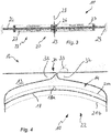
- Fig. 1-4 show different views of an flow body for manipulating a fluid, which is not shown in greater detail, flowing around a flow body 12, this entire assembly being denoted by reference sign 10.
- the fluid firstly flows around the flow body 12, and secondly is received in or may be received in a cavity 14 arranged in the flow body 12.
- the fluid passes through an opening 16 in the cavity 14, the volume of the cavity 14 being able to be changed by moving at least one wall portion 18 delimiting said cavity.
- the actuator assembly 10 has a drive unit 20 with at least one actuator 22, which moves the wall portion 18 delimiting the cavity 14 when actuated.
- the wall portion 18 is designed to be rigid and the actuator 22 manipulates the wall portion 18 indirectly when actuated.
- the cavity 14 is delimited by the wall-like upper part 13 of a housing 15, and the surrounding fluid can be drawn into, and may also leave, the cavity 14 through a slot-shaped opening 16 extending in the span direction of the flow body 12.
- the cavity 14 has an approximately teardrop-shaped profile, the approximately cubic curvature of the inner wall of the upper part of the housing wall 13 delimiting the cavity is approximately recreated by the inner wall 18a of the wall portion 18 also forming a limit of the cavity 14, with the result that the contour of the wall portion 18 is curved in the direction of the inside of the cavity, and the wall portion 18 is accordingly shaped in terms of the topology thereof in such a way that it is adapted to the shape of the at least one cavity 14 with the at least one opening 16 thereof.
- the slot arranged in the upper part 13 as an opening 16 forms an angle of approximately 45° from the general direction of the fluid flowing around the flow body 12, although the angle may also be designed to be different depending on the purpose for which the flow-control device is used.
- the wall portion 18 is rigid and provided in the cavity 14 in such a way that it can move so that fluid from the flow around the flow body 12 can be drawn into the cavity 14 and then ejected from this cavity again afterwards.
- the edges of the wall portion 18 should in this case be provided with a sealant 17 to seal the cavity 14.
- connection with a support member 24 said connection being created by a flange-like connection portion 26 with a T-shaped profile as a connecting means, said connection portion being connected to the support structure 19 of the wall portion 18 facing away from the cavity 14, in such a way that deformation of the flat support member 24 and amplification thereof can be converted into a movement of the wall portion 18.
- the support member 24 extends in parallel with the belt of said web in the span direction in each case.
- each wing of the support member 24 said surfaces facing away from but being adjacent to one another, each extend in parallel with one another between the web of the connection portion 26 and the adjacent housing wall in the span direction, the edge of said surfaces being able to be inserted in a groove 29 in said housing wall, as a result of which the ends of the support member 24 are fixed or clamped.
- the piezoelements are also attached in a flat manner onto a support structure. Limiting elements may also be used as an option to reduce or avoid shear stresses at the ends of the ceramic piezoelements.
- each surface 25a, 25b is covered by a piezoelectric surface actuator 27, and, when actuated, causes the support member 24 as a whole to be deformed in such a way that the wall portion 18 is displaced perpendicularly to the direction of excitation of the surface actuators 27.
- Each of the surface actuators 27 is composed of a plurality of piezoelectric actuators 31 arranged next to one another on the flat surface.
- FIG. 3 shows the surface actuators 27 composed of actuators 22 arranged on the surfaces 25a, 25b of the support member 24, which is clamped at the ends thereof, in greater detail.
- the situation illustrated in Fig. 3 shows that the surfaces 25a, 25b of the support member 24 extend between the grooves 29 and the web of the connection portion 26 and the majority of the span thereof is completely covered by surface actuators 27, which contract on the upper surface 25a, whereas they expand on the lower surface 25b, thus causing a movement along the direction of motion illustrated by the arrow 28.
- the excitation directions of the surface actuators 27 are reversed, resulting in a periodic movement over time of the rigid wall portion 18 between an upper displacement point and a lower displacement point 21a, 21b over time.
- Fig. 4 illustrates this movement of the rigid wall portion 18 inside the cavity 14 for the benefit of the viewer more clearly, as it shows the two displacement points 21a, 21b for the movement as dashed lines, with the curved inner wall 18a, facing the cavity 14, of the wall portion 18 of the actuator assembly 10 being visible between these lines.
- the curvature of the inner wall of the upper part 13 of the housing 15 corresponding to the curve of the inner wall 18a is also evident.
- the viewer can see the slot-like opening 16 extending into the plane of view approximately in the middle of the upper part 13.
- the fluid enters and/or is ejected from the cavity 14 at an angle inclined against the general fluid flow direction of the fluid flowing around the flow body 12 as a result of the design of the edge regions of the slot-like opening 16, which face one another, leading to an effective flow control by means of the actuator assembly 10.
- the fluid entrance and outlet at an angle 33 is achieved by the design of the edge region 30 of the slot-shaped opening 16, which is provided with edge pieces in the form of shoulders 32, which form the relevant required angle 33, although the edge region 30 itself is in turn designed to be free from edges or discontinuities on the portions thereof facing the inside of the cavity 14.
- the above-mentioned actuator assembly 10 forms a flow-control device which can be operated entirely by electrical means, and in which a fluid supply is not required.
- the optimised jet shape used in this assembly 10 is very efficient, and in some cases, if the coupled system has a low natural frequency, further resonance effects may also be utilised.
- the actuator assembly 10 also has the advantage of forming or taking up a compact installation space and representing a system that can be miniaturised.
Landscapes
- Engineering & Computer Science (AREA)
- Aviation & Aerospace Engineering (AREA)
- Chemical & Material Sciences (AREA)
- Combustion & Propulsion (AREA)
- Reciprocating Pumps (AREA)
- Micromachines (AREA)
Claims (16)
- Strömungskörper (12), umfassend:ein Gehäuse (15),wenigstens einen Hohlraum (14), der wenigstens teilweise durch eine gekrümmte Innenwand (18a) eines starren Wandabschnitts (18) und durch eine gekrümmte Innenwand eines oberen Teils (13) des Gehäuses (15) begrenzt ist, wobei die Krümmungen der gekrümmten Innenwände einander entsprechen, undeine Aktuatoranordnung (10) zum Beeinflussen eines Fluids, das um den Strömungskörper (12) herum strömt,ein Volumen des wenigstens einen Hohlraums (14), das dafür ausgelegt ist, einen Teil des Fluids aufzunehmen, derart, dass das Fluid während der Beeinflussung des Fluids durch wenigstens eine Öffnung (16) in dem wenigstens einen Hohlraum (14) strömt,wobei die Aktuatoranordnung (10) eine Antriebseinheit (20) mit wenigstens einem Aktuator (22) umfasst,wobei der Aktuator (22) mit einem Kopplungselement (26) gekoppelt ist, welches mit dem Wandabschnitt (18) verbunden ist,wobei der wenigstens eine Aktuator (22) dafür ausgelegt ist, eine periodische Bewegung über eine Zeit auszuführen, wenn er betätigt wird,derart, dass diese Bewegung eine Translationsbewegung des Wandabschnitts (18) und eine Veränderung des Volumens des wenigstens einen Hohlraums (14) bewirkt,wobei die wenigstens eine Öffnung (16) schlitzförmig ist; undwobei die Geometrie eines Randbereichs (30) der wenigstens einen Öffnung (16) gemäß einem speziellen Winkel (33) des Fluideintritts und -auslasses, der erzielt werden soll, ausgestaltet ist.
- Strömungskörper gemäß Anspruch 1,
wobei die periodische Translationsbewegung über eine Zeit, die durch den Wandabschnitt (18) ausgeführt wird, welcher den Hohlraum (14) begrenzt, derart ausgelegt ist, dass sie das Fluid schneller ausstößt als sie das Fluid ansaugt, wenn der wenigstens eine Aktuator (22) betätigt wird. - Strömungskörper gemäß Anspruch 2,
wobei die Ausstoßgeschwindigkeit die Ansauggeschwindigkeit um wenigstens 10 % und insbesondere um 10 % - 50 % übersteigt. - Strömungskörper gemäß einem der vorstehenden Ansprüche, wobei das Kopplungselement (26) mit einem Kopplungspunkt (23) am Aktuator (22) gekoppelt ist, der im Gebrauch die maximale Amplitude der periodischen Bewegung abdeckt.
- Strömungskörper gemäß Anspruch 4,
wobei der wenigstens eine Aktuator (22) der Antriebseinheit (20) wenigstens ein Unterstützungselement (24) umfasst, das mit dem Kopplungselement (26) gekoppelt ist. - Strömungskörper gemäß Anspruch 5,
wobei das wenigstens eine Unterstützungselement (24) mit wenigstens einer ebenen Fläche (25a, 25b) ausgestaltet ist, auf der ein Flächenaktuator (27) oder mehrere Flächenaktuatoren (27) ausgebildet sind, und insbesondere sind Flächenaktuatoren (27) jeweils auf Flächen (25a, 25b) ausgebildet, welche gegenüberliegend und angrenzend aneinander an beiden Seiten des ebenen Unterstützungselements (24) angeordnet sind, wobei die Flächenaktuatoren vorzugsweise einen Großteil der Flächen (25a, 25b), die mit diesen Flächenaktuatoren verknüpft sind, bedecken. - Strömungskörper gemäß einem der vorstehenden Ansprüche, wobei der wenigstens eine Aktuator (22) dafür ausgestaltet ist, elektrisch angetrieben zu werden, und als wenigstens ein piezoelektrischer Aktuator (31) oder mehrere piezoelektrische Aktuatoren (31) bereitgestellt ist.
- Strömungskörper gemäß einem der vorstehenden Ansprüche, wobei der wenigstens eine Aktuator (22) eine Bewegungsrichtung aufweist, die rechtwinklig zur Wirkrichtung des Wandabschnitts (18) ausgerichtet ist.
- Strömungskörper gemäß einem der vorstehenden Ansprüche, wobei die Öffnung (16) eine Düse bildet.
- Strömungskörper gemäß einem der vorstehenden Ansprüche, wobei der spezielle Winkel (33) zwischen ungefähr 30° und 60°, vorzugsweise ungefähr 45° liegt.
- Strömungskörper gemäß einem der vorstehenden Ansprüche, wobei sich die wenigstens eine schlitzförmige Öffnung (16) entlang der Spannrichtung des Strömungskörpers (12) für wenigstens einen Teil der Spanne davon erstreckt.
- Strömungskörper gemäß einem der vorstehenden Ansprüche, wobei die Ausdehnung der schlitzförmigen Öffnung (16) in der Spannrichtung im Wesentlichen mit der Ausdehnung des Hohlraums (14) in dieser Richtung zusammenfällt.
- Strömungskörper gemäß einem der vorstehenden Ansprüche, wobei der wenigstens eine Hohlraum (14) und/oder die wenigstens eine Öffnung (16) im Hohlraum einen im Wesentlichen rechteckigen, langgestreckten Abschnitt aufweisen.
- Strömungskörper gemäß einem der vorstehenden Ansprüche, wobei die ebene Ausdehnung der Öffnung (16) oder des Hohlraums (14) in jedem Fall derart ausgestaltet ist, dass sie größer als die Ausdehnung davon in der Bewegungsrichtung des Wandabschnitts (18) ist.
- Strömungsregelungsvorrichtung mit einem Strömungskörper (12) gemäß einem der vorstehenden Ansprüche und mit wenigstens einer Regelvorrichtung, um aktiv und steuerbar das Strömungsverhalten zu beeinflussen.
- Verfahren zur Strömungsregelung an einem Strömungskörper (12) gemäß einem der Ansprüche 1-14, wobei der Strömungskörper (12) insbesondere mit einer Flugvorrichtung oder einem Flugzeug oder einem Raumfahrzeug verknüpft ist.
Applications Claiming Priority (1)
| Application Number | Priority Date | Filing Date | Title |
|---|---|---|---|
| DE102016205620.4A DE102016205620A1 (de) | 2016-04-05 | 2016-04-05 | Aktuator-Anordnung |
Publications (2)
| Publication Number | Publication Date |
|---|---|
| EP3228538A1 EP3228538A1 (de) | 2017-10-11 |
| EP3228538B1 true EP3228538B1 (de) | 2019-07-31 |
Family
ID=58530384
Family Applications (1)
| Application Number | Title | Priority Date | Filing Date |
|---|---|---|---|
| EP17164928.8A Active EP3228538B1 (de) | 2016-04-05 | 2017-04-05 | Aktuatoranordnung |
Country Status (3)
| Country | Link |
|---|---|
| US (1) | US10556669B2 (de) |
| EP (1) | EP3228538B1 (de) |
| DE (1) | DE102016205620A1 (de) |
Cited By (1)
| Publication number | Priority date | Publication date | Assignee | Title |
|---|---|---|---|---|
| US10556669B2 (en) | 2016-04-05 | 2020-02-11 | Airbus Defence and Space GmbH | Actuator assembly |
Families Citing this family (1)
| Publication number | Priority date | Publication date | Assignee | Title |
|---|---|---|---|---|
| US20210197223A1 (en) * | 2019-12-29 | 2021-07-01 | Actasys, Inc. | Production Technique of Synthetic Jet Actuators |
Family Cites Families (20)
| Publication number | Priority date | Publication date | Assignee | Title |
|---|---|---|---|---|
| US4285482A (en) * | 1979-08-10 | 1981-08-25 | The Boeing Company | Wing leading edge high lift device |
| US6123145A (en) * | 1995-06-12 | 2000-09-26 | Georgia Tech Research Corporation | Synthetic jet actuators for cooling heated bodies and environments |
| US6457654B1 (en) * | 1995-06-12 | 2002-10-01 | Georgia Tech Research Corporation | Micromachined synthetic jet actuators and applications thereof |
| US5758823A (en) * | 1995-06-12 | 1998-06-02 | Georgia Tech Research Corporation | Synthetic jet actuator and applications thereof |
| DE19735156C1 (de) * | 1996-11-25 | 1999-04-29 | Fraunhofer Ges Forschung | Piezoelektrisch betätigtes Mikroventil |
| US7246529B1 (en) * | 2006-08-03 | 2007-07-24 | The Boeing Company | Oscillating vane actuator apparatus and method for active flow control |
| US7823839B2 (en) * | 2005-10-31 | 2010-11-02 | Georgia Tech Research Corporation | Airfoil performance modification using synthetic jet actuators |
| AU2007317415A1 (en) * | 2006-11-02 | 2008-05-15 | The University Of Notre Dame Du Lac | Methods and apparatus for reducing drag via a plasma actuator |
| DE102008017963B4 (de) * | 2008-04-08 | 2016-10-06 | Airbus Defence and Space GmbH | Strömungssteuerungsbauelement |
| US8251317B2 (en) * | 2008-04-18 | 2012-08-28 | The Boeing Company | System and method for varying the porosity of an aerodynamic surface |
| US8662412B2 (en) * | 2008-08-25 | 2014-03-04 | The United States Of America As Represented By The Administrator Of The National Aeronautics And Space Administration | Advanced modified high performance synthetic jet actuator with curved chamber |
| DE102009060325A1 (de) * | 2009-12-23 | 2011-06-30 | Airbus Operations GmbH, 21129 | Hochauftriebssystem für ein Flugzeug |
| DE102010046667A1 (de) * | 2010-09-27 | 2012-03-29 | Airbus Operations Gmbh | Fluid-Aktuator zur Beeinflussung der Strömung entlang einer Strömungsoberfläche sowie Ausblasvorrichtung und Strömungskörper mit einem solchen Fluid-Aktuator |
| DE102010048123B4 (de) * | 2010-10-11 | 2022-04-21 | Airbus Operations Gmbh | Fluid-Aktuator zur Beeinflussung der Strömung entlang einer Strömungsoberfläche sowie Ausblasvorrichtung und Strömungskörper mit einem solchen Fluid-Aktuator |
| FR2968735B1 (fr) * | 2010-12-14 | 2014-03-14 | Onera Office National Detudes Et De Rech Aerospatiales | Micro-generateur fluidique de jets synthetiques. |
| US9718538B2 (en) * | 2011-10-27 | 2017-08-01 | Ramot At Tel-Aviv University Ltd. | Synchronization of fluidic actuators |
| EP2650213B1 (de) * | 2012-04-12 | 2014-07-16 | Airbus Operations GmbH | Strömungskörper mit einer Vorderkante, einer Oberfläche und einem aktiven Strömungssteuerungssystem und Fahrzeug mit mindestens einem solchen Strömungskörper und einer Luftquelle |
| US9162754B2 (en) * | 2012-04-27 | 2015-10-20 | General Electric Company | Method of using an active flow control system for lift enhancement or destruction in a wind turbine blade |
| US9346536B2 (en) * | 2012-10-16 | 2016-05-24 | The Boeing Company | Externally driven flow control actuator |
| DE102016205620A1 (de) | 2016-04-05 | 2017-10-05 | Airbus Defence and Space GmbH | Aktuator-Anordnung |
-
2016
- 2016-04-05 DE DE102016205620.4A patent/DE102016205620A1/de not_active Ceased
-
2017
- 2017-04-05 EP EP17164928.8A patent/EP3228538B1/de active Active
- 2017-04-05 US US15/479,649 patent/US10556669B2/en active Active
Non-Patent Citations (1)
| Title |
|---|
| None * |
Cited By (1)
| Publication number | Priority date | Publication date | Assignee | Title |
|---|---|---|---|---|
| US10556669B2 (en) | 2016-04-05 | 2020-02-11 | Airbus Defence and Space GmbH | Actuator assembly |
Also Published As
| Publication number | Publication date |
|---|---|
| EP3228538A1 (de) | 2017-10-11 |
| DE102016205620A1 (de) | 2017-10-05 |
| US20170283043A1 (en) | 2017-10-05 |
| US10556669B2 (en) | 2020-02-11 |
Similar Documents
| Publication | Publication Date | Title |
|---|---|---|
| DK2841338T3 (en) | PROCEDURE FOR USING AN ACTIVE FLOW MANAGEMENT SYSTEM FOR OPERATING IMPROVEMENT OR DESTRUCTION | |
| JP5344917B2 (ja) | 空気力学的流れのためのシステムおよび関連する方法 | |
| TWI595738B (zh) | 微機電系統及其相關系統、用途、微機電系統揚聲器和調節單元 | |
| US20020081198A1 (en) | Jet actuators for aerodynamic surfaces | |
| US6722581B2 (en) | Synthetic jet actuators | |
| US8226047B2 (en) | Reduction of tip vortex and wake interaction effects in energy and propulsion systems | |
| US8235309B2 (en) | Advanced high performance horizontal piezoelectric hybrid synthetic jet actuator | |
| Bilgen et al. | Macro-fiber composite actuated simply supported thin airfoils | |
| US20140216696A1 (en) | Cooling device and a cooling assembly comprising the cooling device | |
| US10556669B2 (en) | Actuator assembly | |
| EP2966700B1 (de) | Orthotropes bimorphelement für verbesserte leistung eines synthetischen strahls | |
| US20140238522A1 (en) | Piezoelectric driven oscillating surface | |
| EP2628946A1 (de) | Aerodynamisches Blatt und Verfahren zum Steuern des Auftriebs des Blattes | |
| US8662412B2 (en) | Advanced modified high performance synthetic jet actuator with curved chamber | |
| Chang et al. | Design, analysis and optimization of an electromagnetic actuator for a micro impedance pump | |
| US7055541B2 (en) | Method and mechanism for producing suction and periodic excitation flow | |
| CN108779864A (zh) | 流路切换阀和其制造方法 | |
| Bolzmacher et al. | Displacement amplification of piezoelectric microactuators with a micromachined leverage unit | |
| Rediniotis et al. | Active skin for turbulent drag reduction | |
| KR101301484B1 (ko) | 압전 밸브 | |
| Behlert et al. | Design of an integrated piezoelectric micro-flapper based on bionic principles | |
| Sinha et al. | Control of flow separation using the EMEMS approach: proof of concept experiments | |
| JP2014013019A (ja) | ピエゾファン | |
| Haller et al. | A piezo-actuated closed loop MEMS system for active delay of transition | |
| CN117622477A (zh) | 一种基于流动控制的变频振荡射流装置及其控制方法 |
Legal Events
| Date | Code | Title | Description |
|---|---|---|---|
| PUAI | Public reference made under article 153(3) epc to a published international application that has entered the european phase |
Free format text: ORIGINAL CODE: 0009012 |
|
| STAA | Information on the status of an ep patent application or granted ep patent |
Free format text: STATUS: THE APPLICATION HAS BEEN PUBLISHED |
|
| AK | Designated contracting states |
Kind code of ref document: A1 Designated state(s): AL AT BE BG CH CY CZ DE DK EE ES FI FR GB GR HR HU IE IS IT LI LT LU LV MC MK MT NL NO PL PT RO RS SE SI SK SM TR |
|
| AX | Request for extension of the european patent |
Extension state: BA ME |
|
| STAA | Information on the status of an ep patent application or granted ep patent |
Free format text: STATUS: REQUEST FOR EXAMINATION WAS MADE |
|
| 17P | Request for examination filed |
Effective date: 20180409 |
|
| RBV | Designated contracting states (corrected) |
Designated state(s): AL AT BE BG CH CY CZ DE DK EE ES FI FR GB GR HR HU IE IS IT LI LT LU LV MC MK MT NL NO PL PT RO RS SE SI SK SM TR |
|
| STAA | Information on the status of an ep patent application or granted ep patent |
Free format text: STATUS: EXAMINATION IS IN PROGRESS |
|
| 17Q | First examination report despatched |
Effective date: 20180615 |
|
| GRAP | Despatch of communication of intention to grant a patent |
Free format text: ORIGINAL CODE: EPIDOSNIGR1 |
|
| STAA | Information on the status of an ep patent application or granted ep patent |
Free format text: STATUS: GRANT OF PATENT IS INTENDED |
|
| INTG | Intention to grant announced |
Effective date: 20190321 |
|
| GRAS | Grant fee paid |
Free format text: ORIGINAL CODE: EPIDOSNIGR3 |
|
| GRAA | (expected) grant |
Free format text: ORIGINAL CODE: 0009210 |
|
| STAA | Information on the status of an ep patent application or granted ep patent |
Free format text: STATUS: THE PATENT HAS BEEN GRANTED |
|
| AK | Designated contracting states |
Kind code of ref document: B1 Designated state(s): AL AT BE BG CH CY CZ DE DK EE ES FI FR GB GR HR HU IE IS IT LI LT LU LV MC MK MT NL NO PL PT RO RS SE SI SK SM TR |
|
| REG | Reference to a national code |
Ref country code: CH Ref legal event code: EP Ref country code: GB Ref legal event code: FG4D |
|
| REG | Reference to a national code |
Ref country code: DE Ref legal event code: R096 Ref document number: 602017005619 Country of ref document: DE |
|
| REG | Reference to a national code |
Ref country code: AT Ref legal event code: REF Ref document number: 1160611 Country of ref document: AT Kind code of ref document: T Effective date: 20190815 |
|
| REG | Reference to a national code |
Ref country code: IE Ref legal event code: FG4D |
|
| REG | Reference to a national code |
Ref country code: NL Ref legal event code: MP Effective date: 20190731 |
|
| REG | Reference to a national code |
Ref country code: LT Ref legal event code: MG4D |
|
| REG | Reference to a national code |
Ref country code: AT Ref legal event code: MK05 Ref document number: 1160611 Country of ref document: AT Kind code of ref document: T Effective date: 20190731 |
|
| PG25 | Lapsed in a contracting state [announced via postgrant information from national office to epo] |
Ref country code: BG Free format text: LAPSE BECAUSE OF FAILURE TO SUBMIT A TRANSLATION OF THE DESCRIPTION OR TO PAY THE FEE WITHIN THE PRESCRIBED TIME-LIMIT Effective date: 20191031 Ref country code: PT Free format text: LAPSE BECAUSE OF FAILURE TO SUBMIT A TRANSLATION OF THE DESCRIPTION OR TO PAY THE FEE WITHIN THE PRESCRIBED TIME-LIMIT Effective date: 20191202 Ref country code: NL Free format text: LAPSE BECAUSE OF FAILURE TO SUBMIT A TRANSLATION OF THE DESCRIPTION OR TO PAY THE FEE WITHIN THE PRESCRIBED TIME-LIMIT Effective date: 20190731 Ref country code: LT Free format text: LAPSE BECAUSE OF FAILURE TO SUBMIT A TRANSLATION OF THE DESCRIPTION OR TO PAY THE FEE WITHIN THE PRESCRIBED TIME-LIMIT Effective date: 20190731 Ref country code: HR Free format text: LAPSE BECAUSE OF FAILURE TO SUBMIT A TRANSLATION OF THE DESCRIPTION OR TO PAY THE FEE WITHIN THE PRESCRIBED TIME-LIMIT Effective date: 20190731 Ref country code: AT Free format text: LAPSE BECAUSE OF FAILURE TO SUBMIT A TRANSLATION OF THE DESCRIPTION OR TO PAY THE FEE WITHIN THE PRESCRIBED TIME-LIMIT Effective date: 20190731 Ref country code: NO Free format text: LAPSE BECAUSE OF FAILURE TO SUBMIT A TRANSLATION OF THE DESCRIPTION OR TO PAY THE FEE WITHIN THE PRESCRIBED TIME-LIMIT Effective date: 20191031 Ref country code: FI Free format text: LAPSE BECAUSE OF FAILURE TO SUBMIT A TRANSLATION OF THE DESCRIPTION OR TO PAY THE FEE WITHIN THE PRESCRIBED TIME-LIMIT Effective date: 20190731 Ref country code: SE Free format text: LAPSE BECAUSE OF FAILURE TO SUBMIT A TRANSLATION OF THE DESCRIPTION OR TO PAY THE FEE WITHIN THE PRESCRIBED TIME-LIMIT Effective date: 20190731 |
|
| PG25 | Lapsed in a contracting state [announced via postgrant information from national office to epo] |
Ref country code: AL Free format text: LAPSE BECAUSE OF FAILURE TO SUBMIT A TRANSLATION OF THE DESCRIPTION OR TO PAY THE FEE WITHIN THE PRESCRIBED TIME-LIMIT Effective date: 20190731 Ref country code: IS Free format text: LAPSE BECAUSE OF FAILURE TO SUBMIT A TRANSLATION OF THE DESCRIPTION OR TO PAY THE FEE WITHIN THE PRESCRIBED TIME-LIMIT Effective date: 20191130 Ref country code: RS Free format text: LAPSE BECAUSE OF FAILURE TO SUBMIT A TRANSLATION OF THE DESCRIPTION OR TO PAY THE FEE WITHIN THE PRESCRIBED TIME-LIMIT Effective date: 20190731 Ref country code: LV Free format text: LAPSE BECAUSE OF FAILURE TO SUBMIT A TRANSLATION OF THE DESCRIPTION OR TO PAY THE FEE WITHIN THE PRESCRIBED TIME-LIMIT Effective date: 20190731 Ref country code: ES Free format text: LAPSE BECAUSE OF FAILURE TO SUBMIT A TRANSLATION OF THE DESCRIPTION OR TO PAY THE FEE WITHIN THE PRESCRIBED TIME-LIMIT Effective date: 20190731 Ref country code: GR Free format text: LAPSE BECAUSE OF FAILURE TO SUBMIT A TRANSLATION OF THE DESCRIPTION OR TO PAY THE FEE WITHIN THE PRESCRIBED TIME-LIMIT Effective date: 20191101 |
|
| PG25 | Lapsed in a contracting state [announced via postgrant information from national office to epo] |
Ref country code: TR Free format text: LAPSE BECAUSE OF FAILURE TO SUBMIT A TRANSLATION OF THE DESCRIPTION OR TO PAY THE FEE WITHIN THE PRESCRIBED TIME-LIMIT Effective date: 20190731 |
|
| PG25 | Lapsed in a contracting state [announced via postgrant information from national office to epo] |
Ref country code: IT Free format text: LAPSE BECAUSE OF FAILURE TO SUBMIT A TRANSLATION OF THE DESCRIPTION OR TO PAY THE FEE WITHIN THE PRESCRIBED TIME-LIMIT Effective date: 20190731 Ref country code: RO Free format text: LAPSE BECAUSE OF FAILURE TO SUBMIT A TRANSLATION OF THE DESCRIPTION OR TO PAY THE FEE WITHIN THE PRESCRIBED TIME-LIMIT Effective date: 20190731 Ref country code: EE Free format text: LAPSE BECAUSE OF FAILURE TO SUBMIT A TRANSLATION OF THE DESCRIPTION OR TO PAY THE FEE WITHIN THE PRESCRIBED TIME-LIMIT Effective date: 20190731 Ref country code: DK Free format text: LAPSE BECAUSE OF FAILURE TO SUBMIT A TRANSLATION OF THE DESCRIPTION OR TO PAY THE FEE WITHIN THE PRESCRIBED TIME-LIMIT Effective date: 20190731 Ref country code: PL Free format text: LAPSE BECAUSE OF FAILURE TO SUBMIT A TRANSLATION OF THE DESCRIPTION OR TO PAY THE FEE WITHIN THE PRESCRIBED TIME-LIMIT Effective date: 20190731 |
|
| PG25 | Lapsed in a contracting state [announced via postgrant information from national office to epo] |
Ref country code: CZ Free format text: LAPSE BECAUSE OF FAILURE TO SUBMIT A TRANSLATION OF THE DESCRIPTION OR TO PAY THE FEE WITHIN THE PRESCRIBED TIME-LIMIT Effective date: 20190731 Ref country code: SK Free format text: LAPSE BECAUSE OF FAILURE TO SUBMIT A TRANSLATION OF THE DESCRIPTION OR TO PAY THE FEE WITHIN THE PRESCRIBED TIME-LIMIT Effective date: 20190731 Ref country code: IS Free format text: LAPSE BECAUSE OF FAILURE TO SUBMIT A TRANSLATION OF THE DESCRIPTION OR TO PAY THE FEE WITHIN THE PRESCRIBED TIME-LIMIT Effective date: 20200224 Ref country code: SM Free format text: LAPSE BECAUSE OF FAILURE TO SUBMIT A TRANSLATION OF THE DESCRIPTION OR TO PAY THE FEE WITHIN THE PRESCRIBED TIME-LIMIT Effective date: 20190731 |
|
| REG | Reference to a national code |
Ref country code: DE Ref legal event code: R097 Ref document number: 602017005619 Country of ref document: DE |
|
| PLBE | No opposition filed within time limit |
Free format text: ORIGINAL CODE: 0009261 |
|
| STAA | Information on the status of an ep patent application or granted ep patent |
Free format text: STATUS: NO OPPOSITION FILED WITHIN TIME LIMIT |
|
| PG2D | Information on lapse in contracting state deleted |
Ref country code: IS |
|
| PG25 | Lapsed in a contracting state [announced via postgrant information from national office to epo] |
Ref country code: IS Free format text: LAPSE BECAUSE OF FAILURE TO SUBMIT A TRANSLATION OF THE DESCRIPTION OR TO PAY THE FEE WITHIN THE PRESCRIBED TIME-LIMIT Effective date: 20191030 |
|
| PGFP | Annual fee paid to national office [announced via postgrant information from national office to epo] |
Ref country code: DE Payment date: 20200420 Year of fee payment: 4 Ref country code: FR Payment date: 20200420 Year of fee payment: 4 |
|
| 26N | No opposition filed |
Effective date: 20200603 |
|
| PG25 | Lapsed in a contracting state [announced via postgrant information from national office to epo] |
Ref country code: SI Free format text: LAPSE BECAUSE OF FAILURE TO SUBMIT A TRANSLATION OF THE DESCRIPTION OR TO PAY THE FEE WITHIN THE PRESCRIBED TIME-LIMIT Effective date: 20190731 |
|
| PG25 | Lapsed in a contracting state [announced via postgrant information from national office to epo] |
Ref country code: MC Free format text: LAPSE BECAUSE OF FAILURE TO SUBMIT A TRANSLATION OF THE DESCRIPTION OR TO PAY THE FEE WITHIN THE PRESCRIBED TIME-LIMIT Effective date: 20190731 |
|
| REG | Reference to a national code |
Ref country code: CH Ref legal event code: PL |
|
| PG25 | Lapsed in a contracting state [announced via postgrant information from national office to epo] |
Ref country code: LI Free format text: LAPSE BECAUSE OF NON-PAYMENT OF DUE FEES Effective date: 20200430 Ref country code: LU Free format text: LAPSE BECAUSE OF NON-PAYMENT OF DUE FEES Effective date: 20200405 Ref country code: CH Free format text: LAPSE BECAUSE OF NON-PAYMENT OF DUE FEES Effective date: 20200430 |
|
| REG | Reference to a national code |
Ref country code: BE Ref legal event code: MM Effective date: 20200430 |
|
| PG25 | Lapsed in a contracting state [announced via postgrant information from national office to epo] |
Ref country code: BE Free format text: LAPSE BECAUSE OF NON-PAYMENT OF DUE FEES Effective date: 20200430 |
|
| PG25 | Lapsed in a contracting state [announced via postgrant information from national office to epo] |
Ref country code: IE Free format text: LAPSE BECAUSE OF NON-PAYMENT OF DUE FEES Effective date: 20200405 |
|
| REG | Reference to a national code |
Ref country code: DE Ref legal event code: R119 Ref document number: 602017005619 Country of ref document: DE |
|
| GBPC | Gb: european patent ceased through non-payment of renewal fee |
Effective date: 20210405 |
|
| PG25 | Lapsed in a contracting state [announced via postgrant information from national office to epo] |
Ref country code: DE Free format text: LAPSE BECAUSE OF NON-PAYMENT OF DUE FEES Effective date: 20211103 Ref country code: GB Free format text: LAPSE BECAUSE OF NON-PAYMENT OF DUE FEES Effective date: 20210405 Ref country code: FR Free format text: LAPSE BECAUSE OF NON-PAYMENT OF DUE FEES Effective date: 20210430 |
|
| PG25 | Lapsed in a contracting state [announced via postgrant information from national office to epo] |
Ref country code: MT Free format text: LAPSE BECAUSE OF FAILURE TO SUBMIT A TRANSLATION OF THE DESCRIPTION OR TO PAY THE FEE WITHIN THE PRESCRIBED TIME-LIMIT Effective date: 20190731 Ref country code: CY Free format text: LAPSE BECAUSE OF FAILURE TO SUBMIT A TRANSLATION OF THE DESCRIPTION OR TO PAY THE FEE WITHIN THE PRESCRIBED TIME-LIMIT Effective date: 20190731 |
|
| PG25 | Lapsed in a contracting state [announced via postgrant information from national office to epo] |
Ref country code: MK Free format text: LAPSE BECAUSE OF FAILURE TO SUBMIT A TRANSLATION OF THE DESCRIPTION OR TO PAY THE FEE WITHIN THE PRESCRIBED TIME-LIMIT Effective date: 20190731 |