EP3228531B1 - Marine structure platform having movement damping function and submersible marine structure having same - Google Patents
Marine structure platform having movement damping function and submersible marine structure having same Download PDFInfo
- Publication number
- EP3228531B1 EP3228531B1 EP15865473.1A EP15865473A EP3228531B1 EP 3228531 B1 EP3228531 B1 EP 3228531B1 EP 15865473 A EP15865473 A EP 15865473A EP 3228531 B1 EP3228531 B1 EP 3228531B1
- Authority
- EP
- European Patent Office
- Prior art keywords
- movement damping
- marine structure
- shape
- pair
- connecting parts
- Prior art date
- Legal status (The legal status is an assumption and is not a legal conclusion. Google has not performed a legal analysis and makes no representation as to the accuracy of the status listed.)
- Active
Links
Images




Classifications
-
- B—PERFORMING OPERATIONS; TRANSPORTING
- B63—SHIPS OR OTHER WATERBORNE VESSELS; RELATED EQUIPMENT
- B63B—SHIPS OR OTHER WATERBORNE VESSELS; EQUIPMENT FOR SHIPPING
- B63B1/00—Hydrodynamic or hydrostatic features of hulls or of hydrofoils
- B63B1/02—Hydrodynamic or hydrostatic features of hulls or of hydrofoils deriving lift mainly from water displacement
- B63B1/10—Hydrodynamic or hydrostatic features of hulls or of hydrofoils deriving lift mainly from water displacement with multiple hulls
- B63B1/107—Semi-submersibles; Small waterline area multiple hull vessels and the like, e.g. SWATH
-
- B—PERFORMING OPERATIONS; TRANSPORTING
- B63—SHIPS OR OTHER WATERBORNE VESSELS; RELATED EQUIPMENT
- B63B—SHIPS OR OTHER WATERBORNE VESSELS; EQUIPMENT FOR SHIPPING
- B63B1/00—Hydrodynamic or hydrostatic features of hulls or of hydrofoils
- B63B1/32—Other means for varying the inherent hydrodynamic characteristics of hulls
- B63B1/40—Other means for varying the inherent hydrodynamic characteristics of hulls by diminishing wave resistance
-
- B—PERFORMING OPERATIONS; TRANSPORTING
- B63—SHIPS OR OTHER WATERBORNE VESSELS; RELATED EQUIPMENT
- B63B—SHIPS OR OTHER WATERBORNE VESSELS; EQUIPMENT FOR SHIPPING
- B63B35/00—Vessels or similar floating structures specially adapted for specific purposes and not otherwise provided for
- B63B35/44—Floating buildings, stores, drilling platforms, or workshops, e.g. carrying water-oil separating devices
-
- B—PERFORMING OPERATIONS; TRANSPORTING
- B63—SHIPS OR OTHER WATERBORNE VESSELS; RELATED EQUIPMENT
- B63B—SHIPS OR OTHER WATERBORNE VESSELS; EQUIPMENT FOR SHIPPING
- B63B35/00—Vessels or similar floating structures specially adapted for specific purposes and not otherwise provided for
- B63B35/44—Floating buildings, stores, drilling platforms, or workshops, e.g. carrying water-oil separating devices
- B63B35/4413—Floating drilling platforms, e.g. carrying water-oil separating devices
-
- B—PERFORMING OPERATIONS; TRANSPORTING
- B63—SHIPS OR OTHER WATERBORNE VESSELS; RELATED EQUIPMENT
- B63B—SHIPS OR OTHER WATERBORNE VESSELS; EQUIPMENT FOR SHIPPING
- B63B39/00—Equipment to decrease pitch, roll, or like unwanted vessel movements; Apparatus for indicating vessel attitude
-
- B—PERFORMING OPERATIONS; TRANSPORTING
- B63—SHIPS OR OTHER WATERBORNE VESSELS; RELATED EQUIPMENT
- B63B—SHIPS OR OTHER WATERBORNE VESSELS; EQUIPMENT FOR SHIPPING
- B63B39/00—Equipment to decrease pitch, roll, or like unwanted vessel movements; Apparatus for indicating vessel attitude
- B63B39/10—Equipment to decrease pitch, roll, or like unwanted vessel movements; Apparatus for indicating vessel attitude to decrease vessel movements by damping the waves, e.g. by pouring oil on water
-
- B—PERFORMING OPERATIONS; TRANSPORTING
- B63—SHIPS OR OTHER WATERBORNE VESSELS; RELATED EQUIPMENT
- B63B—SHIPS OR OTHER WATERBORNE VESSELS; EQUIPMENT FOR SHIPPING
- B63B43/00—Improving safety of vessels, e.g. damage control, not otherwise provided for
- B63B43/02—Improving safety of vessels, e.g. damage control, not otherwise provided for reducing risk of capsizing or sinking
-
- E—FIXED CONSTRUCTIONS
- E21—EARTH OR ROCK DRILLING; MINING
- E21B—EARTH OR ROCK DRILLING; OBTAINING OIL, GAS, WATER, SOLUBLE OR MELTABLE MATERIALS OR A SLURRY OF MINERALS FROM WELLS
- E21B15/00—Supports for the drilling machine, e.g. derricks or masts
- E21B15/02—Supports for the drilling machine, e.g. derricks or masts specially adapted for underwater drilling
-
- E—FIXED CONSTRUCTIONS
- E21—EARTH OR ROCK DRILLING; MINING
- E21B—EARTH OR ROCK DRILLING; OBTAINING OIL, GAS, WATER, SOLUBLE OR MELTABLE MATERIALS OR A SLURRY OF MINERALS FROM WELLS
- E21B7/00—Special methods or apparatus for drilling
- E21B7/12—Underwater drilling
-
- B—PERFORMING OPERATIONS; TRANSPORTING
- B63—SHIPS OR OTHER WATERBORNE VESSELS; RELATED EQUIPMENT
- B63B—SHIPS OR OTHER WATERBORNE VESSELS; EQUIPMENT FOR SHIPPING
- B63B1/00—Hydrodynamic or hydrostatic features of hulls or of hydrofoils
- B63B1/02—Hydrodynamic or hydrostatic features of hulls or of hydrofoils deriving lift mainly from water displacement
- B63B1/10—Hydrodynamic or hydrostatic features of hulls or of hydrofoils deriving lift mainly from water displacement with multiple hulls
- B63B1/12—Hydrodynamic or hydrostatic features of hulls or of hydrofoils deriving lift mainly from water displacement with multiple hulls the hulls being interconnected rigidly
- B63B2001/128—Hydrodynamic or hydrostatic features of hulls or of hydrofoils deriving lift mainly from water displacement with multiple hulls the hulls being interconnected rigidly comprising underwater connectors between the hulls
-
- B—PERFORMING OPERATIONS; TRANSPORTING
- B63—SHIPS OR OTHER WATERBORNE VESSELS; RELATED EQUIPMENT
- B63B—SHIPS OR OTHER WATERBORNE VESSELS; EQUIPMENT FOR SHIPPING
- B63B35/00—Vessels or similar floating structures specially adapted for specific purposes and not otherwise provided for
- B63B35/44—Floating buildings, stores, drilling platforms, or workshops, e.g. carrying water-oil separating devices
- B63B2035/442—Spar-type semi-submersible structures, i.e. shaped as single slender, e.g. substantially cylindrical or trussed vertical bodies
-
- B—PERFORMING OPERATIONS; TRANSPORTING
- B63—SHIPS OR OTHER WATERBORNE VESSELS; RELATED EQUIPMENT
- B63B—SHIPS OR OTHER WATERBORNE VESSELS; EQUIPMENT FOR SHIPPING
- B63B39/00—Equipment to decrease pitch, roll, or like unwanted vessel movements; Apparatus for indicating vessel attitude
- B63B39/06—Equipment to decrease pitch, roll, or like unwanted vessel movements; Apparatus for indicating vessel attitude to decrease vessel movements by using foils acting on ambient water
- B63B2039/067—Equipment to decrease pitch, roll, or like unwanted vessel movements; Apparatus for indicating vessel attitude to decrease vessel movements by using foils acting on ambient water effecting motion dampening by means of fixed or movable resistance bodies, e.g. by bilge keels
Definitions
- the present invention relates to a marine structure, and more particularly, to a marine structure platform having a movement damping function capable of efficiently damping a heaving motion, a rolling motion, and a pitching motion of the marine structure platform on the sea, and to a semi-submersible marine structure respectively.
- a semi-submersible marine structure such as a combined cycle power generation structure on the sea, has a high-priced drilling system for performing drilling operations on an upper deck, and the semi-submersible marine structure is moored at a predetermined location and floats in the sea.
- the semi-submersible marine structure since the semi-submersible marine structure is in use while floating in the sea, the semi-submersible marine structure is inevitably moved due to a flow of seawater.
- An object of the present invention is to provide a marine structure platform having a movement damping function capable of efficiently damping a heaving motion, a rolling motion, and a pitching motion on the sea, and enabling a marine structure to be stably moored on the sea, and a semi-submersible marine structure respectively.
- Another object of the present invention is to provide a marine structure platform having a movement damping function capable of improving supporting force at a portion where a pontoon and a column are connected to each other, and ensuring stability of a structure on the sea, and a semi-submersible marine structure respectively.
- the present invention provides a marine structure platform according to claim 1 .
- the movement damping part includes a pair of movement damping plates which defines the gap and may be opened along an interior of the horizontal connecting parts.
- Outer circumferences of the pair of movement damping plates surrounded by the horizontal connecting parts may be formed in a polygonal shape, a circular shape, or a fan shape.
- a vortex inducing hole is formed in the pair of movement damping plates so as to vertically penetrate the pair of movement damping plates.
- the vortex inducing hole is formed to expose a part of the vertical connecting part.
- a part of an inner circumference of the vortex inducing hole surrounded by the horizontal connecting parts may be formed to have a shape corresponding to a shape of an outer circumference of each of the pair of movement damping plates.
- One or more vertical reinforcing members are installed in a space between the pair of movement damping plates so as to connect and support the pair of movement damping plates.
- the vertical reinforcing member may be formed in a cylindrical shape, a circular column shape, a quadrangular container shape, a square column shape, or an I-beam shape.
- a radial reinforcing member is formed on at least one of the pair of movement damping plates.
- the radial reinforcing member is formed along an inner surface of the movement damping plate so as to connect a circumference of the vertical reinforcing member and a circumference of the movement damping plate.
- the present invention provides a semi-submersible marine structure including the marine structure platform.
- the present invention it is possible to efficiently damp a heaving motion, a rolling motion, and a pitching motion on the sea, thereby enabling the marine structure to be stably moored.
- the marine structure according to the present invention is a semi-submersible marine structure which is a facility that is moored on the sea and performs combined cycle power generation.
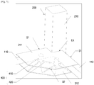
- FIG. 1 is a perspective view illustrating a marine structure platform
- FIG. 2 is an enlarged perspective view of part A in FIG. 1
- FIG. 3 is a view illustrating a state before movement damping plates are coupled.
- the marine structure according to the present invention has a marine structure platform.
- the marine structure platform broadly includes horizontal connecting parts 100, vertical connecting parts 200, and movement damping parts 300.
- the horizontal connecting parts 100 have a lattice structure, and the horizontal connecting parts 100 are disposed on the sea.
- the horizontal connecting parts 100 include pontoons 110.
- the horizontal connecting parts 100 include the pontoons 110 that define a frame having a lattice structure.
- the vertical connecting part 200 is configured as a column 210 having a shape like a vertical frame.
- the vertical connecting parts 200 are installed at four corners of the horizontal connecting parts 100 so as to be perpendicular to the horizontal connecting parts 100.
- the four vertical connecting parts 200 may protrude from the sea at the four corners of the horizontal connecting parts 100.
- a deck of the marine structure may be installed at an upper end of each of the vertical connecting parts 200.
- each of the four sections includes the two pontoons 110, and the single column 210 perpendicular to a corner between the two pontoons 110.
- corner regions EA are formed between the horizontal connecting parts 100 and the vertical connecting parts 200 according to the present invention.
- the movement damping parts 300 according to the present invention are installed in the four corner regions EA.
- the movement damping part 300 includes a pair of movement damping plates 310.
- the pair of movement damping plates 310 may have the same size and the same shape.
- the movement damping plate 310 has a plate body which includes a pair of connecting surfaces S1 that form a right angle therebetween, and a circumferential surface S2 that connects the pair of connecting surfaces S1 so as to define an outer circumference.
- one corner of the plate body is connected to the column 210, and the pair of connecting surfaces S1 is extended from one corner along the two pontoons 110 adjacent to the plate body.
- circumferential surface S2 is formed in a polygonal shape, and particularly, the circumferential surface S2 may be cut out to define three surfaces.
- the corner of the plate body is formed to be fitted with a circumference with the corresponding column 210, and the corner of the plate body may be connected to the column 210 by welding.
- the portions, which define the connecting surfaces S1 of the plate body may be installed on upper or lower surfaces of the two pontoons 110 by welding.
- the pair of movement damping plates 310 includes an upper movement damping plate 311 and a lower movement damping plate 312.
- the upper and lower movement damping plates 311 and 312 have the same shape, and the upper and lower movement damping plates 311 and 312 are installed in each of the corner regions EA.
- the upper movement damping plate 311 is installed on the upper surfaces of the two pontoons 110 in the corresponding corner region EA, and the lower movement damping plate 312 is installed on the lower surfaces of the two pontoons 210 in the corresponding corner region EA.
- the upper and lower movement damping plates 311 and 312 are disposed to face each other vertically.
- a space having a gap G is formed between the upper and lower movement damping plates 311 and 312, and the space is opened toward one side.
- supporting force may be increased since the movement damping plates 310 are installed on the upper and lower surfaces of the two pontoons 110, respectively, in each of the four corner regions EA as described above.
- the reason why the upper and lower movement damping plates 311 and 312 are attached to the upper and lower surfaces of the pontoons 11 is to form only a thickness of a shell of the movement damping plates 310 by allowing the upper and lower movement damping plates 311 and 312 to be individually separated and spaced apart from each other, thereby reducing a thickness of a location at which a vortex occurs in comparison with a case in which a movement damping plate is installed only at a lower side of the pontoon 110.
- the occurrence of the vortex is decreased as the thickness of the movement damping plates 310 is increased, such that viscous damping is decreased.
- the occurrence of the vortex is increased, such that the viscous damping may be increased, and a movement reducing effect may be maximized.
- the movement damping plates 310 instead of a single plate, are configured to be separated from each other vertically in each of the corner regions EA, and this configuration may be advantageous in reducing movements of the structure.
- FIG. 4 is a view illustrating examples of various shapes of the movement damping parts.
- the movement damping plate may be formed in shapes illustrated in FIGS. 1 to 3 , and 4A , or may be formed in quadrangular and triangular plate shapes as illustrated in FIGS. 4B and 4C .
- the movement damping plate may be formed in a fan shape or a circular plate shape.
- FIG. 5 is a perspective view illustrating a reinforcing part according to the present invention
- FIGS. 6 and 7 are perspective views illustrating examples in which vertical and radial reinforcing members installed in the movement damping part according to the present invention.
- the movement damping part 300 has a reinforcing part 400.
- the reinforcing part 400 includes vertical reinforcing members 410 and radial reinforcing members 420.
- One or more vertical reinforcing members 410 are provided and installed between the pair of movement damping plates 310.
- the vertical reinforcing member 410 is formed in a cylindrical shape, a circular column shape, a quadrangular container shape, a square column shape, or an I-beam shape.
- An upper end of the vertical reinforcing member 410 supports a lower surface of the upper movement damping plate 311, and a lower end of the vertical reinforcing member 410 supports an upper surface of the lower movement damping plate 312.
- the vertical reinforcing member 410 may be fixed to the upper and lower movement damping plates 311 and 312 by welding.
- the single vertical reinforcing member 410 may be installed at a central portion of the movement damping plates 310.
- the radial reinforcing members 420 are installed on at least one of the pair of movement damping plates 310.
- the radial reinforcing members 420 are installed along an inner surface of the movement damping plate 310 so as to connect a circumference of the vertical reinforcing member 410 and a circumference of the movement damping plate 310.
- FIGS. 4 and 5 illustrate an example in which the radial reinforcing members 420 are installed on the lower movement damping plate 312.
- the radial reinforcing members (radial stiffener) 420 are formed to be radially extended from the circumference of the vertical reinforcing member 410.
- an end of the radial reinforcing member 420 is connected to an outer periphery of the lower movement damping plate 312.
- the movement damping plates 310 of the movement damping part 300 which is installed in each of the four corner regions EA in the present invention, are supported by the vertical reinforcing members 410 and the radial reinforcing members 420, and as a result, it is possible to solve a problem of warping of the structure caused by external force such as waves in the sea, and it is possible to easily disperse and eliminate the external force.
- FIG. 8 is a perspective view illustrating an example in which a vortex inducing hole is formed in the movement damping part according to the present invention.
- a vortex inducing hole 320 is formed in the movement damping parts 300 according to the present invention.
- the vortex inducing hole 320 is formed to penetrate the pair of movement damping plates 310, and particularly, the vortex inducing hole 320 is formed such that the column 210 is exposed in the corresponding corner region EA.
- a shape of the vortex inducing hole 320 may be correspond to a shape of the movement damping plates 310.
- the vortex inducing hole 320 is formed in the movement damping part 300 installed in each of the four corner regions EA, a vortex is easily formed in each of the corner regions EA, thereby efficiently reducing movements of the structure.
- FIG. 9 is a graph for comparing the marine structure according to the present invention with a marine structure without an installed movement damping part in terms of resonant motion responses and resonant motion periods.
- FIG. 9A illustrates a result of a heaving motion
- FIG. 9B illustrates a result of a pitching motion.
- FIGS. 9A and 9B illustrate results of comparing the marine structure (w/ Damping Plate) according to the present invention with a marine structure (w/o Damping Plate) without a movement damping part in terms of resonant motion responses and resonant motion periods.
- FIGS. 9A and 9B illustrate the results obtained by numerical analyses. According to the results, it can be seen that in the case of a heaving motion and a pitching motion, the resonant motion response is more reduced and the resonant motion period moves toward a long period (low frequency) by the marine structure (w/ Damping Plate) according to the present invention in comparison with the marine structure without an installed movement damping part.
- RAO response amplitude operator
- 'Wave frequency' is an indication for indicating properties of waves.
- a heaving motion, a rolling motion, and a pitching motion on the sea may be efficiently damped, and as a result, the marine structure may be stably moored on the sea.
Landscapes
- Engineering & Computer Science (AREA)
- Chemical & Material Sciences (AREA)
- Mechanical Engineering (AREA)
- Combustion & Propulsion (AREA)
- Ocean & Marine Engineering (AREA)
- Physics & Mathematics (AREA)
- Fluid Mechanics (AREA)
- Architecture (AREA)
- Civil Engineering (AREA)
- Structural Engineering (AREA)
- Life Sciences & Earth Sciences (AREA)
- Geology (AREA)
- Mining & Mineral Resources (AREA)
- Environmental & Geological Engineering (AREA)
- General Life Sciences & Earth Sciences (AREA)
- Geochemistry & Mineralogy (AREA)
- Oil, Petroleum & Natural Gas (AREA)
- Vibration Prevention Devices (AREA)
- Foundations (AREA)
- Buildings Adapted To Withstand Abnormal External Influences (AREA)
Description
- The present invention relates to a marine structure, and more particularly, to a marine structure platform having a movement damping function capable of efficiently damping a heaving motion, a rolling motion, and a pitching motion of the marine structure platform on the sea, and to a semi-submersible marine structure respectively.
- In general, a semi-submersible marine structure such as a combined cycle power generation structure on the sea, has a high-priced drilling system for performing drilling operations on an upper deck, and the semi-submersible marine structure is moored at a predetermined location and floats in the sea.
- For example, in the case of a semi-submersible marine structure such as a drilling rig, various types of equipment are extended from an upper deck of the drilling rig to the seabed during the drilling operation, and as a result, the drilling operation is significantly affected by upward and downward motion of the drilling rig.
- That is, since the semi-submersible marine structure is in use while floating in the sea, the semi-submersible marine structure is inevitably moved due to a flow of seawater.
- That is, in a case in which a heaving motion, a rolling motion, and a pitching motion of the marine structure consistently occur on the sea, these motions greatly affect performance of various types of drilling equipment installed on the marine structure, and there is a concern that the drilling equipment could be damaged.
- As a document in the related art relevant to the present invention, there is Korean Patent Application Laid-Open No.
10-2010-0090991 US 2014/0305359 A1 a floating offshore platfporm is disclosed with one or more extension plates fixedly coupled to one or more pontoons on the offschore platform and extending form the pontoons. - An object of the present invention is to provide a marine structure platform having a movement damping function capable of efficiently damping a heaving motion, a rolling motion, and a pitching motion on the sea, and enabling a marine structure to be stably moored on the sea, and a semi-submersible marine structure respectively.
- Another object of the present invention is to provide a marine structure platform having a movement damping function capable of improving supporting force at a portion where a pontoon and a column are connected to each other, and ensuring stability of a structure on the sea, and a semi-submersible marine structure respectively.
- The present invention provides a marine structure platform according to
claim 1 . - The movement damping part includes a pair of movement damping plates which defines the gap and may be opened along an interior of the horizontal connecting parts.
- Outer circumferences of the pair of movement damping plates surrounded by the horizontal connecting parts may be formed in a polygonal shape, a circular shape, or a fan shape.
- A vortex inducing hole is formed in the pair of movement damping plates so as to vertically penetrate the pair of movement damping plates.
- The vortex inducing hole is formed to expose a part of the vertical connecting part.
- A part of an inner circumference of the vortex inducing hole surrounded by the horizontal connecting parts may be formed to have a shape corresponding to a shape of an outer circumference of each of the pair of movement damping plates.
- One or more vertical reinforcing members are installed in a space between the pair of movement damping plates so as to connect and support the pair of movement damping plates.
- The vertical reinforcing member may be formed in a cylindrical shape, a circular column shape, a quadrangular container shape, a square column shape, or an I-beam shape.
- A radial reinforcing member is formed on at least one of the pair of movement damping plates.
- The radial reinforcing member is formed along an inner surface of the movement damping plate so as to connect a circumference of the vertical reinforcing member and a circumference of the movement damping plate.
- In another aspect, the present invention provides a semi-submersible marine structure including the marine structure platform.
- According to the present invention, it is possible to efficiently damp a heaving motion, a rolling motion, and a pitching motion on the sea, thereby enabling the marine structure to be stably moored.
- In addition, according to the present invention, it is possible to improve supporting force at the portion where the pontoon and the column are connected to each other, thereby ensuring stability of the structure on the sea.
-
-
FIG. 1 is a perspective view illustrating a marine structure platform. -
FIG. 2 is an enlarged perspective view of part A inFIG. 1 . -
FIG. 3 is a view illustrating a state before movement damping plates are coupled. -
FIG. 4 is a view illustrating examples of various shapes of movement damping parts. -
FIG. 5 is a perspective view illustrating a reinforcing part according to the present invention. -
FIGS. 6 and7 are perspective views illustrating examples in which vertical and radial reinforcing members installed in the movement damping part -
FIG. 8 is a perspective view illustrating an example in which a vortex inducing hole is formed in the movement damping part according to the present invention. -
FIG. 9 is a graph for comparing the marine structure according to the present invention with a marine structure without an installed movement damping part in terms of resonant motion responses and resonant motion periods. - Hereinafter, a marine structure having a marine structure platform according to the present invention will be described with reference to the accompanying drawings.
- The marine structure according to the present invention is a semi-submersible marine structure which is a facility that is moored on the sea and performs combined cycle power generation.
-
FIG. 1 is a perspective view illustrating a marine structure platform,FIG. 2 is an enlarged perspective view of part A inFIG. 1 , andFIG. 3 is a view illustrating a state before movement damping plates are coupled. - Referring to
FIGS. 1 to 3 , the marine structure according to the present invention has a marine structure platform. - The marine structure platform broadly includes horizontal connecting
parts 100, vertical connectingparts 200, andmovement damping parts 300. - The horizontal connecting
parts 100 have a lattice structure, and the horizontal connectingparts 100 are disposed on the sea. Here, the horizontal connectingparts 100 includepontoons 110. - That is, the horizontal connecting
parts 100 include thepontoons 110 that define a frame having a lattice structure. - The vertical connecting
part 200 according to the present invention is configured as acolumn 210 having a shape like a vertical frame. - The vertical connecting
parts 200 are installed at four corners of the horizontal connectingparts 100 so as to be perpendicular to the horizontal connectingparts 100. - Therefore, a total of four vertical connecting
parts 200 may be provided. - In addition, the four vertical connecting
parts 200 may protrude from the sea at the four corners of the horizontal connectingparts 100. - Although not illustrated in the drawings, a deck of the marine structure may be installed at an upper end of each of the vertical connecting
parts 200. - As illustrated in
FIGS. 1 and 2 , in the present invention, there are a total of four sections at the four corners of the horizontal connectingparts 100, and each of the four sections includes the twopontoons 110, and thesingle column 210 perpendicular to a corner between the twopontoons 110. - Hereinafter, the four sections are referred to as corner regions EA. Therefore, the four corner regions EA are formed between the horizontal connecting
parts 100 and the vertical connectingparts 200 according to the present invention. - The
movement damping parts 300 according to the present invention are installed in the four corner regions EA. - Referring to
FIGS. 2 and3 , themovement damping part 300 includes a pair ofmovement damping plates 310. - Here, the pair of
movement damping plates 310 may have the same size and the same shape. - The
movement damping plate 310 has a plate body which includes a pair of connecting surfaces S1 that form a right angle therebetween, and a circumferential surface S2 that connects the pair of connecting surfaces S1 so as to define an outer circumference. - That is, one corner of the plate body is connected to the
column 210, and the pair of connecting surfaces S1 is extended from one corner along the twopontoons 110 adjacent to the plate body. - In addition, the circumferential surface S2 is formed in a polygonal shape, and particularly, the circumferential surface S2 may be cut out to define three surfaces.
- Further, the corner of the plate body is formed to be fitted with a circumference with the
corresponding column 210, and the corner of the plate body may be connected to thecolumn 210 by welding. - In addition, the portions, which define the connecting surfaces S1 of the plate body, may be installed on upper or lower surfaces of the two
pontoons 110 by welding. - Meanwhile, the pair of
movement damping plates 310 includes an uppermovement damping plate 311 and a lowermovement damping plate 312. - The upper and lower
movement damping plates movement damping plates - The upper
movement damping plate 311 is installed on the upper surfaces of the twopontoons 110 in the corresponding corner region EA, and the lowermovement damping plate 312 is installed on the lower surfaces of the twopontoons 210 in the corresponding corner region EA. - Therefore, the upper and lower
movement damping plates - A space having a gap G is formed between the upper and lower
movement damping plates - In the present invention, supporting force may be increased since the
movement damping plates 310 are installed on the upper and lower surfaces of the twopontoons 110, respectively, in each of the four corner regions EA as described above. - As illustrated in
FIG. 2 , the reason why the upper and lowermovement damping plates movement damping plates 310 by allowing the upper and lowermovement damping plates pontoon 110. - Here, the occurrence of the vortex is decreased as the thickness of the
movement damping plates 310 is increased, such that viscous damping is decreased. - Therefore, the occurrence of the vortex is increased, such that the viscous damping may be increased, and a movement reducing effect may be maximized.
- In addition, in the present invention, the
movement damping plates 310, instead of a single plate, are configured to be separated from each other vertically in each of the corner regions EA, and this configuration may be advantageous in reducing movements of the structure. -
FIG. 4 is a view illustrating examples of various shapes of the movement damping parts. - Referring to
FIG. 4 , the movement damping plate may be formed in shapes illustrated inFIGS. 1 to 3 , and4A , or may be formed in quadrangular and triangular plate shapes as illustrated inFIGS. 4B and 4C . - In addition, as illustrated in
FIG. 4D , the movement damping plate may be formed in a fan shape or a circular plate shape. -
FIG. 5 is a perspective view illustrating a reinforcing part according to the present invention,FIGS. 6 and7 are perspective views illustrating examples in which vertical and radial reinforcing members installed in the movement damping part according to the present invention. - Referring to
FIGS. 5 to 7 , themovement damping part 300 has a reinforcingpart 400. - The reinforcing
part 400 includes vertical reinforcingmembers 410 and radial reinforcingmembers 420. - One or more vertical reinforcing
members 410 are provided and installed between the pair ofmovement damping plates 310. - The vertical reinforcing
member 410 is formed in a cylindrical shape, a circular column shape, a quadrangular container shape, a square column shape, or an I-beam shape. - An upper end of the vertical reinforcing
member 410 supports a lower surface of the uppermovement damping plate 311, and a lower end of the vertical reinforcingmember 410 supports an upper surface of the lowermovement damping plate 312. - Particularly, the vertical reinforcing
member 410 may be fixed to the upper and lowermovement damping plates - In addition, in a case in which a single vertical reinforcing
member 410 is installed, the single vertical reinforcingmember 410 may be installed at a central portion of themovement damping plates 310. - Furthermore, the
radial reinforcing members 420 are installed on at least one of the pair ofmovement damping plates 310. - The
radial reinforcing members 420 are installed along an inner surface of themovement damping plate 310 so as to connect a circumference of the vertical reinforcingmember 410 and a circumference of themovement damping plate 310. -
FIGS. 4 and5 illustrate an example in which theradial reinforcing members 420 are installed on the lowermovement damping plate 312. - The radial reinforcing members (radial stiffener) 420 are formed to be radially extended from the circumference of the vertical reinforcing
member 410. - Here, an end of the
radial reinforcing member 420 is connected to an outer periphery of the lowermovement damping plate 312. - With the aforementioned configuration, the
movement damping plates 310 of themovement damping part 300, which is installed in each of the four corner regions EA in the present invention, are supported by the vertical reinforcingmembers 410 and theradial reinforcing members 420, and as a result, it is possible to solve a problem of warping of the structure caused by external force such as waves in the sea, and it is possible to easily disperse and eliminate the external force. -
FIG. 8 is a perspective view illustrating an example in which a vortex inducing hole is formed in the movement damping part according to the present invention. - Referring to
FIG. 8 , avortex inducing hole 320 is formed in themovement damping parts 300 according to the present invention. - The
vortex inducing hole 320 is formed to penetrate the pair ofmovement damping plates 310, and particularly, thevortex inducing hole 320 is formed such that thecolumn 210 is exposed in the corresponding corner region EA. - In addition, a shape of the
vortex inducing hole 320 may be correspond to a shape of themovement damping plates 310. - Therefore, in the present invention, since the
vortex inducing hole 320 is formed in themovement damping part 300 installed in each of the four corner regions EA, a vortex is easily formed in each of the corner regions EA, thereby efficiently reducing movements of the structure. -
FIG. 9 is a graph for comparing the marine structure according to the present invention with a marine structure without an installed movement damping part in terms of resonant motion responses and resonant motion periods. -
FIG. 9A illustrates a result of a heaving motion, andFIG. 9B illustrates a result of a pitching motion. -
FIGS. 9A and 9B illustrate results of comparing the marine structure (w/ Damping Plate) according to the present invention with a marine structure (w/o Damping Plate) without a movement damping part in terms of resonant motion responses and resonant motion periods. -
FIGS. 9A and 9B illustrate the results obtained by numerical analyses. According to the results, it can be seen that in the case of a heaving motion and a pitching motion, the resonant motion response is more reduced and the resonant motion period moves toward a long period (low frequency) by the marine structure (w/ Damping Plate) according to the present invention in comparison with the marine structure without an installed movement damping part. - Here, RAO (response amplitude operator) is an indication for indicating a magnitude of a movement of the structure, and 'Wave frequency' is an indication for indicating properties of waves.
- According to the exemplary embodiment of the present invention with the aforementioned configurations and operations, a heaving motion, a rolling motion, and a pitching motion on the sea may be efficiently damped, and as a result, the marine structure may be stably moored on the sea.
- In addition, according to the exemplary embodiment of the present invention, it is possible to improve supporting force at the portion where the pontoon and the column are connected to each other, thereby ensuring stability of the structure on the sea.
- While the specific exemplary embodiments related with the marine structure having the marine structure platform according to the present invention have been described above, the exemplary embodiments may be modified to various exemplary embodiments without departing from the scope of the present invention.
- Therefore, the scope of the present invention should not be limited to the described exemplary embodiment, but should be defined by the appended claims.
- Accordingly, it should be understood that the aforementioned exemplary embodiment is described for illustration in all aspects and is not limited, and the scope of the present invention shall be represented by the claims to be described below, instead of the detailed description, and it should be construed that all of the changes or modified forms induced from the meaning and the scope of the claims are included in the scope of the present invention.
Claims (4)
- A marine structure platform is comprised of:horizontal connecting parts (100) which are connected to one another in a lattice structure;vertical connecting parts (200) which are installed uprightly at four corners of the horizontal connecting parts (100) and in use protrude from the seawater; andmovement damping parts (300) which are extended at four corners from the vertical connecting parts (200) along the horizontal connecting parts (100) adjacent to one another, the movement damping parts (300) with a plate shape so as to define a vertical gap (G) therebetween,wherein the movement damping part (300) includes a pair of movement damping plates (311, 312) which defines the gap (G) and is opened along an interior of the horizontal connecting parts (100),the marine structure platform is characterized by,wherein one or more vertical reinforcing members (410) are installed in a space between the pair of movement damping plates (311, 312) so as to connect and support the pair of movement damping plates (311, 312),wherein a radial reinforcing member (420) is formed to be radially extended from the circumference of the vertical reinforcing member (410) on at least one of the pair of movement damping plates (311, 312),wherein a vortex inducing hole (320) is formed in the pair of movement damping plates (311, 312) so as to vertically penetrate the pair of movement damping plates (311, 312), and the vortex inducing hole is formed to expose a part of the vertical connecting part (200),wherein a part of an inner circumference of the vortex inducing hole surrounded by the horizontal connecting parts (100) is formed to have a shape corresponding to a shape of an outer circumference of each of the pair of movement damping plates (300),the radial reinforcing member (420) is formed along an inner surface of the movement damping plate (312) so as to connect a circumference of the vertical reinforcing member (410) and a circumference of the movement damping plate (312).
- The marine structure platform of claim 1, wherein outer circumferences of the pair of movement damping plates (311, 312) surrounded by the horizontal connecting parts (100) are formed in a polygonal shape, a circular shape, or a fan shape.
- The marine structure platform of claim 1, wherein the vertical reinforcing member (410) is formed in a cylindrical shape, a circular column shape, a quadrangular container shape, a square column shape, or an I-beam shape.
- A semi-submersible marine structure comprising the marine structure platform according to any one of claims 1 to 3.
Applications Claiming Priority (2)
| Application Number | Priority Date | Filing Date | Title |
|---|---|---|---|
| KR1020140169845A KR101601025B1 (en) | 2014-12-01 | 2014-12-01 | Motion attenuating platform for offshore structures and marine semi-submersible structures equipped with it |
| PCT/KR2015/004442 WO2016088953A1 (en) | 2014-12-01 | 2015-04-30 | Marine structure platform having movement damping function and submersible marine structure having same |
Publications (3)
| Publication Number | Publication Date |
|---|---|
| EP3228531A1 EP3228531A1 (en) | 2017-10-11 |
| EP3228531A4 EP3228531A4 (en) | 2018-08-01 |
| EP3228531B1 true EP3228531B1 (en) | 2020-04-08 |
Family
ID=55651030
Family Applications (1)
| Application Number | Title | Priority Date | Filing Date |
|---|---|---|---|
| EP15865473.1A Active EP3228531B1 (en) | 2014-12-01 | 2015-04-30 | Marine structure platform having movement damping function and submersible marine structure having same |
Country Status (4)
| Country | Link |
|---|---|
| US (1) | US10160516B2 (en) |
| EP (1) | EP3228531B1 (en) |
| KR (1) | KR101601025B1 (en) |
| WO (1) | WO2016088953A1 (en) |
Families Citing this family (7)
| Publication number | Priority date | Publication date | Assignee | Title |
|---|---|---|---|---|
| KR20170127980A (en) * | 2016-05-13 | 2017-11-22 | 한국해양과학기술원 | Motion attenuating platform for offshore structures and marine semi-submersible structures equipped with the same |
| ES2797104T3 (en) * | 2016-12-27 | 2020-12-01 | Nautilus Floating Solutions Sl | Floating maritime platform |
| FR3072643B1 (en) * | 2017-10-19 | 2021-11-12 | Dietswell | REDUCED FLOATING WIND TURBINE |
| US11939032B2 (en) | 2019-02-21 | 2024-03-26 | Vl Offshore, Llc | Floating-type foundation for supporting a wind power generation system and including a stabilized power cable, system of floating-type foundations, and a method of stabilizing the power cable |
| CN110425077B (en) * | 2019-07-22 | 2024-04-09 | 山东大学 | Float type wave energy power generation device |
| JP2022029139A (en) * | 2020-08-04 | 2022-02-17 | ヴィーエル オフショア、エルエルシー | Motion-attenuated semi-submersible floating-type foundation for supporting wind power generation system |
| KR102554204B1 (en) * | 2021-12-02 | 2023-07-12 | 한국해양과학기술원 | The floating type structure for the offshore wind power |
Family Cites Families (11)
| Publication number | Priority date | Publication date | Assignee | Title |
|---|---|---|---|---|
| NO300884B1 (en) * | 1995-12-06 | 1997-08-11 | Fred Olsen | Wave dampers for floating structures |
| US20020139286A1 (en) * | 2001-03-29 | 2002-10-03 | Lee James J. | Heave-damped caisson vessel |
| KR20100090991A (en) | 2009-02-09 | 2010-08-18 | 대우조선해양 주식회사 | Semi-submersible structures with a heave damper |
| KR101185959B1 (en) | 2009-12-21 | 2012-09-25 | 삼성중공업 주식회사 | Floating offshore structure |
| KR101245338B1 (en) | 2011-06-29 | 2013-03-25 | (주)위닝비즈니스 | Assembled Floating Barge System for Photovoltaic Power Generating System |
| CN102490876B (en) * | 2011-12-23 | 2014-04-02 | 新疆金风科技股份有限公司 | Floating offshore wind turbine movement suppression device and floating base for offshore wind turbine |
| KR101681710B1 (en) | 2012-02-07 | 2016-12-13 | 대우조선해양 주식회사 | Semi-submersible marine structure |
| KR101358302B1 (en) | 2012-03-22 | 2014-02-05 | 삼성중공업 주식회사 | Semisubmersible floating structure |
| US8967068B2 (en) * | 2012-06-27 | 2015-03-03 | Technip France | Floating offshore platform and centralized open keel plate |
| KR101403619B1 (en) | 2012-08-22 | 2014-06-05 | 대우조선해양 주식회사 | Semi-submersible marine structure |
| US9302747B2 (en) | 2013-04-10 | 2016-04-05 | Technip France | Floating offshore platform with pontoon-coupled extension plates for reduced heave motion |
-
2014
- 2014-12-01 KR KR1020140169845A patent/KR101601025B1/en active Active
-
2015
- 2015-04-30 WO PCT/KR2015/004442 patent/WO2016088953A1/en not_active Ceased
- 2015-04-30 US US15/543,955 patent/US10160516B2/en active Active
- 2015-04-30 EP EP15865473.1A patent/EP3228531B1/en active Active
Non-Patent Citations (1)
| Title |
|---|
| None * |
Also Published As
| Publication number | Publication date |
|---|---|
| KR101601025B1 (en) | 2016-03-21 |
| WO2016088953A1 (en) | 2016-06-09 |
| US20170320543A1 (en) | 2017-11-09 |
| EP3228531A4 (en) | 2018-08-01 |
| EP3228531A1 (en) | 2017-10-11 |
| US10160516B2 (en) | 2018-12-25 |
Similar Documents
| Publication | Publication Date | Title |
|---|---|---|
| US10160516B2 (en) | Marine structure platform having movement damping function and submersible marine structure having same | |
| CN110461702B (en) | Floating offshore platform | |
| JP2014061848A (en) | Floating body structure and swing reduction device of the same | |
| US9205897B2 (en) | C-semi with minimum hydrodynamic forces | |
| KR102674436B1 (en) | Semi-submersible with little movement | |
| US20170313390A1 (en) | Semi-submersible with triangular columns | |
| KR101019051B1 (en) | Agitation damper on offshore platform | |
| KR101860115B1 (en) | Floating platform for offshore structures with offset column and marine semi-submersible structures equipped with the same | |
| KR20160007947A (en) | Semi-submersible marine structure | |
| KR20140067849A (en) | Anti-vibration design method of helicopter deck for offshore platform | |
| JP2019521905A (en) | Floating support structure having a damping plate with a float and a cross section varying with depth | |
| KR20120011751A (en) | Slamming impact load absorbing device for ships and offshore structures | |
| KR101735328B1 (en) | Manhole assembly | |
| US8167514B2 (en) | Strake system for submerged or partially submerged structures | |
| KR102247760B1 (en) | Offshore structure | |
| KR20170127980A (en) | Motion attenuating platform for offshore structures and marine semi-submersible structures equipped with the same | |
| KR101681710B1 (en) | Semi-submersible marine structure | |
| AU2016371151B2 (en) | Pontoon-type semi-submersible platform | |
| KR20160000614U (en) | The reduction apparatus of rolling for offshore floating structure | |
| KR20150033487A (en) | Improved pontoon | |
| JP6629015B2 (en) | Floating structure | |
| KR20150120731A (en) | Semi-Submersible marine structure | |
| KR20170059141A (en) | Semi-submersible marine structure | |
| KR20120068210A (en) | Ship having structure for suppressing motion of hull | |
| JP2005289483A (en) | Quake-absorbing structure for floating roof of floating roof type storage tank |
Legal Events
| Date | Code | Title | Description |
|---|---|---|---|
| STAA | Information on the status of an ep patent application or granted ep patent |
Free format text: STATUS: THE INTERNATIONAL PUBLICATION HAS BEEN MADE |
|
| PUAI | Public reference made under article 153(3) epc to a published international application that has entered the european phase |
Free format text: ORIGINAL CODE: 0009012 |
|
| STAA | Information on the status of an ep patent application or granted ep patent |
Free format text: STATUS: REQUEST FOR EXAMINATION WAS MADE |
|
| 17P | Request for examination filed |
Effective date: 20170703 |
|
| AK | Designated contracting states |
Kind code of ref document: A1 Designated state(s): AL AT BE BG CH CY CZ DE DK EE ES FI FR GB GR HR HU IE IS IT LI LT LU LV MC MK MT NL NO PL PT RO RS SE SI SK SM TR |
|
| AX | Request for extension of the european patent |
Extension state: BA ME |
|
| DAV | Request for validation of the european patent (deleted) | ||
| DAX | Request for extension of the european patent (deleted) | ||
| A4 | Supplementary search report drawn up and despatched |
Effective date: 20180702 |
|
| RIC1 | Information provided on ipc code assigned before grant |
Ipc: B63B 43/02 20060101ALI20180626BHEP Ipc: B63B 39/00 20060101AFI20180626BHEP Ipc: B63B 35/44 20060101ALI20180626BHEP Ipc: B63B 39/10 20060101ALI20180626BHEP |
|
| STAA | Information on the status of an ep patent application or granted ep patent |
Free format text: STATUS: EXAMINATION IS IN PROGRESS |
|
| 17Q | First examination report despatched |
Effective date: 20190213 |
|
| GRAP | Despatch of communication of intention to grant a patent |
Free format text: ORIGINAL CODE: EPIDOSNIGR1 |
|
| STAA | Information on the status of an ep patent application or granted ep patent |
Free format text: STATUS: GRANT OF PATENT IS INTENDED |
|
| INTG | Intention to grant announced |
Effective date: 20190801 |
|
| GRAS | Grant fee paid |
Free format text: ORIGINAL CODE: EPIDOSNIGR3 |
|
| GRAA | (expected) grant |
Free format text: ORIGINAL CODE: 0009210 |
|
| STAA | Information on the status of an ep patent application or granted ep patent |
Free format text: STATUS: THE PATENT HAS BEEN GRANTED |
|
| RAP1 | Party data changed (applicant data changed or rights of an application transferred) |
Owner name: KOREA INSTITUTE OF OCEAN SCIENCE TECHNOLOGY |
|
| AK | Designated contracting states |
Kind code of ref document: B1 Designated state(s): AL AT BE BG CH CY CZ DE DK EE ES FI FR GB GR HR HU IE IS IT LI LT LU LV MC MK MT NL NO PL PT RO RS SE SI SK SM TR |
|
| RAP1 | Party data changed (applicant data changed or rights of an application transferred) |
Owner name: KOREA INSTITUTE OF OCEAN SCIENCE & TECHNOLOGY |
|
| REG | Reference to a national code |
Ref country code: CH Ref legal event code: EP Ref country code: AT Ref legal event code: REF Ref document number: 1254039 Country of ref document: AT Kind code of ref document: T Effective date: 20200415 |
|
| REG | Reference to a national code |
Ref country code: DE Ref legal event code: R096 Ref document number: 602015050515 Country of ref document: DE |
|
| REG | Reference to a national code |
Ref country code: IE Ref legal event code: FG4D |
|
| REG | Reference to a national code |
Ref country code: NL Ref legal event code: MP Effective date: 20200408 |
|
| REG | Reference to a national code |
Ref country code: LT Ref legal event code: MG4D |
|
| PG25 | Lapsed in a contracting state [announced via postgrant information from national office to epo] |
Ref country code: PT Free format text: LAPSE BECAUSE OF FAILURE TO SUBMIT A TRANSLATION OF THE DESCRIPTION OR TO PAY THE FEE WITHIN THE PRESCRIBED TIME-LIMIT Effective date: 20200817 Ref country code: FI Free format text: LAPSE BECAUSE OF FAILURE TO SUBMIT A TRANSLATION OF THE DESCRIPTION OR TO PAY THE FEE WITHIN THE PRESCRIBED TIME-LIMIT Effective date: 20200408 Ref country code: GR Free format text: LAPSE BECAUSE OF FAILURE TO SUBMIT A TRANSLATION OF THE DESCRIPTION OR TO PAY THE FEE WITHIN THE PRESCRIBED TIME-LIMIT Effective date: 20200709 Ref country code: NO Free format text: LAPSE BECAUSE OF FAILURE TO SUBMIT A TRANSLATION OF THE DESCRIPTION OR TO PAY THE FEE WITHIN THE PRESCRIBED TIME-LIMIT Effective date: 20200708 Ref country code: IS Free format text: LAPSE BECAUSE OF FAILURE TO SUBMIT A TRANSLATION OF THE DESCRIPTION OR TO PAY THE FEE WITHIN THE PRESCRIBED TIME-LIMIT Effective date: 20200808 Ref country code: LT Free format text: LAPSE BECAUSE OF FAILURE TO SUBMIT A TRANSLATION OF THE DESCRIPTION OR TO PAY THE FEE WITHIN THE PRESCRIBED TIME-LIMIT Effective date: 20200408 Ref country code: NL Free format text: LAPSE BECAUSE OF FAILURE TO SUBMIT A TRANSLATION OF THE DESCRIPTION OR TO PAY THE FEE WITHIN THE PRESCRIBED TIME-LIMIT Effective date: 20200408 Ref country code: SE Free format text: LAPSE BECAUSE OF FAILURE TO SUBMIT A TRANSLATION OF THE DESCRIPTION OR TO PAY THE FEE WITHIN THE PRESCRIBED TIME-LIMIT Effective date: 20200408 |
|
| REG | Reference to a national code |
Ref country code: AT Ref legal event code: MK05 Ref document number: 1254039 Country of ref document: AT Kind code of ref document: T Effective date: 20200408 |
|
| PG25 | Lapsed in a contracting state [announced via postgrant information from national office to epo] |
Ref country code: HR Free format text: LAPSE BECAUSE OF FAILURE TO SUBMIT A TRANSLATION OF THE DESCRIPTION OR TO PAY THE FEE WITHIN THE PRESCRIBED TIME-LIMIT Effective date: 20200408 Ref country code: LV Free format text: LAPSE BECAUSE OF FAILURE TO SUBMIT A TRANSLATION OF THE DESCRIPTION OR TO PAY THE FEE WITHIN THE PRESCRIBED TIME-LIMIT Effective date: 20200408 Ref country code: RS Free format text: LAPSE BECAUSE OF FAILURE TO SUBMIT A TRANSLATION OF THE DESCRIPTION OR TO PAY THE FEE WITHIN THE PRESCRIBED TIME-LIMIT Effective date: 20200408 Ref country code: BG Free format text: LAPSE BECAUSE OF FAILURE TO SUBMIT A TRANSLATION OF THE DESCRIPTION OR TO PAY THE FEE WITHIN THE PRESCRIBED TIME-LIMIT Effective date: 20200708 |
|
| REG | Reference to a national code |
Ref country code: CH Ref legal event code: PL |
|
| PG25 | Lapsed in a contracting state [announced via postgrant information from national office to epo] |
Ref country code: AL Free format text: LAPSE BECAUSE OF FAILURE TO SUBMIT A TRANSLATION OF THE DESCRIPTION OR TO PAY THE FEE WITHIN THE PRESCRIBED TIME-LIMIT Effective date: 20200408 |
|
| REG | Reference to a national code |
Ref country code: DE Ref legal event code: R097 Ref document number: 602015050515 Country of ref document: DE |
|
| PG25 | Lapsed in a contracting state [announced via postgrant information from national office to epo] |
Ref country code: MC Free format text: LAPSE BECAUSE OF FAILURE TO SUBMIT A TRANSLATION OF THE DESCRIPTION OR TO PAY THE FEE WITHIN THE PRESCRIBED TIME-LIMIT Effective date: 20200408 Ref country code: LI Free format text: LAPSE BECAUSE OF NON-PAYMENT OF DUE FEES Effective date: 20200430 Ref country code: DK Free format text: LAPSE BECAUSE OF FAILURE TO SUBMIT A TRANSLATION OF THE DESCRIPTION OR TO PAY THE FEE WITHIN THE PRESCRIBED TIME-LIMIT Effective date: 20200408 Ref country code: ES Free format text: LAPSE BECAUSE OF FAILURE TO SUBMIT A TRANSLATION OF THE DESCRIPTION OR TO PAY THE FEE WITHIN THE PRESCRIBED TIME-LIMIT Effective date: 20200408 Ref country code: RO Free format text: LAPSE BECAUSE OF FAILURE TO SUBMIT A TRANSLATION OF THE DESCRIPTION OR TO PAY THE FEE WITHIN THE PRESCRIBED TIME-LIMIT Effective date: 20200408 Ref country code: CZ Free format text: LAPSE BECAUSE OF FAILURE TO SUBMIT A TRANSLATION OF THE DESCRIPTION OR TO PAY THE FEE WITHIN THE PRESCRIBED TIME-LIMIT Effective date: 20200408 Ref country code: LU Free format text: LAPSE BECAUSE OF NON-PAYMENT OF DUE FEES Effective date: 20200430 Ref country code: EE Free format text: LAPSE BECAUSE OF FAILURE TO SUBMIT A TRANSLATION OF THE DESCRIPTION OR TO PAY THE FEE WITHIN THE PRESCRIBED TIME-LIMIT Effective date: 20200408 Ref country code: CH Free format text: LAPSE BECAUSE OF NON-PAYMENT OF DUE FEES Effective date: 20200430 Ref country code: AT Free format text: LAPSE BECAUSE OF FAILURE TO SUBMIT A TRANSLATION OF THE DESCRIPTION OR TO PAY THE FEE WITHIN THE PRESCRIBED TIME-LIMIT Effective date: 20200408 Ref country code: IT Free format text: LAPSE BECAUSE OF FAILURE TO SUBMIT A TRANSLATION OF THE DESCRIPTION OR TO PAY THE FEE WITHIN THE PRESCRIBED TIME-LIMIT Effective date: 20200408 Ref country code: SM Free format text: LAPSE BECAUSE OF FAILURE TO SUBMIT A TRANSLATION OF THE DESCRIPTION OR TO PAY THE FEE WITHIN THE PRESCRIBED TIME-LIMIT Effective date: 20200408 |
|
| REG | Reference to a national code |
Ref country code: BE Ref legal event code: MM Effective date: 20200430 |
|
| PLBE | No opposition filed within time limit |
Free format text: ORIGINAL CODE: 0009261 |
|
| STAA | Information on the status of an ep patent application or granted ep patent |
Free format text: STATUS: NO OPPOSITION FILED WITHIN TIME LIMIT |
|
| PG25 | Lapsed in a contracting state [announced via postgrant information from national office to epo] |
Ref country code: BE Free format text: LAPSE BECAUSE OF NON-PAYMENT OF DUE FEES Effective date: 20200430 Ref country code: PL Free format text: LAPSE BECAUSE OF FAILURE TO SUBMIT A TRANSLATION OF THE DESCRIPTION OR TO PAY THE FEE WITHIN THE PRESCRIBED TIME-LIMIT Effective date: 20200408 Ref country code: SK Free format text: LAPSE BECAUSE OF FAILURE TO SUBMIT A TRANSLATION OF THE DESCRIPTION OR TO PAY THE FEE WITHIN THE PRESCRIBED TIME-LIMIT Effective date: 20200408 |
|
| 26N | No opposition filed |
Effective date: 20210112 |
|
| PG25 | Lapsed in a contracting state [announced via postgrant information from national office to epo] |
Ref country code: FR Free format text: LAPSE BECAUSE OF NON-PAYMENT OF DUE FEES Effective date: 20200608 Ref country code: IE Free format text: LAPSE BECAUSE OF NON-PAYMENT OF DUE FEES Effective date: 20200430 |
|
| PG25 | Lapsed in a contracting state [announced via postgrant information from national office to epo] |
Ref country code: SI Free format text: LAPSE BECAUSE OF FAILURE TO SUBMIT A TRANSLATION OF THE DESCRIPTION OR TO PAY THE FEE WITHIN THE PRESCRIBED TIME-LIMIT Effective date: 20200408 |
|
| PG25 | Lapsed in a contracting state [announced via postgrant information from national office to epo] |
Ref country code: TR Free format text: LAPSE BECAUSE OF FAILURE TO SUBMIT A TRANSLATION OF THE DESCRIPTION OR TO PAY THE FEE WITHIN THE PRESCRIBED TIME-LIMIT Effective date: 20200408 Ref country code: MT Free format text: LAPSE BECAUSE OF FAILURE TO SUBMIT A TRANSLATION OF THE DESCRIPTION OR TO PAY THE FEE WITHIN THE PRESCRIBED TIME-LIMIT Effective date: 20200408 Ref country code: CY Free format text: LAPSE BECAUSE OF FAILURE TO SUBMIT A TRANSLATION OF THE DESCRIPTION OR TO PAY THE FEE WITHIN THE PRESCRIBED TIME-LIMIT Effective date: 20200408 |
|
| PG25 | Lapsed in a contracting state [announced via postgrant information from national office to epo] |
Ref country code: MK Free format text: LAPSE BECAUSE OF FAILURE TO SUBMIT A TRANSLATION OF THE DESCRIPTION OR TO PAY THE FEE WITHIN THE PRESCRIBED TIME-LIMIT Effective date: 20200408 |
|
| PGFP | Annual fee paid to national office [announced via postgrant information from national office to epo] |
Ref country code: DE Payment date: 20250407 Year of fee payment: 11 |
|
| PGFP | Annual fee paid to national office [announced via postgrant information from national office to epo] |
Ref country code: GB Payment date: 20260324 Year of fee payment: 12 |