EP3228511A1 - Driver assistance apparatus and vehicle - Google Patents
Driver assistance apparatus and vehicle Download PDFInfo
- Publication number
- EP3228511A1 EP3228511A1 EP17000545.8A EP17000545A EP3228511A1 EP 3228511 A1 EP3228511 A1 EP 3228511A1 EP 17000545 A EP17000545 A EP 17000545A EP 3228511 A1 EP3228511 A1 EP 3228511A1
- Authority
- EP
- European Patent Office
- Prior art keywords
- vehicle
- processor
- steering
- signal
- lane
- Prior art date
- Legal status (The legal status is an assumption and is not a legal conclusion. Google has not performed a legal analysis and makes no representation as to the accuracy of the status listed.)
- Granted
Links
- 238000012544 monitoring process Methods 0.000 claims description 4
- 238000012545 processing Methods 0.000 description 40
- 238000004891 communication Methods 0.000 description 37
- 238000010586 diagram Methods 0.000 description 31
- 230000015654 memory Effects 0.000 description 31
- 238000012795 verification Methods 0.000 description 15
- 230000011218 segmentation Effects 0.000 description 14
- 230000001133 acceleration Effects 0.000 description 13
- 238000010276 construction Methods 0.000 description 12
- 230000033001 locomotion Effects 0.000 description 12
- 238000000034 method Methods 0.000 description 12
- 230000005540 biological transmission Effects 0.000 description 10
- 230000006378 damage Effects 0.000 description 9
- 230000006870 function Effects 0.000 description 9
- 238000001514 detection method Methods 0.000 description 8
- 230000003287 optical effect Effects 0.000 description 6
- 239000000725 suspension Substances 0.000 description 6
- 230000008859 change Effects 0.000 description 5
- 238000006073 displacement reaction Methods 0.000 description 5
- 238000003491 array Methods 0.000 description 4
- 238000004364 calculation method Methods 0.000 description 4
- 239000000446 fuel Substances 0.000 description 4
- 230000008569 process Effects 0.000 description 4
- 230000005236 sound signal Effects 0.000 description 4
- 238000012706 support-vector machine Methods 0.000 description 4
- 235000004522 Pentaglottis sempervirens Nutrition 0.000 description 3
- 208000027418 Wounds and injury Diseases 0.000 description 3
- 239000004020 conductor Substances 0.000 description 3
- 230000007423 decrease Effects 0.000 description 3
- 230000000694 effects Effects 0.000 description 3
- 208000014674 injury Diseases 0.000 description 3
- 239000004973 liquid crystal related substance Substances 0.000 description 3
- 230000005855 radiation Effects 0.000 description 3
- 230000009467 reduction Effects 0.000 description 3
- 239000013598 vector Substances 0.000 description 3
- 229910052782 aluminium Inorganic materials 0.000 description 2
- XAGFODPZIPBFFR-UHFFFAOYSA-N aluminium Chemical compound [Al] XAGFODPZIPBFFR-UHFFFAOYSA-N 0.000 description 2
- 238000013528 artificial neural network Methods 0.000 description 2
- 238000006243 chemical reaction Methods 0.000 description 2
- 230000008878 coupling Effects 0.000 description 2
- 238000010168 coupling process Methods 0.000 description 2
- 238000005859 coupling reaction Methods 0.000 description 2
- 239000004519 grease Substances 0.000 description 2
- 238000005286 illumination Methods 0.000 description 2
- 239000000463 material Substances 0.000 description 2
- 239000010409 thin film Substances 0.000 description 2
- 238000012546 transfer Methods 0.000 description 2
- 240000008574 Capsicum frutescens Species 0.000 description 1
- 229920000544 Gore-Tex Polymers 0.000 description 1
- XUIMIQQOPSSXEZ-UHFFFAOYSA-N Silicon Chemical compound [Si] XUIMIQQOPSSXEZ-UHFFFAOYSA-N 0.000 description 1
- 238000007792 addition Methods 0.000 description 1
- 238000002485 combustion reaction Methods 0.000 description 1
- 238000013500 data storage Methods 0.000 description 1
- 230000003247 decreasing effect Effects 0.000 description 1
- 230000006866 deterioration Effects 0.000 description 1
- 238000011161 development Methods 0.000 description 1
- 230000018109 developmental process Effects 0.000 description 1
- 238000004512 die casting Methods 0.000 description 1
- 239000002803 fossil fuel Substances 0.000 description 1
- 238000003709 image segmentation Methods 0.000 description 1
- 229910052751 metal Inorganic materials 0.000 description 1
- 239000002184 metal Substances 0.000 description 1
- 229910044991 metal oxide Inorganic materials 0.000 description 1
- 150000004706 metal oxides Chemical class 0.000 description 1
- 238000012986 modification Methods 0.000 description 1
- 230000004048 modification Effects 0.000 description 1
- 230000007935 neutral effect Effects 0.000 description 1
- 230000001151 other effect Effects 0.000 description 1
- 239000004065 semiconductor Substances 0.000 description 1
- 229910052710 silicon Inorganic materials 0.000 description 1
- 239000010703 silicon Substances 0.000 description 1
- 239000007787 solid Substances 0.000 description 1
- 238000006467 substitution reaction Methods 0.000 description 1
- XLYOFNOQVPJJNP-UHFFFAOYSA-N water Substances O XLYOFNOQVPJJNP-UHFFFAOYSA-N 0.000 description 1
Images


Classifications
-
- B—PERFORMING OPERATIONS; TRANSPORTING
- B60—VEHICLES IN GENERAL
- B60W—CONJOINT CONTROL OF VEHICLE SUB-UNITS OF DIFFERENT TYPE OR DIFFERENT FUNCTION; CONTROL SYSTEMS SPECIALLY ADAPTED FOR HYBRID VEHICLES; ROAD VEHICLE DRIVE CONTROL SYSTEMS FOR PURPOSES NOT RELATED TO THE CONTROL OF A PARTICULAR SUB-UNIT
- B60W10/00—Conjoint control of vehicle sub-units of different type or different function
- B60W10/18—Conjoint control of vehicle sub-units of different type or different function including control of braking systems
-
- B—PERFORMING OPERATIONS; TRANSPORTING
- B60—VEHICLES IN GENERAL
- B60W—CONJOINT CONTROL OF VEHICLE SUB-UNITS OF DIFFERENT TYPE OR DIFFERENT FUNCTION; CONTROL SYSTEMS SPECIALLY ADAPTED FOR HYBRID VEHICLES; ROAD VEHICLE DRIVE CONTROL SYSTEMS FOR PURPOSES NOT RELATED TO THE CONTROL OF A PARTICULAR SUB-UNIT
- B60W30/00—Purposes of road vehicle drive control systems not related to the control of a particular sub-unit, e.g. of systems using conjoint control of vehicle sub-units, or advanced driver assistance systems for ensuring comfort, stability and safety or drive control systems for propelling or retarding the vehicle
- B60W30/08—Active safety systems predicting or avoiding probable or impending collision or attempting to minimise its consequences
- B60W30/09—Taking automatic action to avoid collision, e.g. braking and steering
-
- B—PERFORMING OPERATIONS; TRANSPORTING
- B60—VEHICLES IN GENERAL
- B60C—VEHICLE TYRES; TYRE INFLATION; TYRE CHANGING; CONNECTING VALVES TO INFLATABLE ELASTIC BODIES IN GENERAL; DEVICES OR ARRANGEMENTS RELATED TO TYRES
- B60C23/00—Devices for measuring, signalling, controlling, or distributing tyre pressure or temperature, specially adapted for mounting on vehicles; Arrangement of tyre inflating devices on vehicles, e.g. of pumps or of tanks; Tyre cooling arrangements
- B60C23/02—Signalling devices actuated by tyre pressure
-
- B—PERFORMING OPERATIONS; TRANSPORTING
- B60—VEHICLES IN GENERAL
- B60R—VEHICLES, VEHICLE FITTINGS, OR VEHICLE PARTS, NOT OTHERWISE PROVIDED FOR
- B60R21/00—Arrangements or fittings on vehicles for protecting or preventing injuries to occupants or pedestrians in case of accidents or other traffic risks
- B60R21/01—Electrical circuits for triggering passive safety arrangements, e.g. airbags, safety belt tighteners, in case of vehicle accidents or impending vehicle accidents
- B60R21/013—Electrical circuits for triggering passive safety arrangements, e.g. airbags, safety belt tighteners, in case of vehicle accidents or impending vehicle accidents including means for detecting collisions, impending collisions or roll-over
- B60R21/0134—Electrical circuits for triggering passive safety arrangements, e.g. airbags, safety belt tighteners, in case of vehicle accidents or impending vehicle accidents including means for detecting collisions, impending collisions or roll-over responsive to imminent contact with an obstacle, e.g. using radar systems
-
- B—PERFORMING OPERATIONS; TRANSPORTING
- B60—VEHICLES IN GENERAL
- B60T—VEHICLE BRAKE CONTROL SYSTEMS OR PARTS THEREOF; BRAKE CONTROL SYSTEMS OR PARTS THEREOF, IN GENERAL; ARRANGEMENT OF BRAKING ELEMENTS ON VEHICLES IN GENERAL; PORTABLE DEVICES FOR PREVENTING UNWANTED MOVEMENT OF VEHICLES; VEHICLE MODIFICATIONS TO FACILITATE COOLING OF BRAKES
- B60T8/00—Arrangements for adjusting wheel-braking force to meet varying vehicular or ground-surface conditions, e.g. limiting or varying distribution of braking force
- B60T8/17—Using electrical or electronic regulation means to control braking
- B60T8/1755—Brake regulation specially adapted to control the stability of the vehicle, e.g. taking into account yaw rate or transverse acceleration in a curve
- B60T8/17557—Brake regulation specially adapted to control the stability of the vehicle, e.g. taking into account yaw rate or transverse acceleration in a curve specially adapted for lane departure prevention
-
- B—PERFORMING OPERATIONS; TRANSPORTING
- B60—VEHICLES IN GENERAL
- B60W—CONJOINT CONTROL OF VEHICLE SUB-UNITS OF DIFFERENT TYPE OR DIFFERENT FUNCTION; CONTROL SYSTEMS SPECIALLY ADAPTED FOR HYBRID VEHICLES; ROAD VEHICLE DRIVE CONTROL SYSTEMS FOR PURPOSES NOT RELATED TO THE CONTROL OF A PARTICULAR SUB-UNIT
- B60W10/00—Conjoint control of vehicle sub-units of different type or different function
- B60W10/20—Conjoint control of vehicle sub-units of different type or different function including control of steering systems
-
- B—PERFORMING OPERATIONS; TRANSPORTING
- B60—VEHICLES IN GENERAL
- B60W—CONJOINT CONTROL OF VEHICLE SUB-UNITS OF DIFFERENT TYPE OR DIFFERENT FUNCTION; CONTROL SYSTEMS SPECIALLY ADAPTED FOR HYBRID VEHICLES; ROAD VEHICLE DRIVE CONTROL SYSTEMS FOR PURPOSES NOT RELATED TO THE CONTROL OF A PARTICULAR SUB-UNIT
- B60W30/00—Purposes of road vehicle drive control systems not related to the control of a particular sub-unit, e.g. of systems using conjoint control of vehicle sub-units, or advanced driver assistance systems for ensuring comfort, stability and safety or drive control systems for propelling or retarding the vehicle
- B60W30/02—Control of vehicle driving stability
-
- B—PERFORMING OPERATIONS; TRANSPORTING
- B60—VEHICLES IN GENERAL
- B60W—CONJOINT CONTROL OF VEHICLE SUB-UNITS OF DIFFERENT TYPE OR DIFFERENT FUNCTION; CONTROL SYSTEMS SPECIALLY ADAPTED FOR HYBRID VEHICLES; ROAD VEHICLE DRIVE CONTROL SYSTEMS FOR PURPOSES NOT RELATED TO THE CONTROL OF A PARTICULAR SUB-UNIT
- B60W30/00—Purposes of road vehicle drive control systems not related to the control of a particular sub-unit, e.g. of systems using conjoint control of vehicle sub-units, or advanced driver assistance systems for ensuring comfort, stability and safety or drive control systems for propelling or retarding the vehicle
- B60W30/08—Active safety systems predicting or avoiding probable or impending collision or attempting to minimise its consequences
-
- B—PERFORMING OPERATIONS; TRANSPORTING
- B60—VEHICLES IN GENERAL
- B60W—CONJOINT CONTROL OF VEHICLE SUB-UNITS OF DIFFERENT TYPE OR DIFFERENT FUNCTION; CONTROL SYSTEMS SPECIALLY ADAPTED FOR HYBRID VEHICLES; ROAD VEHICLE DRIVE CONTROL SYSTEMS FOR PURPOSES NOT RELATED TO THE CONTROL OF A PARTICULAR SUB-UNIT
- B60W40/00—Estimation or calculation of non-directly measurable driving parameters for road vehicle drive control systems not related to the control of a particular sub unit, e.g. by using mathematical models
- B60W40/02—Estimation or calculation of non-directly measurable driving parameters for road vehicle drive control systems not related to the control of a particular sub unit, e.g. by using mathematical models related to ambient conditions
- B60W40/06—Road conditions
- B60W40/072—Curvature of the road
-
- B—PERFORMING OPERATIONS; TRANSPORTING
- B60—VEHICLES IN GENERAL
- B60W—CONJOINT CONTROL OF VEHICLE SUB-UNITS OF DIFFERENT TYPE OR DIFFERENT FUNCTION; CONTROL SYSTEMS SPECIALLY ADAPTED FOR HYBRID VEHICLES; ROAD VEHICLE DRIVE CONTROL SYSTEMS FOR PURPOSES NOT RELATED TO THE CONTROL OF A PARTICULAR SUB-UNIT
- B60W40/00—Estimation or calculation of non-directly measurable driving parameters for road vehicle drive control systems not related to the control of a particular sub unit, e.g. by using mathematical models
- B60W40/10—Estimation or calculation of non-directly measurable driving parameters for road vehicle drive control systems not related to the control of a particular sub unit, e.g. by using mathematical models related to vehicle motion
- B60W40/105—Speed
-
- B—PERFORMING OPERATIONS; TRANSPORTING
- B60—VEHICLES IN GENERAL
- B60T—VEHICLE BRAKE CONTROL SYSTEMS OR PARTS THEREOF; BRAKE CONTROL SYSTEMS OR PARTS THEREOF, IN GENERAL; ARRANGEMENT OF BRAKING ELEMENTS ON VEHICLES IN GENERAL; PORTABLE DEVICES FOR PREVENTING UNWANTED MOVEMENT OF VEHICLES; VEHICLE MODIFICATIONS TO FACILITATE COOLING OF BRAKES
- B60T2201/00—Particular use of vehicle brake systems; Special systems using also the brakes; Special software modules within the brake system controller
- B60T2201/08—Lane monitoring; Lane Keeping Systems
- B60T2201/083—Lane monitoring; Lane Keeping Systems using active brake actuation
-
- B—PERFORMING OPERATIONS; TRANSPORTING
- B60—VEHICLES IN GENERAL
- B60T—VEHICLE BRAKE CONTROL SYSTEMS OR PARTS THEREOF; BRAKE CONTROL SYSTEMS OR PARTS THEREOF, IN GENERAL; ARRANGEMENT OF BRAKING ELEMENTS ON VEHICLES IN GENERAL; PORTABLE DEVICES FOR PREVENTING UNWANTED MOVEMENT OF VEHICLES; VEHICLE MODIFICATIONS TO FACILITATE COOLING OF BRAKES
- B60T2201/00—Particular use of vehicle brake systems; Special systems using also the brakes; Special software modules within the brake system controller
- B60T2201/08—Lane monitoring; Lane Keeping Systems
- B60T2201/087—Lane monitoring; Lane Keeping Systems using active steering actuation
-
- B—PERFORMING OPERATIONS; TRANSPORTING
- B60—VEHICLES IN GENERAL
- B60T—VEHICLE BRAKE CONTROL SYSTEMS OR PARTS THEREOF; BRAKE CONTROL SYSTEMS OR PARTS THEREOF, IN GENERAL; ARRANGEMENT OF BRAKING ELEMENTS ON VEHICLES IN GENERAL; PORTABLE DEVICES FOR PREVENTING UNWANTED MOVEMENT OF VEHICLES; VEHICLE MODIFICATIONS TO FACILITATE COOLING OF BRAKES
- B60T2201/00—Particular use of vehicle brake systems; Special systems using also the brakes; Special software modules within the brake system controller
- B60T2201/16—Curve braking control, e.g. turn control within ABS control algorithm
-
- B—PERFORMING OPERATIONS; TRANSPORTING
- B60—VEHICLES IN GENERAL
- B60T—VEHICLE BRAKE CONTROL SYSTEMS OR PARTS THEREOF; BRAKE CONTROL SYSTEMS OR PARTS THEREOF, IN GENERAL; ARRANGEMENT OF BRAKING ELEMENTS ON VEHICLES IN GENERAL; PORTABLE DEVICES FOR PREVENTING UNWANTED MOVEMENT OF VEHICLES; VEHICLE MODIFICATIONS TO FACILITATE COOLING OF BRAKES
- B60T2210/00—Detection or estimation of road or environment conditions; Detection or estimation of road shapes
- B60T2210/30—Environment conditions or position therewithin
- B60T2210/32—Vehicle surroundings
-
- B—PERFORMING OPERATIONS; TRANSPORTING
- B60—VEHICLES IN GENERAL
- B60W—CONJOINT CONTROL OF VEHICLE SUB-UNITS OF DIFFERENT TYPE OR DIFFERENT FUNCTION; CONTROL SYSTEMS SPECIALLY ADAPTED FOR HYBRID VEHICLES; ROAD VEHICLE DRIVE CONTROL SYSTEMS FOR PURPOSES NOT RELATED TO THE CONTROL OF A PARTICULAR SUB-UNIT
- B60W50/00—Details of control systems for road vehicle drive control not related to the control of a particular sub-unit, e.g. process diagnostic or vehicle driver interfaces
- B60W2050/0001—Details of the control system
- B60W2050/0043—Signal treatments, identification of variables or parameters, parameter estimation or state estimation
-
- B—PERFORMING OPERATIONS; TRANSPORTING
- B60—VEHICLES IN GENERAL
- B60W—CONJOINT CONTROL OF VEHICLE SUB-UNITS OF DIFFERENT TYPE OR DIFFERENT FUNCTION; CONTROL SYSTEMS SPECIALLY ADAPTED FOR HYBRID VEHICLES; ROAD VEHICLE DRIVE CONTROL SYSTEMS FOR PURPOSES NOT RELATED TO THE CONTROL OF A PARTICULAR SUB-UNIT
- B60W2420/00—Indexing codes relating to the type of sensors based on the principle of their operation
- B60W2420/40—Photo or light sensitive means, e.g. infrared sensors
- B60W2420/403—Image sensing, e.g. optical camera
-
- B—PERFORMING OPERATIONS; TRANSPORTING
- B60—VEHICLES IN GENERAL
- B60W—CONJOINT CONTROL OF VEHICLE SUB-UNITS OF DIFFERENT TYPE OR DIFFERENT FUNCTION; CONTROL SYSTEMS SPECIALLY ADAPTED FOR HYBRID VEHICLES; ROAD VEHICLE DRIVE CONTROL SYSTEMS FOR PURPOSES NOT RELATED TO THE CONTROL OF A PARTICULAR SUB-UNIT
- B60W2422/00—Indexing codes relating to the special location or mounting of sensors
- B60W2422/70—Indexing codes relating to the special location or mounting of sensors on the wheel or the tire
-
- B—PERFORMING OPERATIONS; TRANSPORTING
- B60—VEHICLES IN GENERAL
- B60W—CONJOINT CONTROL OF VEHICLE SUB-UNITS OF DIFFERENT TYPE OR DIFFERENT FUNCTION; CONTROL SYSTEMS SPECIALLY ADAPTED FOR HYBRID VEHICLES; ROAD VEHICLE DRIVE CONTROL SYSTEMS FOR PURPOSES NOT RELATED TO THE CONTROL OF A PARTICULAR SUB-UNIT
- B60W2510/00—Input parameters relating to a particular sub-units
- B60W2510/20—Steering systems
- B60W2510/207—Oversteer or understeer
-
- B—PERFORMING OPERATIONS; TRANSPORTING
- B60—VEHICLES IN GENERAL
- B60W—CONJOINT CONTROL OF VEHICLE SUB-UNITS OF DIFFERENT TYPE OR DIFFERENT FUNCTION; CONTROL SYSTEMS SPECIALLY ADAPTED FOR HYBRID VEHICLES; ROAD VEHICLE DRIVE CONTROL SYSTEMS FOR PURPOSES NOT RELATED TO THE CONTROL OF A PARTICULAR SUB-UNIT
- B60W2530/00—Input parameters relating to vehicle conditions or values, not covered by groups B60W2510/00 or B60W2520/00
- B60W2530/20—Tyre data
-
- B—PERFORMING OPERATIONS; TRANSPORTING
- B60—VEHICLES IN GENERAL
- B60W—CONJOINT CONTROL OF VEHICLE SUB-UNITS OF DIFFERENT TYPE OR DIFFERENT FUNCTION; CONTROL SYSTEMS SPECIALLY ADAPTED FOR HYBRID VEHICLES; ROAD VEHICLE DRIVE CONTROL SYSTEMS FOR PURPOSES NOT RELATED TO THE CONTROL OF A PARTICULAR SUB-UNIT
- B60W2540/00—Input parameters relating to occupants
- B60W2540/12—Brake pedal position
-
- B—PERFORMING OPERATIONS; TRANSPORTING
- B60—VEHICLES IN GENERAL
- B60W—CONJOINT CONTROL OF VEHICLE SUB-UNITS OF DIFFERENT TYPE OR DIFFERENT FUNCTION; CONTROL SYSTEMS SPECIALLY ADAPTED FOR HYBRID VEHICLES; ROAD VEHICLE DRIVE CONTROL SYSTEMS FOR PURPOSES NOT RELATED TO THE CONTROL OF A PARTICULAR SUB-UNIT
- B60W2540/00—Input parameters relating to occupants
- B60W2540/18—Steering angle
-
- B—PERFORMING OPERATIONS; TRANSPORTING
- B60—VEHICLES IN GENERAL
- B60W—CONJOINT CONTROL OF VEHICLE SUB-UNITS OF DIFFERENT TYPE OR DIFFERENT FUNCTION; CONTROL SYSTEMS SPECIALLY ADAPTED FOR HYBRID VEHICLES; ROAD VEHICLE DRIVE CONTROL SYSTEMS FOR PURPOSES NOT RELATED TO THE CONTROL OF A PARTICULAR SUB-UNIT
- B60W2552/00—Input parameters relating to infrastructure
-
- B—PERFORMING OPERATIONS; TRANSPORTING
- B60—VEHICLES IN GENERAL
- B60W—CONJOINT CONTROL OF VEHICLE SUB-UNITS OF DIFFERENT TYPE OR DIFFERENT FUNCTION; CONTROL SYSTEMS SPECIALLY ADAPTED FOR HYBRID VEHICLES; ROAD VEHICLE DRIVE CONTROL SYSTEMS FOR PURPOSES NOT RELATED TO THE CONTROL OF A PARTICULAR SUB-UNIT
- B60W2554/00—Input parameters relating to objects
- B60W2554/80—Spatial relation or speed relative to objects
- B60W2554/801—Lateral distance
-
- B—PERFORMING OPERATIONS; TRANSPORTING
- B60—VEHICLES IN GENERAL
- B60W—CONJOINT CONTROL OF VEHICLE SUB-UNITS OF DIFFERENT TYPE OR DIFFERENT FUNCTION; CONTROL SYSTEMS SPECIALLY ADAPTED FOR HYBRID VEHICLES; ROAD VEHICLE DRIVE CONTROL SYSTEMS FOR PURPOSES NOT RELATED TO THE CONTROL OF A PARTICULAR SUB-UNIT
- B60W2710/00—Output or target parameters relating to a particular sub-units
- B60W2710/18—Braking system
-
- B—PERFORMING OPERATIONS; TRANSPORTING
- B60—VEHICLES IN GENERAL
- B60W—CONJOINT CONTROL OF VEHICLE SUB-UNITS OF DIFFERENT TYPE OR DIFFERENT FUNCTION; CONTROL SYSTEMS SPECIALLY ADAPTED FOR HYBRID VEHICLES; ROAD VEHICLE DRIVE CONTROL SYSTEMS FOR PURPOSES NOT RELATED TO THE CONTROL OF A PARTICULAR SUB-UNIT
- B60W2710/00—Output or target parameters relating to a particular sub-units
- B60W2710/20—Steering systems
Definitions
- the processor may be configured to acquire the braking state information based on the image of the surroundings of the vehicle or based on receiving the braking state information through the interface.
- the processor may be further configured to determine a virtual centerline of the lane in which the vehicle travels; determine a line corresponding to a center of the width of the vehicle; determine an angle between the virtual centerline of the lane in which the vehicle travels and a line corresponding to a center of a width of the vehicle; and calculate the position information of the vehicle based on the angle between the virtual centerline of the lane in which the vehicle travels and the line corresponding to the center of the width of the vehicle.
- the vehicle described in the specification may include an internal combustion engine vehicle having an engine as a power source, a hybrid vehicle having an engine and an electric motor as a power source, an electric vehicle having an electric motor as a power source, or any suitable source of power.
- FIG. 1 shows the exterior of a vehicle 100 according to an implementation.
- the vehicle 100 may be an autonomous vehicle.
- An autonomous vehicle may be switched to an autonomous driving mode or a manual mode according to user input.
- the autonomous vehicle 100 may receive user input for driving through an operation unit (121 of FIG. 2 ).
- FIG. 1 shows that the vehicle camera 200 used in the driver assistance apparatus 400 is provided to a windshield of the vehicle such that the vehicle camera 200 may capture a front view image of the vehicle 100
- the vehicle camera 200 may capture a front view image, a rear view image, a right side image and a left side image of the vehicle. Accordingly, the vehicle camera 200 may be provided to an appropriate position outside or inside the vehicle.
- the short-range communication module 113 is a module for short range communication and may support short range communication using at least one of BluetoothTM, RFID (Radio Frequency Identification), Infrared Data Association (IrDA), UWB (Ultra-Wideband), ZigBee, NFC (Near Field Communication), Wi-Fi (Wireless-Fidelity), Wi-Fi Direct and Wireless USB (Wireless Universal Serial Bus).
- RFID Radio Frequency Identification
- IrDA Infrared Data Association
- UWB Ultra-Wideband
- ZigBee Ultra-Wideband
- ZigBee Low Field Communication
- Wi-Fi Wireless-Fidelity
- Wi-Fi Direct Wireless USB (Wireless Universal Serial Bus).
- the position information module 114 may be a component included in the sensing unit 125 instead of the communication unit 110.
- the user applies steering input to the steering input unit.
- the steering input unit may be configured as a steering wheel such that steering input according to rotation may be applied.
- the steering input unit may be configured in the form of a touchscreen, a touch pad or a button.
- the object sensor may be classified as a component of the driver assistance apparatus 400.
- the brake driver 153 may electronically control a brake apparatus of the vehicle 100. For example, the brake driver 153 may reduce the speed of the vehicle 100 by controlling the operation of a brake provided to the wheels. As another example, the brake driver 153 may adjust the direction of the vehicle 100 to the left or right by differently operating brakes respectively provided to the left and right wheels.
- the air-conditioner driver 155 may electronically control an air conditioner of the vehicle 100.
- the air-conditioner driver 155 may control the air conditioner to supply chilly air to the inside of the vehicle 100 when the internal temperature of the vehicle is high.
- the suspension driver 159 may electronically control a suspension apparatus of the vehicle 100.
- the suspension driver 159 may reduce vibration of the vehicle 100 by controlling the suspension apparatus when the surface of the road is rough.
- the vehicle-driving unit 150 may include a chassis driver.
- the chassis driver may include the steering driver 152, brake driver 153 and suspension driver 169.
- the power supply unit 190 may provide power that is used for operations of the components of the vehicle 100 under the control of the controller 170.
- the power supply unit 190 may be provided with power from a battery included in the vehicle.
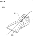
- FIG. 3A is a perspective view of a vehicle camera according to an implementation.
- FIG. 3B is an exploded perspective view of the vehicle camera according to an implementation.
- FIG. 3C is a cross-sectional view of the vehicle camera according to an implementation, taken along line A-B of FIG. 3A .
- the shape of the light shield 230 may be varied according to vehicle model.
- the light shield 230 may have a shape corresponding to the model of the vehicle to which the vehicle camera 200a is attached since the curvature of the windshield and the angle between the windshield and the ground depend on the vehicle model.
- the light shield 230 may be configured to be attachable to/detachable from the vehicle camera 200a.
- the heat-radiating member 240 may be one of a thermal pad and thermal grease.
- the first and second housings 252 and 253 may be made of a plastic material.
- the third housing 253 may be formed to surround the processing board 220.
- the third housing 253 may be provided behind or under the processing board 220.
- the third housing 253 may be formed of a thermally conductive material.
- the third housing 253 may be made of a metal such as aluminum.
- efficient heat radiation may be achieved.
- the heat-radiating part 291 may emit heat generated by the vehicle camera 200a.
- the heat-radiating part 291 may be arranged between the processing board 220 and the third housing 253.
- the heat-radiating part 291 may emit heat generated from the processing board 220 by contacting the processing board 220 and the third housing 253.
- FIG. 3D is a perspective view of a vehicle camera according to an implementation.
- FIG. 3E is an exploded perspective view of the vehicle camera according to an implementation.
- FIG. 3F is a cross-sectional view of the vehicle camera according to an implementation, taken along line C-D of FIG. 3D .
- the housing may include a first lens housing 217a, a second lens housing 217b, a first housing 251a, a second housing 252a and a third housing 253a.
- the interface may perform data communication with the controller 170, the display 141, the sensing unit 125 and the vehicle-driving unit 150 of the vehicle through a wired or wireless communication scheme.
- the sensor information may include at least one of vehicle direction information, vehicle position information (GPS information), vehicle heading information, vehicle speed information, vehicle steering information, vehicle acceleration information, vehicle inclination information, information on forward/reverse movement of the vehicle, battery information, fuel information, tire information, vehicle lamp information (e.g. turn signal information), vehicle internal temperature information, vehicle internal humidity information and information about rainfall.
- GPS information vehicle position information
- vehicle heading information vehicle speed information
- vehicle steering information vehicle acceleration information
- vehicle inclination information information on forward/reverse movement of the vehicle
- battery information fuel information
- tire information e.g. turn signal information
- vehicle lamp information e.g. turn signal information
- vehicle internal temperature information e.g. turn signal information
- vehicle internal humidity information e.g. rainfall
- the interface 430 may communicate with the brake driver 153 for controlling a brake apparatus.
- the interface 430 may provide a signal generated in the processor 470 to the brake driver 153.
- the interface 430 may communicate with the steering driver 152 for controlling a steering apparatus.
- the interface 430 may provide a signal generated in the processor 470 to the steering driver 152.
- the memory 440 may be a storage device such as a ROM, a RAM, an EEPROM, a flash drive and a hard drive. According to one implementation, the memory 440 may be included in the processor 470 as a component thereof.
- the processor 470 may obtain position information of the vehicle.
- the processor 470 may provide a signal for steering or a signal for one-sided braking based on the position information.
- the position information may correspond to a degree of swerving of vehicle direction from a lane in which the vehicle travels.
- the processor 470 may calculate the distance based on the position of the object on the road surface in the image.
- the processor 470 may calculate the distance by counting the number of pixels occupied by the road surface.
- the processor 470 may acquire information about time to collision (TTC) with an object located within the lane in which the vehicle 100 travels.
- TTC time to collision
- the processor 470 may provide a signal for steering to the steering apparatus 152a through the interface 430 based on the TTC with the object.
- the processor 470 may provide a signal for one-sided braking to the brake apparatus 153a through the interface 430 based on the TTC with the object.
- the processor 470 may receive information about air pressure of each tire included in the vehicle 100 from the TPMS 300 through the interface 430.
- the first wheel and the second wheel may be provided different shafts.
- the first wheel and the second wheel may be a front left wheel and a rear left wheel, respectively.
- the first wheel and the second wheel may be a front right wheel and a rear right wheel, respectively.
- the processor 470 may provide a signal for one-sided braking to the brake apparatus 153a through the interface 430 based on the information about the curve.
- the processor 470 may provide a signal for one-sided braking to the brake apparatus 153a through the interface 430 based on the information about the curvature of the curve.
- the processor 470 may provide a signal for steering to the steering apparatus 152a when the curvature of the curve exceeds a predetermined curvature.
- the processor 470 may provide a signal for one-sided braking to the brake apparatus 153a when the curvature of the curve exceeds the predetermined curvature.
- the processor 470 may provide the signal for steering and the signal for one-sided braking together.
- the processor 470 provides the signal for steering and the signal for one-sided braking together such that the vehicle 100 may travel within the lane.
- the processor 470 may provide a signal for steering to the steering apparatus 152a.
- the processor 470 may stop provision of the signal for steering to the steering apparatus 152a.
- the processor 470 may stop provision of the signal for one-sided braking to the brake apparatus 153a.
- the processor 470 may include an image processor 471, a determination unit 474 and a signal supply unit 477.
- the image processor 471 may process the received image using various methods.
- the image processor 471 may calculate a distance between the vehicle and the object based on the image.
- the image processor 471 may calculate the distance between the vehicle and the object based on the focal distance of the lens 211 and the distance between the lens 211 and the image sensor 214.
- the image processor 471 may detect the distance to the object according to disparity calculation in a stereo image.
- the determination unit 474 may receive position information of the vehicle from the sensing unit 125 through the interface 430.
- the determination unit 474 may select steering control or one-sided braking control based on speed information.
- the determination unit 474 may select steering control when the speed of the vehicle 100 exceeds a reference speed.
- the determination unit 474 may select one-sided braking control when the speed of the vehicle 100 is lower than the reference speed.
- the mobile terminal of the user and the driver assistance apparatus 400 may be paired automatically or according to execution of an application by the user.
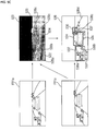
- a segmentation unit 503 may perform segmentation and clustering on at least one image based on the disparity information from the disparity calculator 502.
- the object detector 504 may detect an object from at least one image.
- the object detector 504 may detect an object from a foreground separated according to image segmentation.
- An object verification unit 505 may classify and verify the detected object.
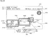
- FIG. 5F illustrates display of information based on an image captured by the stereo camera 200, distinguished from FIG. 5E .
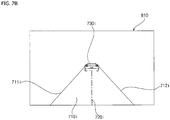
- the processor 470 may detect a lane 710i from an image 810.
- the processor 470 may detect a left line 711i and a right line 712i forming the lane 710i from the image 810.
- the processor may control the vehicle 100 to stop within the lane 710 during braking of the vehicle 100.
- the processor 470 may provide a signal for steering to the steering apparatus 152a or provide a signal for one-sided braking to the brake apparatus 153a such that the vehicle 100 stops within the lane 710 during braking of the vehicle 100.
- FIG. 9B is a front view image of the vehicle, photographed through the vehicle camera, in the situation of FIG. 9A according to an implementation.
- the processor 470 may recognize that the vehicle 100 swerves to the right.
- the processor 470 may detect the position information of the vehicle 100 based on the position of the left line 711i or the right line 712i detected from the image 810.
- the processor 470 may recognize that the vehicle 100 swerves to the right.
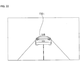
- the processor 470 may detect the position information of the vehicle 100 based on the virtual centerline 720i.
- the processor 470 may recognize that the vehicle 100 swerve to the right.
- the steering input apparatus 1000 may be a steering wheel.
- the steering input apparatus 1000 may include a first indicator 1010 and a second indicator 1020.
- the first indicator 1010 may include at least one light emitting element and the second indicator 1020 may include at least one light emitting element.
- the steering driver 152 may control the steering apparatus 152a.
- the steering apparatus 152a may rotate steering wheels (e.g. front wheels) around the shaft formed in the overall length direction under the control of the steering driver 152.
- the processor 470 may provide a signal for steering to the steering apparatus 152a via the steering driver 152.
- the processor 470 may provide a steering indication signal to the steering input apparatus 1000.
- the processor 470 may provide a signal to the steering input apparatus 1000 such that the light emitting element of the first indicator 1010 emits light when the vehicle needs to be steered to the left and provide a signal to the steering input apparatus 1000 such that the light emitting element of the second indicator 1010 emits light when the vehicle needs to be steered to the right.
- FIG. 11 illustrates a brake system of the vehicle according to an implementation.
- the brake system may include a brake input apparatus 1100, the brake driver 153 and the brake apparatus 153a.
- the brake input apparatus 1100 receives user input for speed reduction of the vehicle 100.
- the brake input apparatus 1100 may be configured in the form of a pedal.
- the brake driver 153 may independently control the first to fourth wheel brakes 1115, 1125, 1135 and 1145.
- the brake driver 153 may control different braking powers to be respectively applied to the first to fourth wheel brakes 1115, 1125, 1135 and 1145.
- FIG. 12 is a flowchart illustrating operation of the driver assistance apparatus according to an implementation.
- the operation of the driver assistance apparatus shown in FIG. 12 may be an exemplary operation of the driver assistance apparatus shown in FIG. 6 .
- the processor 470 may acquire position information of the vehicle (S635).
- the position information may refer to a degree of swerving of the vehicle from the lane in which the vehicle travels.
- the processor 470 may provide a signal for one-sided braking to the brake apparatus 153a when the degree of swerving exceeds the reference value (S1230).
- the processor 470 may provide a signal for one-sided braking to the brake apparatus 153a such that higher braking power is applied to the left wheels than the right wheels when the vehicle 100 swerves to the right on the basis of the forward direction.
- the processor 470 may provide a signal for steering to the steering apparatus 152a when the degree of swerving is less than the reference value (S12240).
- the processor 470 may provide a signal for steering to the steering apparatus 152a such that the vehicle is steered to the left when the vehicle 100 swerves to the right based on the forward direction.
- Steps S1230 and S1240 may be included in step S650 of FIG. 6 .
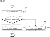
- the operation of the driver assistance apparatus shown in FIG. 14 may be an exemplary operation of the driver assistance apparatus shown in FIG. 6 .
- the processor 470 may provide a signal for steering to the steering apparatus 152a such that the vehicle 100 is steered to the left based on the forward direction when the vehicle 100 swerves to the right.
- the operation of the driver assistance apparatus shown in FIG. 17 may be an exemplary operation of the driver assistance apparatus shown in FIG. 6 .
- the processor 470 may provide a signal for steering to the steering apparatus 152a.
- the processor 470 may provide a signal for steering to the steering apparatus 152a such that the vehicle is steered to the right when the vehicle 100 swerves to the left.
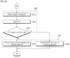
- the processor 470 may acquire information about an object (S2010).
- the object may be a preceding vehicle traveling in the lane in which the vehicle 100 travels.
- the processor 470 may provide a signal for one-sided braking to the brake apparatus 153a.
- the processor 470 may provide a signal for one-sided braking to the brake apparatus 153a such that higher braking power is applied to the left wheels than the right wheels when the vehicle 100 swerves to the right.
- the processor 470 may provide a signal for steering to the steering apparatus 152a.
- the processor 470 may provide a signal for steering to the steering apparatus 152a such that the vehicle is steered to the right when the vehicle 100 swerves to the left.
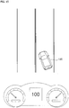
- the processor 470 may provide a signal for one-sided braking to the brake apparatus 153a such that braking power applied to the first wheel is lower than braking power applied to the second wheel.
- the processor 470 may provide a signal for one-sided braking to the brake apparatus 153a such that braking power applied to the second wheel is higher than braking power applied to the first wheel.
- the processor 470 may provide a signal for steering to the steering apparatus 152a such that the vehicle is steered toward the second wheel from the center of the overall length. Referring to FIG. 23 , the processor 470 may provide a signal for steering to the steering apparatus 152a such that the vehicle 100 is steered to the right of the traveling direction.
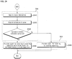
- the operation of the driver assistance apparatus shown in FIG. 24 may be an exemplary operation of the driver assistance apparatus shown in FIG. 6 .
- the processor 470 may acquire information about a curve in front of the vehicle 100 in the lane (S2410).
- the processor 470 may determine whether the curvature of the curve exceeds a reference curvature (S2430).
- Steps S2410, S2420 and S2430 may be included in step S640 of FIG. 6 and steps S2440 and S2450 may be included in step S650 of FIG. 6 .
Abstract
Description
- Pursuant to 35 U.S.C. § 119(a), this application claims an earlier filing date and right of priority to Korean Patent Application No.
10-2016-0042970, filed on April 7, 2016 - The present disclosure relates to an apparatus included in a vehicle, and a vehicle including the same.
- A vehicle is a machine moved by a user who rides therein. An example of a vehicle is a car. For convenience of vehicle users, some vehicles include sensors and electronic devices. For example, some vehicles may include an advanced driver assistance system (ADAS) that provides driver convenience functions. Furthermore, autonomous vehicles are under development that perform some operations of a vehicle without a user's active control.
- Systems and techniques are disclosed herein that enable a driver assistance apparatus to, during a braking operation of a vehicle, maintain the vehicle within a lane in which the vehicle is travelling.
- In the one aspect, a driver assistance apparatus for a vehicle may include a camera configured to photograph an image of surroundings of a vehicle; an interface; and a processor. The processor may be configured to detect, based on the image photographed by the camera, a lane in which the vehicle travels; acquire braking state information of the vehicle; and provide, to a steering apparatus, a signal for steering the vehicle or provide, to a brake apparatus, a signal for one-sided braking through the interface to maintain the vehicle within the lane in which the vehicle travels during a braking of the vehicle based on the acquired braking state information.
- In some implementations, the processor may be configured to acquire the braking state information based on the image of the surroundings of the vehicle or based on receiving the braking state information through the interface.
- In some implementations, the processor may be further configured to determine a degree of swerving of the vehicle from the lane in which the vehicle travels; acquire position information of the vehicle, the position information corresponding to the degree of swerving of the vehicle from the lane in which the vehicle travels; and provide the signal for steering or the signal for one-sided braking based on the acquired position information of the vehicle.
- In some implementations, the processor may be configured to calculate the position information of the vehicle by determining an angle between the left line or the right line of the lane in which the vehicle travels; determining a heading of the vehicle; and calculating the position information of the vehicle based on the angle between the heading of the vehicle and the left line or the right line of the lane in which the vehicle travels.
- In some implementations, the processor may be further configured to determine a virtual centerline of the lane in which the vehicle travels; determine a line corresponding to a center of the width of the vehicle; determine an angle between the virtual centerline of the lane in which the vehicle travels and a line corresponding to a center of a width of the vehicle; and calculate the position information of the vehicle based on the angle between the virtual centerline of the lane in which the vehicle travels and the line corresponding to the center of the width of the vehicle.
- In some implementations, the processor may be configured to determine whether the degree of swerving of the vehicle from the lane in which the vehicle travels is less than a threshold value; and based on a determination that the degree of swerving of the vehicle from the lane in which the vehicle travels is less than the threshold value, provide the signal for one-sided braking to the brake apparatus.
- In some implementations, the processor may be configured to determine whether the degree of swerving of the vehicle from the lane in which the vehicle travels exceeds a threshold value; and based on a determination that the degree of swerving of the vehicle from the lane in which the vehicle travels exceeds the threshold value, provide the signal for steering to the steering apparatus.
- In some implementations, the processor may be further configured to acquire information about a speed of the vehicle; and provide the signal for steering to the steering apparatus or provide the signal for one-sided braking to the brake apparatus based on the acquired speed information.
- In some implementations, the processor may be configured to provide the signal for steering to the steering apparatus based on a determination that the speed of the vehicle exceeds a threshold speed; and provide the signal for one-sided braking to the brake apparatus based on a determination that the speed of the vehicle is less than the threshold speed.
- In some implementations, the processor may be further configured to acquire distance information regarding a distance between the vehicle and an object ahead of the vehicle that is located within the lane in which the vehicle travels; and provide the signal for steering to the steering apparatus or provide the signal for one-sided braking to the brake apparatus based on the acquired distance information.
- In some implementations, the processor may be configured to provide the signal for one-sided braking to the brake apparatus based on a determination that the distance between the vehicle and the object ahead of the vehicle exceeds a threshold distance; and provide the signal for steering to the steering apparatus based on a determination that the distance between the vehicle and the object ahead of the vehicle is less than the threshold distance.
- In some implementations, the processor may be further configured to acquire information regarding a time to collision (TTC) with an object ahead of the vehicle that is located within the lane in which the vehicle travels; and provide the signal for steering to the steering apparatus or provide the signal for one-sided braking to the brake apparatus based on the acquired information regarding the TTC.
- In some implementations, the processor may be further configured to provide the signal for one-sided braking to the brake apparatus based on a determination that the TTC exceeds the threshold time; and provide the signal for steering to the steering apparatus based on a determination that the TTC is less than the threshold time.
- In some implementations, the processor may be further configured to receive, from a tire pressure monitoring system (TPMS) and through the interface, tire pressure information of the vehicle; and provide the signal for one-sided braking to the brake apparatus based on the received tire pressure information of the vehicle.
- In some implementations, the processor may be further configured to determine whether an air pressure of a first tire on a first wheel of the vehicle is less than an air pressure of a second tire on a second wheel of the vehicle; and based on a determination that the air pressure of the first tire on the first wheel of the vehicle is less than the air pressure of the second tire on the second wheel of the vehicle, provide the signal for one-sided braking to the brake apparatus such that a braking power applied to the first wheel of the vehicle is less than a braking power applied to the second wheel of the vehicle.
- In some implementations, the processor may be further configured to acquire information regarding a curve of the lane in which the vehicle travels; and provide the signal for steering to the steering apparatus or provide the signal for one-sided braking to the brake apparatus based on the acquired information regarding the curve of the lane in which the vehicle travels.
- In some implementations, the processor may be further configured to acquire information regarding a curvature of the curve of the lane in which the vehicle travels; determine whether the curvature of the curve exceeds a threshold curvature; and based on a determination that the curvature of the curve exceeds the threshold curvature, provide both the signal for steering to the steering apparatus and the signal for one-sided braking to the brake apparatus.
- In some implementations, the processor may be further configured to acquire information regarding a curvature of the curve of the lane in which the vehicle travels; determine whether the curvature of the curve is less than a threshold curvature; and based on a determination that the curvature of the curve is less than the threshold curvature, provide the signal for steering to the steering apparatus.
- In some implementations, the processor may be further configured to determine a virtual centerline of the lane in which the vehicle travels; and provide the signal for steering to the steering apparatus or the signal for one-sided braking to the brake apparatus such that a center of a width of the vehicle corresponds to the virtual centerline of the lane in which the vehicle travels.
- In some implementations, the processor may be further configured to determine whether a driver intervention event has occurred; and based on a determination that the driver intervention event has occurred, stop a supply of the signal for steering to the steering apparatus or stop a supply of the signal for one-sided braking to the brake apparatus.
-
-
FIG. 1 is a diagram illustrating an example of an exterior of a vehicle according to an implementation; -
FIG. 2 is a block diagram of an example of a vehicle according to an implementation; -
FIG. 3A is a diagram illustrating a perspective view of an example of a vehicle camera according to an implementation; -
FIG. 3B is a diagram illustrating an exploded perspective view of an example of a vehicle camera according to an implementation; -
FIG. 3C is a diagram illustrating a cross-sectional view of an example of a vehicle camera according to an implementation, taken along line A-B ofFIG. 3A ; -
FIG. 3D is a diagram illustrating a perspective view of an example of a vehicle camera according to an implementation; -
FIG. 3E is a diagram illustrating an exploded perspective view of a vehicle camera according to an implementation; -
FIG. 3F is a diagram illustrating a cross-sectional view of an example of a vehicle camera according to an implementation, taken along line C-D ofFIG. 3D ; -
FIG. 4A is a block diagram of an example of a driver assistance apparatus according to an implementation; -
FIG. 4B is a diagram illustrating an example of a processor and signal processing of components of the driver assistance apparatus according to an implementation; -
FIGS. 5A and5B are diagrams illustrating examples of an image processor ofFIG. 4B ; -
FIGS. 5C and5D are diagrams illustrating examples of operations of the processor shown inFIGS. 5A and5B ; -
FIGS. 5E and5F are diagrams illustrating examples of operations of the driver assistance apparatus shown inFIGS. 5A to 5C ; -
FIG. 6 is a flowchart illustrating an example of operations of a driver assistance apparatus according to an implementation; -
FIG. 7A is a diagram illustrating a bird's eye view of an example of a vehicle according to an implementation; -
FIG. 7B is a diagram illustrating a front view image of an example of a vehicle, photographed through a vehicle camera, in the situation ofFIG. 7A according to an implementation; -
FIG. 8A is a diagram illustrating an example of a situation in which a vehicle swerves to the left during braking according to an implementation; -
FIG. 8B is a diagram illustrating a front view image of an example of a vehicle, photographed through a vehicle camera, in the situation ofFIG. 8A according to an implementation; -
FIG. 9A is a diagram illustrating an example of a situation in which a vehicle swerves to the right during braking according to an implementation; -
FIG. 9B is a diagram illustrating a front view image of an example of a vehicle, photographed through a vehicle camera, in the situation ofFIG. 9A according to an implementation; -
FIG. 10 is a diagram illustrating an example of a vehicle steering system according to an implementation; -
FIG. 11 is a diagram illustrating an example of a vehicle brake system according to an implementation; -
FIG. 12 is a flowchart illustrating an example of operations of a driver assistance apparatus according to an implementation; -
FIG. 13 is a diagram illustrating an example of operations of the driver assistance apparatus shown inFIG. 12 according to an implementation; -
FIG. 14 is a flowchart illustrating an example of operations of a driver assistance apparatus according to an implementation; -
FIGS. 15 and16 are diagrams illustrating examples of operations of the driver assistance apparatus shown inFIG. 14 according to an implementation; -
FIG. 17 is a flowchart illustrating an example of operations of a driver assistance apparatus according to an implementation; -
FIGS. 18 and19 are diagrams illustrating examples of operations of the driver assistance apparatus shown inFIG. 17 according to an implementation; -
FIG. 20 is a flowchart illustrating an example of operations of a driver assistance apparatus according to an implementation; -
FIGS. 21 and22 are diagrams illustrating examples of operations of the driver assistance apparatus shown inFIG. 20 according to an implementation; -
FIG. 23 is a diagram illustrating an example of operations of a driver assistance apparatus based on tire pressure according to an implementation; -
FIG. 24 is a flowchart illustrating an example of operations of a driver assistance apparatus according to an implementation; -
FIGS. 25 and26 are diagrams illustrating examples of operations of the driver assistance apparatus shown inFIG. 24 . - In the event of a sudden braking operation of a vehicle, the vehicle's direction of motion may unexpectedly change despite a user's steering input not having been applied to the vehicle. When the vehicle deviates from a lane due to an unexpected change of direction of the vehicle, an accident may be more likely to occur.
- A driver assistance apparatus is described herein that, during a braking operation of a vehicle, automatically maintains the vehicle within a lane in which the vehicle is travelling.
- Such a driver assistance apparatus may have one or more of the following advantages.
- Firstly, a vehicle may be controlled to come to a stop within the lane in which the vehicle travels by applying one-sided braking and steering control according to a situation during the braking operation. One-sided braking may include controlling the vehicle's brakes such that that braking power is applied differently to different wheels of the vehicle.
- Secondly, accidents occurring when a vehicle deviates from a lane in which the vehicle travels may be prevented.
- Thirdly, one-sided braking control may be performed when the vehicle considerably deviates from the lane to prevent injury to the driver caused by steering wheel rotation according to sudden steering.
- Fourthly, position stability of a vehicle may be achieved by appropriately using one-sided braking control and steering control based on factors such as the speed of the vehicle, a distance between the vehicle and an object, time to collision (TTC), tire pressure, and driving around a curve.
- Effects of a driver assistance apparatus disclosed herein are not limited to the above-described effects and other effects which are not described herein will become apparent to those skilled in the art from the following description.
- A vehicle described in the specification may include a car and a motorcycle. The car is described as the vehicle in the following.
- The vehicle described in the specification may include an internal combustion engine vehicle having an engine as a power source, a hybrid vehicle having an engine and an electric motor as a power source, an electric vehicle having an electric motor as a power source, or any suitable source of power.
- In the following description, the left side of a vehicle refers to the left side of a driving direction of the vehicle and the right side of the vehicle refers to the right side of the driving direction of the vehicle.
-
FIG. 1 shows the exterior of avehicle 100 according to an implementation. - As shown, the
vehicle 100 may include wheels rotating by a power source and a steering device for steering thevehicle 100. - According to one implementation, the
vehicle 100 may be an autonomous vehicle. An autonomous vehicle may be switched to an autonomous driving mode or a manual mode according to user input. In the manual mode, theautonomous vehicle 100 may receive user input for driving through an operation unit (121 ofFIG. 2 ). - The
vehicle 100 may include adriver assistance apparatus 400. Thedriver assistance apparatus 400 assists the driver of the vehicle based on information acquired through various sensors. Thedriver assistance apparatus 400 may be referred to as an advanced driver assistance system (ADAS). - While a
vehicle camera 200 is described as a sensor used for thedriver assistance apparatus 400 in the following description, implementations are not limited thereto. According to one implementation, a radar, lidar, ultrasonic sensor, infrared sensor and the like may be used as sensors for thedriver assistance apparatus 400 in addition to thevehicle camera 200. - In addition, a
mono camera 200a and astereo camera 200b are described as thecamera 200 for use in thedriver assistance apparatus 400 in the following. However, implementations are not limited thereto. According to one implementation, thevehicle camera 200 may include a triple camera, an around view monitoring (AVM) camera, a 360° camera and an omnidirectional camera. - While
FIG. 1 shows that thevehicle camera 200 used in thedriver assistance apparatus 400 is provided to a windshield of the vehicle such that thevehicle camera 200 may capture a front view image of thevehicle 100, thevehicle camera 200 may capture a front view image, a rear view image, a right side image and a left side image of the vehicle. Accordingly, thevehicle camera 200 may be provided to an appropriate position outside or inside the vehicle. - The overall length refers to the length between the front part and the rear part of the
vehicle 100, width refers to the width of thevehicle 100 and height refers to the distance between the lower part of the wheel and the roof of thevehicle 100. In the following description, an overall length direction L may refer to a direction in which the overall length of thevehicle 100 is measured, a width direction W may refer to a direction in which the width of thevehicle 100 is measured, and a height direction H may refer to a direction in which the height of thevehicle 100 is measured. -
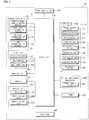
FIG. 2 is a block diagram of the vehicle according to an implementation. - Referring to
FIG. 2 , thevehicle 100 may include acommunication unit 110, aninput unit 120, asensing unit 125, amemory 130, anoutput unit 140, avehicle driving unit 150, acontroller 170, aninterface 180, apower supply unit 190, a tire pressure monitoring system (TPMS) 300 and thedriver assistance apparatus 400. - The
communication unit 110 may include a short-range communication module 113, aposition information module 114, anoptical communication module 115 and aV2X communication module 116. - The
communication unit 110 may include one or more radio frequency (RF) circuits or devices for communication with other devices. - The short-
range communication module 113 is a module for short range communication and may support short range communication using at least one of Bluetooth™, RFID (Radio Frequency Identification), Infrared Data Association (IrDA), UWB (Ultra-Wideband), ZigBee, NFC (Near Field Communication), Wi-Fi (Wireless-Fidelity), Wi-Fi Direct and Wireless USB (Wireless Universal Serial Bus). - The short-
range communication module 113 may perform short-range communication between thevehicle 100 and at least one external device by establishing wireless area networks. For example, the short-range communication module 113 may wirelessly exchange data with a mobile terminal. The short-range communication module 113 may receive weather information and traffic information (e.g., transport protocol experts group (TPEG) information) from a mobile terminal. When a user enters thevehicle 100, a mobile terminal of the user and thevehicle 100 may be paired automatically or according to execution of an application by the user. - The
position information module 114 is a module for locating thevehicle 100 and a typical example thereof is a GPS (Global Positioning System) module. For example, the vehicle may acquire the location thereof using signals sent from a GPS satellite using the GPS module. - According to one implementation, the
position information module 114 may be a component included in thesensing unit 125 instead of thecommunication unit 110. - The
optical communication module 115 may include a light transmission unit and a light receiving unit. - The light receiving unit converts a light signal into an electrical signal so as to receive information. The light receiving unit may include a photodiode (PD) for receiving light. The photodiode converts light into an electrical signal. For example, the light receiving unit may receive information on a preceding vehicle through light emitted from a light source included in the preceding vehicle.
- The light transmission unit may include at least one light-emitting element for converting an electrical signal into a light signal. Here, the light-emitting element may be an LED (Light Emitting Diode). The light transmission unit converts an electrical signal into a light signal and emits the light signal. For example, the light transmission unit may emit a light signal through flickering of the light-emitting element, which corresponds to a predetermined frequency. According to one implementation, the light transmission unit may include a plurality of light-emitting element arrays. According to one implementation, the light transmission unit may be integrated with a lamp provided to the
vehicle 100. For example, the light transmission unit may be at least one of a headlight, a taillight, a brake light, a turn signal lamp and a sidelight. For example, theoptical transmission module 115 may exchange data with another vehicle through optical communication. - The
V2X communication module 116 is a module for wireless communication between thevehicle 100 and a server or other vehicles. TheV2X communication module 116 includes a module in which a vehicle-to-vehicle communication (V2V) or vehicle-to-infrastructure communication (V2I) protocol may be implemented. Thevehicle 100 may perform wireless communication with an external server or other vehicles through theV2X communication module 116. - The
input unit 120 may include anoperation unit 121, amicrophone 123 and auser input unit 124. - The
operation unit 121 receives user input for driving thevehicle 100. Theoperation unit 121 may include a steering input unit, a shift input unit, an acceleration input unit and a brake input unit. - The user applies steering input to the steering input unit. The steering input unit may be configured as a steering wheel such that steering input according to rotation may be applied. According to one implementation, the steering input unit may be configured in the form of a touchscreen, a touch pad or a button.
- The user applies inputs with respect to park (P), drive (D), neutral (N), and reverse (R) of the
vehicle 100 through the shift input unit. The shift input unit may be configured in the form of a lever. According to one implementation, the shift input unit may be configured in the form of a touchscreen, a touch pad or a button. - The user applies input with respect to acceleration of the
vehicle 100 through the acceleration input unit. The user applies input with respect to reduction of the speed of thevehicle 100 to the brake input unit. The acceleration input unit and the brake input unit may be configured in the form of a pedal. According to one implementation, the acceleration input unit or the brake input unit may be configured in the form of a touchscreen, a touch pad or a button. - The
microphone 123 may process an external audio signal into electrical data. The processed data may be used in various manners according to functions executed in thevehicle 100. Themicrophone 123 may convert a voice command of the user into electrical data. The converted electrical data may be transmitted to thecontroller 170. - According to one implementation, the camera 122 or the
microphone 123 may be included in thesensing unit 125 instead of theinput unit 120. - The
user input unit 124 is used to receive information from the user. Upon input of information through theuser input unit 124, thecontroller 170 may control operation of thevehicle 100 to respond to the input information. Theuser input unit 124 may include a touch type input unit or a mechanical input unit. According to one implementation, theuser input unit 124 may be provided to a region of the steering wheel of the vehicle. In this case, the driver may operate theuser input unit 124 with a finger while gripping the steering wheel. - The
sensing unit 125 senses states of thevehicle 100 or external states of thevehicle 100. To this end, thesensing unit 125 may include a collision sensor, a wheel sensor, a speed sensor, a tilt sensor, a weight sensor, a heading sensor, a yaw sensor, a gyro sensor, a position module, a front side/rear side sensor, a battery sensor, a fuel sensor, a tire sensor, a steering sensor, a vehicle internal temperature sensor, a vehicle internal humidity sensor, an ultrasonic sensor, an illumination sensor, an acceleration pedal position sensor, a brake pedal position sensor and the like. - Accordingly, the
sensing unit 125 may acquire sensing signals with respect to vehicle collision information, vehicle direction information, vehicle position information (GPS information), heading information, speed information, acceleration information, vehicle inclination information, driving/reverse information, battery information, fuel information, tire information, vehicle lamp information, vehicle internal temperature information, vehicle internal humidity information, steering wheel rotation angle information, external illumination, pressure applied to the acceleration pedal, pressure applied to the brake pedal and the like. - In addition, the
sensing unit 125 may further include an acceleration pedal sensor, a pressure sensor, an engine speed sensor, an air flow sensor (AFS), an air temperature sensor (ATS), a water temperature sensor (WTS), a throttle position sensor (TPS), a TDC sensor, a crank angle sensor (CAS) and the like. - The
position information module 114 may be classified as a component of thesensing unit 125. - The
sensing unit 125 may include an object sensor for sensing an object around the vehicle. The object sensor may include a camera module, a radar, a lidar and an ultrasonic sensor. In this case, thesensing unit 125 may sense an object in front of the vehicle or an object behind the vehicle through the camera module, radar, lidar or ultrasonic sensor. - According to one implementation, the object sensor may be classified as a component of the
driver assistance apparatus 400. - The
memory 130 is electrically connected to thecontroller 170. Thememory 130 may store fundamental data about the units, control data for operation control of the units and input/output data. Thememory 130 may be various types of storage devices such as a ROM, a RAM, an EPROM, a flash drive and a hard drive. Thememory 130 may store various types of data for the overall operation of thevehicle 100, such as programs for processing or control. - The
output unit 140 outputs information processed by thecontroller 170 and may include adisplay 141, anaudio output unit 142 and ahaptic output unit 143. - The
display 141 may display various graphical objects. For example, thedisplay 141 may display vehicle related information. The vehicle related information may include vehicle control information for direct control of the vehicle or vehicle driving assistance information for providing driving guidance to the vehicle driver. In addition, the vehicle related information may include vehicle state information indicating the current state of the vehicle or vehicle driving information related to driving of the vehicle. - The
display 141 may include at least one of a liquid crystal display (LCD), a thin film transistor-liquid crystal display (TFT LCD), an organic light emitting diode (OLED), a flexible display, a 3D display and an e-ink display. - The
display 141 may implement a touchscreen by forming a layered structure with a touch sensor or by being integrated with the touch sensor. Such touchscreen may function as the user input unit that provides an input interface between thevehicle 100 and the user and, simultaneously, provide an output interface between thevehicle 100 and the user. In this case, thedisplay 141 may include a touch sensor for sensing touch applied to thedisplay 141 such that a control command is input to thedisplay 141 through touch. When touch is applied to thedisplay 141, the touch sensor may sense the touch and thecontroller 170 may generate a control command corresponding to the touch based on the sensed touch. Input applied through touch may be text, figures or menu items that may be indicated or designated in various modes. - The
display 141 may include a cluster to enable the driver to drive the vehicle and, simultaneously, to check vehicle state information or vehicle driving information. The cluster may be provided on the dashboard. In this case, the driver may check information displayed on the cluster while looking forward. - According to one implementation, the
display 141 may be implemented as an HUD (Head Up Display). When thedisplay 141 is implemented as an HUD, information may be output through a transparent display provided to the windshield of the vehicle. Alternatively, thedisplay 141 may include a projection module so as to output information through an image projected to the windshield. - According to one implementation, the
display 141 may include a transparent display. In this case, the transparent display may be attached to the windshield. - The transparent display may display a predetermined screen with predetermined transparency. For transparency, the transparent display may include at least one of a transparent TFEL (Thin Film Electroluminescent) display, a transparent OLED (Organic Light-Emitting Diode) display, a transparent LCD (Liquid Crystal Display), a transmission type transparent display and a transparent LED (Light Emitting Diode) display. The transparency of the transparent display may be controlled.
- According to one implementation, the
display 141 may function as a navigation system. - The
audio output unit 142 converts an electrical signal from thecontroller 170 into an audio signal and outputs the audio signal. To this end, theaudio output unit 142 may include a speaker. Theaudio output unit 142 may output sound corresponding to operation of theuser input unit 124. - The
haptic output unit 143 generates haptic output. For example, thehaptic output unit 143 may vibrate the steering wheel, a safety belt or a seat to enable the user to recognize haptic output. - The vehicle-driving
unit 150 may control operations of various devices of the vehicle. The vehicle-drivingunit 150 may include apower source driver 151, asteering driver 152, abrake driver 153, alamp driver 154, an air-conditioner driver 155, awindow driver 156, anairbag driver 157, asunroof driver 158, and asuspension driver 159. - The
power source driver 151 may perform electronic control of a power source of thevehicle 100. - For example, when the power source is a fossil fuel based engine, the
power source driver 151 may perform electronic control of the engine so as to control the output torque of the engine. When thepower source driver 151 is an engine, the speed of the vehicle may be limited by restricting an engine output torque under the control of thecontroller 170. - Alternatively, when an electric motor is a power source, the
power source driver 151 may control the motor. Accordingly, revolutions per minute (RPM), torque and the like of the motor may be controlled. - The
steering driver 152 may electronically control a steering apparatus of thevehicle 100 so as to steer thevehicle 100. - The
brake driver 153 may electronically control a brake apparatus of thevehicle 100. For example, thebrake driver 153 may reduce the speed of thevehicle 100 by controlling the operation of a brake provided to the wheels. As another example, thebrake driver 153 may adjust the direction of thevehicle 100 to the left or right by differently operating brakes respectively provided to the left and right wheels. - The
lamp driver 154 may turn on/turn off lamps provided to the inside and outside of thevehicle 100. In addition, thelamp driver 154 may control illuminance, directions and the like of the lamps. For example, thelamp driver 154 may control the turn signal, brake lamp and the like. - The air-
conditioner driver 155 may electronically control an air conditioner of thevehicle 100. For example, the air-conditioner driver 155 may control the air conditioner to supply chilly air to the inside of thevehicle 100 when the internal temperature of the vehicle is high. - The
window driver 156 may electronically control a window apparatus of thevehicle 100. For example, thewindow driver 156 may control opening or closing of left and right windows provided to the side of the vehicle. - The
airbag driver 157 may electronically control an airbag apparatus provided to the inside of thevehicle 100. For example, theairbag driver 157 may control the airbag apparatus to operate in a dangerous situation. - The
sunroof driver 158 may electronically control a sunroof apparatus of thevehicle 100. For example, thesunroof driver 158 may control opening or closing of a sunroof. - The
suspension driver 159 may electronically control a suspension apparatus of thevehicle 100. For example, thesuspension driver 159 may reduce vibration of thevehicle 100 by controlling the suspension apparatus when the surface of the road is rough. - According to one implementation, the vehicle-driving
unit 150 may include a chassis driver. The chassis driver may include thesteering driver 152,brake driver 153 and suspension driver 169. - The
controller 170 may control operations of the respective units of thevehicle 100. Thecontroller 170 may be called an ECU (Electronic Control Unit). - The
controller 170 may be implemented using at least one of ASICs (application specific integrated circuits), DSPs (digital signal processors), DSPDs (digital signal processing devices), PLDs (programmable logic devices), FPGAs (field programmable gate arrays), processors, controllers, microcontrollers, microprocessors and other electrical units for executing the corresponding functions. - The
interface 180 may serve as a passage between thevehicle 100 and various external devices connected to thevehicle 100. For example, theinterface 180 may include a port connectable to a mobile terminal and may be connected to the mobile terminal through the port. In this case, theinterface 180 may exchange data with the mobile terminal. - The
interface 180 may serve as a passage through which electric energy is supplied to the mobile terminal connected thereto. When the mobile terminal is electrically connected to theinterface 180, theinterface 180 may provide electric energy supplied from thepower supply unit 190 to the mobile terminal under the control of thecontroller 170. - The
power supply unit 190 may provide power that is used for operations of the components of thevehicle 100 under the control of thecontroller 170. Thepower supply unit 190 may be provided with power from a battery included in the vehicle. - The
TPMS 300 may sense air pressure of each tire of thevehicle 100. TheTPMS 300 includes an air pressure sensor. The air pressure sensor may sense air pressure inside each tire. TheTPMS 300 may further include a temperature sensor. The temperature sensor may sense the internal temperature of each tire. - The
TPMS 300 may output the air pressure or temperature of each tire. TheTPMS 300 may provide a signal to thedisplay 141 and thedisplay 141 may output the air pressure or temperature of each tire. - The
driver assistance apparatus 400 may assist driving of the vehicle by the driver. Thedriver assistance apparatus 400 may include thevehicle camera 200. - The
vehicle camera 200 may include themono camera 200a shown inFIGS. 3A to 3C and thestereo camera 200b shown inFIGS. 3D to 3F . - The
vehicle camera 200 may be called a vehicle camera device. -
FIG. 3A is a perspective view of a vehicle camera according to an implementation.FIG. 3B is an exploded perspective view of the vehicle camera according to an implementation.FIG. 3C is a cross-sectional view of the vehicle camera according to an implementation, taken along line A-B ofFIG. 3A . - The
vehicle camera 200 described with reference toFIGS. 3A to 3C is asingle camera 200a. - The
vehicle camera 200a may include alens 211, animage sensor 214 and aprocessor 470. - According to one implementation, the
vehicle camera 200a may further include aprocessing board 220, alight shield 230, a heat-radiatingmember 240 and ahousing 250, or a combination thereof. - The
housing 250 may include afirst housing 251, asecond housing 252 and athird housing 253. - The
lens 211 is accommodated in alens housing 217 and coupled to thefirst housing 251 by being fitted in ahole 219 formed in a region of thefirst housing 251 through anut 212. - The
image sensor 214 may include at least one photoelectric conversion device for converting an optical signal into an electrical signal. For example, theimage sensor 214 may be a charge-coupled device (CCD) or a complimentary metal-oxide semiconductor (CMOS). - The
image sensor 214 may be provided to an appropriate region outside or inside the vehicle in order to acquire an image of surroundings or inside of the vehicle. - For example, the
image sensor 214 may be disposed in proximity to afront windshield 10 inside the vehicle in order to acquire a front view image of the vehicle. Theimage sensor 214 may be provided around a front bumper or a radiator grille. - For example, the
image sensor 214 may be provided in proximity to a rear windshield inside the vehicle in order to obtain a rear view image of the vehicle. Theimage sensor 214 may be provided around a rear bumper, a trunk or a tailgate. - For example, the
image sensor 214 may be provided in proximity to at least one side window inside the vehicle in order to acquire a side view image of the vehicle. Theimage sensor 214 may be provided around a side mirror, a fender or a door. - The
image sensor 214 may be disposed behind thelens 211 to acquire an image based on light input through thelens 211. For example, theimage sensor 214 may be disposed perpendicular to the ground having a predetermined distance from thelens 211. - The
processor 470 may be electrically connected to theimage sensor 214. Theprocessor 470 may process an image acquired through theimage sensor 214. Theprocessor 470 may control theimage sensor 214. - The
processor 470 may be implemented using at least one of ASICs (application specific integrated circuits), DSPs (digital signal processors), DSPDs (digital signal processing devices), PLDs (programmable logic devices), FPGAs (field programmable gate arrays), processors, controllers, microcontrollers, microprocessors, and other electrical units for executing the corresponding functions. - The
processor 470 may be mounted on theprocessing board 220. - The
processing board 220 may have the processor 270 and amemory 440 mounted thereon. - The
processing board 220 may be inclined in the overall length direction. For example, theprocessing board 220 may be disposed such that the front side or rear side thereof faces thefront windshield 10. For example, theprocessing board 220 may be arranged in parallel with thefront windshield 10. - The
front windshield 10 included in thevehicle 100 is formed at a predetermined angle to the ground from the bonnet to the roof of thevehicle 100. In this case, since theprocessing board 220 is inclined in the overall length direction, thevehicle camera 200a may be smaller than when theprocessing board 220 is disposed vertically or horizontally. Accordingly, a space corresponding to the reduced volume of thevehicle camera 200a in thevehicle 100 may be secured. - The
processing board 220 may have a plurality of elements or electronic components mounted thereon. Here, the plurality of elements or components mounted on theprocessing board 220 may generate heat. - The
processing board 220 may be disposed having a distance from theimage sensor 214 such that heat generated from theprocessing board 220 does not affect the performance of theimage sensor 214. - The
processing board 220 may be disposed at an optimum position such that heat generated from theprocessing board 220 does not affect theimage sensor 214. - Specifically, the
processing board 220 may be provided under theimage sensor 214. Theprocessing board 220 may be provided in front of theimage sensor 214. - One or
more memories 440 may be mounted on theprocessing board 220. Thememory 440 may store images acquired through theimage sensor 214, application data, data for control of theprocessor 470 and data processed by theprocessor 470. Thememory 440 is a heat-generating element like theprocessor 470. Thememory 440 may be provided around theprocessor 470 disposed at the center of theprocessing board 220. For example, one ormore memories 440 may be arranged to surround theprocessor 470. In this case, theprocessor 470 and thememory 440, which are heat-generating elements, may be farthest from theimage sensor 214. - The
processor 470 may be electrically connected to thecontroller 170 such that theprocessor 470 may be controlled by thecontroller 170. - The
light shield 230 may be provided in front of thelens 211. Thelight shield 230 may shield light that is unnecessary to acquire an image such that the light is not input to thelens 211. For example, thelight shield 230 may shield light reflected from thewindshield 10 or the dashboard of the vehicle. In addition, thelight shield 230 may shield unnecessary light. - The
light shield 230 may be configured as a screen. For example, thelight shield 230 may be formed as a bottom screen. - The shape of the
light shield 230 may be varied according to vehicle model. For example, thelight shield 230 may have a shape corresponding to the model of the vehicle to which thevehicle camera 200a is attached since the curvature of the windshield and the angle between the windshield and the ground depend on the vehicle model. To this end, thelight shield 230 may be configured to be attachable to/detachable from thevehicle camera 200a. - The heat-radiating
member 240 may be provided behind theimage sensor 214. The heat-radiatingmember 240 may come into contact with theimage sensor 214 or an image sensor board on which theimage sensor 214 is mounted. The heat-radiatingmember 240 may dissipate heat generated by theimage sensor 214. - As described above, the image sensor 241 is sensitive to heat. The heat-radiating
member 240 may be arranged between theimage sensor 214 and thethird housing 253. The heat-radiatingmember 240 may be disposed such that theimage sensor 214 and thethird housing 253 come into contact with each other. In this case, the heat-radiatingmember 240 may emit heat through thethird housing 253. - For example, the heat-radiating
member 240 may be one of a thermal pad and thermal grease. - The
housing 250 may include thelens housing 217, thefirst housing 251, thesecond housing 252 and thethird housing 253. - The
lens housing 217 may accommodate at least onelens 211 and protect thelens 211 from external impact. - The
first housing 251 may be formed to surround theimage sensor 214. Thefirst housing 251 may include thehole 219. Thelens 211 may be fitted in thehole 219 while being accommodated in the lens housing and connected to theimage sensor 214. - The
first housing 251 may become thicker with decreasing distance to theimage sensor 214. For example, thefirst housing 251 may be formed through die-casting. In this case, the portion of thefirst housing 251, close to theimage sensor 214, may be thicker than other portions in order to prevent performance deterioration of theimage sensor 214 due to heat. - The
first housing 251 may be thicker than thethird housing 253. In the case of a thick housing, heat transfer is slow. Accordingly, when thefirst housing 251 is thicker than thethird housing 253, heat generated inside thevehicle camera 200a is radiated through thethird housing 253 rather than thefirst housing 251 that is disposed in proximity to thefront windshield 10 and thus has difficulty in heat radiation. - In one implementation, the
lens housing 217 and thefirst housing 251 may be integrated. - The
second housing 252 may be provided in front of theprocessing board 220. Thesecond housing 252 may be coupled to thefirst housing 251 and thethird housing 253 through a predetermined coupling. - The
second housing 252 may include an attachment for attaching thelight shield 230 thereto. Thelight shield 230 may be attached to thesecond housing 252 through the attachment. - The first and
second housings - The
third housing 253 may be coupled to thefirst housing 251 and thesecond housing 252 through a predetermined coupling. In an implementation, the first, second andthird housings - The
third housing 253 may be formed to surround theprocessing board 220. Thethird housing 253 may be provided behind or under theprocessing board 220. Thethird housing 253 may be formed of a thermally conductive material. For example, thethird housing 253 may be made of a metal such as aluminum. When thethird housing 253 is made of a thermally conductive material, efficient heat radiation may be achieved. - When the first and
second housings third housing 253 is formed of a thermally conductive material, heat generated inside thevehicle camera 200a may be radiated through thethird housing 253 rather than the first andsecond housings vehicle camera 200a is attached to the windshield, heat may not be emitted through the first andsecond housings second housings third housing 253. - When the
third housing 253 is made of aluminum, thethird housing 253 may protect components (e.g. theimage sensor 214 and the processor 470) included in thevehicle camera 200a from EMC (electromagnetic compatibility) and ESD (electrostatic discharge). - The
third housing 253 may come into contact with theprocessing board 220. In this case, thethird housing 253 may transfer heat through a contact portion between thethird housing 253 and theprocessing board 220 to efficiently emit heat. - The
third housing 253 may further include a heat-radiatingpart 291. For example, the heat-radiatingpart 291 may include at least one of a heat sink, a radiation fin, a thermal pad and thermal grease. - The heat-radiating
part 291 may emit heat generated by thevehicle camera 200a. For example, the heat-radiatingpart 291 may be arranged between theprocessing board 220 and thethird housing 253. The heat-radiatingpart 291 may emit heat generated from theprocessing board 220 by contacting theprocessing board 220 and thethird housing 253. - The
third housing 253 may further include an air hole for emitting hot air inside thevehicle camera 200a to the outside of thevehicle camera 200a. An airflow part connected to the air hole may be included in thevehicle camera 200a. The airflow part may guide hot air inside thevehicle camera 200a to the air hole. - The
vehicle camera 200a may further include a moisture-proof part. The moisture-proof part may take the form of a patch and may be attached to an air exhaust part. The moisture-proof part may be a moisture-proof member made of Gore-Tex. The moisture-proof part may emit moisture inside thevehicle camera 200a to the outside. In addition, the moisture-proof part may prevent external moisture from being introduced into thevehicle camera 200a. -
FIG. 3D is a perspective view of a vehicle camera according to an implementation.FIG. 3E is an exploded perspective view of the vehicle camera according to an implementation.FIG. 3F is a cross-sectional view of the vehicle camera according to an implementation, taken along line C-D ofFIG. 3D . - The
vehicle camera 200 described with reference toFIGS. 3D to 3F is astereo camera 200b. - Description of the
single camera 200a aforementioned with reference toFIGS. 3A to 3C may be equally applied to thestereo camera 200b. That is, each of first and second cameras included in thestereo camera 200b may be the camera described with reference toFIGS. 3A to 3C . - The
stereo camera 200b may include afirst lens 211a, asecond lens 211b, afirst image sensor 214a, asecond image sensor 214b and aprocessor 470a. - In an implementation, the
vehicle camera 200b may further include aprocessing board 220a, afirst light shield 230a, a secondlight shield 230b and ahousing 250a, or a combination thereof. - The housing may include a
first lens housing 217a, asecond lens housing 217b, afirst housing 251a, asecond housing 252a and athird housing 253a. - Description of the
lens 211 with reference toFIGS. 3A to 3C may be applied to thefirst lens 211a and thesecond lens 211b. - Description of the
first image sensor 214a and thesecond image sensor 214b with reference toFIGS. 3A to 3C may be applied to the first andsecond image sensors - A module including the
first lens 211a and thefirst image sensor 214a may be called a first image acquisition module. A module including thesecond lens 211b and thesecond image sensor 214b may be called a second image acquisition module. - The
processor 470a may be electrically connected to thefirst image sensor 214a and thesecond image sensor 214b. Theprocessor 470a may process images acquired through the first andsecond image sensors processor 470a may generate a disparity map or perform disparity calculation on the basis of images acquired through the first andsecond image sensors - The
processor 470a may be implemented using at least one of ASICs (application specific integrated circuits), DSPs (digital signal processors), DSPDs (digital signal processing devices), PLDs (programmable logic devices), FPGAs (field programmable gate arrays), processors, controllers, micro-controllers, microprocessors, and other electrical units for executing the corresponding functions. - The
processor 470 may be mounted on theprocessing board 220a. - Description of the
processing board 220 with reference toFIGS. 3A to 3C may be applied to theprocessing board 220a. - Description of the
light shield 230 with reference toFIGS. 3A to 3C may be applied to thefirst light shield 230a and the secondlight shield 230b. - Description of the
lens housing 217 with reference toFIGS. 3A to 3C may be applied to thefirst lens housing 217a and thesecond lens housing 217b. - Description of the
first housing 251 with reference toFIGS. 3A to 3C may be applied to thefirst housing 251a. - Description of the
second housing 252 with reference toFIGS. 3A to 3C may be applied to thesecond housing 252a. - Description of the
third housing 253 with reference toFIGS. 3A to 3C may be applied to thethird housing 253a. -
FIG. 4A is a block diagram of the driver assistance apparatus according to an implementation. - Referring to
FIG. 4A , thedriver assistance apparatus 400 may include thevehicle camera 200, aprocessor 470, aninterface 430 and amemory 440. - According to one implementation, the
driver assistance apparatus 400 may further include acommunication unit 410, aninput unit 420, anoutput unit 450 and apower supply unit 490, or a combination thereof. - According to one implementation, the
processor 470, theinterface 430 and thememory 440 may be components of thecamera 200. In this case, thevehicle camera device 200 may function as thedriver assistance apparatus 400. - The
vehicle camera 200 is attached to a portion of thevehicle 100 to acquire an image. - For example, the
vehicle camera 200 may be disposed in proximity to thefront windshield 10 inside the vehicle in order to acquire a front view image of the vehicle. Thevehicle camera 200 may be provided around the front bumper or the radiator grille of the vehicle. - For example, the
vehicle camera 200 may be provided in proximity to the rear windshield inside the vehicle in order to obtain a rear view image of the vehicle. Thevehicle camera 200 may be provided around the rear bumper, the trunk or the tailgate. - For example, the
vehicle camera 200 may be provided in proximity to at least one side window inside the vehicle in order to acquire a side view image of the vehicle. Thevehicle camera 200 may be provided around a side mirror, the fender or a door. - The
vehicle camera 200 may include theimage sensor 214 and an actuator 401. - The
image sensor 214 has been described with reference toFIGS. 3A to 3F . - According to one implementation, the
vehicle camera 200 may be a stereo camera (200b ofFIGS. 3D to 3F ). - When the
vehicle camera 200 is thestereo camera 200b, thevehicle camera 200 may include the first camera, the second camera and theprocessor 470. - The
interface 430 may receive signals, information or data. Theinterface 430 may transmit signals, information or data processed or generated in theprocessor 470 to the outside. - To this end, the interface may perform data communication with the
controller 170, thedisplay 141, thesensing unit 125 and the vehicle-drivingunit 150 of the vehicle through a wired or wireless communication scheme. - The
interface 430 may receive information about air pressure of each tire from theTPMS 300. - The
interface 430 may receive sensor information from thecontroller 170 or thesensing unit 125. - Here, the sensor information may include at least one of vehicle direction information, vehicle position information (GPS information), vehicle heading information, vehicle speed information, vehicle steering information, vehicle acceleration information, vehicle inclination information, information on forward/reverse movement of the vehicle, battery information, fuel information, tire information, vehicle lamp information (e.g. turn signal information), vehicle internal temperature information, vehicle internal humidity information and information about rainfall.
- Such sensor information may be acquired from a heading sensor, a yaw sensor, a gyro sensor, a position module, a vehicle front/rear sensor, a wheel sensor, a speed sensor, a steering angle sensor, a car body tilting sensor, a battery sensor, a fuel sensor, a tire sensor, a steering sensor, a vehicle internal temperature sensor, a vehicle internal humidity sensor and a rain sensor. The position module may include a GPS module for receiving GPS information.
- The
interface 430 may receive navigation information through data communication with thecontroller 170, the display 141 a separate navigation system. The navigation information may include information on a set destination, route information depending on the destination, map information related to driving of the vehicle, and information on the current position of the vehicle. In addition, the navigation information may include information on the position of the vehicle on a road. - The
interface 430 may provide a signal to thecontroller 170 or the vehicle-drivingunit 150. Here, the signal may be a control signal. - For example, the
interface 430 may communicate with thepower source driver 151 for controlling a power source. Theinterface 430 may provide a signal generated in theprocessor 470 to thepower source driver 151. - For example, the
interface 430 may communicate with thebrake driver 153 for controlling a brake apparatus. Theinterface 430 may provide a signal generated in theprocessor 470 to thebrake driver 153. - For example, the
interface 430 may communicate with thesteering driver 152 for controlling a steering apparatus. Theinterface 430 may provide a signal generated in theprocessor 470 to thesteering driver 152. - The
memory 440 may store various types of data for overall operation of thedriver assistance apparatus 400, such as a program for processing or control of theprocessor 470. - The
memory 440 may be a storage device such as a ROM, a RAM, an EEPROM, a flash drive and a hard drive. According to one implementation, thememory 440 may be included in theprocessor 470 as a component thereof. - The
processor 470 may be electrically connected to each unit of thedriver assistance apparatus 400. - The
processor 470 may control overall operation of each unit of thedriver assistance apparatus 400. - The
processor 470 may receive an image of surroundings of the vehicle, captured by thevehicle camera 200. Theprocessor 470 may detect a lane from the received image. - The
processor 470 may acquire information about a braking state of thevehicle 100. - The
processor 470 may acquire braking state information of thevehicle 100 based on the received image. For example, theprocessor 470 may obtain braking state information of thevehicle 100 based on whether relative speed of the vehicle with respect to a fixed object (e.g. a tree, streetlight, traffic sign or traffic lamp) decreases. - The
processor 470 may receive braking state information of thevehicle 100 from theoperation unit 121, thebrake driver 153, abrake apparatus 153a or thecontroller 170 through theinterface 430. - The braking state information may be full braking state information. Alternatively, the braking state information may be information about braking state corresponding to 80% or higher of full braking. Alternatively, the braking state information may be information about braking state corresponding to 80% to 100% of full braking.
- In a braking state of the
vehicle 100, straightness of braking may be lost due to one-sided wear of each tire, air pressure deviation of each tire, a road state, a brake pad state and the like. In this case, thevehicle 100 may be controlled to be braked within a lane in which thevehicle 100 travels through steering control or one-sided braking control to prevent accidents. - The
processor 470 may provide a signal for controlling thevehicle 100 to be braked within the lane during braking of thevehicle 100. - For example, the
processor 470 may provide a signal for steering the vehicle to a steering apparatus (152a ofFIG. 4B ) through theinterface 430 such that thevehicle 100 is braked within the lane in which thevehicle 100 travels. - For example, the
processor 470 may provide a signal for one-side braking to the brake apparatus (153a ofFIG. 4B ) through theinterface 430 such that thevehicle 100 is braked within the lane. - In this manner, the
vehicle 100 may be controlled to be braked within the lane during braking of the vehicle, thereby preventing accidents that may occur when the vehicle deviates from a lane. Particularly, collision between the vehicle and a guardrail may be prevented. - The
processor 470 may obtain position information of the vehicle. Theprocessor 470 may provide a signal for steering or a signal for one-sided braking based on the position information. Here, the position information may correspond to a degree of swerving of vehicle direction from a lane in which the vehicle travels. - For example, the
processor 470 may calculate position information of the vehicle based on the angle between the left line or the right line of the lane and the vehicle direction. - For example, the
processor 470 may generate a virtual centerline of the lane and calculate position information of the vehicle based on the angle between the virtual centerline and the centerline of the width of the vehicle. Here, the virtual centerline refers to a virtual centerline between the left line and the right line of the lane. - The
processor 470 may receive the position information of the vehicle from thesensing unit 125 through theinterface 430. For example, theprocessor 470 may receive the position information of the vehicle from a heading sensor of thesensing unit 125. - When a degree of swerving of the vehicle exceeds a reference value, the
processor 470 may provide a signal for one-sided braking to thebrake apparatus 153a. - The
processor 470 may provide a signal for one-sided braking to thebrake apparatus 153a such that heading of thevehicle 100 is aligned with the lane. - To adjust heading of the
vehicle 100, movement or steering of the vehicle by a degree of swerving in the opposite direction, which corresponds to the degree of swerving of the vehicle, is needed. If thevehicle 100 largely swerves, large steering is performed by the system while the driver grips the steering wheel. Accordingly, the driver may be injured due to rotation of the steering wheel. In this case, it is possible to protect the driver from injury by correcting heading of the vehicle using one-sided braking. - When the degree of swerving is less than the reference value, the
processor 470 may provide a signal for steering to thesteering apparatus 152a. - The
processor 470 may provide a signal for steering to thesteering apparatus 152a such that the heading of thevehicle 100 is aligned with the lane. - To adjust heading of the
vehicle 100, movement or steering of the vehicle by a degree of swerving in the opposite direction, which corresponds to the degree of swerving of the vehicle, is needed. If thevehicle 100 slightly swerves, the driver is not injured even when steering is performed by the system while the driver grips the steering wheel. In this case, it is possible to prevent loss of braking power by correcting heading of the vehicle through steering. - The reference value corresponds to the angle between the lane in which the
vehicle 100 travels and heading of the vehicle in operation of correcting heading of thevehicle 100 and may be determined by experimentation. The reference value may be prestored in thememory 440. - Heading of the vehicle may be a direction of the centerline of the width of the vehicle. Heading of the vehicle may correspond to a direction in which the vehicle travels.
- The
processor 470 may acquire vehicle speed information. - The
processor 470 may acquire speed information of thevehicle 100 based on the received image. For example, theprocessor 470 may obtain speed information of thevehicle 100 based on a distance between the vehicle and a fixed object (e.g. a tree, streetlight, traffic sign or traffic lamp) with time. When a speed sensor of thevehicle 100 is out of order, theprocessor 470 may acquire speed information of thevehicle 100 based on the received image. - The
processor 470 may receive speed information of thevehicle 100 from thesensing unit 125 or thecontroller 170 through theinterface 430. - The
processor 470 may provide a signal for steering to thesteering apparatus 152a through theinterface 430 based on the speed information. Theprocessor 470 may provide a signal for one-sided braking to thebrake apparatus 153a through theinterface 430 based on the speed information. - When the speed of the
vehicle 100 exceeds a reference speed, theprocessor 470 may provide a signal for steering the vehicle to thesteering apparatus 152a. - When the speed of the
vehicle 100 is lower than the reference speed, theprocessor 470 may provide a signal for one-sided braking to thebrake apparatus 153a. - In general, a degree of steering according to rotational displacement of the steering wheel corresponds to speed. Specifically, for the same degree of steering, rotational displacement of the steering wheel at a low speed is larger than rotational displacement of the steering wheel at a high speed. Conversely, for the same degree of steering, rotational displacement of the steering wheel at a high speed is smaller than rotational displacement of the steering wheel at a low speed.
- That is, heading of the vehicle may be corrected through one-sided braking at a low speed to protect the driver from injury.
- In addition, heading of the vehicle may be corrected through steering at a high speed to prevent loss of braking power. Particularly, greater effect of preventing loss of braking power is obtained at high speed than at low speed.
- The
processor 470 may change control of heading of thevehicle 100 from one-sided braking to steering based on the reference speed. - The reference speed is a speed value corresponding to a criterion for selecting one-sided braking or steering in operation of controlling heading of the
vehicle 100 and may be determined by experimentation. The reference speed may be prestored in thememory 440. - The
processor 470 may acquire information about a distance between the vehicle and an object located within the lane. - The
processor 470 may calculate the distance between the vehicle and the object based on the received image. - The
processor 470 may calculate the distance based on an object size variation with time in the image. - The
processor 470 may calculate the distance between thelens 211 and the object based on the focal distance of thelens 211 and the distance between thelens 211 and theimage sensor 214. In this case, a Gaussian function may be used. The distance between thevehicle 100 and the object may be the distance between thelens 211 and the object. - The
processor 470 may calculate the distance based on the position of the object on the road surface in the image. Theprocessor 470 may calculate the distance by counting the number of pixels occupied by the road surface. - When the
vehicle camera 200 includes thestereo camera 200b, theprocessor 470 may calculate the distance between the vehicle and the object according to disparity calculation. - The
processor 470 may provide a signal for steering to thesteering apparatus 152a through theinterface 430 based on the distance between the vehicle and the object. Theprocessor 470 may provide a signal for one-sided braking to thebrake apparatus 153a through theinterface 430 based on the distance between the vehicle and the object. - When the distance between the vehicle and the object exceeds a reference distance, the
processor 470 may provide a signal for one-sided braking to thebrake apparatus 153a. - When the vehicle is not close to the object, risk of collision with the object is low. In this case, heading of the
vehicle 100 may be controlled according to one-sided braking in consideration of damage applied to the driver while gripping the steering wheel rather than risk of collision with the object. - The
processor 470 may provide a signal for steering to thesteering apparatus 152a when the distance between the vehicle and the object is less than the reference distance. - When the vehicle is close to the object, risk of collision with the object is high. In this case, heading of the
vehicle 100 may be controlled according to steering in consideration of damage due to collision with the object rather than damage applied to the driver when gripping the steering wheel. That is, collision with the object may be avoided by maintaining braking power. - The reference distance corresponds to a distance between the vehicle and the object, which is a criterion for selecting one-sided braking or steering in operation of controlling heading of the
vehicle 100, and may be determined by experimentation. The reference distance may be prestored in thememory 440. - The
processor 470 may acquire information about time to collision (TTC) with an object located within the lane in which thevehicle 100 travels. - The
processor 470 may calculate TTC with the object based on the distance between the vehicle and the object and relative speed of the vehicle with respect to the object. The relative speed with respect to the object may be calculated based on the distance between thevehicle 100 and the object, and the speed of thevehicle 100. - The
processor 470 may provide a signal for steering to thesteering apparatus 152a through theinterface 430 based on the TTC with the object. Theprocessor 470 may provide a signal for one-sided braking to thebrake apparatus 153a through theinterface 430 based on the TTC with the object. - When the TTC with the object exceeds a reference time, the
processor 470 may provide a signal for one-sided braking to thebrake apparatus 153a. - When the TTC with the object is sufficient, risk of collision with the object is low. In this case, heading of the
vehicle 100 may be controlled according to one-sided braking in consideration of damage to be applied to the driver gripping the steering wheel rather than risk of collision with the object. - When the TTC with the object is shorter than the reference time, the
processor 470 may provide a signal for steering to thesteering apparatus 152a. - When the TTC with the object is not sufficient, risk of collision with the object is high. In this case, heading of the
vehicle 100 may be controlled according to steering in consideration of damage due to collision with the object rather than damage applied to the driver gripping the steering wheel. That is, collision with the object may be avoided by maintaining braking power. - The reference time is a TTC value corresponding to a criterion for selecting one-sided braking or steering in operation of controlling heading of the
vehicle 100 and may be determined by experimentation. The reference time may be prestored in thememory 440. - The
processor 470 may receive information about air pressure of each tire included in thevehicle 100 from theTPMS 300 through theinterface 430. - The
processor 470 may provide a signal for one-sided braking to thebrake apparatus 153a based on the tire pressure information. - The
processor 470 may provide a signal for one-sided braking to thebrake apparatus 153a based on an air pressure deviation of a plurality of tires. - When air pressure of a first tire provided to a first wheel is lower than air pressure of a second tire provided to a second wheel, the
processor 470 may provide a signal for one-sided braking to thebrake apparatus 153a such that braking power applied to the first wheel becomes less than braking power applied to the second wheel. - The first wheel and the second wheel may be provided to the same shaft. For example, the first wheel and the second wheel may be a front left wheel and a front right wheel, respectively. Alternatively, the first wheel and the second wheel may be a rear left wheel and a rear right wheel, respectively.
- The first wheel and the second wheel may be provided different shafts. For example, the first wheel and the second wheel may be a front left wheel and a rear left wheel, respectively. Alternatively, the first wheel and the second wheel may be a front right wheel and a rear right wheel, respectively.
- The first wheel and the second wheel may be located on a diagonal line. For example, the first wheel and the second wheel may be a front left wheel and a rear right wheel, respectively. Alternatively, the first wheel and the second wheel may be a front right wheel and a rear left wheel, respectively.
- Grip between tires and the ground depends on tire pressure. When grip is changed, frictional force is changed and thus the braking distance may vary according to tire pressure even when the same braking power is applied to the vehicle. Accordingly, straightness of braking may be maintained by differentiating braking power of wheels having tires based on tire pressure.
- The
processor 470 may provide a signal for steering to thesteering apparatus 152a based on tire pressure information. Theprocessor 470 may perform steering control instead of one-sided braking control according to an air pressure deviation of the tires. - For example, when air pressure of the first tire provided to the first wheel is lower than air pressure of the second tire provided to the second wheel, the
processor 470 may provide a signal for steering control to thesteering apparatus 152a such that the vehicle is steered toward the second wheel from the center of the width of the vehicle. - The
processor 470 may acquire information about a curve of the lane in which the vehicle travels. For example, theprocessor 470 may acquire information about presence or absence of a curve in front of the vehicle in the lane in which the vehicle travels and information about curvature of the curve. - The
processor 470 may detect a curve from the image. Theprocessor 470 may acquire information about curvature of the detected curve. For example, theprocessor 470 may acquire information about the curvature of the curve through road profiling. For example, theprocessor 470 may acquire information about the curvature of the curve through disparity calculation. - The
processor 470 may acquire information about a curve from thedisplay 141 or an additional navigation system through theinterface 430. In this case, theprocessor 470 may further receive information about the curvature of the curve. - The
processor 470 may receive information about a curve from an external device through thecommunication unit 410. Here, the external device may be a mobile terminal, an external server or other vehicles. In this case, theprocessor 470 may further include information about the curvature of the curve. - The
processor 470 may provide a signal for steering to thesteering apparatus 152a through theinterface 430 based on the information about the curve. For example, theprocessor 470 may provide a signal for steering to thesteering apparatus 152a through theinterface 430 based on the information about the curvature of the curve. - The
processor 470 may provide a signal for one-sided braking to thebrake apparatus 153a through theinterface 430 based on the information about the curve. For example, theprocessor 470 may provide a signal for one-sided braking to thebrake apparatus 153a through theinterface 430 based on the information about the curvature of the curve. - The
processor 470 may provide a signal for steering to thesteering apparatus 152a when the curvature of the curve exceeds a predetermined curvature. Theprocessor 470 may provide a signal for one-sided braking to thebrake apparatus 153a when the curvature of the curve exceeds the predetermined curvature. Theprocessor 470 may provide the signal for steering and the signal for one-sided braking together. - When the
vehicle 100 deviates from the lane while traveling around the curve, control of thevehicle 100 according to the curve and control of heading of thevehicle 100 need to be simultaneously performed. - If heading of the
vehicle 100 deviates from the lane in a section having a high curvature, thevehicle 100 may not travel on the curve in a corrected heading state according to steering control only. In this case, theprocessor 470 provides the signal for steering and the signal for one-sided braking together such that thevehicle 100 may travel within the lane. - When the curvature of the curve is less than the reference curvature, the
processor 470 may provide a signal for steering to thesteering apparatus 152a. - When heading of the vehicle deviates from the lane in a section having a low curvature, the vehicle may travel around the curve in a corrected heading state according to steering control only.
- The reference curvature is a criterion for selecting one-sided braking and steering or steering in operation of controlling heading of the
vehicle 100 on a curve and may be determined by experimentation. The reference curvature may be prestored in thememory 440. - The
processor 470 may generate a virtual centerline of the lane. The virtual centerline refers to a virtual centerline between the left line and the right line of the lane. - The
processor 470 may provide a signal for steering to thesteering apparatus 152a such that the center of the width of the vehicle is located on the virtual centerline. Theprocessor 470 may provide a signal for one-sided braking to thebrake apparatus 153a such that the center of the width of the vehicle is located on the virtual centerline. - In this manner, the width of the vehicle is controlled to be located on the virtual centerline to prevent the vehicle from escaping from the lane.
- When a driver intervention event is sensed, the
processor 470 may stop provision of the signal for steering to thesteering apparatus 152a. When a driver intervention event is sensed, theprocessor 470 may stop provision of the signal for one-sided braking to thebrake apparatus 153a. - A driver intervention event may be determined in various ways, for example by detecting that a user input has been received through the
operation unit 121. For example, when acceleration input is received through an acceleration input unit, theprocessor 470 may determine the acceleration input as a driver intervention event. As another example, when steering input is received through a steering input unit, theprocessor 470 may determine the steering input as a driver intervention event. -
FIG. 4B illustrates a configuration of the processor and signal processing of components of the processor according to implementation. - Referring to
FIG. 4B , theprocessor 470 may include animage processor 471, adetermination unit 474 and asignal supply unit 477. - The
image processor 471 may receive an image from thevehicle camera 200. - The
image processor 471 may process the received image using various methods. - The
image processor 471 may detect a lane in which the vehicle travels based on the image. - The
image processor 471 may acquire braking state information of thevehicle 100 based on the image. For example, theimage processor 471 may acquire braking state information of the vehicle based on whether relative speed of the vehicle with respect to a fixed object decreases. - The
image processor 471 may acquire position information of thevehicle 100 based on the image. Here, the position information of thevehicle 100 may correspond to a degree of swerving of the vehicle from the lane. - The
image processor 471 may acquire speed information of thevehicle 100 based on the image. For example, theimage processor 471 may acquire speed information of thevehicle 100 based on a distance between the vehicle and the fixed object with time. - The
image processor 471 may calculate a distance between the vehicle and the object based on the image. - For example, the
image processor 471 may calculate the distance between the vehicle and the object based on an object size change with time in the image. Theimage processor 471 may calculate TTC based on the calculated distance. - For example, the
image processor 471 may calculate the distance between the vehicle and the object based on the focal distance of thelens 211 and the distance between thelens 211 and theimage sensor 214. - For example, the
image processor 471 may calculate the distance to the object based on the position of the object located on the road surface in the image. - For example, the
image processor 471 may detect the distance to the object according to disparity calculation in a stereo image. - The
image processor 471 may detect a curve based on the received image. Theimage processor 471 may acquire information about the curvature of the detected curve. - The
image processor 471 will be described in more detail with reference toFIGS. 5A to 5F . - The
determination unit 474 may perform determination based on information received from theimage processor 471, information received through theinterface 430, information received through thecommunication unit 410 or data received from thememory 440. - The
determination unit 474 may receive braking state information of thevehicle 100 from theoperation unit 121, thebrake driver 153, thebrake apparatus 153a or thecontroller 170 through theinterface 430. - The
determination unit 474 may receive position information of the vehicle from thesensing unit 125 through theinterface 430. - The
determination unit 474 may receive speed information of thevehicle 100 from thesensing unit 125 or thecontroller 170 through theinterface 430. - The
determination unit 474 may receive tire pressure information from theTPMS 300 through theinterface 430. - The
determination unit 474 may receive information about a curve from thedisplay 141 or a navigation system through theinterface 430. - The
determination unit 474 may select steering control or one-sided braking control based on received information. - The
determination unit 474 may select steering control or one-sided braking control based on heading of the vehicle and a degree of swerving of the vehicle from the lane in which the vehicle travels. Thedetermination unit 474 may select one-sided braking control when the degree of swerving exceeds a reference value. Thedetermination unit 474 may select steering control when the degree of swerving is less than the reference value. - The
determination unit 474 may select steering control or one-sided braking control based on speed information. Thedetermination unit 474 may select steering control when the speed of thevehicle 100 exceeds a reference speed. Thedetermination unit 474 may select one-sided braking control when the speed of thevehicle 100 is lower than the reference speed. - The
determination unit 474 may select steering control or one-sided braking control based on the distance between the vehicle and an object. Thedetermination unit 474 may select one-sided braking control when the distance exceeds a reference distance. Thedetermination unit 474 may select steering control when the distance is shorter than the reference distance. - The
determination unit 474 may select steering control or one-sided braking control based on the distance between the vehicle and an object. Thedetermination unit 474 may select one-sided braking control when the distance exceeds a reference distance. Thedetermination unit 474 may select steering control when the distance is shorter than the reference distance. - The
determination unit 474 may select steering control or one-sided braking control based on TTC with an object. Thedetermination unit 474 may select one-sided braking control when the TTC with the object exceeds a reference time. Thedetermination unit 474 may select steering control when the TTC with the object is shorter than the reference time. - The
determination unit 474 may determine a degree of braking power applied to each tire based on air pressure information of each tire. - The
determination unit 474 may select both steering control and one-sided braking control or only steering control based on information about a curve of the lane in which the vehicle travels. For example, thedetermination unit 474 may select both steering control and one-sided braking control when the curvature of the curve exceeds a reference curvature. Thedetermination unit 474 may select steering control when the curvature of the curve is less than the reference curvature. - The
signal supply unit 477 may provide a signal for steering to thesteering apparatus 152a based on determination of thedetermination unit 474. Thesignal supply unit 477 may provide the signal for steering to thesteering apparatus 152a via thesteering driver 152. - The
signal supply unit 477 may provide a signal for one-sided braking to thebrake apparatus 153a based on determination of thedetermination unit 474. Thesignal supply unit 477 may provide the signal for one-sided braking to thebrake apparatus 153a via thebrake driver 153. - The
signal supply unit 477 may provide a signal to thesteering apparatus 152a or thebrake apparatus 153a through theinterface 430. - The
communication unit 410 may exchange data with other devices located inside or outside thevehicle 100 in a wireless manner. Here, other devices may include a mobile terminal, a server and other vehicles. - For example, the
communication unit 410 may wirelessly exchange data with a mobile terminal of the vehicle driver. Wireless communication schemes may include Bluetooth, Wi-Fi Direct, Wi-Fi, APiX, NFC, etc. - For example, the
communication unit 410 may receive weather information, traffic information of a road, for example, TPEG (Transport Protocol Experts Group) information, from a mobile terminal or a server. - When a user enters the vehicle, the mobile terminal of the user and the
driver assistance apparatus 400 may be paired automatically or according to execution of an application by the user. - The
communication unit 410 may receive traffic light change information from an external server. Here, the external server may be a server located in a traffic control center. - The
input unit 420 may receive user input. Theinput unit 420 may include a mechanical input unit, a touch type input unit, an audio input unit or a wireless input unit. - The mechanical input unit may include a button, a lever, a jog wheel, a switch or the like.
- The touch type input unit may include at least one touch sensor. The touch type input unit may be configured as a touchscreen.
- The audio input unit may include a microphone for converting user voice into an electrical signal.
- The wireless input unit may receive radio user input applied using a key from the outside of the
vehicle 100. - The
input unit 420 may receive user input for opening or closing a door of thevehicle 100. - The
output unit 450 may output data or information processed by theprocessor 470 under the control of theprocessor 470. - The
output unit 450 may include adisplay unit 451 and anaudio output unit 452. - The
display unit 451 may display information processed by theprocessor 470. Thedisplay unit 451 may display images related to operation of thedriver assistance apparatus 400. To display such images, thedisplay unit 451 may include a cluster provided to the front of the inside of the vehicle or a head up display (HUD). When thedisplay unit 451 is an HUD, thedisplay unit 451 may include a projection module for projecting an image on thefront windshield 10 or a combiner. - The
audio output unit 452 may output sound based on an audio signal processed by theprocessor 470. To this end, theaudio output unit 452 may include at least one speaker. - The
power supply unit 490 may provide power that is used for operation of each component under the control of theprocessor 470. Thepower supply unit 490 may be provided with power from a battery included in the vehicle. -
FIGS. 5A and5B are block diagrams of the image processor shown inFIG. 4B andFIGS. 5C and 5D are views for explaining operations of the processor shown inFIG. 5B . - Referring to
FIG. 5A , theimage processor 471 may include animage preprocessor 501, adisparity calculator 502, anobject detector 504, anobject tracking unit 506, and anapplication unit 507. - The
image preprocessor 501 may receive an image from thecamera 200 and preprocess the image. - Specifically, the
image preprocessor 501 may perform noise reduction, rectification, calibration, color enhancement, color space conversion (CSC), interpolation, camera gain control and the like on an image. Accordingly, a clearer image than stereo images photographed by thecamera 200 may be acquired. - The
disparity calculator 502 may receive the image processed by theimage preprocessor 501, perform stereo matching on the received image and acquire a disparity map according to stereo matching. That is, thedisparity calculator 502 may acquire disparity information about stereo images of the front view of the vehicle. - Here, stereo matching may be performed per pixel of the stereo images or on a block-by-block basis. The disparity map refers to a map that represents binocular parallax information of stereo images, that is, left and right images, as numerical values.
- A
segmentation unit 503 may perform segmentation and clustering on at least one image based on the disparity information from thedisparity calculator 502. - Specifically, the
segmentation unit 503 may separate a background and a foreground from at least one of the stereo images based on the disparity information. - For example, the
segmentation unit 503 may calculate a region corresponding to disparity information less than a predetermined value in the disparity map as a background and remove the corresponding region. Accordingly, a foreground may be relatively separated. - Alternatively, the
segmentation unit 503 may calculate a region corresponding to disparity information that exceeds the predetermined value in the disparity map as a foreground and extract the corresponding region, thereby separating the foreground. - When the foreground and the background are separated based on the disparity information extracted based on the stereo images, a signal processing speed may be increased and the quantity of processed signals may be reduced during object detection.
- The
object detector 504 may detect an object based on image segments from thesegmentation unit 503. - That is, the
object detector 504 may detect an object from at least one image based on the disparity information. - Specifically, the
object detector 504 may detect an object from at least one image. For example, theobject detector 504 may detect an object from a foreground separated according to image segmentation. - An
object verification unit 505 may classify and verify the detected object. - To this end, the
object verification unit 505 may use an identification method using a neural network, a support vector machine (SVM) method, an identification method according to AdaBoost using Haar-like characteristics, histograms of oriented gradients (HOG) or the like. - The
object verification unit 505 may verify the detected object by comparing the detected object with objects stored in thememory 440. - For example, the
object verification unit 505 may verify vehicles, lanes, road surfaces, road signs, danger zones, tunnels and the like, located around the corresponding vehicle. - The object-tracking
unit 506 may track the verified object. For example, the object-trackingunit 506 may verify an object included in sequentially acquired stereo images, calculate motion or a motion vector of the verified object and track movement of the object based on the calculated motion or motion vector. Accordingly, the object-trackingunit 506 may track vehicles, lanes, road surfaces, road signs, danger zones, tunnels and like around the corresponding vehicle. - The
application unit 507 may calculate a degree of car accident risk of thevehicle 100 based on various objects around the vehicle, for example, other vehicles, lanes, road surfaces, road signs and the like. In addition, theapplication unit 507 may calculate possibility of rear-end collision, slip of the vehicle and the like. - Furthermore, the
application unit 507 may output messages for informing the user of the calculated hazard, rear-end collision possibility or vehicle slip as vehicle driving assistance information based on the calculated hazard, rear-end collision possibility or vehicle slip. In addition, theapplication unit 507 may generate a control signal for position control or driving control of thevehicle 100 as vehicle control information. - The
image preprocessor 501, thedisparity calculator 502, thesegmentation unit 503, theobject detector 504, theobject verification unit 505, theobject tracking unit 506 and theapplication unit 507 may be internal components of theimage processor 471 in theprocessor 470. - According to one implementation, the
processor 470 may include part of theimage preprocessor 501, thedisparity calculator 502, thesegmentation unit 503, theobject detector 504, theobject verification unit 505, theobject tracking unit 506 and theapplication unit 507. When thecamera 200 is configured as a mono camera or an around view camera, thedisparity calculator 502 may be excluded. Furthermore, thesegmentation unit 503 may be excluded according to implementation. -
FIG. 5B is a block diagram of the processor. - As shown, the
image processor 471 ofFIG. 5B has the same internal component units as theimage processor 471 ofFIG. 5A but differs from theimage processor 471 ofFIG. 5A with respect to signal processing order. Only such difference is described in the following. - The
object detector 504 receives stereo images and detects an object from at least one stereo image. Distinguished from the image processor shown inFIG. 5A , theobject detector 504 may directly detect an object from a stereo image instead of detecting the object from segmented images based on disparity information. - The
object verification unit 505 classifies and verifies detected and separated objects based on image segments from thesegmentation unit 503 and objects detected by theobject detector 504. - To this end, the
object verification unit 505 may use an identification method using a neural network, a support vector machine (SVM) method, or an identification method according to AdaBoost using Haar-like characteristics or histograms of oriented gradients (HOG). -
FIGS. 5C and5D are views for explaining operation of theprocessor 470 shown inFIGS. 4A to 4C based on stereo images respectively acquired in first and second frame intervals. - Referring to
FIG. 5C , thestereo camera 200 acquires stereo images in the first frame interval. - The
disparity calculator 502 included in theprocessor 470 receives stereo images FR1a and FR1b, which are processed into signals by theimage preprocessor 501, and performs stereo matching on the received stereo images FR1a and FR1b so as to acquire adisparity map 520. - The
disparity map 520 represents levels of disparity between the stereo images FR1a and FR1b. A distance to the vehicle is recognized to be shorter as the disparity level increases and is recognized to be longer as the disparity level decreases. - When the disparity map is displayed, a higher disparity level may be represented as higher brightness and a lower disparity level may be represented as lower brightness.
- In
FIG. 5C , first tofourth lanes construction zone 522, a first precedingvehicle 524 and a secondpreceding vehicle 526 respectively have disparity levels corresponding thereto in thedisparity map 520. - The
segmentation unit 503, theobject detector 504 and theobject verification unit 505 respectively perform segmentation, object detection and object verification on at least one of the stereo images FR1a and FR1b based on thedisparity map 520. -
FIG. 5C illustrates that object detection and verification are performed on the second stereo image FR1b using thedisparity map 520. - That is, the first to
fourth lanes construction zone 532, the first precedingvehicle 534 and the second precedingvehicle 536 in animage 530 may be detected and verified. - Referring to
FIG. 5D , thestereo camera 200 acquires stereo images in the second frame interval. - The
disparity calculator 502 included in theprocessor 470 receives stereo images FR2a and FR2b, which are processed into signals by theimage preprocessor 501, and performs stereo matching on the received stereo images FR2a and FR2b so as to acquire adisparity map 540. - In
FIG. 5D , first tofourth lanes construction zone 542, a first precedingvehicle 544 and a secondpreceding vehicle 546 respectively have disparity levels corresponding thereto in thedisparity map 540. - The
segmentation unit 503, theobject detector 504 and theobject verification unit 505 respectively perform segmentation, object detection and object verification on at least one of the stereo images FR2a and FR2b based on thedisparity map 540. -
FIG. 5D illustrates that object detection and verification are performed on the second stereo image FR2b using thedisparity map 540. - That is, the first to
fourth lanes construction zone 542, the first precedingvehicle 544 and the second precedingvehicle 546 in animage 550 may be detected and verified. - The
object tracking unit 506 tracks the verified objects by comparingFIG. 5A andFIG. 5B . - Specifically, the object-tracking
unit 506 may track movement of the objects verified inFIGS. 5A and5B based on motions or motion vectors of the objects. Accordingly, the object-trackingunit 504 may track the lanes, the construction zone, the first preceding vehicle and the second preceding vehicle, which are located around the corresponding vehicle. -
FIGS. 5E and5F are views for explaining operation of the driver assistance apparatus shown inFIGS. 5A to 5C . -
FIG. 5E illustrates a front view image of the vehicle, photographed by thestereo camera 200 included in the vehicle. Particularly, the front view image is displayed as a bird's eye view image. - Referring to
FIG. 5E , first, second, third andfourth lanes construction zone 610a is located between thefirst lane 642a and thesecond lane 644a, a first precedingvehicle 620a is positioned between thesecond lane 644a and thethird lane 646a, and a second precedingvehicle 630a is positioned between thethird lane 646a and thefourth lane 648a. -
FIG. 5F illustrates display of situations in front of the vehicle, recognized by the driver assistance apparatus, along with various types of information. Particularly, the image shown inFIG. 5F may be displayed on thedisplay unit 451 of the driver assistance apparatus and thedisplay 141 for the vehicle. -
FIG. 5F illustrates display of information based on an image captured by thestereo camera 200, distinguished fromFIG. 5E . - Referring to
FIG. 5F , first, second, third andfourth lanes construction zone 610b is located between thefirst lane 642b and thesecond lane 644b, a first precedingvehicle 620b is positioned between thesecond lane 644b and thethird lane 646b, and a secondpreceding vehicle 630b is positioned between thethird lane 646b and thefourth lane 648b. - The
driver assistance apparatus 400 may verify objects with respect to theconstruction zone 610b, the first precedingvehicle 620b and the second precedingvehicle 630b by processing stereo images acquired by thestereo cameras -
FIG. 5F shows that the borders of theconstruction zone 610b, the first precedingvehicle 620b and the second precedingvehicle 630b are highlighted in order to indicate object verification with respect to theconstruction zone 610b, the first precedingvehicle 620b and the second precedingvehicle 630b. - The
driver assistance apparatus 400 may calculate distances between the corresponding vehicle and theconstruction zone 610b, the first precedingvehicle 620b and the second precedingvehicle 630b based on the stereo images acquired by thestereo camera 200. -
FIG. 5F illustrates display offirst distance information 611b,second distance information 621b andthird distance information 631b respectively corresponding to theconstruction zone 610b, the first precedingvehicle 620b and the second precedingvehicle 630b. - The
driver assistance apparatus 400 may receive sensor information about the vehicle from thecontroller 170 or thesensing unit 125. Particularly, thedriver assistance apparatus 400 may receive a vehicle speed, gear information, a yaw rate that indicates a rotation angle (yaw angle) of the vehicle, and vehicle heading information and display the received information. - Referring to
FIG. 5F , while avehicle speed 672,gear information 671 and ayaw rate 673 are displayed on theupper part 670 of the front view image of the vehicle, and headinginformation 682 is displayed on thelower part 680 of the front view image of the vehicle, various other examples are possible. In addition, thewidth 683 of the vehicle androad curvature information 681 may be displayed along with the headinginformation 682. - The
driver assistance apparatus 400 may receive information on a speed limit with respect to the road on which the vehicle is being driven through thecommunication unit 410 or theinterface 430. - While the
driver assistance apparatus 400 may display the information shown inFIG. 5F through the display, thedriver assistance apparatus 400 may store the information without displaying the same. In addition, thedriver assistance apparatus 400 may use the information for various applications. -
FIG. 6 is a flowchart illustrating operation of the driver assistance apparatus according to an implementation. - Referring to
FIG. 6 , theprocessor 470 may receive an image of surroundings of thevehicle 100 from the vehicle camera 200 (S610). Here, the image of the surroundings of the vehicle may include a front view image, a rear view image, a side view image and an around view image of the vehicle. - The
processor 470 may detect a lane from the image (S620). The lane refers to a lane in which the vehicle travels. - The
processor 470 may acquire braking state information of the vehicle 100 (S630). - The
processor 470 may acquire the braking state information of thevehicle 100 based on the received image. - The
processor 470 may receive the braking state information of thevehicle 100 from theoperation unit 121, thebrake driver 153, thebrake apparatus 153a or thecontroller 170 through theinterface 430. - While
FIG. 6 shows that the braking state information is acquired (S630) after detection of the lane (S620), lane detection (S620) may be performed after braking state information acquisition (S630). - The
processor 470 may acquire position information of the vehicle (S635). Here, the position information may correspond to a degree of deviation of heading of the vehicle from the lane. - Upon detection of the lane and acquisition of the braking state information, the
processor 470 may select steering control or one-sided braking control (S640). - Step S640 will be described in detail with reference to
FIG. 12 . - Upon selection of steering control or one-sided braking control, the
processor 470 may provide a control signal corresponding to the selection result to thesteering apparatus 152a or thebrake apparatus 153a (S650). -
FIG. 7A is a bird's eye view of the vehicle according to an implementation. -
FIG. 7B is a front view image of the vehicle, photographed through the vehicle camera, in the situation ofFIG. 7A according to an implementation. - Referring to
FIGS. 7A and7B , thevehicle 100 travels in alane 710. Thelane 710 refers to a road section between aleft line 711 and aright line 712 based on the forward direction. - The
processor 470 may detect alane 710i from animage 810. Theprocessor 470 may detect aleft line 711i and aright line 712i forming thelane 710i from theimage 810. - The processor may generate a virtual centerline 720i. The virtual centerline 720i refers to the centerline between the
left line 711i and theright line 712i. - The
processor 470 may detect anobject 730i from theimage 810. - The
processor 470 may acquire position information of thevehicle 100. Theprocessor 470 may detect whether heading of thevehicle 100 deviates from the lane 710 (730 and 740). - The processor may control the
vehicle 100 to stop within thelane 710 during braking of thevehicle 100. Specifically, theprocessor 470 may provide a signal for steering to thesteering apparatus 152a or provide a signal for one-sided braking to thebrake apparatus 153a such that thevehicle 100 stops within thelane 710 during braking of thevehicle 100. -
FIG. 8A illustrates a situation in which the vehicle swerves to the left during braking according to an implementation. -
FIG. 8B is a front view image of the vehicle, photographed through the vehicle camera, in the situation ofFIG. 8A according to an implementation. - The
processor 470 may detect position information of thevehicle 100 based on theimage 810. - The
processor 470 may detect the position information of thevehicle 100 based on the position of thelane 710i, which is detected from theimage 810, in theimage 810. - For example, when the detected
lane 710i is located to the right in theimage 810, theprocessor 470 may recognize that thevehicle 100 swerves to the left. - The
processor 470 may detect the position information of thevehicle 100 based on the position of theleft line 711i or theright line 712i detected from theimage 810. - For example, when the detected left
line 711i or theright line 712i is located to the right compared to normal driving, theprocessor 470 may recognize that thevehicle 100 swerves to the left. - The
processor 470 may detect the position information of thevehicle 100 based on the virtual centerline 720i. - For example, when the virtual centerline 720i is located to the right in the
image 810, theprocessor 470 may recognize that thevehicle 100 swerves to the left. -
FIG. 9A illustrates a situation in which the vehicle swerves to the right during braking according to an implementation. -
FIG. 9B is a front view image of the vehicle, photographed through the vehicle camera, in the situation ofFIG. 9A according to an implementation. - The
processor 470 may detect position information of thevehicle 100 based on theimage 810. - The
processor 470 may detect the position information of thevehicle 100 based on the position of thelane 710i, which is detected from theimage 810, in theimage 810. - For example, when the detected
lane 710i is located to the left in theimage 810, theprocessor 470 may recognize that thevehicle 100 swerves to the right. - The
processor 470 may detect the position information of thevehicle 100 based on the position of theleft line 711i or theright line 712i detected from theimage 810. - For example, when the detected left
line 711i or theright line 712i is located to the left compared to normal driving, theprocessor 470 may recognize that thevehicle 100 swerves to the right. - The
processor 470 may detect the position information of thevehicle 100 based on the virtual centerline 720i. - For example, when the virtual centerline 720i is located to the left in the
image 810, theprocessor 470 may recognize that thevehicle 100 swerve to the right. -
FIG. 10 illustrates a steering system of the vehicle according to an implementation. - Referring to
FIG. 10 , the steering system may include asteering input apparatus 1000, thesteering driver 152 and thesteering apparatus 152a. - The steering
input apparatus 1000 may be a steering wheel. The steeringinput apparatus 1000 may include afirst indicator 1010 and asecond indicator 1020. - The
first indicator 1010 may include at least one light emitting element and thesecond indicator 1020 may include at least one light emitting element. - The
steering driver 152 may control thesteering apparatus 152a. Thesteering apparatus 152a may rotate steering wheels (e.g. front wheels) around the shaft formed in the overall length direction under the control of thesteering driver 152. - The
processor 470 of thedriver assistance apparatus 400 may provide a signal for steering to thesteering apparatus 152a. - According to one implementation, the
processor 470 may provide a signal for steering to thesteering apparatus 152a via thesteering driver 152. - According to one implementation, the
processor 470 may provide a steering indication signal to thesteering input apparatus 1000. For example, theprocessor 470 may provide a signal to thesteering input apparatus 1000 such that the light emitting element of thefirst indicator 1010 emits light when the vehicle needs to be steered to the left and provide a signal to thesteering input apparatus 1000 such that the light emitting element of thesecond indicator 1010 emits light when the vehicle needs to be steered to the right. -
FIG. 11 illustrates a brake system of the vehicle according to an implementation. - Referring to
FIG. 11 , the brake system may include abrake input apparatus 1100, thebrake driver 153 and thebrake apparatus 153a. - The
brake input apparatus 1100 receives user input for speed reduction of thevehicle 100. Thebrake input apparatus 1100 may be configured in the form of a pedal. - The
brake driver 153 may control thebrake apparatus 153a. Thebrake apparatus 153a may be driven under the control of thebrake driver 153. - The
brake apparatus 153a may include afirst wheel brake 1115 for braking afirst wheel 1110, asecond wheel brake 1125 for braking asecond wheel 1120, athird wheel brake 1135 for braking athird wheel 1130 and afourth wheel brake 1145 for braking afourth wheel 1140. - The
brake driver 153 may independently control the first tofourth wheel brakes brake driver 153 may control different braking powers to be respectively applied to the first tofourth wheel brakes -
FIG. 12 is a flowchart illustrating operation of the driver assistance apparatus according to an implementation. - The operation of the driver assistance apparatus shown in
FIG. 12 may be an exemplary operation of the driver assistance apparatus shown inFIG. 6 . -
FIG. 13 is a view for explaining the operation of the driver assistance apparatus shown inFIG. 12 according to an implementation. - Referring to
FIGS. 12 and13 , theprocessor 470 may acquire position information of the vehicle (S635). The position information may refer to a degree of swerving of the vehicle from the lane in which the vehicle travels. - The
processor 470 may determine whether the degree of swerving exceeds a reference value (S640). Theprocessor 470 may determine whether an angle b of swerving of the vehicle from the lane exceeds a reference angle a prestored in thememory 440. - The
processor 470 may provide a signal for one-sided braking to thebrake apparatus 153a when the degree of swerving exceeds the reference value (S1230). - For example, the
processor 470 may provide a signal for one-sided braking to thebrake apparatus 153a such that higher braking power is applied to the right wheels than the left wheels when thevehicle 100 swerves to the left based on the forward direction. - For example, the
processor 470 may provide a signal for one-sided braking to thebrake apparatus 153a such that higher braking power is applied to the left wheels than the right wheels when thevehicle 100 swerves to the right on the basis of the forward direction. - The
processor 470 may provide a signal for steering to thesteering apparatus 152a when the degree of swerving is less than the reference value (S12240). - For example, the
processor 470 may provide a signal for steering to thesteering apparatus 152a such that the vehicle is steered to the right when thevehicle 100 swerves to the left based on the forward direction. - For example, the
processor 470 may provide a signal for steering to thesteering apparatus 152a such that the vehicle is steered to the left when thevehicle 100 swerves to the right based on the forward direction. - Steps S1230 and S1240 may be included in step S650 of
FIG. 6 . -
FIG. 14 is a flowchart illustrating operation of the driver assistance apparatus according to an implementation. - The operation of the driver assistance apparatus shown in
FIG. 14 may be an exemplary operation of the driver assistance apparatus shown inFIG. 6 . -
FIGS. 15 and16 are views for explaining the operation of the driver assistance apparatus shown inFIG. 14 according to an implementation. - Referring to
FIGS. 14 ,15 and16 , theprocessor 470 may acquire speed information of the vehicle 100 (S1410). - The
processor 470 may determine whether the speed of thevehicle 100 exceeds a reference speed (S1420). - The
processor 470 may provide a signal for steering to thesteering apparatus 152a when the speed of thevehicle 100 exceeds the reference speed (S1430). - As shown in
FIG. 15 , when the reference speed is stored in thememory 440 as 80 km per hour and thevehicle 100 swerves from the lane while traveling at 100 km per hour, theprocessor 470 may provide a signal for steering to thesteering apparatus 152a. - For example, the
processor 470 may provide a signal for steering to thesteering apparatus 152a such that thevehicle 100 is steered to the right based on the forward direction when thevehicle 100 swerves to the left. - For example, the
processor 470 may provide a signal for steering to thesteering apparatus 152a such that thevehicle 100 is steered to the left based on the forward direction when thevehicle 100 swerves to the right. - The
processor 470 may provide a signal for one-sided braking to thebrake apparatus 153a when the speed of thevehicle 100 is lower than the reference speed (S1440). - As shown in
FIG. 16 , when the reference speed is stored in thememory 440 as 80 km per hour and thevehicle 100 swerves from the lane while traveling at 50 km per hour, theprocessor 470 may provide a signal for one-sided braking to thebrake apparatus 153a. - For example, the
processor 470 may provide a signal for one-sided braking to thebrake apparatus 153a such that higher braking power is applied to the right wheels than the left wheels when thevehicle 100 swerves to the left. - For example, the
processor 470 may provide a signal for one-sided braking to thebrake apparatus 153a such that higher braking power is applied to the left wheels than the right wheels when thevehicle 100 swerves to the right. - Steps S1410 and S1420 may be included in step S640 of
FIG. 6 and steps S1430 and S1440 may be included in step S650 ofFIG. 6 . -
FIG. 17 is a flowchart illustrating operation of the driver assistance apparatus according to an implementation. - The operation of the driver assistance apparatus shown in
FIG. 17 may be an exemplary operation of the driver assistance apparatus shown inFIG. 6 . -
FIGS. 18 and19 are views for explaining the operation of the driver assistance apparatus shown inFIG. 17 according to an implementation. - Referring to
FIGS. 17 ,18 and19 , theprocessor 470 may acquire information about an object (S1710). Here, the object may be a preceding vehicle traveling in the lane in which thevehicle 100 travels. - The
processor 470 may acquire information about a distance between thevehicle 100 and the object (S1720). - The
processor 470 may determine whether the distance exceeds a reference distance (S1730). - The
processor 470 may provide a signal for one-sided braking to thebrake apparatus 153a when the distance exceeds the reference distance (S1740). - As shown in
FIG. 18 , when the reference distance is stored in the memory 4340 as 80m and thevehicle 100 swerves from the lane with a distance of 100m from the object, theprocessor 470 may provide a signal for one-sided braking to thebrake apparatus 153a. - For example, the
processor 470 may provide a signal for one-sided braking to thebrake apparatus 153a such that higher braking power is applied to the right wheels than the left wheels when thevehicle 100 swerves to the left. - For example, the
processor 470 may provide a signal for one-sided braking to thebrake apparatus 153a such that higher braking power is applied to the left wheels than the right wheels when thevehicle 100 swerves to the right. - The
processor 470 may provide a signal for steering to thesteering apparatus 152a when the distance between the vehicle and the object is shorter than the reference distance (S1750). - As shown in
FIG. 19 , when the reference distance is stored in the memory 4340 as 80m and thevehicle 100 swerves from the lane with a distance of 50m from the object, theprocessor 470 may provide a signal for steering to thesteering apparatus 152a. - For example, the
processor 470 may provide a signal for steering to thesteering apparatus 152a such that the vehicle is steered to the right when thevehicle 100 swerves to the left. - For example, the
processor 470 may provide a signal for steering to thesteering apparatus 152a such that the vehicle is steered to the left when thevehicle 100 swerves to the right. - Steps S1710, S1720 and S1730 may be included in step S640 of
FIG. 6 and steps S1740 and S1750 may be included in step S650 ofFIG. 6 . -
FIG. 20 is a flowchart illustrating operation of the driver assistance apparatus according to an implementation. - The operation of the driver assistance apparatus shown in
FIG. 20 may be an exemplary operation of the driver assistance apparatus shown inFIG. 6 . -
FIGS. 21 and22 are views for explaining the operation of the driver assistance apparatus shown inFIG. 20 according to an implementation. - Referring to
FIGS. 20 ,21 and22 , theprocessor 470 may acquire information about an object (S2010). Here, the object may be a preceding vehicle traveling in the lane in which thevehicle 100 travels. - The
processor 470 may acquire information about TTC with the object (S2020). - The
processor 470 may determine whether the TTC with the object exceeds a reference TTC (S2030). - The
processor 470 may provide a signal for one-sided braking to thebrake apparatus 153a when the TTC with the object exceeds the reference TTC (S2040). - Referring to
FIG. 21 , when the reference TTC is stored in thememory 440 as 5 seconds and the vehicle swerves from the lane while traveling having TTC of 10 seconds with the object, theprocessor 470 may provide a signal for one-sided braking to thebrake apparatus 153a. - For example, the
processor 470 may provide a signal for one-sided braking to thebrake apparatus 153a such that higher braking power is applied to the right wheels than the left wheels when thevehicle 100 swerves to the left. - For example, the
processor 470 may provide a signal for one-sided braking to thebrake apparatus 153a such that higher braking power is applied to the left wheels than the right wheels when thevehicle 100 swerves to the right. - The
processor 470 may provide a signal for steering to thesteering apparatus 152a when the TTC with the object is shorter than the reference TTC (S2050). - Referring to
FIG. 22 , when the reference TTC is stored in thememory 440 as 5 seconds and the vehicle swerves from the lane while traveling having TTC of 3 seconds with the object, theprocessor 470 may provide a signal for steering to thesteering apparatus 152a. - For example, the
processor 470 may provide a signal for steering to thesteering apparatus 152a such that the vehicle is steered to the right when thevehicle 100 swerves to the left. - For example, the
processor 470 may provide a signal for steering to thesteering apparatus 152a such that the vehicle is steered to the left when thevehicle 100 swerves to the right. - Steps S2010, S2020 and S2030 may be included in step S640 of
FIG. 6 and steps S2040 and S2050 may be included in step S650 ofFIG. 6 . -
FIG. 23 is a view for explaining operation of the driver assistance apparatus based on tire pressure according to an implementation. - Referring to
FIG. 23 , theprocessor 470 may receive tire pressure information about a plurality of tires included in thevehicle 100 from theTPMS 300 through theinterface 430. - The
processor 470 may provide a signal for one-sided braking to thebrake apparatus 153a based on the tire pressure information. - The
processor 470 may provide the signal for one-sided braking to thebrake apparatus 153a based on an air pressure deviation of the plurality of tires. - When the air pressure of a
first tire 2310 of the first wheel is lower than that of asecond tire 2320 of the second wheel, grip of thefirst tire 2310 is higher than grip of thesecond tire 2320. If the same braking power is applied to the first and second wheels, thevehicle 100 rotates toward the first wheel from the center of the overall length. Referring toFIG. 23 , thevehicle 100 rotates to the left of the travelingdirection 2340. - In this case, the
processor 470 may provide a signal for one-sided braking to thebrake apparatus 153a such that braking power applied to the first wheel is lower than braking power applied to the second wheel. Alternatively, theprocessor 470 may provide a signal for one-sided braking to thebrake apparatus 153a such that braking power applied to the second wheel is higher than braking power applied to the first wheel. - The
processor 470 may provide a signal for steering to thesteering apparatus 152a such that the vehicle is steered toward the second wheel from the center of the overall length. Referring toFIG. 23 , theprocessor 470 may provide a signal for steering to thesteering apparatus 152a such that thevehicle 100 is steered to the right of the traveling direction. -
FIG. 24 is a flowchart illustrating operation of the driver assistance apparatus according to an implementation. - The operation of the driver assistance apparatus shown in
FIG. 24 may be an exemplary operation of the driver assistance apparatus shown inFIG. 6 . -
FIGS. 25 and26 are views for explaining the operation of the driver assistance apparatus shown inFIG. 24 . - Referring to
FIGS. 24 ,25 and26 , theprocessor 470 may acquire information about a curve in front of thevehicle 100 in the lane (S2410). - The
processor 470 may acquire information about the curvature of the curve (S2420). For example, theprocessor 470 may acquire information about the curvature of the curve by calculating a reciprocal of the radius of an osculating circle contacting the curve. - The
processor 470 may determine whether the curvature of the curve exceeds a reference curvature (S2430). - Referring to
FIG. 25 , theprocessor 470 may provide a signal for steering to thesteering apparatus 152a and provide a signal for one-sided braking to thebrake apparatus 153a when the curvature of acurve 2510 exceeds the reference curvature (S2440). Theprocessor 470 may provide the signal for steering and the signal for one-sided braking together. - For example, when the
vehicle 100 swerves to the right of the traveling direction while traveling around a curve to the left, theprocessor 470 may provide a signal for steering to thesteering apparatus 152a such that thevehicle 100 is steered to the left of the traveling direction and provide a signal for one-sided braking to thebrake apparatus 153a such that higher braking power is applied to the left wheels than the right wheels. - For example, when the
vehicle 100 swerves to the left of the traveling direction while traveling around a curve to the right, theprocessor 470 may provide a signal for steering to thesteering apparatus 152a such that thevehicle 100 is steered to the right of the traveling direction and provide a signal for one-sided braking to thebrake apparatus 153a such that higher braking power is applied to the right wheels than the left wheels. - Referring to
FIG. 26 , theprocessor 470 may provide a signal for steering to thesteering apparatus 152a when the curvature of acurve 2610 is less than the reference curvature (S2450). - Steps S2410, S2420 and S2430 may be included in step S640 of
FIG. 6 and steps S2440 and S2450 may be included in step S650 ofFIG. 6 . - Implementations may be implemented as code that may be written to a computer-readable recording medium and may thus be read by a computer. The computer-readable recording medium may be any suitable type of recording device in which data may be stored in a computer-readable manner. Examples of the computer-readable recording medium include an HDD (Hard Disk Drive), an SSD (Solid State Drive), SDD (Silicon Disc Drive), a ROM, a RAM, a CD-ROM, a magnetic tape, a floppy disk, optical data storage, and a carrier wave, e.g., data transmission over the Internet. The computer may include the processor 270 or the
controller 170. Although some implementations have been disclosed for illustrative purposes, those skilled in the art will appreciate that various modifications, additions and substitutions are possible, without departing from the scope and spirit of the invention as disclosed in the accompanying claims.
Claims (15)
- A driver assistance apparatus (400) for a vehicle (100), the driver assistance apparatus (400) comprising:a camera (200) configured to photograph an image (FR1, FR2, 530, 550, 810) of surroundings of a vehicle (100);an interface (180); anda processor (170) configured to:detect, based on the image photographed by the camera (200), a lane (528, 538, 548, 642-648, 710) in which the vehicle (100) travels;acquire braking state information of the vehicle (100); andprovide, to a steering apparatus (152), a signal for steering the vehicle (100) or provide, to a brake apparatus (153), a signal for one-sided braking through the interface (180) to maintain the vehicle (100) within the lane (528, 538, 548, 642-648, 710) in which the vehicle (100) travels during a braking of the vehicle (100) based on the acquired braking state information.
- The driver assistance apparatus (400) of claim 1, wherein the processor (170) is configured to acquire the braking state information based on the image (FR1, FR2, 530, 550, 810) of the surroundings of the vehicle (100) or based on receiving the braking state information through the interface (180).
- The driver assistance apparatus (400) of claim 1 or 2, wherein the processor (170) is further configured to:determine a degree of swerving of the vehicle (100) from the lane (528, 538, 548, 642-648, 710) in which the vehicle (100) travels;acquire position information of the vehicle (100), the position information corresponding to the degree of swerving of the vehicle (100) from the lane (528, 538, 548, 642-648, 710) in which the vehicle (100) travels; andprovide the signal for steering or the signal for one-sided braking based on the acquired position information of the vehicle (100).
- The driver assistance apparatus (400) of claim 3, wherein the processor (170) is configured to calculate the position information of the vehicle (100) by:determining a heading of the vehicle (100);determining an angle between the heading of the vehicle (100) and the left line (711) or the right line (712) of the lane (528, 538, 548, 642-648, 710) in which the vehicle (100) travels; andcalculating the position information of the vehicle (100) based on the angle between the heading of the vehicle (100) and the left line (711) or the right line (712) of the lane (528, 538, 548, 642-648, 710) in which the vehicle (100) travels, orwherein the processor (170) is further configured to:determine a virtual centerline (720) of the lane (528, 538, 548, 642-648, 710) in which the vehicle (100) travels;determine a line corresponding to a center of the vehicle (100) in a width direction of the vehicle (100);determine an angle between the virtual centerline (720) of the lane (528, 538, 548, 642-648, 710) in which the vehicle (100) travels and the line corresponding to the center of the vehicle (100) in the width direction of the vehicle (100); andcalculate the position information of the vehicle (100) based on the angle between the virtual centerline (720) of the lane (528, 538, 548, 642-648, 710) in which the vehicle (100) travels and the line corresponding to the center of the vehicle (100) in the width direction of the vehicle (100), and/orprovide the signal for steering to the steering apparatus (152) or the signal for one-sided braking to the brake apparatus (153) such that the center of the vehicle in the width direction corresponds to the virtual centerline (720) of the lane (528, 538, 548, 642-648, 710) in which the vehicle (100) travels.
- The driver assistance apparatus (400) of claim 3, wherein the processor (170) is configured to:determine whether the degree of swerving of the vehicle from the lane (528, 538, 548, 642-648, 710) in which the vehicle (100) travels is less than or exceeds a threshold value; andif a determination result is that the degree of swerving of the vehicle from the lane (528, 538, 548, 642-648, 710) in which the vehicle (100) travels is less than the threshold value, provide the signal for one-sided braking to the brake apparatus (153), andif a determination result is that the degree of swerving of the vehicle (100) from the lane (528, 538, 548, 642-648, 710) in which the vehicle (100) travels exceeds the threshold value, provide the signal for steering to the steering apparatus (152).
- The driver assistance apparatus (400) of one of claims 1 to 5, wherein the processor (170) is further configured to:acquire information about a speed of the vehicle (100); andprovide the signal for steering to the steering apparatus (152) based on a determination that the speed of the vehicle (100) exceeds a threshold speed; andprovide the signal for one-sided braking to the brake apparatus (153) based on a determination that the speed of the vehicle (!00) is less than the threshold speed.
- The driver assistance apparatus (400) of one of claims 1 to 6, wherein the processor (170) is further configured to:acquire distance information (611, 621, 631) regarding a distance between the vehicle (100) and an object (730) ahead of the vehicle (100) that is located within the lane (528, 538, 548, 642-648, 710) in which the vehicle (100) travels; andprovide the signal for steering to the steering apparatus (152) or provide the signal for one-sided braking to the brake apparatus (153) based on the acquired distance information (730).
- The driver assistance apparatus (400) of claim 7, wherein the processor (170) is configured to:provide the signal for one-sided braking to the brake apparatus (153) based on a determination that the distance between the vehicle (100) and the object (730) ahead of the vehicle (100) exceeds a threshold distance; andprovide the signal for steering to the steering apparatus (152) based on a determination that the distance between the vehicle (100) and the object (730) ahead of the vehicle (100) is less than the threshold distance.
- The driver assistance apparatus (400) of one of claims 1 to 8, wherein the processor (170) is further configured to:acquire information regarding a time to collision (TTC) with an object (730) ahead of the vehicle (100) that is located within the lane (528, 538, 548, 642-648, 710) in which the vehicle (100) travels; andprovide the signal for steering to the steering apparatus (152) or provide the signal for one-sided braking to the brake apparatus (153) based on the acquired information regarding the TTC.
- The driver assistance apparatus (400) of claim 9, wherein the processor (170) is further configured to:provide the signal for one-sided braking to the brake apparatus (153) based on a determination that the TTC exceeds the threshold time; andprovide the signal for steering to the steering apparatus (152) based on a determination that the TTC is less than the threshold time.
- The driver assistance apparatus (400) of one of claims 1 to 10, wherein the processor (170) is further configured to:receive, from a tire pressure monitoring system (300), TPMS, and through the interface (180), tire pressure information of the vehicle (100); andprovide the signal for one-sided braking to the brake apparatus (153) based on the received tire pressure information of the vehicle (100).
- The driver assistance apparatus (400) of claim 11, wherein the processor (170) is further configured to:determine whether an air pressure of a first tire (2310) on a first wheel (1110) of the vehicle (100) is less than an air pressure of a second tire (2320) on a second wheel (1120) of the vehicle (100); andif a determination result is that the air pressure of the first tire (2310) on the first wheel (1110) of the vehicle (100) is less than the air pressure of the second tire (2320) on the second wheel (1120) of the vehicle (100), provide the signal for one-sided braking to the brake apparatus (153) such that a braking power applied to the first wheel (1110) of the vehicle (100) is less than a braking power applied to the second wheel (1120) of the vehicle (100).
- The driver assistance apparatus (400) of one of claims 1 to 12, wherein the processor (170) is further configured to:acquire information regarding a curve (2510, 2610) of the lane (528, 538, 548, 642-648, 710) in which the vehicle (100) travels; andprovide the signal for steering to the steering apparatus (152) or provide the signal for one-sided braking to the brake apparatus (153) based on the acquired information regarding the curve (2510, 2610) of the lane (528, 538, 548, 642-648, 710) in which the vehicle (100) travels.
- The driver assistance apparatus (400) of claim 13, wherein the processor (170) is further configured to:acquire information regarding a curvature of the curve (2510, 2610) of the lane (528, 538, 548, 642-648, 710) in which the vehicle (100) travels;determine whether the curvature of the curve (2510, 2610) is less than or exceeds a threshold curvature; andif a determination result is that the curvature of the curve (2510, 2610) exceeds the threshold curvature, provide both the signal for steering to the steering apparatus (152) and the signal for one-sided braking to the brake apparatus (153), andif a determination result is that the curvature of the curve (2510, 2610) is less than the threshold curvature, provide the signal for steering to the steering apparatus (152).
- The driver assistance apparatus (400) of one of claims 1 to 14, wherein the processor (170) is further configured to:determine whether a driver intervention event has occurred; andif a determination result is that the driver intervention event has occurred, stop a supply of the signal for steering to the steering apparatus (152) or stop a supply of the signal for one-sided braking to the brake apparatus (153).
Applications Claiming Priority (1)
| Application Number | Priority Date | Filing Date | Title |
|---|---|---|---|
| KR1020160042970A KR101819003B1 (en) | 2016-04-07 | 2016-04-07 | Driver assistance apparatus and Vehicle |
Publications (2)
| Publication Number | Publication Date |
|---|---|
| EP3228511A1 true EP3228511A1 (en) | 2017-10-11 |
| EP3228511B1 EP3228511B1 (en) | 2020-10-14 |
Family
ID=58489460
Family Applications (1)
| Application Number | Title | Priority Date | Filing Date |
|---|---|---|---|
| EP17000545.8A Active EP3228511B1 (en) | 2016-04-07 | 2017-03-31 | Driver assistance apparatus for a motor vehicle |
Country Status (4)
| Country | Link |
|---|---|
| US (1) | US20180056996A1 (en) |
| EP (1) | EP3228511B1 (en) |
| KR (1) | KR101819003B1 (en) |
| CN (1) | CN107284439B (en) |
Cited By (2)
| Publication number | Priority date | Publication date | Assignee | Title |
|---|---|---|---|---|
| IT202100008822A1 (en) * | 2021-04-08 | 2022-10-08 | Iveco Spa | WEIGHING SYSTEM AND WEIGHING METHOD FOR A VEHICLE |
| FR3140126A1 (en) * | 2022-09-22 | 2024-03-29 | Psa Automobiles Sa | MONITORING THE NORMALITY OF DETERMINED ATMOSPHERIC PRESSURE IN A VEHICLE |
Families Citing this family (20)
| Publication number | Priority date | Publication date | Assignee | Title |
|---|---|---|---|---|
| EP3288003B1 (en) * | 2015-04-21 | 2020-06-17 | Nissan Motor Co., Ltd. | Vehicle guidance device and vehicle guidance method |
| DE102015226217A1 (en) * | 2015-12-21 | 2017-06-22 | Robert Bosch Gmbh | Method and system for assisted emergency braking |
| JP6313355B2 (en) * | 2016-03-31 | 2018-04-18 | 株式会社Subaru | Vehicle perimeter monitoring device |
| KR102529928B1 (en) * | 2016-09-22 | 2023-05-09 | 삼성전자주식회사 | Method and electronic device for calivration of stereo camera |
| JP6787060B2 (en) * | 2016-11-11 | 2020-11-18 | 株式会社ジェイテクト | Driving force control device and vehicle control method |
| RU2727291C1 (en) * | 2017-04-14 | 2020-07-21 | Ниссан Мотор Ко., Лтд. | Vehicle control method and vehicle control device |
| US10460180B2 (en) * | 2017-04-20 | 2019-10-29 | GM Global Technology Operations LLC | Systems and methods for visual classification with region proposals |
| KR102035922B1 (en) * | 2018-01-25 | 2019-10-24 | 주식회사 에프에스솔루션 | Apparatus and method for predicting degree of risk by forward vehicle |
| EP3547208A1 (en) * | 2018-03-27 | 2019-10-02 | Aptiv Technologies Limited | A device and a method for clustering light spots |
| US10754336B2 (en) | 2018-05-04 | 2020-08-25 | Waymo Llc | Using environmental information to estimate sensor functionality for autonomous vehicles |
| US11958358B2 (en) * | 2018-05-08 | 2024-04-16 | Sony Semiconductor Solutions Corporation | Image processing apparatus, moving apparatus, method, and program |
| CN108995586B (en) * | 2018-08-30 | 2024-02-20 | 上海航盛实业有限公司 | Lane departure early warning device based on intelligent driving |
| US11448518B2 (en) * | 2018-09-27 | 2022-09-20 | Phiar Technologies, Inc. | Augmented reality navigational overlay |
| US10495476B1 (en) * | 2018-09-27 | 2019-12-03 | Phiar Technologies, Inc. | Augmented reality navigation systems and methods |
| CN110765961A (en) * | 2019-10-29 | 2020-02-07 | 上海眼控科技股份有限公司 | Vehicle braking state judgment method and device, computer equipment and storage medium |
| KR102426854B1 (en) * | 2021-04-27 | 2022-08-01 | 주식회사 에스더블유엠 | Apparatus for recognition of distance on autonomous vehicle |
| CN113119971A (en) * | 2021-05-07 | 2021-07-16 | 恒大新能源汽车投资控股集团有限公司 | Method and device for braking vehicle |
| CN113815620B (en) * | 2021-10-26 | 2023-03-14 | 中国第一汽车股份有限公司 | Method, device and equipment for evaluating safe driving of vehicle and storage medium |
| CN116022102B (en) * | 2023-03-23 | 2023-07-04 | 小米汽车科技有限公司 | Vehicle control method and device based on electronic hand brake, vehicle and storage medium |
| CN116476851B (en) * | 2023-04-25 | 2024-03-08 | 南栖仙策(南京)高新技术有限公司 | Vehicle data processing method and device, electronic equipment and storage medium |
Citations (6)
| Publication number | Priority date | Publication date | Assignee | Title |
|---|---|---|---|---|
| GB2394702A (en) * | 2002-10-30 | 2004-05-05 | Trw Ltd | Video enhanced stability control in road vehicles |
| EP1602557A2 (en) * | 2004-06-02 | 2005-12-07 | Toyota Jidosha Kabushiki Kaisha | Driving support system and method |
| EP1674359A1 (en) * | 2004-12-27 | 2006-06-28 | Nissan Motor Company, Limited | Lane departure prevention system |
| DE102009058147A1 (en) * | 2009-12-12 | 2011-06-16 | Continental Teves Ag & Co. Ohg | Device for assisting driver in stabilizing vehicle and holding on to track while braking, has control unit generating control signals for assisting system for assisting driver in stabilizing vehicle and holding on to track while braking |
| US20150203109A1 (en) * | 2014-01-21 | 2015-07-23 | Continental Automotive Systems, Inc. | Road departure protection system |
| US20150321668A1 (en) * | 2014-05-12 | 2015-11-12 | Ford Global Technologies, Llc | Emergency in-lane steering assist with braking |
Family Cites Families (16)
| Publication number | Priority date | Publication date | Assignee | Title |
|---|---|---|---|---|
| GB9507368D0 (en) * | 1995-04-08 | 1995-05-31 | Lucas Ind Plc | Differential braking control in road vehicles |
| US6481806B1 (en) * | 2000-10-31 | 2002-11-19 | Delphi Technologies, Inc. | Vehicle braking apparatus having understeer correction with axle selection |
| CN1332837C (en) * | 2002-05-01 | 2007-08-22 | 凯尔西-海耶斯公司 | Vehicle stability control enhancement using tire force characteristics |
| US20050209762A1 (en) * | 2004-03-18 | 2005-09-22 | Ford Global Technologies, Llc | Method and apparatus for controlling a vehicle using an object detection system and brake-steer |
| US20070225914A1 (en) * | 2006-03-21 | 2007-09-27 | Hiroshi Kawazoe | Lane departure avoidance control |
| JP5174609B2 (en) * | 2008-10-10 | 2013-04-03 | 日立オートモティブシステムズ株式会社 | Driving support device |
| ITTO20090699A1 (en) * | 2009-09-11 | 2011-03-12 | Cnh Italia Spa | VEHICLE |
| US8577550B2 (en) * | 2009-10-05 | 2013-11-05 | Ford Global Technologies, Llc | System for vehicle control to mitigate intersection collisions and method of using the same |
| US8670903B2 (en) * | 2011-05-05 | 2014-03-11 | GM Global Technology Operations LLC | Lane centering fail-safe control using differential braking |
| WO2013026616A1 (en) * | 2011-08-22 | 2013-02-28 | Bayerische Motoren Werke Aktiengesellschaft | Driver assistance system of a non-track-bound vehicle |
| DE102011084611A1 (en) * | 2011-10-17 | 2013-04-18 | Robert Bosch Gmbh | Method and apparatus for lane departure control |
| CN102616241A (en) * | 2012-03-28 | 2012-08-01 | 周圣砚 | Lane departure alarm system based on lane line model detection method and on-line study method |
| KR101371845B1 (en) * | 2012-11-29 | 2014-03-25 | 현대자동차주식회사 | Lane keeping apparatus and method using brake force |
| US8788176B1 (en) * | 2013-06-19 | 2014-07-22 | Ford Global Technologies, Llc | Adjustable threshold for forward collision warning system |
| US9434409B2 (en) * | 2014-04-03 | 2016-09-06 | The Goodyear Tire & Rubber Company | Tire lateral force model with temperature adaptation and method |
| KR20150144125A (en) * | 2014-06-16 | 2015-12-24 | 현대모비스 주식회사 | Safe driving guiding system and method thereof |
-
2016
- 2016-04-07 KR KR1020160042970A patent/KR101819003B1/en active IP Right Grant
-
2017
- 2017-03-15 CN CN201710153156.7A patent/CN107284439B/en not_active Expired - Fee Related
- 2017-03-31 EP EP17000545.8A patent/EP3228511B1/en active Active
- 2017-04-07 US US15/481,531 patent/US20180056996A1/en not_active Abandoned
Patent Citations (6)
| Publication number | Priority date | Publication date | Assignee | Title |
|---|---|---|---|---|
| GB2394702A (en) * | 2002-10-30 | 2004-05-05 | Trw Ltd | Video enhanced stability control in road vehicles |
| EP1602557A2 (en) * | 2004-06-02 | 2005-12-07 | Toyota Jidosha Kabushiki Kaisha | Driving support system and method |
| EP1674359A1 (en) * | 2004-12-27 | 2006-06-28 | Nissan Motor Company, Limited | Lane departure prevention system |
| DE102009058147A1 (en) * | 2009-12-12 | 2011-06-16 | Continental Teves Ag & Co. Ohg | Device for assisting driver in stabilizing vehicle and holding on to track while braking, has control unit generating control signals for assisting system for assisting driver in stabilizing vehicle and holding on to track while braking |
| US20150203109A1 (en) * | 2014-01-21 | 2015-07-23 | Continental Automotive Systems, Inc. | Road departure protection system |
| US20150321668A1 (en) * | 2014-05-12 | 2015-11-12 | Ford Global Technologies, Llc | Emergency in-lane steering assist with braking |
Cited By (3)
| Publication number | Priority date | Publication date | Assignee | Title |
|---|---|---|---|---|
| IT202100008822A1 (en) * | 2021-04-08 | 2022-10-08 | Iveco Spa | WEIGHING SYSTEM AND WEIGHING METHOD FOR A VEHICLE |
| EP4071449A1 (en) * | 2021-04-08 | 2022-10-12 | Iveco S.P.A. | Weighting system and weighting method for a vehicle |
| FR3140126A1 (en) * | 2022-09-22 | 2024-03-29 | Psa Automobiles Sa | MONITORING THE NORMALITY OF DETERMINED ATMOSPHERIC PRESSURE IN A VEHICLE |
Also Published As
| Publication number | Publication date |
|---|---|
| CN107284439A (en) | 2017-10-24 |
| US20180056996A1 (en) | 2018-03-01 |
| EP3228511B1 (en) | 2020-10-14 |
| KR101819003B1 (en) | 2018-01-16 |
| KR20170115370A (en) | 2017-10-17 |
| CN107284439B (en) | 2020-05-08 |
Similar Documents
| Publication | Publication Date | Title |
|---|---|---|
| EP3228511B1 (en) | Driver assistance apparatus for a motor vehicle | |
| EP3248838B1 (en) | Lighting apparatus for vehicle | |
| KR102201290B1 (en) | Vehicle display device and vehicle | |
| US10737689B2 (en) | Parking assistance apparatus and vehicle having the same | |
| US10919528B2 (en) | Vehicle driving assistance device and vehicle | |
| US10410069B2 (en) | Apparatus for providing around view and vehicle | |
| EP3708962B1 (en) | Display apparatus for vehicle and vehicle | |
| US10155520B2 (en) | Driver assistance apparatus and control method thereof | |
| KR101916993B1 (en) | Display apparatus for vehicle and control method thereof | |
| EP3103695A2 (en) | Driver assistance apparatus and control method for the same | |
| KR20180037426A (en) | Parking Assistance Apparatus and Vehicle Having The Same | |
| US10882465B2 (en) | Vehicular camera apparatus and method | |
| KR102372566B1 (en) | Lighting apparatus for Vehicle and Vehicle | |
| KR101698781B1 (en) | Driver assistance apparatus and Vehicle including the same | |
| KR20160091040A (en) | Vehicle and Control Method Thereof | |
| KR20150072942A (en) | Driver assistance apparatus and Vehicle including the same | |
| KR101850325B1 (en) | Lighting apparatus for Vehicle and Vehicle | |
| KR102480989B1 (en) | Display apparatus for vehicle and operating method thereof | |
| KR20150074753A (en) | Driver assistance apparatus and Vehicle including the same | |
| KR102559534B1 (en) | Method and apparatus for supporting driving lines of vehicle in bad weather | |
| KR101647728B1 (en) | Driver assistance apparatus and Vehicle including the same | |
| KR20180076529A (en) | Driving assistance apparatus and vehicle having the same |
Legal Events
| Date | Code | Title | Description |
|---|---|---|---|
| PUAI | Public reference made under article 153(3) epc to a published international application that has entered the european phase |
Free format text: ORIGINAL CODE: 0009012 |
|
| STAA | Information on the status of an ep patent application or granted ep patent |
Free format text: STATUS: REQUEST FOR EXAMINATION WAS MADE |
|
| 17P | Request for examination filed |
Effective date: 20170331 |
|
| AK | Designated contracting states |
Kind code of ref document: A1 Designated state(s): AL AT BE BG CH CY CZ DE DK EE ES FI FR GB GR HR HU IE IS IT LI LT LU LV MC MK MT NL NO PL PT RO RS SE SI SK SM TR |
|
| AX | Request for extension of the european patent |
Extension state: BA ME |
|
| GRAP | Despatch of communication of intention to grant a patent |
Free format text: ORIGINAL CODE: EPIDOSNIGR1 |
|
| STAA | Information on the status of an ep patent application or granted ep patent |
Free format text: STATUS: GRANT OF PATENT IS INTENDED |
|
| RIC1 | Information provided on ipc code assigned before grant |
Ipc: B60T 8/1755 20060101AFI20200422BHEP |
|
| INTG | Intention to grant announced |
Effective date: 20200513 |
|
| GRAS | Grant fee paid |
Free format text: ORIGINAL CODE: EPIDOSNIGR3 |
|
| GRAA | (expected) grant |
Free format text: ORIGINAL CODE: 0009210 |
|
| STAA | Information on the status of an ep patent application or granted ep patent |
Free format text: STATUS: THE PATENT HAS BEEN GRANTED |
|
| AK | Designated contracting states |
Kind code of ref document: B1 Designated state(s): AL AT BE BG CH CY CZ DE DK EE ES FI FR GB GR HR HU IE IS IT LI LT LU LV MC MK MT NL NO PL PT RO RS SE SI SK SM TR |
|
| REG | Reference to a national code |
Ref country code: GB Ref legal event code: FG4D |
|
| REG | Reference to a national code |
Ref country code: AT Ref legal event code: REF Ref document number: 1323276 Country of ref document: AT Kind code of ref document: T Effective date: 20201015 Ref country code: CH Ref legal event code: EP |
|
| REG | Reference to a national code |
Ref country code: DE Ref legal event code: R082 Ref document number: 602017025256 Country of ref document: DE Representative=s name: WUESTHOFF & WUESTHOFF, PATENTANWAELTE PARTG MB, DE |
|
| REG | Reference to a national code |
Ref country code: DE Ref legal event code: R096 Ref document number: 602017025256 Country of ref document: DE |
|
| REG | Reference to a national code |
Ref country code: IE Ref legal event code: FG4D |
|
| REG | Reference to a national code |
Ref country code: AT Ref legal event code: MK05 Ref document number: 1323276 Country of ref document: AT Kind code of ref document: T Effective date: 20201014 |
|
| REG | Reference to a national code |
Ref country code: NL Ref legal event code: MP Effective date: 20201014 |
|
| PG25 | Lapsed in a contracting state [announced via postgrant information from national office to epo] |
Ref country code: PT Free format text: LAPSE BECAUSE OF FAILURE TO SUBMIT A TRANSLATION OF THE DESCRIPTION OR TO PAY THE FEE WITHIN THE PRESCRIBED TIME-LIMIT Effective date: 20210215 Ref country code: RS Free format text: LAPSE BECAUSE OF FAILURE TO SUBMIT A TRANSLATION OF THE DESCRIPTION OR TO PAY THE FEE WITHIN THE PRESCRIBED TIME-LIMIT Effective date: 20201014 Ref country code: NL Free format text: LAPSE BECAUSE OF FAILURE TO SUBMIT A TRANSLATION OF THE DESCRIPTION OR TO PAY THE FEE WITHIN THE PRESCRIBED TIME-LIMIT Effective date: 20201014 Ref country code: NO Free format text: LAPSE BECAUSE OF FAILURE TO SUBMIT A TRANSLATION OF THE DESCRIPTION OR TO PAY THE FEE WITHIN THE PRESCRIBED TIME-LIMIT Effective date: 20210114 Ref country code: GR Free format text: LAPSE BECAUSE OF FAILURE TO SUBMIT A TRANSLATION OF THE DESCRIPTION OR TO PAY THE FEE WITHIN THE PRESCRIBED TIME-LIMIT Effective date: 20210115 Ref country code: FI Free format text: LAPSE BECAUSE OF FAILURE TO SUBMIT A TRANSLATION OF THE DESCRIPTION OR TO PAY THE FEE WITHIN THE PRESCRIBED TIME-LIMIT Effective date: 20201014 |
|
| REG | Reference to a national code |
Ref country code: LT Ref legal event code: MG4D |
|
| PG25 | Lapsed in a contracting state [announced via postgrant information from national office to epo] |
Ref country code: AT Free format text: LAPSE BECAUSE OF FAILURE TO SUBMIT A TRANSLATION OF THE DESCRIPTION OR TO PAY THE FEE WITHIN THE PRESCRIBED TIME-LIMIT Effective date: 20201014 Ref country code: ES Free format text: LAPSE BECAUSE OF FAILURE TO SUBMIT A TRANSLATION OF THE DESCRIPTION OR TO PAY THE FEE WITHIN THE PRESCRIBED TIME-LIMIT Effective date: 20201014 Ref country code: BG Free format text: LAPSE BECAUSE OF FAILURE TO SUBMIT A TRANSLATION OF THE DESCRIPTION OR TO PAY THE FEE WITHIN THE PRESCRIBED TIME-LIMIT Effective date: 20210114 Ref country code: PL Free format text: LAPSE BECAUSE OF FAILURE TO SUBMIT A TRANSLATION OF THE DESCRIPTION OR TO PAY THE FEE WITHIN THE PRESCRIBED TIME-LIMIT Effective date: 20201014 Ref country code: IS Free format text: LAPSE BECAUSE OF FAILURE TO SUBMIT A TRANSLATION OF THE DESCRIPTION OR TO PAY THE FEE WITHIN THE PRESCRIBED TIME-LIMIT Effective date: 20210214 Ref country code: LV Free format text: LAPSE BECAUSE OF FAILURE TO SUBMIT A TRANSLATION OF THE DESCRIPTION OR TO PAY THE FEE WITHIN THE PRESCRIBED TIME-LIMIT Effective date: 20201014 Ref country code: SE Free format text: LAPSE BECAUSE OF FAILURE TO SUBMIT A TRANSLATION OF THE DESCRIPTION OR TO PAY THE FEE WITHIN THE PRESCRIBED TIME-LIMIT Effective date: 20201014 |
|
| PGFP | Annual fee paid to national office [announced via postgrant information from national office to epo] |
Ref country code: DE Payment date: 20210208 Year of fee payment: 5 |
|
| PG25 | Lapsed in a contracting state [announced via postgrant information from national office to epo] |
Ref country code: HR Free format text: LAPSE BECAUSE OF FAILURE TO SUBMIT A TRANSLATION OF THE DESCRIPTION OR TO PAY THE FEE WITHIN THE PRESCRIBED TIME-LIMIT Effective date: 20201014 |
|
| REG | Reference to a national code |
Ref country code: DE Ref legal event code: R097 Ref document number: 602017025256 Country of ref document: DE |
|
| PG25 | Lapsed in a contracting state [announced via postgrant information from national office to epo] |
Ref country code: RO Free format text: LAPSE BECAUSE OF FAILURE TO SUBMIT A TRANSLATION OF THE DESCRIPTION OR TO PAY THE FEE WITHIN THE PRESCRIBED TIME-LIMIT Effective date: 20201014 Ref country code: SK Free format text: LAPSE BECAUSE OF FAILURE TO SUBMIT A TRANSLATION OF THE DESCRIPTION OR TO PAY THE FEE WITHIN THE PRESCRIBED TIME-LIMIT Effective date: 20201014 Ref country code: SM Free format text: LAPSE BECAUSE OF FAILURE TO SUBMIT A TRANSLATION OF THE DESCRIPTION OR TO PAY THE FEE WITHIN THE PRESCRIBED TIME-LIMIT Effective date: 20201014 Ref country code: LT Free format text: LAPSE BECAUSE OF FAILURE TO SUBMIT A TRANSLATION OF THE DESCRIPTION OR TO PAY THE FEE WITHIN THE PRESCRIBED TIME-LIMIT Effective date: 20201014 Ref country code: EE Free format text: LAPSE BECAUSE OF FAILURE TO SUBMIT A TRANSLATION OF THE DESCRIPTION OR TO PAY THE FEE WITHIN THE PRESCRIBED TIME-LIMIT Effective date: 20201014 Ref country code: CZ Free format text: LAPSE BECAUSE OF FAILURE TO SUBMIT A TRANSLATION OF THE DESCRIPTION OR TO PAY THE FEE WITHIN THE PRESCRIBED TIME-LIMIT Effective date: 20201014 |
|
| PLBE | No opposition filed within time limit |
Free format text: ORIGINAL CODE: 0009261 |
|
| STAA | Information on the status of an ep patent application or granted ep patent |
Free format text: STATUS: NO OPPOSITION FILED WITHIN TIME LIMIT |
|
| PG25 | Lapsed in a contracting state [announced via postgrant information from national office to epo] |
Ref country code: DK Free format text: LAPSE BECAUSE OF FAILURE TO SUBMIT A TRANSLATION OF THE DESCRIPTION OR TO PAY THE FEE WITHIN THE PRESCRIBED TIME-LIMIT Effective date: 20201014 |
|
| 26N | No opposition filed |
Effective date: 20210715 |
|
| PG25 | Lapsed in a contracting state [announced via postgrant information from national office to epo] |
Ref country code: AL Free format text: LAPSE BECAUSE OF FAILURE TO SUBMIT A TRANSLATION OF THE DESCRIPTION OR TO PAY THE FEE WITHIN THE PRESCRIBED TIME-LIMIT Effective date: 20201014 Ref country code: MC Free format text: LAPSE BECAUSE OF FAILURE TO SUBMIT A TRANSLATION OF THE DESCRIPTION OR TO PAY THE FEE WITHIN THE PRESCRIBED TIME-LIMIT Effective date: 20201014 Ref country code: IT Free format text: LAPSE BECAUSE OF FAILURE TO SUBMIT A TRANSLATION OF THE DESCRIPTION OR TO PAY THE FEE WITHIN THE PRESCRIBED TIME-LIMIT Effective date: 20201014 |
|
| REG | Reference to a national code |
Ref country code: CH Ref legal event code: PL |
|
| GBPC | Gb: european patent ceased through non-payment of renewal fee |
Effective date: 20210331 |
|
| PG25 | Lapsed in a contracting state [announced via postgrant information from national office to epo] |
Ref country code: SI Free format text: LAPSE BECAUSE OF FAILURE TO SUBMIT A TRANSLATION OF THE DESCRIPTION OR TO PAY THE FEE WITHIN THE PRESCRIBED TIME-LIMIT Effective date: 20201014 |
|
| REG | Reference to a national code |
Ref country code: BE Ref legal event code: MM Effective date: 20210331 |
|
| PG25 | Lapsed in a contracting state [announced via postgrant information from national office to epo] |
Ref country code: LU Free format text: LAPSE BECAUSE OF NON-PAYMENT OF DUE FEES Effective date: 20210331 Ref country code: LI Free format text: LAPSE BECAUSE OF NON-PAYMENT OF DUE FEES Effective date: 20210331 Ref country code: CH Free format text: LAPSE BECAUSE OF NON-PAYMENT OF DUE FEES Effective date: 20210331 Ref country code: IE Free format text: LAPSE BECAUSE OF NON-PAYMENT OF DUE FEES Effective date: 20210331 Ref country code: GB Free format text: LAPSE BECAUSE OF NON-PAYMENT OF DUE FEES Effective date: 20210331 Ref country code: FR Free format text: LAPSE BECAUSE OF NON-PAYMENT OF DUE FEES Effective date: 20210331 |
|
| PG25 | Lapsed in a contracting state [announced via postgrant information from national office to epo] |
Ref country code: IS Free format text: LAPSE BECAUSE OF FAILURE TO SUBMIT A TRANSLATION OF THE DESCRIPTION OR TO PAY THE FEE WITHIN THE PRESCRIBED TIME-LIMIT Effective date: 20210214 |
|
| PG25 | Lapsed in a contracting state [announced via postgrant information from national office to epo] |
Ref country code: BE Free format text: LAPSE BECAUSE OF NON-PAYMENT OF DUE FEES Effective date: 20210331 |
|
| REG | Reference to a national code |
Ref country code: DE Ref legal event code: R119 Ref document number: 602017025256 Country of ref document: DE |
|
| PG25 | Lapsed in a contracting state [announced via postgrant information from national office to epo] |
Ref country code: DE Free format text: LAPSE BECAUSE OF NON-PAYMENT OF DUE FEES Effective date: 20221001 |
|
| PG25 | Lapsed in a contracting state [announced via postgrant information from national office to epo] |
Ref country code: HU Free format text: LAPSE BECAUSE OF FAILURE TO SUBMIT A TRANSLATION OF THE DESCRIPTION OR TO PAY THE FEE WITHIN THE PRESCRIBED TIME-LIMIT; INVALID AB INITIO Effective date: 20170331 |
|
| PG25 | Lapsed in a contracting state [announced via postgrant information from national office to epo] |
Ref country code: CY Free format text: LAPSE BECAUSE OF FAILURE TO SUBMIT A TRANSLATION OF THE DESCRIPTION OR TO PAY THE FEE WITHIN THE PRESCRIBED TIME-LIMIT Effective date: 20201014 |