EP3228490B2 - Power conversion device - Google Patents
Power conversion device Download PDFInfo
- Publication number
- EP3228490B2 EP3228490B2 EP17152507.4A EP17152507A EP3228490B2 EP 3228490 B2 EP3228490 B2 EP 3228490B2 EP 17152507 A EP17152507 A EP 17152507A EP 3228490 B2 EP3228490 B2 EP 3228490B2
- Authority
- EP
- European Patent Office
- Prior art keywords
- power conversion
- conversion device
- power
- cooling
- liquid refrigerant
- Prior art date
- Legal status (The legal status is an assumption and is not a legal conclusion. Google has not performed a legal analysis and makes no representation as to the accuracy of the status listed.)
- Active
Links
Images


Classifications
-
- B—PERFORMING OPERATIONS; TRANSPORTING
- B60—VEHICLES IN GENERAL
- B60L—PROPULSION OF ELECTRICALLY-PROPELLED VEHICLES; SUPPLYING ELECTRIC POWER FOR AUXILIARY EQUIPMENT OF ELECTRICALLY-PROPELLED VEHICLES; ELECTRODYNAMIC BRAKE SYSTEMS FOR VEHICLES IN GENERAL; MAGNETIC SUSPENSION OR LEVITATION FOR VEHICLES; MONITORING OPERATING VARIABLES OF ELECTRICALLY-PROPELLED VEHICLES; ELECTRIC SAFETY DEVICES FOR ELECTRICALLY-PROPELLED VEHICLES
- B60L1/00—Supplying electric power to auxiliary equipment of vehicles
- B60L1/003—Supplying electric power to auxiliary equipment of vehicles to auxiliary motors, e.g. for pumps, compressors
-
- H—ELECTRICITY
- H02—GENERATION; CONVERSION OR DISTRIBUTION OF ELECTRIC POWER
- H02M—APPARATUS FOR CONVERSION BETWEEN AC AND AC, BETWEEN AC AND DC, OR BETWEEN DC AND DC, AND FOR USE WITH MAINS OR SIMILAR POWER SUPPLY SYSTEMS; CONVERSION OF DC OR AC INPUT POWER INTO SURGE OUTPUT POWER; CONTROL OR REGULATION THEREOF
- H02M1/00—Details of apparatus for conversion
-
- B—PERFORMING OPERATIONS; TRANSPORTING
- B60—VEHICLES IN GENERAL
- B60L—PROPULSION OF ELECTRICALLY-PROPELLED VEHICLES; SUPPLYING ELECTRIC POWER FOR AUXILIARY EQUIPMENT OF ELECTRICALLY-PROPELLED VEHICLES; ELECTRODYNAMIC BRAKE SYSTEMS FOR VEHICLES IN GENERAL; MAGNETIC SUSPENSION OR LEVITATION FOR VEHICLES; MONITORING OPERATING VARIABLES OF ELECTRICALLY-PROPELLED VEHICLES; ELECTRIC SAFETY DEVICES FOR ELECTRICALLY-PROPELLED VEHICLES
- B60L3/00—Electric devices on electrically-propelled vehicles for safety purposes; Monitoring operating variables, e.g. speed, deceleration or energy consumption
- B60L3/0023—Detecting, eliminating, remedying or compensating for drive train abnormalities, e.g. failures within the drive train
- B60L3/003—Detecting, eliminating, remedying or compensating for drive train abnormalities, e.g. failures within the drive train relating to inverters
-
- B—PERFORMING OPERATIONS; TRANSPORTING
- B60—VEHICLES IN GENERAL
- B60L—PROPULSION OF ELECTRICALLY-PROPELLED VEHICLES; SUPPLYING ELECTRIC POWER FOR AUXILIARY EQUIPMENT OF ELECTRICALLY-PROPELLED VEHICLES; ELECTRODYNAMIC BRAKE SYSTEMS FOR VEHICLES IN GENERAL; MAGNETIC SUSPENSION OR LEVITATION FOR VEHICLES; MONITORING OPERATING VARIABLES OF ELECTRICALLY-PROPELLED VEHICLES; ELECTRIC SAFETY DEVICES FOR ELECTRICALLY-PROPELLED VEHICLES
- B60L50/00—Electric propulsion with power supplied within the vehicle
- B60L50/50—Electric propulsion with power supplied within the vehicle using propulsion power supplied by batteries or fuel cells
- B60L50/51—Electric propulsion with power supplied within the vehicle using propulsion power supplied by batteries or fuel cells characterised by AC-motors
-
- H—ELECTRICITY
- H05—ELECTRIC TECHNIQUES NOT OTHERWISE PROVIDED FOR
- H05K—PRINTED CIRCUITS; CASINGS OR CONSTRUCTIONAL DETAILS OF ELECTRIC APPARATUS; MANUFACTURE OF ASSEMBLAGES OF ELECTRICAL COMPONENTS
- H05K7/00—Constructional details common to different types of electric apparatus
- H05K7/20—Modifications to facilitate cooling, ventilating, or heating
- H05K7/2089—Modifications to facilitate cooling, ventilating, or heating for power electronics, e.g. for inverters for controlling motor
- H05K7/20909—Forced ventilation, e.g. on heat dissipaters coupled to components
-
- H—ELECTRICITY
- H05—ELECTRIC TECHNIQUES NOT OTHERWISE PROVIDED FOR
- H05K—PRINTED CIRCUITS; CASINGS OR CONSTRUCTIONAL DETAILS OF ELECTRIC APPARATUS; MANUFACTURE OF ASSEMBLAGES OF ELECTRICAL COMPONENTS
- H05K7/00—Constructional details common to different types of electric apparatus
- H05K7/20—Modifications to facilitate cooling, ventilating, or heating
- H05K7/2089—Modifications to facilitate cooling, ventilating, or heating for power electronics, e.g. for inverters for controlling motor
- H05K7/20927—Liquid coolant without phase change
-
- B—PERFORMING OPERATIONS; TRANSPORTING
- B60—VEHICLES IN GENERAL
- B60L—PROPULSION OF ELECTRICALLY-PROPELLED VEHICLES; SUPPLYING ELECTRIC POWER FOR AUXILIARY EQUIPMENT OF ELECTRICALLY-PROPELLED VEHICLES; ELECTRODYNAMIC BRAKE SYSTEMS FOR VEHICLES IN GENERAL; MAGNETIC SUSPENSION OR LEVITATION FOR VEHICLES; MONITORING OPERATING VARIABLES OF ELECTRICALLY-PROPELLED VEHICLES; ELECTRIC SAFETY DEVICES FOR ELECTRICALLY-PROPELLED VEHICLES
- B60L2200/00—Type of vehicles
- B60L2200/26—Rail vehicles
-
- B—PERFORMING OPERATIONS; TRANSPORTING
- B60—VEHICLES IN GENERAL
- B60L—PROPULSION OF ELECTRICALLY-PROPELLED VEHICLES; SUPPLYING ELECTRIC POWER FOR AUXILIARY EQUIPMENT OF ELECTRICALLY-PROPELLED VEHICLES; ELECTRODYNAMIC BRAKE SYSTEMS FOR VEHICLES IN GENERAL; MAGNETIC SUSPENSION OR LEVITATION FOR VEHICLES; MONITORING OPERATING VARIABLES OF ELECTRICALLY-PROPELLED VEHICLES; ELECTRIC SAFETY DEVICES FOR ELECTRICALLY-PROPELLED VEHICLES
- B60L2210/00—Converter types
- B60L2210/30—AC to DC converters
-
- B—PERFORMING OPERATIONS; TRANSPORTING
- B60—VEHICLES IN GENERAL
- B60L—PROPULSION OF ELECTRICALLY-PROPELLED VEHICLES; SUPPLYING ELECTRIC POWER FOR AUXILIARY EQUIPMENT OF ELECTRICALLY-PROPELLED VEHICLES; ELECTRODYNAMIC BRAKE SYSTEMS FOR VEHICLES IN GENERAL; MAGNETIC SUSPENSION OR LEVITATION FOR VEHICLES; MONITORING OPERATING VARIABLES OF ELECTRICALLY-PROPELLED VEHICLES; ELECTRIC SAFETY DEVICES FOR ELECTRICALLY-PROPELLED VEHICLES
- B60L2210/00—Converter types
- B60L2210/40—DC to AC converters
-
- B—PERFORMING OPERATIONS; TRANSPORTING
- B60—VEHICLES IN GENERAL
- B60L—PROPULSION OF ELECTRICALLY-PROPELLED VEHICLES; SUPPLYING ELECTRIC POWER FOR AUXILIARY EQUIPMENT OF ELECTRICALLY-PROPELLED VEHICLES; ELECTRODYNAMIC BRAKE SYSTEMS FOR VEHICLES IN GENERAL; MAGNETIC SUSPENSION OR LEVITATION FOR VEHICLES; MONITORING OPERATING VARIABLES OF ELECTRICALLY-PROPELLED VEHICLES; ELECTRIC SAFETY DEVICES FOR ELECTRICALLY-PROPELLED VEHICLES
- B60L2240/00—Control parameters of input or output; Target parameters
- B60L2240/10—Vehicle control parameters
- B60L2240/36—Temperature of vehicle components or parts
-
- B—PERFORMING OPERATIONS; TRANSPORTING
- B60—VEHICLES IN GENERAL
- B60L—PROPULSION OF ELECTRICALLY-PROPELLED VEHICLES; SUPPLYING ELECTRIC POWER FOR AUXILIARY EQUIPMENT OF ELECTRICALLY-PROPELLED VEHICLES; ELECTRODYNAMIC BRAKE SYSTEMS FOR VEHICLES IN GENERAL; MAGNETIC SUSPENSION OR LEVITATION FOR VEHICLES; MONITORING OPERATING VARIABLES OF ELECTRICALLY-PROPELLED VEHICLES; ELECTRIC SAFETY DEVICES FOR ELECTRICALLY-PROPELLED VEHICLES
- B60L2240/00—Control parameters of input or output; Target parameters
- B60L2240/40—Drive Train control parameters
- B60L2240/52—Drive Train control parameters related to converters
- B60L2240/525—Temperature of converter or components thereof
-
- B—PERFORMING OPERATIONS; TRANSPORTING
- B60—VEHICLES IN GENERAL
- B60L—PROPULSION OF ELECTRICALLY-PROPELLED VEHICLES; SUPPLYING ELECTRIC POWER FOR AUXILIARY EQUIPMENT OF ELECTRICALLY-PROPELLED VEHICLES; ELECTRODYNAMIC BRAKE SYSTEMS FOR VEHICLES IN GENERAL; MAGNETIC SUSPENSION OR LEVITATION FOR VEHICLES; MONITORING OPERATING VARIABLES OF ELECTRICALLY-PROPELLED VEHICLES; ELECTRIC SAFETY DEVICES FOR ELECTRICALLY-PROPELLED VEHICLES
- B60L2240/00—Control parameters of input or output; Target parameters
- B60L2240/60—Navigation input
- B60L2240/66—Ambient conditions
- B60L2240/662—Temperature
-
- Y—GENERAL TAGGING OF NEW TECHNOLOGICAL DEVELOPMENTS; GENERAL TAGGING OF CROSS-SECTIONAL TECHNOLOGIES SPANNING OVER SEVERAL SECTIONS OF THE IPC; TECHNICAL SUBJECTS COVERED BY FORMER USPC CROSS-REFERENCE ART COLLECTIONS [XRACs] AND DIGESTS
- Y02—TECHNOLOGIES OR APPLICATIONS FOR MITIGATION OR ADAPTATION AGAINST CLIMATE CHANGE
- Y02T—CLIMATE CHANGE MITIGATION TECHNOLOGIES RELATED TO TRANSPORTATION
- Y02T10/00—Road transport of goods or passengers
- Y02T10/60—Other road transportation technologies with climate change mitigation effect
- Y02T10/70—Energy storage systems for electromobility, e.g. batteries
-
- Y—GENERAL TAGGING OF NEW TECHNOLOGICAL DEVELOPMENTS; GENERAL TAGGING OF CROSS-SECTIONAL TECHNOLOGIES SPANNING OVER SEVERAL SECTIONS OF THE IPC; TECHNICAL SUBJECTS COVERED BY FORMER USPC CROSS-REFERENCE ART COLLECTIONS [XRACs] AND DIGESTS
- Y02—TECHNOLOGIES OR APPLICATIONS FOR MITIGATION OR ADAPTATION AGAINST CLIMATE CHANGE
- Y02T—CLIMATE CHANGE MITIGATION TECHNOLOGIES RELATED TO TRANSPORTATION
- Y02T10/00—Road transport of goods or passengers
- Y02T10/60—Other road transportation technologies with climate change mitigation effect
- Y02T10/72—Electric energy management in electromobility
-
- Y—GENERAL TAGGING OF NEW TECHNOLOGICAL DEVELOPMENTS; GENERAL TAGGING OF CROSS-SECTIONAL TECHNOLOGIES SPANNING OVER SEVERAL SECTIONS OF THE IPC; TECHNICAL SUBJECTS COVERED BY FORMER USPC CROSS-REFERENCE ART COLLECTIONS [XRACs] AND DIGESTS
- Y02—TECHNOLOGIES OR APPLICATIONS FOR MITIGATION OR ADAPTATION AGAINST CLIMATE CHANGE
- Y02T—CLIMATE CHANGE MITIGATION TECHNOLOGIES RELATED TO TRANSPORTATION
- Y02T90/00—Enabling technologies or technologies with a potential or indirect contribution to GHG emissions mitigation
- Y02T90/10—Technologies relating to charging of electric vehicles
- Y02T90/16—Information or communication technologies improving the operation of electric vehicles
Definitions
- the present invention relates particularly to a power conversion device which includes a system for cooling down a power conversion semiconductor element using a liquid.
- a vehicle driving control device which controls power to a vehicle driving motor and a power conversion device such as an auxiliary power source device which controls power to an onboard electric facility such as air conditioner are provided below a floor of a railway vehicle.
- a semiconductor element which switches a current to convert AC/DC is provided in these power conversion device.
- the semiconductor element generates heat at the time of energizing and switching.
- the semiconductor element is increased in temperature due to the heat, there is a concern that a conversion efficiency may be lowered and an element may be broken. Therefore, the semiconductor element is necessarily cooled down to fall within a predetermined temperature range.
- the power conversion device is mainly mounted below a floor of the vehicle where a mounting space is limited, there is a need to efficiently cool down a plurality of semiconductor elements using a small device configuration.
- a liquid cooling system is used as a configuration of the liquid cooling system.
- a configuration of the liquid cooling system there is known a configuration disclosed in Japanese Patent No. 4,479,305 .
- the power conversion device disclosed in Japanese Patent No. 4,479,305 includes a first semiconductor electronic component and a second semiconductor electronic component which is separated from the first semiconductor electronic component.
- a first heat sink is provided in the first semiconductor electronic component to cool down the first semiconductor electronic component.
- a second heat sink is provided in the second semiconductor electronic component to cool down the second semiconductor electronic component.
- the first heat sink and the second heat sink are a type of liquid cooling heat sink in which a liquid refrigerant is supplied and circulated by a common radiator, an air blower, and a circulation pump.
- a control device which calculates a heat loss of the semiconductor electronic component on the basis of an operation state and adjust the flow rate of the liquid refrigerant, and a flow rate adjusting valve which adjusts a flow rate of the liquid refrigerant under control of the control device.
- EP A 2149973 proposes a power conversion apparatus and electric vehicle.
- JP2005287214 discloses a power converter mounted on a cooling device comprising several heat sinks.
- the semiconductor electronic circuit component is necessarily replaced when it is out of order due to an overcurrent.
- the circulation pump is necessarily subject to the maintenance periodically. Therefore, there is a need to dispose the components in consideration of the device replacement and the easiness of the maintenance.
- the invention has been made to solve the above problems, and an object thereof is to provide a power conversion device which is small and easy to maintain.
- a power conversion device for achieving the above object is provided by claim 1.
- the cooling device is configured by a radiator that cools down the liquid refrigerant, an air blower that supplies a cooling air to the radiator, a pump that circulates the liquid refrigerant, a distribution pipe that divides and supplies the liquid refrigerant to the plurality of power units, and a gathering pipe that receives the liquid refrigerant from the plurality of power units, the plurality of cooling-device-side pipe connectors are provided in the distribution pipe and the gathering pipe, and are provided in a bottom surface of the cooling device, the air blower is provided on a windward side of the radiator, and the cooling air is supplied from a side surface of the power conversion device to the radiator, passes through a space between the distribution pipe and the gathering pipe, and is discharged from a bottom surface of the power conversion device.
- the plurality of cooling-device-side pipe connectors provided in the distribution pipe and the gathering pipe are disposed in a staggered pattern.
- a valve for injecting or discharging the liquid refrigerant to the cooling device is provided in at least one place of a side surface and a bottom surface of the power conversion device.
- the power conversion device in a fifth aspect of the invention, is provided below a floor of a railway vehicle.
- the pipes and the wires are increased in diameter, and the number of pipes and wires is increased. According to the first aspect of the invention, it is possible to miniaturize the power conversion device by gathering the pipes and the wires occupying a large installation space in the center space of the device.
- a wire connector is provided in the bottom surface of a cooling device, and the pipe is connected to the wire connector through the lower portion of the space in a housing. Therefore, the pipe is easily detachably attached to the cooling device, and the cooling device is easily detachably attached to the housing, so that a maintenance performance can be improved.
- the pipe is easily detachably attached to the bottom surface of the cooling device, so that the maintenance performance can be improved
- the liquid refrigerant can be easily injected or discharged from the side surface of the bottom surface of the cooling device, so that the maintenance performance can be improved.
- a power unit can be individually detachably attached, so that the maintenance performance can be improved.
- the first to fourth aspect of the invention have a structure suitable to the power conversion device which is provided below the floor of a railway vehicle. According to the fifth aspect of the invention, it is possible to provide the power conversion device which is small and easy to maintain.
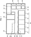
- FIG. 1 is a plan view illustrating a layout of components of a power conversion device according to a first embodiment of the invention.
- a power conversion device 100 is configured by five power units 200, each of which includes a power conversion circuit, a cooling device 300 which supplies a liquid refrigerant to the power unit 200, a control device 510 which controls power conversion of the power unit 200, an AC reactor 520 which smoothes a three-phase alternating current output from the power unit, an AC capacitor 530 which smoothes a three-phase alternating voltage output from the power unit, a contactor 540 which disconnects a current when a ground fault occurs, a motor output core 551 which eliminates three-phase AC noises of the motor output, an auxiliary power source output core 552 which eliminates the three-phase AC noises of the auxiliary power source output, a motor output terminal 560, an auxiliary power source output terminal 570, and an input terminal 580.
- These components are provided on the side surfaces or the end portions of the power conversion device 100.
- a distributing-side wire connector 351 which supplies the liquid refrigerant to the power unit 200 and a gathering-side wire connector 361 which receives the liquid refrigerant from the power unit 200 are provided respectively at five places in the cooling device 300.
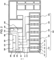
- FIG. 2 is a plan view illustrating a configuration of the cooling device which is mounted in the power conversion device according to the first embodiment of the invention and a pipe through which the liquid refrigerant is supplied to the power unit.
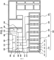
- FIG. 3 is a plan view illustrating a pipe through which the liquid refrigerant returns from the power unit to the cooling device.
- the cooling device 300 is configured by a radiator 310 which cools the liquid refrigerant, an air blower 320 which supplies a cooling air to the radiator 310, a pump 330 through which the liquid refrigerant is circulated, an expansion tank 340 which absorbs the expansion caused by a temperature rise of the liquid refrigerant, a distribution pipe 350 which supplies the liquid refrigerant to a plurality of power unit 200, a gathering pipe 360 which receives the liquid refrigerant from the plurality of power units 200, a valve 370 which performs injection and ejection of the liquid refrigerant, and the cooling device inner pipe 380 which connects these components.
- the liquid refrigerant is supplied from the pump 330 to the distribution pipe 350.
- Five distributing-side wire connectors 351 are provided in the distribution pipe 350, and the liquid refrigerant is distributed to five inlet-side pipes 411 through the distributing-side wire connector 351.
- the liquid refrigerant passed through the inlet-side pipe 411 is supplied from the inlet-side wire connector 214 to the power unit 200.
- the liquid refrigerant heated by the power unit 200 is supplied from the outlet-side wire connector 215 to an outlet-side pipe 412, and supplied to the gathering pipe 360 through the gathering-side wire connector 361.
- the liquid refrigerant is supplied from the gathering pipe 360 to the radiator 310, exchanges heat with respect to the cooling air supplied by the air blower 320 so as to be cooled down, and returns to the pump 330.
- the radiator 310 is disposed on a side near a side surface of the power conversion device 100.
- Two air blowers 320 are provided in the rear surface of the radiator 310.
- the distribution pipe 350 and the gathering pipe 360 are disposed on the center side of the power conversion device 100.
- the valve 370 is disposed next to the radiator 310 in a direction toward the side surface of the power conversion device 100.
- the pump 330 is provided next to the distribution pipe 350 and the gathering pipe 360, and the expansion tank 340 is provided on a side near an inlet of the pump.
- the first power unit 210 is configured by a plurality of semiconductor elements 211 which convert the power by switching, a cooling plate 212 which includes a flow channel of the liquid refrigerant therein, and a filter capacitor 213 which smooths a main circuit voltage.
- the semiconductor element 211 is mounted on both surfaces of the cooling plate 212, and the filter capacitor 213 is provided on the outside of the semiconductor element 211. In other words, the semiconductor element 211 and the filter capacitor 213 are provided on both surface sides with the cooling plate 212 as the center.
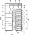
- FIG. 4 is a plan view illustrating a configuration of a main circuit wire for motor driving of the power conversion device according to the first embodiment of the invention.
- a broken line 421 in the drawing indicates a single-phase AC wire
- a dotted line 422 indicates a DC wire
- a long broken line 423 indicates a three-phase AC wire.
- the single-phase AC wire 421 is connected to main circuit terminals 226 and 246 of the second power unit 220 and the a fourth power unit 240 through the contactor 540 from the input terminal 580.
- the second power unit 220 and the fourth power unit 240 are converter circuits which convert a single-phase AC into a DC, and output the DC power to a DC wire 422.
- the main circuit terminals 226 and 246 of the second power unit 220 and the fourth power unit 240 are connected to the main circuit terminals 216 and 236 of the first power unit 210 and the third power unit 230 through the DC wire 422.
- the first power unit 210 and the third power unit 230 are inverter circuits which convert the DC into a three-phase AC, and outputs the three-phase AC power to a three-phase AC wire 423.
- the main circuit terminals 216 and 236 of the first power unit 210 and the third power unit 230 are connected to the motor output terminal 560 through the three-phase AC wire 423 and the motor output core 551.
- FIG. 5 is a plan view illustrating a configuration of the main circuit wire for auxiliary power source of the power conversion device according to the first embodiment of the invention.
- the main circuit terminals 226 and 246 of the second power unit 220 and the fourth power unit 240 of a converter circuit are connected to a main circuit terminal 256 of the fifth power unit 250 through the DC wire 422, the DC is converted into the three-phase AC for an auxiliary machine in the fifth power unit 250 of an auxiliary power source circuit.
- the three-phase AC output from the fifth power unit 250 is supplied to the reactor 520 and the AC capacitor 530 through the three-phase AC wire 423, and connected to the auxiliary power source output terminal 570 through the auxiliary power source output core 552.
- FIG. 6 is a diagram illustrating a pipe path of the power conversion device according to the first embodiment of the invention when viewed in a direction of arrow A of FIGS. 2 and 3 .
- the space 400 where the inlet-side pipe 411 and the outlet-side pipe 412 are provided is configured by an enclosed portion 414 and an opened portion 415 which are divided by the inner wall 413.
- a motor 322 of the air blower 320 is provided on a pedestal 323, and the distribution pipe 350 and the gathering pipe 360 are disposed in the opened portion 415 under the pedestal 323.
- the inlet-side pipe 411 connected to the inlet-side wire connector 214 of the first power unit 210 and the outlet-side pipe 412 connected to the outlet-side wire connector 215 are collected in the lower portion of the enclosed portion 414, and connected to the distributing-side wire connector 351 and the gathering-side wire connector 361 through a through hole provided in the inner wall 413.
- a gap between the inlet-side pipe 411 and the outlet-side pipe 412 and the through hole provided in the inner wall 413 is filled with putty, and the enclosed portion 414 is sealed with respect to the outside air.
- the other pipes connected to the power units 220, 230, 240, and 250 also have the same configuration.
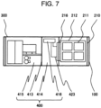
- FIG. 7 is a diagram illustrating a wire path of the power conversion device according to the first embodiment of the invention when viewed in a direction arrow B of FIGS. 4 and 5 .
- the three-phase AC wire 423 connected to the main circuit terminal 216 of the first power unit 210 is gathered in a wire installation space 416 which is provided in the upper portion in the enclosed portion 414, and connected to the motor output core 551 and the motor output terminal 560 through the wire installation space 416, so that the main circuit for motor driving illustrated in FIG. 4 is configured.
- the other wires connected to the power units 220, 230, 240, and 250 also have the same configuration.
- a cooling air 390 is inhaled from the side surface of the power conversion device 100, and passes through the radiator 310 while exchanging heat with the liquid refrigerant.
- An impeller casing 321 of the air blower 320 is provided in the space between the radiator 310, the distribution pipe 350, and the gathering pipe 360.
- the cooling air passed through the radiator 310 passes through the impeller casing 321 and discharged from the bottom surface of the power conversion device 100.
- the inlet-side wire connector 214 and the outlet-side wire connector 215 are removed from the first power unit 210, the DC wire 422 and the three-phase AC wire 423 are removed from the main circuit terminal 216, and further a control wire (not illustrated) connected to the control device 510 is removed from the first power unit 210, so that the first power unit 210 can be individually removed from the power conversion device 100.
- the inlet-side wire connector 214 and the outlet-side wire connector 215 are connected to the first power unit 210, the DC wire 422 and the three-phase AC wire 423 are connected to the main circuit terminal 216, and further the control wire is connected to the control device 510, so that the first power unit 210 can be individually installed into the power conversion device 100.
- the first power unit 210 is individually detachably attached with respect to the power conversion device 100.
- the other power units 220, 230, 240, and 250 are individually detachably attached.
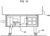
- FIG. 10 is a cross-sectional view of a railway vehicle when viewed in an advancing direction.
- the power conversion device 100 is provided below the floor of a railway vehicle 600, and the cooling device 300 inhales the air from the side surface of the railway vehicle and discharges the air to the bottom surface of the railway vehicle.
- each power unit is disposed to be detachably attached to the side surface of the railway vehicle on the side to the cooling device 300.
- the effect of the first embodiment will be described.
- a power conversion capacity of the power conversion device is large and the power conversion device is configured by a plurality of power units
- diameters of the pipes and the wires become large, and the number thereof is increased.
- the space 400 is provided in the center portion of the power conversion device 100 and the pipes 411 and 412 and the wires 421, 422, and 423 requiring a large installation space are gathered in the space 400, so that a work space for connecting the pipes and the wires can be shaped, and the power conversion device 100 can be miniaturized.
- the maintenance may start from the bottom surface of the power conversion device 100.
- the distributing-side wire connectors 351 to 355 and the gathering-side wire connectors 361 to 365 are provided in the bottom surface of the cooling device 300, and the inlet-side and outlet-side pipes 411 and 412 are connected to the wire connector through the lower portion of the space 400. Therefore, the work for detaching the pipes 411 and 412 from the cooling device 300 and detaching the cooling device 300 from the power conversion device 100 becomes easy, so that a maintenance performance can be improved. Furthermore, since the wire connectors 351 and 361 are disposed in a staggered pattern, the pipes 411 and 412 are easily detached from the bottom surface of the cooling device 300, so that the maintenance performance can be improved still more.
- the motor output terminal 560, the auxiliary power source output terminal 570, and the input terminal 580 are desirably provided in the upper portion of the power conversion device 100 in consideration of a waterproof property. Therefore, as described in the first embodiment, since the wire path can be made shortest by gathering the wires 421 and 423 in the wire installation space 416 of the upper portion of the space 400, resistance and inductance of the wire can be reduced and the wire can be reduced in weight.
- the cooling air be discharged from the bottom surface in order to extremely reduce the space where the cooling air passes in the power conversion device.
- the radiator 310 is disposed on a side near the side surface of the power conversion device 100
- the air blower 320 is disposed in the rear surface thereof
- the impeller casing 321 of the air blower 320 is provided in the space between the radiator 310, the distribution pipe 350, and the gathering pipe 360. Therefore, the space in the cooling device 300 can be effectively used, and the power conversion device 100 can be miniaturized.
- liquid refrigerant can be easily injected or discharged from the side surface of the power conversion device 100 by providing the valve 370 of the cooling device 300 in a direction facing the side surface of the power conversion device 100. Therefore, the maintenance performance can be improved.
- the maintenance performance can be improved by the configuration that a plurality of power units 200 can be individually detachably attached.
- the first embodiment has a structure which is suitable to be provided below the floor of the railway vehicle. Therefore, it is possible to provide a power conversion device which is small and easy to maintain by being provided below the floor of the railway vehicle.
- the first embodiment has been described on an assumption that five power units 200 are mounted in the power conversion device 100.
- the number of power units 200 is not limited to "5".
- the configuration of the main circuit wire is also not limited to that illustrated in FIGS. 4 and 5 .
- four semiconductor elements 211 are assumed to be provided in the side surface of the cooling plate 212 in FIGS. 6 and 7 , but the number of semiconductor elements 211 is not limited thereto.
- the distribution pipe 350 and the gathering pipe 360 may be reversely disposed in the vertical direction.
- an air filter may be provided on a windward side of the radiator as needed.
- the air blower be insulated against vibration from the radiator and the pedestal using an anti-vibration rubber.
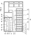
- FIG. 9 is a plan view illustrating a configuration of a cooling device which is mounted in a power conversion device according to a second example of the invention. While the valve 370 and the expansion tank 340 are provided between the radiator 310 and the pump 330 in the first embodiment, a reservior tank 341 may be provided between the gathering pipe 360 and the radiator 310 as described in the second example, and the valve 370 may be provided in the upper portion of the reservior tank. In the first embodiment, it is considered that the liquid refrigerant is injected using an exterior pump from the valve. In the configuration as described in the second example, the liquid refrigerant can be injected into the flow channel by injecting the liquid refrigerant into the reservior tank. However, when degassing in the flow channel when the liquid refrigerant is injected is took into consideration, the reservior tank 341 of the second example is necessarily provided at the highest point of the liquid refrigerant flow channel.
Landscapes
- Engineering & Computer Science (AREA)
- Microelectronics & Electronic Packaging (AREA)
- Power Engineering (AREA)
- Thermal Sciences (AREA)
- Transportation (AREA)
- Mechanical Engineering (AREA)
- Physics & Mathematics (AREA)
- Sustainable Energy (AREA)
- Sustainable Development (AREA)
- Life Sciences & Earth Sciences (AREA)
- Inverter Devices (AREA)
- Cooling Or The Like Of Electrical Apparatus (AREA)
- Cooling Or The Like Of Semiconductors Or Solid State Devices (AREA)
- Electric Propulsion And Braking For Vehicles (AREA)
Description
- The present invention relates particularly to a power conversion device which includes a system for cooling down a power conversion semiconductor element using a liquid.
- A vehicle driving control device which controls power to a vehicle driving motor and a power conversion device such as an auxiliary power source device which controls power to an onboard electric facility such as air conditioner are provided below a floor of a railway vehicle. A semiconductor element which switches a current to convert AC/DC is provided in these power conversion device.
- The semiconductor element generates heat at the time of energizing and switching. In a case where the semiconductor element is increased in temperature due to the heat, there is a concern that a conversion efficiency may be lowered and an element may be broken. Therefore, the semiconductor element is necessarily cooled down to fall within a predetermined temperature range. Since the power conversion device is mainly mounted below a floor of the vehicle where a mounting space is limited, there is a need to efficiently cool down a plurality of semiconductor elements using a small device configuration. In particular, in a case where a large amount of power conversion is required for a high-speed vehicle, a liquid cooling system is used. As a configuration of the liquid cooling system, there is known a configuration disclosed in Japanese Patent No.
4,479,305 - The power conversion device disclosed in Japanese Patent No.
4,479,305 -
EP A 2149973 proposes a power conversion apparatus and electric vehicle. -
JP2005287214 - When a power conversion capacity of a power conversion device is increased, there is a need to increase a flow rate of the liquid refrigerant which is supplied to the heat sink in order to secure a cooling performance. Further, there is a need to increase a diameter of a pipe of the liquid refrigerant in order to reduce a pressure loss. In addition, when the power conversion capacity becomes large, there is also a need to increase a wire diameter as the current is increased. Furthermore, in a case where the device is configured by a plurality of power conversion circuits, the number of pipes and wires becomes large. Therefore, there is also a need to design the power conversion device to be more miniaturized in consideration of not only a radiator and a circulation pump but also an arrangement of pipes and wires.
- In addition, the semiconductor electronic circuit component is necessarily replaced when it is out of order due to an overcurrent. Furthermore, the circulation pump is necessarily subject to the maintenance periodically. Therefore, there is a need to dispose the components in consideration of the device replacement and the easiness of the maintenance.
- The invention has been made to solve the above problems, and an object thereof is to provide a power conversion device which is small and easy to maintain.
- A power conversion device according to a first aspect of the invention for achieving the above object is provided by
claim 1. - In the power conversion device in second aspect of the invention, the cooling device is configured by a radiator that cools down the liquid refrigerant, an air blower that supplies a cooling air to the radiator, a pump that circulates the liquid refrigerant, a distribution pipe that divides and supplies the liquid refrigerant to the plurality of power units, and a gathering pipe that receives the liquid refrigerant from the plurality of power units, the plurality of cooling-device-side pipe connectors are provided in the distribution pipe and the gathering pipe, and are provided in a bottom surface of the cooling device, the air blower is provided on a windward side of the radiator, and the cooling air is supplied from a side surface of the power conversion device to the radiator, passes through a space between the distribution pipe and the gathering pipe, and is discharged from a bottom surface of the power conversion device.
- In the power conversion device in a third aspect of the invention, the plurality of cooling-device-side pipe connectors provided in the distribution pipe and the gathering pipe are disposed in a staggered pattern.
- In the power conversion device in a fourth aspect of the invention, a valve for injecting or discharging the liquid refrigerant to the cooling device is provided in at least one place of a side surface and a bottom surface of the power conversion device.
- In the power conversion device in a fifth aspect of the invention, the power conversion device is provided below a floor of a railway vehicle.
- As described above, in a case where a power conversion capacity of a power conversion device is large and the device is configured by a plurality of power conversion circuits, the pipes and the wires are increased in diameter, and the number of pipes and wires is increased. According to the first aspect of the invention, it is possible to miniaturize the power conversion device by gathering the pipes and the wires occupying a large installation space in the center space of the device.
- In addition, when the power conversion device is subjected to the maintenance, the power conversion device can be handled from the bottom surface thereof. According to the first aspect of the invention, a wire connector is provided in the bottom surface of a cooling device, and the pipe is connected to the wire connector through the lower portion of the space in a housing. Therefore, the pipe is easily detachably attached to the cooling device, and the cooling device is easily detachably attached to the housing, so that a maintenance performance can be improved.
- In addition, the cooling air is desirably discharged from the bottom surface in order to extremely reduce a space where the cooling air passes in the power conversion device. According to the second aspect of the invention, the power conversion device can be miniaturized by effectively using the space in the cooling device.
- According to the third aspect of the invention, the pipe is easily detachably attached to the bottom surface of the cooling device, so that the maintenance performance can be improved
- According to the fourth aspect of the invention, the liquid refrigerant can be easily injected or discharged from the side surface of the bottom surface of the cooling device, so that the maintenance performance can be improved.
- According to the first aspect of the invention, a power unit can be individually detachably attached, so that the maintenance performance can be improved.
- The first to fourth aspect of the invention have a structure suitable to the power conversion device which is provided below the floor of a railway vehicle. According to the fifth aspect of the invention, it is possible to provide the power conversion device which is small and easy to maintain.
- Other objects, features and advantages of the invention will become apparent from the following description of the embodiments of the invention taken in conjunction with the accompanying drawings.
-
-
FIG. 1 is a plan view illustrating a layout of components of a power conversion device according to a first embodiment of the invention; -
FIG. 2 is a plan view illustrating a configuration of a cooling device which is mounted in the power conversion device according to the first embodiment of the invention and a pipe through which a liquid refrigerant is supplied to a power unit; -
FIG. 3 is a plan view illustrating a configuration of the cooling device which is mounted in the power conversion device according to the first embodiment of the invention and a pipe through which the liquid refrigerant returns from the power unit to the cooling device; -
FIG. 4 is a plan view illustrating a configuration of a main circuit wire for motor driving of the power conversion device according to the first embodiment of the invention; -
FIG. 5 is a plan view illustrating a configuration of a main circuit wire for auxiliary power source of the power conversion device according to the first embodiment of the invention; -
FIG. 6 is a diagram illustrating a pipe path of the power conversion device according to the first embodiment of the invention when viewed in a direction of arrow A ofFIGS. 2 and3 ; -
FIG. 7 is a diagram illustrating a wire path of the power conversion device according to the first embodiment of the invention when viewed in a direction of arrow B ofFIGS. 4 and5 ; -
FIG. 8 is a diagram illustrating a position of a wire connector of the cooling device which is mounted in the power conversion device according to the first embodiment of the invention when viewed from arrow C ofFIGS. 2 and3 ; -
FIG. 9 is a plan view illustrating a configuration of a cooling device which is mounted in a power conversion device according to a second example of the invention; and -
FIG. 10 is a cross-sectional view of a railway vehicle when viewed in an advancing direction. - Hereinafter, embodiments of the invention will be described with reference to the drawings.
-
FIG. 1 is a plan view illustrating a layout of components of a power conversion device according to a first embodiment of the invention. Apower conversion device 100 is configured by fivepower units 200, each of which includes a power conversion circuit, acooling device 300 which supplies a liquid refrigerant to thepower unit 200, acontrol device 510 which controls power conversion of thepower unit 200, anAC reactor 520 which smoothes a three-phase alternating current output from the power unit, anAC capacitor 530 which smoothes a three-phase alternating voltage output from the power unit, acontactor 540 which disconnects a current when a ground fault occurs, amotor output core 551 which eliminates three-phase AC noises of the motor output, an auxiliary powersource output core 552 which eliminates the three-phase AC noises of the auxiliary power source output, amotor output terminal 560, an auxiliary powersource output terminal 570, and aninput terminal 580. These components are provided on the side surfaces or the end portions of thepower conversion device 100. Aspace 400 is provided in a portion surrounded by a dotted line in the center portion of thepower conversion device 100 illustrated inFIG. 1 . - A wire connector and a main circuit terminal of the
power unit 200 will be described using afirst power unit 210 as an example. In thefirst power unit 210, an inlet-side wire connector 214 through which the liquid refrigerant is supplied from thecooling device 300, an outlet-side wire connector 215 through which the liquid refrigerant returns to thecooling device 300, and amain circuit terminal 216 are provided at positions abutting on thespace 400. Theother power units - In addition, a distributing-
side wire connector 351 which supplies the liquid refrigerant to thepower unit 200 and a gathering-side wire connector 361 which receives the liquid refrigerant from thepower unit 200 are provided respectively at five places in thecooling device 300. - The description will be made about a configuration of a pipe through which the cooling device and the liquid refrigerant flow.
FIG. 2 is a plan view illustrating a configuration of the cooling device which is mounted in the power conversion device according to the first embodiment of the invention and a pipe through which the liquid refrigerant is supplied to the power unit. In addition,FIG. 3 is a plan view illustrating a pipe through which the liquid refrigerant returns from the power unit to the cooling device. Thecooling device 300 is configured by aradiator 310 which cools the liquid refrigerant, anair blower 320 which supplies a cooling air to theradiator 310, apump 330 through which the liquid refrigerant is circulated, anexpansion tank 340 which absorbs the expansion caused by a temperature rise of the liquid refrigerant, adistribution pipe 350 which supplies the liquid refrigerant to a plurality ofpower unit 200, agathering pipe 360 which receives the liquid refrigerant from the plurality ofpower units 200, avalve 370 which performs injection and ejection of the liquid refrigerant, and the cooling deviceinner pipe 380 which connects these components. The liquid refrigerant is supplied from thepump 330 to thedistribution pipe 350. Five distributing-side wire connectors 351 are provided in thedistribution pipe 350, and the liquid refrigerant is distributed to five inlet-side pipes 411 through the distributing-side wire connector 351. The liquid refrigerant passed through the inlet-side pipe 411 is supplied from the inlet-side wire connector 214 to thepower unit 200. The liquid refrigerant heated by thepower unit 200 is supplied from the outlet-side wire connector 215 to an outlet-side pipe 412, and supplied to thegathering pipe 360 through the gathering-side wire connector 361. The liquid refrigerant is supplied from thegathering pipe 360 to theradiator 310, exchanges heat with respect to the cooling air supplied by theair blower 320 so as to be cooled down, and returns to thepump 330. - Next, the layout of the components in the
cooling device 300 will be described. Theradiator 310 is disposed on a side near a side surface of thepower conversion device 100. Twoair blowers 320 are provided in the rear surface of theradiator 310. Thedistribution pipe 350 and thegathering pipe 360 are disposed on the center side of thepower conversion device 100. Thevalve 370 is disposed next to theradiator 310 in a direction toward the side surface of thepower conversion device 100. Thepump 330 is provided next to thedistribution pipe 350 and thegathering pipe 360, and theexpansion tank 340 is provided on a side near an inlet of the pump. - Next, the configuration of the
power unit 200 will be described using thefirst power unit 210 as an example. Thefirst power unit 210 is configured by a plurality ofsemiconductor elements 211 which convert the power by switching, acooling plate 212 which includes a flow channel of the liquid refrigerant therein, and afilter capacitor 213 which smooths a main circuit voltage. Thesemiconductor element 211 is mounted on both surfaces of thecooling plate 212, and thefilter capacitor 213 is provided on the outside of thesemiconductor element 211. In other words, thesemiconductor element 211 and thefilter capacitor 213 are provided on both surface sides with thecooling plate 212 as the center. The inlet-side wire connector 214 and the outlet-side wire connector 215 are connected to thecooling plate 212, and communicate with the flow channel provided in thecooling plate 212, so that the flow channel of the liquid refrigerant is configured. In addition, thesemiconductor element 211, thefilter capacitor 213, and themain circuit terminal 216 are electrically connected to configure a main circuit of thefirst power unit 210. Theother power units - First, the description will be made about a configuration of a main circuit wire for motor driving.
FIG. 4 is a plan view illustrating a configuration of a main circuit wire for motor driving of the power conversion device according to the first embodiment of the invention. Abroken line 421 in the drawing indicates a single-phase AC wire, adotted line 422 indicates a DC wire, and a long brokenline 423 indicates a three-phase AC wire. The single-phase AC wire 421 is connected tomain circuit terminals second power unit 220 and the afourth power unit 240 through the contactor 540 from theinput terminal 580. Thesecond power unit 220 and thefourth power unit 240 are converter circuits which convert a single-phase AC into a DC, and output the DC power to aDC wire 422. Themain circuit terminals second power unit 220 and thefourth power unit 240 are connected to themain circuit terminals first power unit 210 and thethird power unit 230 through theDC wire 422. Thefirst power unit 210 and thethird power unit 230 are inverter circuits which convert the DC into a three-phase AC, and outputs the three-phase AC power to a three-phase AC wire 423. Themain circuit terminals first power unit 210 and thethird power unit 230 are connected to themotor output terminal 560 through the three-phase AC wire 423 and themotor output core 551. - Next, the description will be made about a configuration of a main circuit wire for auxiliary power source.
FIG. 5 is a plan view illustrating a configuration of the main circuit wire for auxiliary power source of the power conversion device according to the first embodiment of the invention. In the main circuit for auxiliary power source, themain circuit terminals second power unit 220 and thefourth power unit 240 of a converter circuit are connected to amain circuit terminal 256 of thefifth power unit 250 through theDC wire 422, the DC is converted into the three-phase AC for an auxiliary machine in thefifth power unit 250 of an auxiliary power source circuit. The three-phase AC output from thefifth power unit 250 is supplied to thereactor 520 and theAC capacitor 530 through the three-phase AC wire 423, and connected to the auxiliary powersource output terminal 570 through the auxiliary powersource output core 552. - Next, a pipe path and a position of the wire connector will be described using the
first power unit 210 as an example.FIG. 6 is a diagram illustrating a pipe path of the power conversion device according to the first embodiment of the invention when viewed in a direction of arrow A ofFIGS. 2 and3 . Thespace 400 where the inlet-side pipe 411 and the outlet-side pipe 412 are provided is configured by anenclosed portion 414 and an openedportion 415 which are divided by theinner wall 413. Amotor 322 of theair blower 320 is provided on apedestal 323, and thedistribution pipe 350 and thegathering pipe 360 are disposed in the openedportion 415 under thepedestal 323. The inlet-side pipe 411 connected to the inlet-side wire connector 214 of thefirst power unit 210 and the outlet-side pipe 412 connected to the outlet-side wire connector 215 are collected in the lower portion of theenclosed portion 414, and connected to the distributing-side wire connector 351 and the gathering-side wire connector 361 through a through hole provided in theinner wall 413. A gap between the inlet-side pipe 411 and the outlet-side pipe 412 and the through hole provided in theinner wall 413 is filled with putty, and theenclosed portion 414 is sealed with respect to the outside air. The other pipes connected to thepower units - Next, the description will be made about a wire path using the
first power unit 210 as an example.FIG. 7 is a diagram illustrating a wire path of the power conversion device according to the first embodiment of the invention when viewed in a direction arrow B ofFIGS. 4 and5 . The three-phase AC wire 423 connected to themain circuit terminal 216 of thefirst power unit 210 is gathered in awire installation space 416 which is provided in the upper portion in theenclosed portion 414, and connected to themotor output core 551 and themotor output terminal 560 through thewire installation space 416, so that the main circuit for motor driving illustrated inFIG. 4 is configured. The other wires connected to thepower units - Next, a flow of the cooling air in the
cooling device 300 will be described. As illustrated inFIG. 6 , a coolingair 390 is inhaled from the side surface of thepower conversion device 100, and passes through theradiator 310 while exchanging heat with the liquid refrigerant. Animpeller casing 321 of theair blower 320 is provided in the space between theradiator 310, thedistribution pipe 350, and thegathering pipe 360. The cooling air passed through theradiator 310 passes through theimpeller casing 321 and discharged from the bottom surface of thepower conversion device 100. - A position of the wire connector of the
cooling device 300 will be described.FIG. 8 is a diagram illustrating a position of the wire connector of the cooling device which is mounted in the power conversion device according to the first embodiment of the invention when viewed in a direction of arrow C ofFIGS. 2 and3 . In the first embodiment, thedistribution pipe 350 is disposed below thegathering pipe 360. Fivewire connectors 351 provided on thedistribution pipe 350 and fivewire connector 361 provided on thegathering pipe 360 are disposed in a staggered pattern. - Next, the description will be made about detaching of the power unit using the
first power unit 210 as an example. When thefirst power unit 210 is removed from thepower conversion device 100, the inlet-side wire connector 214 and the outlet-side wire connector 215 are removed from thefirst power unit 210, theDC wire 422 and the three-phase AC wire 423 are removed from themain circuit terminal 216, and further a control wire (not illustrated) connected to thecontrol device 510 is removed from thefirst power unit 210, so that thefirst power unit 210 can be individually removed from thepower conversion device 100. In addition, when installing, the inlet-side wire connector 214 and the outlet-side wire connector 215 are connected to thefirst power unit 210, theDC wire 422 and the three-phase AC wire 423 are connected to themain circuit terminal 216, and further the control wire is connected to thecontrol device 510, so that thefirst power unit 210 can be individually installed into thepower conversion device 100. In this way, thefirst power unit 210 is individually detachably attached with respect to thepower conversion device 100. Theother power units -
FIG. 10 is a cross-sectional view of a railway vehicle when viewed in an advancing direction. Thepower conversion device 100 is provided below the floor of arailway vehicle 600, and thecooling device 300 inhales the air from the side surface of the railway vehicle and discharges the air to the bottom surface of the railway vehicle. In addition, each power unit is disposed to be detachably attached to the side surface of the railway vehicle on the side to thecooling device 300. - Herein, the effect of the first embodiment will be described. In a case where a power conversion capacity of the power conversion device is large and the power conversion device is configured by a plurality of power units, diameters of the pipes and the wires become large, and the number thereof is increased. As described in the first embodiment, the
space 400 is provided in the center portion of thepower conversion device 100 and thepipes wires space 400, so that a work space for connecting the pipes and the wires can be shaped, and thepower conversion device 100 can be miniaturized. - In addition, when the
cooling device 300 is maintained, the maintenance may start from the bottom surface of thepower conversion device 100. The distributing-side wire connectors 351 to 355 and the gathering-side wire connectors 361 to 365 are provided in the bottom surface of thecooling device 300, and the inlet-side and outlet-side pipes space 400. Therefore, the work for detaching thepipes cooling device 300 and detaching thecooling device 300 from thepower conversion device 100 becomes easy, so that a maintenance performance can be improved. Furthermore, since thewire connectors pipes cooling device 300, so that the maintenance performance can be improved still more. - In addition, in the
power conversion device 100, themotor output terminal 560, the auxiliary powersource output terminal 570, and theinput terminal 580 are desirably provided in the upper portion of thepower conversion device 100 in consideration of a waterproof property. Therefore, as described in the first embodiment, since the wire path can be made shortest by gathering thewires wire installation space 416 of the upper portion of thespace 400, resistance and inductance of the wire can be reduced and the wire can be reduced in weight. - In addition, it is desirable that the cooling air be discharged from the bottom surface in order to extremely reduce the space where the cooling air passes in the power conversion device. As described in the first embodiment, the
radiator 310 is disposed on a side near the side surface of thepower conversion device 100, theair blower 320 is disposed in the rear surface thereof, and theimpeller casing 321 of theair blower 320 is provided in the space between theradiator 310, thedistribution pipe 350, and thegathering pipe 360. Therefore, the space in thecooling device 300 can be effectively used, and thepower conversion device 100 can be miniaturized. - In addition, the liquid refrigerant can be easily injected or discharged from the side surface of the
power conversion device 100 by providing thevalve 370 of thecooling device 300 in a direction facing the side surface of thepower conversion device 100. Therefore, the maintenance performance can be improved. - In addition, the maintenance performance can be improved by the configuration that a plurality of
power units 200 can be individually detachably attached. - In addition, the first embodiment has a structure which is suitable to be provided below the floor of the railway vehicle. Therefore, it is possible to provide a power conversion device which is small and easy to maintain by being provided below the floor of the railway vehicle.
- Further, the first embodiment has been described on an assumption that five
power units 200 are mounted in thepower conversion device 100. However, the number ofpower units 200 is not limited to "5". In addition, the configuration of the main circuit wire is also not limited to that illustrated inFIGS. 4 and5 . In addition, foursemiconductor elements 211 are assumed to be provided in the side surface of thecooling plate 212 inFIGS. 6 and7 , but the number ofsemiconductor elements 211 is not limited thereto. In addition, thedistribution pipe 350 and thegathering pipe 360 may be reversely disposed in the vertical direction. - Furthermore, an air filter may be provided on a windward side of the radiator as needed. In addition, it is desirable that the air blower be insulated against vibration from the radiator and the pedestal using an anti-vibration rubber.
-
FIG. 9 is a plan view illustrating a configuration of a cooling device which is mounted in a power conversion device according to a second example of the invention. While thevalve 370 and theexpansion tank 340 are provided between theradiator 310 and thepump 330 in the first embodiment, areservior tank 341 may be provided between the gatheringpipe 360 and theradiator 310 as described in the second example, and thevalve 370 may be provided in the upper portion of the reservior tank. In the first embodiment, it is considered that the liquid refrigerant is injected using an exterior pump from the valve. In the configuration as described in the second example, the liquid refrigerant can be injected into the flow channel by injecting the liquid refrigerant into the reservior tank. However, when degassing in the flow channel when the liquid refrigerant is injected is took into consideration, thereservior tank 341 of the second example is necessarily provided at the highest point of the liquid refrigerant flow channel.
Claims (5)
- A power conversion device (100) comprising:a plurality of power units (200), each of which is provided with a power conversion circuit;a plurality of wires through which power is input and output with respect to the plurality of power units (200); anda cooling device (300) that supplies a liquid refrigerant to the plurality of power units (200); anda plurality of pipes that connect the plurality of power units (200) and the cooling device (300),wherein a space (400) is provided in the center portion of the power conversion device (100) to gather the plurality of wires and the plurality of pipes,main circuit terminals (216, 226, 236, 246) that connect the plurality of wires to the plurality of power units (200), a plurality of power-unit-side pipe connectors (214, 215) that connect the plurality of pipes to the plurality of power units (200), and a plurality of cooling-device-side pipe connectors (351, 361) that connect the plurality of pipes to the cooling device (300) are disposed at positions abutting on the space (400),the plurality of cooling-device-side pipe connectors are provided in a bottom surface of the cooling device (300),the plurality of pipes are connected to the plurality of cooling-device-side pipe connectors through a lower portion of the space (400) from the plurality of power-unit-side pipe connectors,the plurality of wires are connected to an input and an output of the power conversion device (100) through an upper portion of the space (400) from main circuit terminals of the plurality of power units (200), andthe plurality of power units (200) are each configured to be detachably attached to the power conversion device (100).
- The power conversion device (100) according to claim 1,wherein the cooling device (300) is configured by a radiator (310) that cools down the liquid refrigerant, an air blower (320) that supplies a cooling air to the radiator (310), a pump (330) that circulates the liquid refrigerant, a distribution pipe (350) that divides and supplies the liquid refrigerant to the plurality of power units (200), and a gathering pipe (360) that receives the liquid refrigerant from the plurality of power units (200),the plurality of cooling-device-side pipe connectors are provided in the distribution pipe (350) and the gathering pipe (360), and are provided in a bottom surface of the cooling device (300),the air blower (320) is provided on a windward side of the radiator (310), andthe cooling air is supplied from a side surface of the power conversion device (100) to the radiator (310), passes through a space between the distribution pipe (350) and the gathering pipe (360), and is discharged from a bottom surface of the power conversion device (100).
- The power conversion device (100) according to claim 2,
wherein the plurality of cooling-device-side pipe connectors provided in the distribution pipe (350) and the gathering pipe (360) are disposed in a staggered pattern. - The power conversion device (100) according to any one of claims 1 to 3,
wherein a valve (370) for injecting or discharging the liquid refrigerant to the cooling device (300) is provided in at least one place of a side surface and a bottom surface of the power conversion device (100). - The power conversion device (100) according to any one of claims 1 to 4,
wherein the power conversion device (100) is provided below a floor of a railway vehicle (600).
Applications Claiming Priority (1)
| Application Number | Priority Date | Filing Date | Title |
|---|---|---|---|
| JP2016067033A JP6470220B2 (en) | 2016-03-30 | 2016-03-30 | Power converter |
Publications (3)
| Publication Number | Publication Date |
|---|---|
| EP3228490A1 EP3228490A1 (en) | 2017-10-11 |
| EP3228490B1 EP3228490B1 (en) | 2019-12-18 |
| EP3228490B2 true EP3228490B2 (en) | 2025-01-15 |
Family
ID=57890670
Family Applications (1)
| Application Number | Title | Priority Date | Filing Date |
|---|---|---|---|
| EP17152507.4A Active EP3228490B2 (en) | 2016-03-30 | 2017-01-20 | Power conversion device |
Country Status (3)
| Country | Link |
|---|---|
| EP (1) | EP3228490B2 (en) |
| JP (1) | JP6470220B2 (en) |
| CN (1) | CN107294356B (en) |
Families Citing this family (4)
| Publication number | Priority date | Publication date | Assignee | Title |
|---|---|---|---|---|
| DE102018129835A1 (en) | 2018-11-26 | 2020-05-28 | Beckhoff Automation Gmbh | Control system, coupler module and method for assembling a control system |
| EP3925847A4 (en) | 2019-02-13 | 2022-10-26 | Hitachi, Ltd. | RAILWAY VEHICLE CONTROL DEVICE, RAILWAY VEHICLE AND METHOD FOR MANUFACTURING THE RAILWAY VEHICLE |
| CN113677169A (en) * | 2021-09-10 | 2021-11-19 | 新风光电子科技股份有限公司 | Separated phase-change heat dissipation inverter |
| CN115051532A (en) * | 2022-05-10 | 2022-09-13 | 京清数电(北京)技术有限公司 | Energy storage converter |
Citations (5)
| Publication number | Priority date | Publication date | Assignee | Title |
|---|---|---|---|---|
| JPS62299474A (en) † | 1986-06-20 | 1987-12-26 | 株式会社日立製作所 | Railway vehicle underfloor fitting structure |
| JPH09219904A (en) † | 1996-02-14 | 1997-08-19 | Hitachi Ltd | Electric vehicle power converter |
| DE19524115C2 (en) † | 1995-07-03 | 2000-03-23 | Abb Patent Gmbh | Power converter device with subdivided functional rooms |
| EP1881590A2 (en) † | 2006-07-21 | 2008-01-23 | Hitachi, Ltd. | Power converter |
| EP2441639A1 (en) † | 2009-06-12 | 2012-04-18 | Mitsubishi Electric Corporation | Electric power conversion device for vehicle |
Family Cites Families (10)
| Publication number | Priority date | Publication date | Assignee | Title |
|---|---|---|---|---|
| JP2004328838A (en) * | 2003-04-22 | 2004-11-18 | Fuji Electric Systems Co Ltd | Cooling device and auxiliary power supply for electric railway vehicle |
| JP4479305B2 (en) * | 2004-03-30 | 2010-06-09 | 三菱電機株式会社 | Power converter |
| JPWO2007138645A1 (en) * | 2006-05-25 | 2009-10-01 | 三菱電機株式会社 | Auxiliary power supply for vehicle |
| JP4657329B2 (en) * | 2008-07-29 | 2011-03-23 | 日立オートモティブシステムズ株式会社 | Power converter and electric vehicle |
| CN201590748U (en) * | 2009-11-27 | 2010-09-22 | 艾默生网络能源有限公司 | A converter and its main power structure |
| CN102163907B (en) * | 2011-01-28 | 2014-03-12 | 中国电力科学研究院 | Voltage source inverter basic function unit based on total control device |
| DE102011082516B4 (en) * | 2011-09-12 | 2019-09-05 | Siemens Mobility GmbH | Train of railway vehicles |
| CN102437714A (en) * | 2011-12-29 | 2012-05-02 | 徐州中矿大传动与自动化有限公司 | Three-level frequency converter water-cooling heat dissipation structure |
| JP2013216216A (en) * | 2012-04-10 | 2013-10-24 | Ntn Corp | Cooling structure of inverter device |
| JP2014117121A (en) * | 2012-12-12 | 2014-06-26 | Toshiba Corp | Cooling device, cooling method, and railway vehicle |
-
2016
- 2016-03-30 JP JP2016067033A patent/JP6470220B2/en active Active
- 2016-09-22 CN CN201610842691.9A patent/CN107294356B/en active Active
-
2017
- 2017-01-20 EP EP17152507.4A patent/EP3228490B2/en active Active
Patent Citations (5)
| Publication number | Priority date | Publication date | Assignee | Title |
|---|---|---|---|---|
| JPS62299474A (en) † | 1986-06-20 | 1987-12-26 | 株式会社日立製作所 | Railway vehicle underfloor fitting structure |
| DE19524115C2 (en) † | 1995-07-03 | 2000-03-23 | Abb Patent Gmbh | Power converter device with subdivided functional rooms |
| JPH09219904A (en) † | 1996-02-14 | 1997-08-19 | Hitachi Ltd | Electric vehicle power converter |
| EP1881590A2 (en) † | 2006-07-21 | 2008-01-23 | Hitachi, Ltd. | Power converter |
| EP2441639A1 (en) † | 2009-06-12 | 2012-04-18 | Mitsubishi Electric Corporation | Electric power conversion device for vehicle |
Non-Patent Citations (1)
| Title |
|---|
| ANONYMOUS: "Wasserkühlung", WIKIPEDIA, 21 October 2015 (2015-10-21), Retrieved from the Internet <URL:https://de.wikipedia.org/w/index.php?title=Wasserkühlung&oldid=147228925> † |
Also Published As
| Publication number | Publication date |
|---|---|
| JP2017184412A (en) | 2017-10-05 |
| CN107294356B (en) | 2019-12-31 |
| CN107294356A (en) | 2017-10-24 |
| JP6470220B2 (en) | 2019-02-13 |
| EP3228490A1 (en) | 2017-10-11 |
| EP3228490B1 (en) | 2019-12-18 |
Similar Documents
| Publication | Publication Date | Title |
|---|---|---|
| JP5694278B2 (en) | Power converter | |
| EP3228490B2 (en) | Power conversion device | |
| CN107078652B (en) | Inverter with multi-part housing and internal cooling air channels | |
| CN109588000B (en) | Integrated traction converter cooling system | |
| US8837119B2 (en) | Matrix converter | |
| CN101834560B (en) | Arrangement for a motor controller | |
| US9153374B2 (en) | Cooling arrangements for drive systems | |
| JP5265825B1 (en) | Power control unit | |
| JP6812317B2 (en) | Vehicles equipped with power converters and power converters | |
| WO2014141486A1 (en) | Uninterruptible power source apparatus | |
| EP1863156A1 (en) | Power converter cooling structure | |
| EP3819158B1 (en) | Integrated controller of vehicle and vehicle | |
| EP3945762B1 (en) | Scalable modular cooling unit having voltage isolation | |
| US7061759B2 (en) | Arrangement for the placement of frequency converters | |
| CN114301262A (en) | High voltage platform and motor controller thereof | |
| CN118017800A (en) | Inverter with capacitor discharge and DC bus filtering | |
| KR101155300B1 (en) | Distributing board comprising apparatus for cooling bus bar | |
| CN110168909B (en) | Power conversion device | |
| CN121530189A (en) | Energy storage converters and their energy storage systems | |
| CN105703604A (en) | Diesel locomotive traction transformer and diesel locomotive | |
| KR20170062065A (en) | Submodule for HVDC system | |
| CN221728099U (en) | A permanent magnet motor and controller integrated structure | |
| CN222814125U (en) | Hydrogen power supply | |
| CN111262452A (en) | High frequency medium voltage drive system for high speed machine applications | |
| CN206442306U (en) | Power model on electric tracks vehicle |
Legal Events
| Date | Code | Title | Description |
|---|---|---|---|
| PUAI | Public reference made under article 153(3) epc to a published international application that has entered the european phase |
Free format text: ORIGINAL CODE: 0009012 |
|
| STAA | Information on the status of an ep patent application or granted ep patent |
Free format text: STATUS: REQUEST FOR EXAMINATION WAS MADE |
|
| 17P | Request for examination filed |
Effective date: 20170127 |
|
| AK | Designated contracting states |
Kind code of ref document: A1 Designated state(s): AL AT BE BG CH CY CZ DE DK EE ES FI FR GB GR HR HU IE IS IT LI LT LU LV MC MK MT NL NO PL PT RO RS SE SI SK SM TR |
|
| AX | Request for extension of the european patent |
Extension state: BA ME |
|
| RIC1 | Information provided on ipc code assigned before grant |
Ipc: B60L 1/00 20060101AFI20190613BHEP Ipc: B60L 3/00 20190101ALI20190613BHEP Ipc: H02M 7/00 20060101ALI20190613BHEP Ipc: H05K 7/20 20060101ALI20190613BHEP Ipc: H01L 23/34 20060101ALI20190613BHEP |
|
| GRAP | Despatch of communication of intention to grant a patent |
Free format text: ORIGINAL CODE: EPIDOSNIGR1 |
|
| STAA | Information on the status of an ep patent application or granted ep patent |
Free format text: STATUS: GRANT OF PATENT IS INTENDED |
|
| INTG | Intention to grant announced |
Effective date: 20190731 |
|
| GRAS | Grant fee paid |
Free format text: ORIGINAL CODE: EPIDOSNIGR3 |
|
| GRAA | (expected) grant |
Free format text: ORIGINAL CODE: 0009210 |
|
| STAA | Information on the status of an ep patent application or granted ep patent |
Free format text: STATUS: THE PATENT HAS BEEN GRANTED |
|
| AK | Designated contracting states |
Kind code of ref document: B1 Designated state(s): AL AT BE BG CH CY CZ DE DK EE ES FI FR GB GR HR HU IE IS IT LI LT LU LV MC MK MT NL NO PL PT RO RS SE SI SK SM TR |
|
| REG | Reference to a national code |
Ref country code: CH Ref legal event code: EP |
|
| REG | Reference to a national code |
Ref country code: IE Ref legal event code: FG4D |
|
| REG | Reference to a national code |
Ref country code: DE Ref legal event code: R096 Ref document number: 602017009707 Country of ref document: DE |
|
| REG | Reference to a national code |
Ref country code: AT Ref legal event code: REF Ref document number: 1214208 Country of ref document: AT Kind code of ref document: T Effective date: 20200115 |
|
| REG | Reference to a national code |
Ref country code: NL Ref legal event code: MP Effective date: 20191218 |
|
| PG25 | Lapsed in a contracting state [announced via postgrant information from national office to epo] |
Ref country code: LV Free format text: LAPSE BECAUSE OF FAILURE TO SUBMIT A TRANSLATION OF THE DESCRIPTION OR TO PAY THE FEE WITHIN THE PRESCRIBED TIME-LIMIT Effective date: 20191218 Ref country code: SE Free format text: LAPSE BECAUSE OF FAILURE TO SUBMIT A TRANSLATION OF THE DESCRIPTION OR TO PAY THE FEE WITHIN THE PRESCRIBED TIME-LIMIT Effective date: 20191218 Ref country code: BG Free format text: LAPSE BECAUSE OF FAILURE TO SUBMIT A TRANSLATION OF THE DESCRIPTION OR TO PAY THE FEE WITHIN THE PRESCRIBED TIME-LIMIT Effective date: 20200318 Ref country code: FI Free format text: LAPSE BECAUSE OF FAILURE TO SUBMIT A TRANSLATION OF THE DESCRIPTION OR TO PAY THE FEE WITHIN THE PRESCRIBED TIME-LIMIT Effective date: 20191218 Ref country code: GR Free format text: LAPSE BECAUSE OF FAILURE TO SUBMIT A TRANSLATION OF THE DESCRIPTION OR TO PAY THE FEE WITHIN THE PRESCRIBED TIME-LIMIT Effective date: 20200319 Ref country code: NO Free format text: LAPSE BECAUSE OF FAILURE TO SUBMIT A TRANSLATION OF THE DESCRIPTION OR TO PAY THE FEE WITHIN THE PRESCRIBED TIME-LIMIT Effective date: 20200318 Ref country code: LT Free format text: LAPSE BECAUSE OF FAILURE TO SUBMIT A TRANSLATION OF THE DESCRIPTION OR TO PAY THE FEE WITHIN THE PRESCRIBED TIME-LIMIT Effective date: 20191218 |
|
| REG | Reference to a national code |
Ref country code: LT Ref legal event code: MG4D |
|
| PG25 | Lapsed in a contracting state [announced via postgrant information from national office to epo] |
Ref country code: HR Free format text: LAPSE BECAUSE OF FAILURE TO SUBMIT A TRANSLATION OF THE DESCRIPTION OR TO PAY THE FEE WITHIN THE PRESCRIBED TIME-LIMIT Effective date: 20191218 Ref country code: RS Free format text: LAPSE BECAUSE OF FAILURE TO SUBMIT A TRANSLATION OF THE DESCRIPTION OR TO PAY THE FEE WITHIN THE PRESCRIBED TIME-LIMIT Effective date: 20191218 |
|
| PG25 | Lapsed in a contracting state [announced via postgrant information from national office to epo] |
Ref country code: AL Free format text: LAPSE BECAUSE OF FAILURE TO SUBMIT A TRANSLATION OF THE DESCRIPTION OR TO PAY THE FEE WITHIN THE PRESCRIBED TIME-LIMIT Effective date: 20191218 |
|
| PG25 | Lapsed in a contracting state [announced via postgrant information from national office to epo] |
Ref country code: EE Free format text: LAPSE BECAUSE OF FAILURE TO SUBMIT A TRANSLATION OF THE DESCRIPTION OR TO PAY THE FEE WITHIN THE PRESCRIBED TIME-LIMIT Effective date: 20191218 Ref country code: NL Free format text: LAPSE BECAUSE OF FAILURE TO SUBMIT A TRANSLATION OF THE DESCRIPTION OR TO PAY THE FEE WITHIN THE PRESCRIBED TIME-LIMIT Effective date: 20191218 Ref country code: CZ Free format text: LAPSE BECAUSE OF FAILURE TO SUBMIT A TRANSLATION OF THE DESCRIPTION OR TO PAY THE FEE WITHIN THE PRESCRIBED TIME-LIMIT Effective date: 20191218 Ref country code: PT Free format text: LAPSE BECAUSE OF FAILURE TO SUBMIT A TRANSLATION OF THE DESCRIPTION OR TO PAY THE FEE WITHIN THE PRESCRIBED TIME-LIMIT Effective date: 20200513 Ref country code: RO Free format text: LAPSE BECAUSE OF FAILURE TO SUBMIT A TRANSLATION OF THE DESCRIPTION OR TO PAY THE FEE WITHIN THE PRESCRIBED TIME-LIMIT Effective date: 20191218 |
|
| PG25 | Lapsed in a contracting state [announced via postgrant information from national office to epo] |
Ref country code: SM Free format text: LAPSE BECAUSE OF FAILURE TO SUBMIT A TRANSLATION OF THE DESCRIPTION OR TO PAY THE FEE WITHIN THE PRESCRIBED TIME-LIMIT Effective date: 20191218 Ref country code: SK Free format text: LAPSE BECAUSE OF FAILURE TO SUBMIT A TRANSLATION OF THE DESCRIPTION OR TO PAY THE FEE WITHIN THE PRESCRIBED TIME-LIMIT Effective date: 20191218 Ref country code: IS Free format text: LAPSE BECAUSE OF FAILURE TO SUBMIT A TRANSLATION OF THE DESCRIPTION OR TO PAY THE FEE WITHIN THE PRESCRIBED TIME-LIMIT Effective date: 20200418 |
|
| REG | Reference to a national code |
Ref country code: CH Ref legal event code: PL |
|
| REG | Reference to a national code |
Ref country code: DE Ref legal event code: R026 Ref document number: 602017009707 Country of ref document: DE |
|
| PLBI | Opposition filed |
Free format text: ORIGINAL CODE: 0009260 |
|
| PG25 | Lapsed in a contracting state [announced via postgrant information from national office to epo] |
Ref country code: MC Free format text: LAPSE BECAUSE OF FAILURE TO SUBMIT A TRANSLATION OF THE DESCRIPTION OR TO PAY THE FEE WITHIN THE PRESCRIBED TIME-LIMIT Effective date: 20191218 |
|
| PLAX | Notice of opposition and request to file observation + time limit sent |
Free format text: ORIGINAL CODE: EPIDOSNOBS2 |
|
| REG | Reference to a national code |
Ref country code: AT Ref legal event code: MK05 Ref document number: 1214208 Country of ref document: AT Kind code of ref document: T Effective date: 20191218 Ref country code: BE Ref legal event code: MM Effective date: 20200131 |
|
| 26 | Opposition filed |
Opponent name: BOMBARDIER TRANSPORTATION GMBH Effective date: 20200915 |
|
| PG25 | Lapsed in a contracting state [announced via postgrant information from national office to epo] |
Ref country code: LU Free format text: LAPSE BECAUSE OF NON-PAYMENT OF DUE FEES Effective date: 20200120 Ref country code: DK Free format text: LAPSE BECAUSE OF FAILURE TO SUBMIT A TRANSLATION OF THE DESCRIPTION OR TO PAY THE FEE WITHIN THE PRESCRIBED TIME-LIMIT Effective date: 20191218 Ref country code: ES Free format text: LAPSE BECAUSE OF FAILURE TO SUBMIT A TRANSLATION OF THE DESCRIPTION OR TO PAY THE FEE WITHIN THE PRESCRIBED TIME-LIMIT Effective date: 20191218 |
|
| PG25 | Lapsed in a contracting state [announced via postgrant information from national office to epo] |
Ref country code: SI Free format text: LAPSE BECAUSE OF FAILURE TO SUBMIT A TRANSLATION OF THE DESCRIPTION OR TO PAY THE FEE WITHIN THE PRESCRIBED TIME-LIMIT Effective date: 20191218 Ref country code: BE Free format text: LAPSE BECAUSE OF NON-PAYMENT OF DUE FEES Effective date: 20200131 Ref country code: AT Free format text: LAPSE BECAUSE OF FAILURE TO SUBMIT A TRANSLATION OF THE DESCRIPTION OR TO PAY THE FEE WITHIN THE PRESCRIBED TIME-LIMIT Effective date: 20191218 Ref country code: CH Free format text: LAPSE BECAUSE OF NON-PAYMENT OF DUE FEES Effective date: 20200131 Ref country code: LI Free format text: LAPSE BECAUSE OF NON-PAYMENT OF DUE FEES Effective date: 20200131 |
|
| PG25 | Lapsed in a contracting state [announced via postgrant information from national office to epo] |
Ref country code: FR Free format text: LAPSE BECAUSE OF NON-PAYMENT OF DUE FEES Effective date: 20200218 Ref country code: IE Free format text: LAPSE BECAUSE OF NON-PAYMENT OF DUE FEES Effective date: 20200120 |
|
| PLBB | Reply of patent proprietor to notice(s) of opposition received |
Free format text: ORIGINAL CODE: EPIDOSNOBS3 |
|
| PG25 | Lapsed in a contracting state [announced via postgrant information from national office to epo] |
Ref country code: PL Free format text: LAPSE BECAUSE OF FAILURE TO SUBMIT A TRANSLATION OF THE DESCRIPTION OR TO PAY THE FEE WITHIN THE PRESCRIBED TIME-LIMIT Effective date: 20191218 |
|
| PG25 | Lapsed in a contracting state [announced via postgrant information from national office to epo] |
Ref country code: TR Free format text: LAPSE BECAUSE OF FAILURE TO SUBMIT A TRANSLATION OF THE DESCRIPTION OR TO PAY THE FEE WITHIN THE PRESCRIBED TIME-LIMIT Effective date: 20191218 Ref country code: MT Free format text: LAPSE BECAUSE OF FAILURE TO SUBMIT A TRANSLATION OF THE DESCRIPTION OR TO PAY THE FEE WITHIN THE PRESCRIBED TIME-LIMIT Effective date: 20191218 Ref country code: CY Free format text: LAPSE BECAUSE OF FAILURE TO SUBMIT A TRANSLATION OF THE DESCRIPTION OR TO PAY THE FEE WITHIN THE PRESCRIBED TIME-LIMIT Effective date: 20191218 |
|
| APAH | Appeal reference modified |
Free format text: ORIGINAL CODE: EPIDOSCREFNO |
|
| APBM | Appeal reference recorded |
Free format text: ORIGINAL CODE: EPIDOSNREFNO |
|
| APBP | Date of receipt of notice of appeal recorded |
Free format text: ORIGINAL CODE: EPIDOSNNOA2O |
|
| PG25 | Lapsed in a contracting state [announced via postgrant information from national office to epo] |
Ref country code: MK Free format text: LAPSE BECAUSE OF FAILURE TO SUBMIT A TRANSLATION OF THE DESCRIPTION OR TO PAY THE FEE WITHIN THE PRESCRIBED TIME-LIMIT Effective date: 20191218 |
|
| APBQ | Date of receipt of statement of grounds of appeal recorded |
Free format text: ORIGINAL CODE: EPIDOSNNOA3O |
|
| APAH | Appeal reference modified |
Free format text: ORIGINAL CODE: EPIDOSCREFNO |
|
| APBU | Appeal procedure closed |
Free format text: ORIGINAL CODE: EPIDOSNNOA9O |
|
| PUAH | Patent maintained in amended form |
Free format text: ORIGINAL CODE: 0009272 |
|
| STAA | Information on the status of an ep patent application or granted ep patent |
Free format text: STATUS: PATENT MAINTAINED AS AMENDED |
|
| 27A | Patent maintained in amended form |
Effective date: 20250115 |
|
| AK | Designated contracting states |
Kind code of ref document: B2 Designated state(s): AL AT BE BG CH CY CZ DE DK EE ES FI FR GB GR HR HU IE IS IT LI LT LU LV MC MK MT NL NO PL PT RO RS SE SI SK SM TR |
|
| REG | Reference to a national code |
Ref country code: DE Ref legal event code: R102 Ref document number: 602017009707 Country of ref document: DE |
|
| PGFP | Annual fee paid to national office [announced via postgrant information from national office to epo] |
Ref country code: GB Payment date: 20251220 Year of fee payment: 10 |
|
| PGFP | Annual fee paid to national office [announced via postgrant information from national office to epo] |
Ref country code: DE Payment date: 20251217 Year of fee payment: 10 |
|
| PGFP | Annual fee paid to national office [announced via postgrant information from national office to epo] |
Ref country code: IT Payment date: 20260107 Year of fee payment: 10 |