EP3228407A1 - Work table for additive manufacturing - Google Patents
Work table for additive manufacturing Download PDFInfo
- Publication number
- EP3228407A1 EP3228407A1 EP17164906.4A EP17164906A EP3228407A1 EP 3228407 A1 EP3228407 A1 EP 3228407A1 EP 17164906 A EP17164906 A EP 17164906A EP 3228407 A1 EP3228407 A1 EP 3228407A1
- Authority
- EP
- European Patent Office
- Prior art keywords
- space
- work table
- liquid
- production
- table according
- Prior art date
- Legal status (The legal status is an assumption and is not a legal conclusion. Google has not performed a legal analysis and makes no representation as to the accuracy of the status listed.)
- Granted
Links
Images
Classifications
-
- B—PERFORMING OPERATIONS; TRANSPORTING
- B29—WORKING OF PLASTICS; WORKING OF SUBSTANCES IN A PLASTIC STATE IN GENERAL
- B29C—SHAPING OR JOINING OF PLASTICS; SHAPING OF MATERIAL IN A PLASTIC STATE, NOT OTHERWISE PROVIDED FOR; AFTER-TREATMENT OF THE SHAPED PRODUCTS, e.g. REPAIRING
- B29C64/00—Additive manufacturing, i.e. manufacturing of three-dimensional [3D] objects by additive deposition, additive agglomeration or additive layering, e.g. by 3D printing, stereolithography or selective laser sintering
- B29C64/20—Apparatus for additive manufacturing; Details thereof or accessories therefor
- B29C64/227—Driving means
- B29C64/241—Driving means for rotary motion
-
- B—PERFORMING OPERATIONS; TRANSPORTING
- B22—CASTING; POWDER METALLURGY
- B22F—WORKING METALLIC POWDER; MANUFACTURE OF ARTICLES FROM METALLIC POWDER; MAKING METALLIC POWDER; APPARATUS OR DEVICES SPECIALLY ADAPTED FOR METALLIC POWDER
- B22F10/00—Additive manufacturing of workpieces or articles from metallic powder
- B22F10/20—Direct sintering or melting
- B22F10/22—Direct deposition of molten metal
-
- B—PERFORMING OPERATIONS; TRANSPORTING
- B22—CASTING; POWDER METALLURGY
- B22F—WORKING METALLIC POWDER; MANUFACTURE OF ARTICLES FROM METALLIC POWDER; MAKING METALLIC POWDER; APPARATUS OR DEVICES SPECIALLY ADAPTED FOR METALLIC POWDER
- B22F12/00—Apparatus or devices specially adapted for additive manufacturing; Auxiliary means for additive manufacturing; Combinations of additive manufacturing apparatus or devices with other processing apparatus or devices
- B22F12/20—Cooling means
-
- B—PERFORMING OPERATIONS; TRANSPORTING
- B22—CASTING; POWDER METALLURGY
- B22F—WORKING METALLIC POWDER; MANUFACTURE OF ARTICLES FROM METALLIC POWDER; MAKING METALLIC POWDER; APPARATUS OR DEVICES SPECIALLY ADAPTED FOR METALLIC POWDER
- B22F12/00—Apparatus or devices specially adapted for additive manufacturing; Auxiliary means for additive manufacturing; Combinations of additive manufacturing apparatus or devices with other processing apparatus or devices
- B22F12/22—Driving means
- B22F12/226—Driving means for rotary motion
-
- B—PERFORMING OPERATIONS; TRANSPORTING
- B22—CASTING; POWDER METALLURGY
- B22F—WORKING METALLIC POWDER; MANUFACTURE OF ARTICLES FROM METALLIC POWDER; MAKING METALLIC POWDER; APPARATUS OR DEVICES SPECIALLY ADAPTED FOR METALLIC POWDER
- B22F12/00—Apparatus or devices specially adapted for additive manufacturing; Auxiliary means for additive manufacturing; Combinations of additive manufacturing apparatus or devices with other processing apparatus or devices
- B22F12/30—Platforms or substrates
- B22F12/37—Rotatable
-
- B—PERFORMING OPERATIONS; TRANSPORTING
- B29—WORKING OF PLASTICS; WORKING OF SUBSTANCES IN A PLASTIC STATE IN GENERAL
- B29C—SHAPING OR JOINING OF PLASTICS; SHAPING OF MATERIAL IN A PLASTIC STATE, NOT OTHERWISE PROVIDED FOR; AFTER-TREATMENT OF THE SHAPED PRODUCTS, e.g. REPAIRING
- B29C64/00—Additive manufacturing, i.e. manufacturing of three-dimensional [3D] objects by additive deposition, additive agglomeration or additive layering, e.g. by 3D printing, stereolithography or selective laser sintering
- B29C64/20—Apparatus for additive manufacturing; Details thereof or accessories therefor
- B29C64/245—Platforms or substrates
-
- B—PERFORMING OPERATIONS; TRANSPORTING
- B22—CASTING; POWDER METALLURGY
- B22F—WORKING METALLIC POWDER; MANUFACTURE OF ARTICLES FROM METALLIC POWDER; MAKING METALLIC POWDER; APPARATUS OR DEVICES SPECIALLY ADAPTED FOR METALLIC POWDER
- B22F10/00—Additive manufacturing of workpieces or articles from metallic powder
- B22F10/30—Process control
- B22F10/38—Process control to achieve specific product aspects, e.g. surface smoothness, density, porosity or hollow structures
- B22F10/385—Overhang structures
-
- B—PERFORMING OPERATIONS; TRANSPORTING
- B22—CASTING; POWDER METALLURGY
- B22F—WORKING METALLIC POWDER; MANUFACTURE OF ARTICLES FROM METALLIC POWDER; MAKING METALLIC POWDER; APPARATUS OR DEVICES SPECIALLY ADAPTED FOR METALLIC POWDER
- B22F12/00—Apparatus or devices specially adapted for additive manufacturing; Auxiliary means for additive manufacturing; Combinations of additive manufacturing apparatus or devices with other processing apparatus or devices
- B22F12/90—Means for process control, e.g. cameras or sensors
-
- B—PERFORMING OPERATIONS; TRANSPORTING
- B22—CASTING; POWDER METALLURGY
- B22F—WORKING METALLIC POWDER; MANUFACTURE OF ARTICLES FROM METALLIC POWDER; MAKING METALLIC POWDER; APPARATUS OR DEVICES SPECIALLY ADAPTED FOR METALLIC POWDER
- B22F2998/00—Supplementary information concerning processes or compositions relating to powder metallurgy
- B22F2998/10—Processes characterised by the sequence of their steps
-
- B—PERFORMING OPERATIONS; TRANSPORTING
- B33—ADDITIVE MANUFACTURING TECHNOLOGY
- B33Y—ADDITIVE MANUFACTURING, i.e. MANUFACTURING OF THREE-DIMENSIONAL [3-D] OBJECTS BY ADDITIVE DEPOSITION, ADDITIVE AGGLOMERATION OR ADDITIVE LAYERING, e.g. BY 3-D PRINTING, STEREOLITHOGRAPHY OR SELECTIVE LASER SINTERING
- B33Y30/00—Apparatus for additive manufacturing; Details thereof or accessories therefor
-
- Y—GENERAL TAGGING OF NEW TECHNOLOGICAL DEVELOPMENTS; GENERAL TAGGING OF CROSS-SECTIONAL TECHNOLOGIES SPANNING OVER SEVERAL SECTIONS OF THE IPC; TECHNICAL SUBJECTS COVERED BY FORMER USPC CROSS-REFERENCE ART COLLECTIONS [XRACs] AND DIGESTS
- Y02—TECHNOLOGIES OR APPLICATIONS FOR MITIGATION OR ADAPTATION AGAINST CLIMATE CHANGE
- Y02P—CLIMATE CHANGE MITIGATION TECHNOLOGIES IN THE PRODUCTION OR PROCESSING OF GOODS
- Y02P10/00—Technologies related to metal processing
- Y02P10/25—Process efficiency
Abstract
Die Erfindung betrifft einen Arbeitstisch für eine Anlage zum Herstellen eines vorzugsweise metallischen Formkörpers mittels eines additiv-generativen Verfahrens, wobei der Formkörper während der Herstellung neben der üblichen Bewegung entlang der translatorischen Freiheitsgrade zusätzlich um zwei Achsen drehbar und aktiv mittels flüssigem Wärmeübertragungsfluid temperierbar ist. Gemäß der Erfindung ist der Bauraum (2) des Arbeitstisches wannenförmig und flüssigkeitsdicht ausgebildet, wobei eine Bauraum-Seitenwand (2.1) lösbar eingesetzt ist. Der Bauraum (2) ist um eine Kippachse (5) kippbar in einer ebenfalls wannenförmigen Bauraumaufnahme (1) gelagert; die Fertigungsunterlage (3) ist zusätzlich um eine senkrecht zu der Kippachse (5) angeordnete Drehachse (4) drehbar.The invention relates to a work table for a system for producing a preferably metallic molded body by means of an additive-generative process, wherein the molded body during manufacture in addition to the usual movement along the translational degrees of freedom in addition to two axes rotatable and actively temperature controlled by liquid heat transfer fluid. According to the invention, the installation space (2) of the work table is trough-shaped and liquid-tight, wherein a space-side wall (2.1) is detachably inserted. The installation space (2) is tiltably mounted about a tilting axis (5) in a likewise trough-shaped installation space receptacle (1); the production underlay (3) is additionally rotatable about a rotation axis (4) arranged perpendicular to the tilting axis (5).
Description
Die Erfindung betrifft einen Arbeitstisch für eine Anlage zum Herstellen von insbesondere metallischen Formkörpern mittels eines additiven Fertigungsverfahrens, bei welchem der schichtweise Aufbau durch Abschmelzen eines Werkstoffes erfolgt, wobei zum Zweck einer erhöhten Aufbaurate des Formkörpers während der Fertigung eine Flüssigkeitstemperierung der bereits fertiggestellten Teile des Formkörpers ermöglicht ist.The invention relates to a work table for a plant for producing in particular metallic moldings by means of an additive manufacturing process in which the layered structure is carried out by melting a material, for the purpose of an increased build-up rate of the molded body during manufacture allows a liquid temperature of the already completed parts of the molding is.
Additive Fertigungsverfahren - auch bekannt unter den Bezeichnungen "generative Fertigung" oder "3D-Druck" - kamen in den letzten Jahren immer mehr in den Fokus der Werkzeugmaschinenbauer. Es sind unterschiedliche Techniken der additiven Fertigung bekannt, beispielsweise das Schmelzschichtungsverfahren (Fused Deposition Modeling -FDM), das selektive Lasersintern (SLS), das selektive Laserschmelzen (SLM) oder das Auftragsschweißen.Additive manufacturing processes - also known as "generative manufacturing" or "3D printing" - have become more and more the focus of machine tool builders in recent years. Various additive manufacturing techniques are known, such as Fused Deposition Modeling (FDM), Selective Laser Sintering (SLS), Selective Laser Melting (SLM), or Build-Up Welding.
Eine wichtige, zu lösende Aufgabe ist die Fertigungsgeschwindigkeit, insbesondere bei der Fertigung metallischer Formkörper. Hohe Aufbauraten erlaubt das Auftragschweißen, bei welchem die Formkörper, d. h. dreidimensionale Strukturen, mittels Aufbringens eines schmelzflüssigen, metallischen oder metallhaltigen Materials schichtweise aufgebaut werden. Das aufzubringende Material kann in Form eines Pulvers, z. B. Metallpulver, oder auch in Form eines Schweißdrahtes bzw. -bandes, von dessen Endbereich Metall abgeschmolzen wird, vorliegen.An important task to be solved is the production speed, in particular in the production of metallic moldings. High build-up rates allow cladding, in which the moldings, d. H. Three-dimensional structures are built up in layers by applying a molten, metallic or metal-containing material. The applied material may be in the form of a powder, for. As metal powder, or in the form of a welding wire or -bandes, is melted from the end portion of metal present.
Das Aufschmelzen erfolgt z. B. mittels eines Lasers oder eines Lichtbogens. Ein Lichtbogen wird durch starke elektrostatische Felder (mittels Ionisation der Atmosphäre bzw. des Schutzgases) zwischen zwei Elektroden erzeugt, durch welchen z. B. die Drahtspitze aufgeschmolzen und tröpfchenweise Metall abgeschmolzen wird. Hierbei kann die Drahtspitze des Ausgangsmaterials eine der Elektroden sein, während die Gegenelektrode durch den aufzubauenden Formkörper selbst gebildet wird.The melting takes place z. B. by means of a laser or an arc. An arc is generated by strong electrostatic fields (by means of ionization of the atmosphere or the protective gas) between two electrodes, through which z. B. melted the wire tip and dropletwise metal is melted. Here, the wire tip of the starting material may be one of the electrodes, while the counter electrode is formed by the self-assembled body itself.
Der Vorgang des Aufschmelzens bzw. Abscheidens ist stets mit einem unerwünschten Wärmeeintrag in den Formkörper und einem undefinierten Erstarrungsverhalten der Schmelze verbunden. Die Gefügeeigenschaften und die Eigenspannungszustände werden dabei, neben den Eigenschaften des Werkstoffes, maßgeblich von dem Abtransport der zum Aufschmelzen eingebrachten Wärmemenge durch thermische Leitung aus dem Formkörper beeinflusst. Die Abkühlgeschwindigkeit stellt außerdem den limitierenden Faktor in Bezug auf die maximale Aufbaurate dar.The process of melting or deposition is always associated with an undesirable heat input into the molding and an undefined solidification behavior of the melt. The structural properties and residual stress states are thereby, in addition to the properties of the material significantly influenced by the removal of the amount of heat introduced for melting by thermal conduction from the molding. The cooling rate also represents the limiting factor with respect to the maximum build-up rate.
Aus diesem Grunde wurden zur Wärmeabfuhr bzw. kontrollierten Temperierung eine aktive Kühlung für die Druckplattformen, auf die die Formkörper aufgebaut werden, vorgeschlagen, wie z. B. in
Auch die kontrollierte Temperierung des Formkörpers während der Fertigung mittels eines Kühlfluids ist bekannt.
Im Hinblick auf eine Reduzierung der Fertigungszeiten und eine Erweiterung der herstellbaren Formkörper wurden in den letzten zwei Jahren die bis dato nur translatorisch bewegbaren Druckplattformen mit zusätzlichen, rotatorischen Freiheitsgraden versehen.
Aufgabe der Erfindung ist es, einen Arbeitstisch für eine Anlage zur additivgenerativen Fertigung eines Formkörpers zur Verfügung zu stellen, der eine hohe Flexibilität in der Formgebung des schichtweise aufzubauenden Formkörpers sowie eine hohe Aufbaurate verbunden mit einer aktiven Temperierung mittels einer Wärmeübertragungsflüssigkeit ermöglicht.The object of the invention is to provide a work table for a system for additive-additive production of a molded article available, which has a high flexibility in the shape of the layer-wise to be built up molding as well allows a high build-up rate associated with an active temperature control by means of a heat transfer fluid.
Die Lösung dieser Aufgabe erfolgt durch einen Arbeitstisch zur additiven Fertigung mit den Merkmalen des Anspruchs 1. Zweckmäßige Weiterbildungen der Erfindung sind Gegenstand der Unteransprüche.The solution of this object is achieved by a work table for additive manufacturing with the features of
Gemäß der Erfindung wird ein Arbeitstisch für die additive Fertigung eines Formkörpers, insbesondere eines metallischen Formkörpers, der z. B. aus einem draht- oder bandförmigen, an der Spitze unter Energiezufuhr, vorzugsweise mit einem Lichtbogen, abzuschmelzenden Werkstoff schichtweise aufgebaut wird, bereitgestellt, wobei mittels des Arbeitstisches während der Fertigung eine Rotation des Formkörpers um zwei Achsen sowie die Temperierung der bereits fertiggestellten Teile des Formkörpers mittels eines denselben umschließenden, flüssigen oder fließfähigen Wärmeübertragungsfluids (im Folgenden allgemein als "Flüssigkeit" bezeichnet) ermöglicht ist.According to the invention, a work table for the additive production of a shaped body, in particular a metallic shaped body, the z. B. from a wire or ribbon-shaped, at the top under energy, preferably with an arc, material to be melted layered, provided, wherein means of the work table during manufacture, a rotation of the molding about two axes and the temperature of the already completed parts of Shaped body by means of a same enclosing, liquid or flowable heat transfer fluid (hereinafter generally referred to as "liquid") is possible.
Das hierin verwendete Verb "umschließen" beinhaltet sowohl ein Umschließen des Formkörpers mit strömender, d. h. bewegter, Flüssigkeit, als auch ein Umschließen mit "stehender", d. h. im Wesentlichen unbewegter, Flüssigkeit.The verb "enclose" as used herein includes both enclosing the molding with flowing, i.e. H. moving, liquid, as well as enclosing with "standing", d. H. essentially still, liquid.
Der erfindungsgemäße Arbeitstisch umfasst einen wannenförmigen, d. h. nach oben offenen, Bauraum, in dessen Bodenbereich eine, z. B. plattenförmige, Fertigungsunterlage angeordnet ist, wobei die Fertigungsunterlage als Bauplattform für den additiven Aufbau des Formkörpers vorgesehen ist.The work table according to the invention comprises a trough-shaped, d. H. open to the top, space in the bottom area one, z. B. plate-shaped, production support is arranged, wherein the production base is provided as a construction platform for the additive construction of the molding.
Die Fertigungsunterlage ist vorzugsweise zumindest auf dem für den Aufbau des Formkörpers genutzten Bereich der Oberfläche elektrisch leitfähig sowie mittels eines entsprechenden Anschlusses geerdet.The production underlay is preferably electrically conductive at least on the area of the surface used for the construction of the shaped body and grounded by means of a corresponding connection.
Bevorzugt ist zumindest die Fertigungsunterlage um eine senkrecht zu derselben (d. h. dem für die Fertigung vorgesehenen, z. B. im Wesentlichen ebenen, Oberflächenbereich) bzw. dem Bauraumboden ausgerichtete, vorzugsweise durch den Massenschwerpunkt der Fertigungsunterlage verlaufende, Drehachse rotierbar, wobei hier eine Rotation der Fertigungsunterlage um wenigstens 360° (d. h. zumindest eine einfache Rotation, vorzugsweise jedoch eine unendliche Anzahl von Rotationen) ermöglicht ist.Preferably, at least the production underlay is rotatable about an axis of rotation oriented perpendicular to the same (ie the surface area provided for production, eg substantially planar surface) or the installation space floor, preferably through the center of gravity of the production underlay, wherein Here, a rotation of the production document by at least 360 ° (ie at least a simple rotation, but preferably an infinite number of rotations) is possible.
Der Bauraum, im Wesentlichen bestehend aus dem Bauraumboden und Bauraumseitenwänden, ist als flüssigkeitsdichte Wanne ausgebildet, sodass er teilweise oder vollständig mit einer Wärmeübertragungsflüssigkeit flutbar ist. Hierbei ist eine Bauraum-Seitenwand lösbar mit den beiden benachbart angeordneten Bauraum-Seitenwänden und dem Bauraumboden verbindbar, d. h., der Bauraum kann durch Entfernen dieser einen lösbaren Bauraum-Seitenwand, im Folgenden als "Schottwand" bezeichnet, seitlich geöffnet werden. Dichtungen an den Bauraum-Seitenwänden verhindern bei eingesetzter Schottwand ein Austreten von Flüssigkeit aus dem Bauraum.The space, essentially consisting of the space floor and space side walls, is formed as a liquid-tight tub, so that it is partially or completely flooded with a heat transfer fluid. Here, a space side wall is detachably connectable to the two adjacently arranged space side walls and the space floor, d. h., the space can be opened by removing this one detachable space side wall, hereinafter referred to as a "bulkhead" laterally. Seals on the installation space sidewalls prevent leakage of liquid from the installation space when the bulkhead wall is inserted.
Somit ist der Bauraum (nur dann) als flüssigkeitsdichte Wanne ausgebildet, wenn die Schottwand eingesetzt ist, sodass eine Flüssigkeit einbringbar ist, d. h. der Formkörper in der Flüssigkeit aufgebaut werden kann.Thus, the space is (only then) formed as a liquid-tight tub when the bulkhead is used, so that a liquid can be introduced, d. H. the molded body can be built up in the liquid.
Der Bauraum ist weiterhin innerhalb einer Bauraumaufnahme um eine parallel zu dem Bauraumboden (und vorzugsweise senkrecht zu der Drehachse der Fertigungsunterlage) angeordnete Kippachse um wenigstens 45°, vorzugsweise mehr als 90°, kippbar gelagert.The space is further within a space receiving about a parallel to the space floor (and preferably perpendicular to the axis of rotation of the production base) arranged tilting axis by at least 45 °, preferably more than 90 °, tiltably mounted.
Die lösbare Bauraum-Seitenwand, d. h. die Schottwand, ist hierbei radial zu der Kippachse beabstandet und vorzugsweise parallel zu der Kippachse ausgerichtet. Die beiden benachbart zu dieser Schottwand angeordneten Bauraum-Seitenwände sind somit im Wesentlichen senkrecht zu der Kippachse angeordnet, d. h. die Kippachse verläuft durch diese beiden Seitenwände. Die Kipprichtung des Bauraumes ist derart, dass diejenige Seite des Bauraumes, an der sich die Schottwand bzw. die durch die Schottwand zu verschließende Öffnung befindet, beim Kippen nach oben gedreht wird.The detachable space sidewall, d. H. the bulkhead, in this case is radially spaced from the tilting axis and preferably aligned parallel to the tilting axis. The two installation space side walls arranged adjacent to this bulkhead wall are thus arranged essentially perpendicular to the tilting axis, ie. H. the tilting axis runs through these two side walls. The tilting direction of the construction space is such that that side of the construction space at which the bulkhead or the opening to be closed by the bulkhead wall is turned upwards when tilted.
Vorzugsweise bestehen der Bauraum und die Fertigungsunterlage aus einem korrosionsbeständigen Material oder sind mit einem solchen beschichtet.Preferably, the space and the manufacturing base of a corrosion resistant material or are coated with such.
Das additive Fertigen eines Formkörpers unter Verwendung des erfindungsgemäßen Arbeitstisches kann durch Auftragsschweißen mittels eines Lasers, Elektronenstrahls oder eines Lichtbogens erfolgen, wobei das schichtweise Aufbauen nicht auf diese Art der additiven Fertigung eingeschränkt ist.The additive manufacturing of a shaped body using the work table according to the invention can be carried out by build-up welding by means of a laser, electron beam or an arc, wherein the layered building is not limited to this type of additive manufacturing.
Der Vorteil des erfindungsgemäßen Arbeitstisches ist, dass Überhänge bzw. Hinterschneidungen des Formkörpers mittels additiver Fertigung unter Verzicht auf eine (verlorene) Stützstruktur herstellbar sind, indem der Formkörper, d. h. die Fertigungsunterlage, um die Kippachse gekippt und die Drehachse rotiert wird. So erfolgt der Materialauftrag immer in lotrechter Richtung (d. h. die Schmelze bleibt in Waage), wobei z. B. auf eine Seitenwand des Formkörpers Material zur Erstellung eines Überhanges aufgetragen wird.The advantage of the worktable according to the invention is that overhangs or undercuts of the shaped body can be produced by means of additive production while dispensing with a (lost) support structure, by virtue of the shaped body, i. H. the production base, tilted about the tilt axis and the rotation axis is rotated. Thus, the material is always applied in the vertical direction (that is, the melt remains in balance), wherein z. B. is applied to a side wall of the molding material for creating an overhang.
Durch die Drehachse bietet sich außerdem der Vorteil, dass rotationssymmetrische Formkörper einfacher herstellbar sind, da die Umrechnung der rotationssymmetrischen Strukturen in eine x- und y-Bewegung des Druckkopfes entfällt.The rotation axis also offers the advantage that rotationally symmetrical shaped bodies can be produced more easily since the conversion of the rotationally symmetrical structures into an x and y movement of the print head is eliminated.
Indem der Bauraum als Wanne ausgebildet ist, ist eine kontinuierliche Temperierung der bereits fertiggestellten Formkörperteile mit einer durch den Bauraum strömenden bzw. in dem Bauraum stehenden Flüssigkeit ermöglicht, sodass die Temperatur der bereits fertiggestellten Teile des Formkörpers definiert eingestellt werden kann, wodurch z. B. der Materialverzug beim Abkühlen der Schmelze reduzierbar ist. Durch die Temperierung ist es also ermöglicht, die Erwärmung bzw. Abkühlung des Formkörpers während seines schichtweisen Aufbaus immer im werkstoffspezifisch optimalen Bereich zu halten. Eine für die Herstellung bestmögliche Wärmeführung ermöglicht zusätzlich eine erhöhte Prozessgeschwindigkeit, da ein Wärmestau vermieden und dadurch die Schichtauftragsraten ohne Verschlechterung der spezifischen Werkstoffeigenschaften deutlich erhöht werden können.By the space is designed as a trough, a continuous temperature of the already completed molded body parts with a flowing through the space or in the space liquid is enabled, so that the temperature of the already completed parts of the molding can be set defined, thereby z. B. the material delay during cooling of the melt is reducible. Due to the temperature, it is thus possible to keep the heating or cooling of the molding during its layered structure always in the material-specific optimum range. In addition, an optimum heat transfer for the production allows an increased process speed, since a heat accumulation can be avoided and thus the layer application rates can be significantly increased without deterioration of the specific material properties.
Indem die bereits fertiggestellten Teile des Formkörpers ständig von einem flüssigen Wärmeübertragungsfluid umschlossen sind, sind diese Bereiche zudem äußerlich, z. B. vor Spritzern, geschützt, was den erforderlichen Nachbearbeitungsaufwand erheblich minimieren kann. Außerdem kann die den Formkörper umschließende Wärmeübertragungsflüssigkeit als Oxidationsschutz wirken. Dies ist insbesondere dann der Fall, wenn z. B. eine korrosionsverhütende Flüssigkeit verwendet wird.By the already completed parts of the molding are constantly enclosed by a liquid heat transfer fluid, these areas are also outwardly, z. B. splashes, protected, which can significantly minimize the required Nachbearbeitungsaufwand. In addition, the heat transfer fluid enclosing the shaped body act as oxidation protection. This is especially the case when z. B. a corrosion-preventing liquid is used.
Gemäß einer Ausgestaltung der Erfindung ist die Bauraumaufnahme, in welcher der Bauraum kippbar gelagert ist, in Form eines Joches ausgebildet, d. h. sie umfasst zwei (lotrechte) Haltestreben, die in ihrem unteren Bereich z. B. durch einen Balken oder eine Platte verbunden sind. Weiterhin umfasst die Bauraumaufnahme (z. B. zwei) Bauraumaufnahmen-Seitenwände, die unter Ausbildung einer flüssigkeitsdichten, den Bauraum umschließenden Bauraumaufnahme-Wanne passgenau und lösbar mit dem Joch der Bauraumaufnahme verbindbar sind.According to one embodiment of the invention, the space receiving, in which the space is tiltably mounted, formed in the form of a yoke, d. H. it comprises two (vertical) holding struts, which in its lower region z. B. are connected by a bar or a plate. Furthermore, the installation space receptacle (for example two) comprises installation space receiving side walls which can be connected to the yoke of the installation space receptacle in a precisely fitting and releasable manner to form a fluid-tight installation space receptacle enclosing the construction space.
Somit kann in die Bauraumaufnahme, wenn die Bauraumaufnahmen-Seitenwände eingesetzt sind, Flüssigkeit eingefüllt werden, sodass der Bauraum innerhalb eines Flüssigkeitsbades hin und her gekippt werden kann. Hierbei ist es vorteilhaft, die Schottwand zu entfernen, um in gekipptem Zustand des Bauraumes uneingeschränkten Zugang z. B. eines Bearbeitungskopfes des 3D-Druckers zum Formkörper bei gleichzeitiger Temperierung mit der den Formkörper umschließenden Flüssigkeit zu gewährleisten.Thus, in the Bauraumaufnahme when the space receiving side walls are inserted, liquid are filled, so that the space can be tilted back and forth within a liquid bath. It is advantageous to remove the bulkhead to unrestricted access z in the tilted state of the space. B. a processing head of the 3D printer to the molding while maintaining temperature with the molding body enclosing liquid to ensure.
Es kann auch vorgesehen sein, dass die Bauraumaufnahme monolithisch als Wanne ausgebildet ist, wobei alle Seitenwände fester Bestandteil der Bauraumaufnahme sind. Diese Art der Bauraumaufnahme bietet den Vorteil, dass Aufwände für die Abdichtung aufgrund der entfernbaren Seitenwände entfallen.It can also be provided that the installation space receptacle is designed as a monolithic tub, wherein all side walls are an integral part of the installation space receptacle. This type of Bauraumaufnahme has the advantage that expenses for the seal due to the removable side walls omitted.
Die Erfindung kann weiter derart ausgebildet sein, dass die Fertigungsunterlage temperierbar ist. Hierzu kann die Fertigungsunterlage einzelne Fluidkanäle oder ein bzw. mehrere zusammenhängende Kanalsysteme aufweisen, durch welche, insbesondere zu Beginn der Fertigung, ein flüssiges Wärmeübertragungsfluid durchgeleitet wird. So kann z. B. der beim Aufbau der ersten Schichten, wenn in den Bauraum noch keine Wärmeübertragungsflüssigkeit eingeleitet wurde, erfolgende Wärmeeintrag effektiv durch Kühlung der Fertigungsunterlage abgeführt werden.The invention can also be designed such that the production underlay can be tempered. For this purpose, the production base may have individual fluid channels or one or more interconnected channel systems, through which, especially at the beginning of production, a liquid heat transfer fluid is passed. So z. Example, in the construction of the first layers, if in the space yet no heat transfer fluid was introduced, occurring heat input effectively be dissipated by cooling the manufacturing support.
Weiterhin kann vorgesehen sein, dass die Fertigungsunterlage, beispielsweise auf ihrer Deckfläche, auf welcher der Formkörper aufgebaut wird, eine Vielzahl von einzeln verschließbaren Wärmeübertragungsfluid-Austrittsöffnungen aufweist. So kann das durch die Fertigungsunterlage geleitete Wärmeübertragungsfluid aus derselben heraus in den Bauraum eintreten.Furthermore, it can be provided that the production base, for example, on its top surface on which the molded body is constructed, a plurality of individually having closable heat transfer fluid outlet openings. Thus, the heat transfer fluid conducted through the production base can enter the construction space from the same.
Gemäß einer Ausgestaltung der Erfindung kann die Fertigungsunterlage für eine (unterstützende) aktive Kühlung Peltierelemente aufweisen.According to one embodiment of the invention, the production base for a (supporting) active cooling Peltierelemente.
Die Erfindung kann derart ausgebildet sein, dass die Fertigungsunterlage (um die Drehachse) drehbar auf dem Bauraumboden gelagert ist. Der Rotationsantrieb zur Rotation der Fertigungsunterlage kann hierbei innerhalb des Bauraumes auf oder in dem Bauraumboden angeordnet sein, sodass der Bauraum mitsamt dem Rotationsantrieb gekippt wird. Es ist aber auch möglich, dass der Rotationsantrieb zur Rotation der Fertigungsunterlage außerhalb des Bauraumes (oder sogar außerhalb der Bauraumaufnahme) angeordnet ist, wobei die Fertigungsunterlage mittels geeigneter Getriebemittel oder Maschinenelementen zur Drehmomentübertragung, wie z. B. Kardan- oder Königswellen oder Zahnrädern, mit dem Antrieb verbunden ist.The invention may be embodied such that the production underlay is rotatably mounted on the installation space floor (about the rotation axis). The rotary drive for rotation of the production base can be arranged within the space on or in the space floor, so that the space is tilted together with the rotary drive. But it is also possible that the rotary drive for rotation of the production base outside of the installation space (or even outside of the installation space receptacle) is arranged, wherein the production base by means of suitable transmission means or machine elements for torque transmission, such. As cardan or king shafts or gears, is connected to the drive.
Es kann auch vorgesehen sein, dass die Fertigungsunterlage fest mit dem Bauraum verbunden ist, wobei die Bauraumaufnahme (und somit auch der Bauraum und die Fertigungsunterlage) um die Drehachse rotierbar ist.It can also be provided that the production base is firmly connected to the installation space, wherein the space receiving space (and thus also the space and the production base) is rotatable about the axis of rotation.
Da der Arbeitstisch für eine additive Fertigung in einer Flüssigkeit vorgesehen ist, kann vor oder während der Fertigung flüssiges Wärmeübertragungsfluid in den Bauraum eingeleitet werden. Für eine Regelung der einzuleitenden bzw. durchzuleitenden Flüssigkeitsmenge kann der Arbeitstisch eine Sensoreinrichtung zum Feststellen eines Flüssigkeits-Füllstands innerhalb des Bauraumes, wenigstens eine regelbare Flüssigkeits-Einlassöffnung und -Auslassöffnung sowie eine mit denselben verbundene Regeleinrichtung aufweisen.Since the work table is provided for additive production in a liquid, liquid heat transfer fluid can be introduced into the installation space before or during production. For controlling the amount of liquid to be introduced or passed through, the work table can have a sensor device for detecting a liquid fill level within the installation space, at least one controllable liquid inlet opening and outlet opening and a control device connected to the same.
In die Seitenwände bzw. den Boden des Bauraums oder der wannenförmigen Bauraumaufnahme können Flüssigkeits-Einlassöffnungen, durch welche die Wärmeübertragungsflüssigkeit in den Bauraum eintritt, und Flüssigkeits-Auslassöffnungen, durch welche die Wärmeübertragungsflüssigkeit wieder heraustritt, eingebracht sein. An den Einlass- und Auslassöffnungen für die Wärmeübertragungsflüssigkeit können einzeln ansteuerbare Ventile zum Öffnen bzw. Schließen der Öffnungen vorgesehen sein.In the side walls or the bottom of the installation space or the trough-shaped installation space receiving liquid inlet openings through which the heat transfer fluid enters the space, and liquid outlet openings through which the heat transfer fluid emerges again, be introduced. At the inlet and outlet openings for the heat transfer fluid can individually controllable valves can be provided for opening or closing the openings.
Insbesondere kann die Regeleinrichtung eingerichtet sein, anhand der mit der Sensoreinrichtung erfassten Messwerte die Menge der in den Bauraum zu füllenden bzw. durchzuleitenden Wärmeübertragungsflüssigkeit zu bestimmen und mit dem sukzessiven Aufbau des Formkörpers bzw. dem Kippen des Bauraumes den Flüssigkeits-Füllstand entsprechend nachzuführen, sodass z. B. stets die gerade bearbeitete Schicht aus der Flüssigkeit herausragt während die bereits aufgebauten Teile des Formkörpers von der Flüssigkeit umschlossen werden.In particular, the control device may be configured to determine the quantity of heat transfer fluid to be filled or passed through into the installation space using the measured values and to adjust the liquid level accordingly with the successive construction of the molded body or the tilting of the installation space , B. always protrudes the layer just processed from the liquid while the already constructed parts of the molding are enclosed by the liquid.
Die Sensoreinrichtung zur Erfassung der Höhe des Flüssigkeits-Füllstandes im Bauraum kann z. B. optische Sensoren, die auf Basis von Extinktion oder Reflektion arbeiten, oder allgemein bekannte Feuchtigkeitssensoren umfassen.The sensor device for detecting the height of the liquid level in the space can z. For example, optical sensors that operate on the basis of extinction or reflection, or well-known moisture sensors.
Es kann auch ein mechanischer Füllstandsregler (z. B. mit einem sog. Schwimmer) vorgesehen sein, der den Füllstand beispielsweise durch Freigabe der in entsprechender Höhe in den Seitenwänden des Bauraums eingebrachten Flüssigkeits-Einlassöffnungen bzw. -Auslassöffnungen regelt.A mechanical level controller (eg with a so-called float) may also be provided, which regulates the filling level, for example, by releasing the liquid inlet openings or outlet openings introduced at the corresponding height in the side walls of the installation space.
Weiterhin kann der Arbeitstisch ein Kühl-/Heizsystem zur Regelung der Temperatur der in den Bauraum einzuleitenden bzw. darin befindlichen Flüssigkeit umfassen, wodurch eine definierte Temperatur bzw. Abkühlrate des Formkörpers eingestellt werden kann. Hierbei kann ein aktives Kühlen des Formkörpers, aber auch ein aktives Heizen vorgesehen sein. Insbesondere kann vorgesehen sein, dass an jeder Flüssigkeits-Einlassöffnung ein Kühl-/Heizsystem angebracht ist, sodass ein Temperaturgradient innerhalb der in dem Bauraum befindlichen Flüssigkeit einstellbar ist.Furthermore, the work table can comprise a cooling / heating system for regulating the temperature of the liquid to be introduced into the installation space or contained therein, whereby a defined temperature or cooling rate of the molding can be set. In this case, an active cooling of the molded body, but also an active heating can be provided. In particular, it can be provided that a cooling / heating system is attached to each liquid inlet opening so that a temperature gradient can be set within the liquid present in the installation space.
Indem der Bauraum, z. B. an seinen Seitenwänden und/oder seiner Bodenplatte, regelbare Flüssigkeits-Einlassöffnungen und -Auslassöffnungen aufweist, kann die Wärmeübertragungsflüssigkeit stetig während der generativen Fertigung fließen, d. h. die bereits fertiggestellten Schichten des zu fertigenden Formkörpers umströmen. Außerdem ist auch eine Füllstandsregelung beim Kippen des Bauraumes ermöglicht.By the space, z. B. on its side walls and / or its bottom plate, controllable liquid inlet openings and -Euslassöffnungen, the heat transfer fluid can flow continuously during the generative production, ie flow around the already finished layers of the molded body to be manufactured. In addition, a level control when tilting the space is possible.
Gemäß einer Ausgestaltung der Erfindung weist der Arbeitstisch wenigstens einen Temperatursensor auf, mittels dessen eine Temperatur des gesamten Formkörpers, eines Bereiches des Formkörpers oder der Wärmeübertragungsflüssigkeit messbar ist. Hierbei kann der Temperatursensor ausgebildet sein, die Temperatur integral (z. B. in Form eines Thermistors zur Messung eines gemittelten Messwerts) oder ortsaufgelöst (z. B. in Form einer Wärmebildkamera oder eines Kamerasystems mit angeschlossener Computereinheit zur Aufnahme und Auswertung von zweidimensionalen Wärmebildern) zu messen.According to one embodiment of the invention, the work table has at least one temperature sensor, by means of which a temperature of the entire molded body, a region of the shaped body or the heat transfer fluid can be measured. In this case, the temperature sensor can be embodied, the temperature can be integral (for example in the form of a thermistor for measuring an averaged measured value) or spatially resolved (for example in the form of a thermal imaging camera or a camera system with a connected computer unit for recording and evaluating two-dimensional thermal images). to eat.
Durch die kontinuierliche Überwachung der Temperatur ist es möglich, auf unerwünschte Änderungen der Temperatur des Formkörpers, insbesondere in der Umgebung des schmelzflüssig abgeschiedenen Werkstoffes, instantan durch eine entsprechende Nachregelung der Wärmeübertragungsflüssigkeits-Temperatur und/oder eine Überflutung des Formkörpers mit der Wärmeübertragungsflüssigkeit zu reagieren.Due to the continuous monitoring of the temperature, it is possible to respond to undesired changes in the temperature of the shaped body, in particular in the vicinity of the molten material, instantaneously by a corresponding readjustment of the heat transfer fluid temperature and / or flooding of the shaped body with the heat transfer fluid.
Außerdem kann vorgesehen sein, dass die senkrecht zu der Kippachse angeordneten Bauraum-Seitenwände (d. h. diejenigen Seitenwände, an denen der Bauraum in der Bauraumaufnahme hängt), z. B. hydraulisch, angetrieben verstellbare Aufhängungen aufweisen, mittels derer der Bauraum translatorisch in Bezug zur Bauraumaufnahme und somit die Kippachse relativ zum Bauraum verschiebbar ist. Eine Verschiebung der Kippachse während der Fertigung hat den Vorteil, dass die Kippachse immer in der Nähe des Gesamtschwerpunktes (von Bauraum und ständig wachsendem Formkörper) gehalten werden kann.In addition, it can be provided that the installation space side walls arranged perpendicularly to the tilting axis (that is to say those side walls on which the construction space hangs in the installation space receptacle), for example. B. hydraulic, driven adjustable suspensions, by means of which the space translational relative to the space receiving and thus the tilting axis is displaceable relative to the space. A shift of the tilting axis during production has the advantage that the tilting axis can always be kept in the vicinity of the overall center of gravity (of installation space and constantly growing shaped body).
Weiterhin kann der Arbeitstisch eine Trocknungseinrichtung, beispielsweise in Form einer Gebläseeinrichtung für Druckluft oder einer Infrarotstrahlungsquelle, beinhalten, mittels der bei Absenken des Flüssigkeitsspiegels oder bei Kippen des Bauraumes aus der Wärmeübertragungsflüssigkeit auftauchende Bereiche des Formkörpers aktiv getrocknet werden können.Furthermore, the work table can include a drying device, for example in the form of a blower device for compressed air or an infrared radiation source, by means of which areas of the shaped body which emerge from the heat transfer liquid when the liquid level is lowered or when the installation space is tilted can be actively dried.
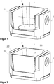
Die Erfindung wird nachfolgend anhand eines Ausführungsbeispiels näher erläutert, wobei gleiche oder ähnliche Merkmale mit denselben Bezugszeichen versehen sind. Dazu zeigen in schematischer Darstellung die
- Figur 1:
- eine Ausgestaltung des Arbeitstisches ohne Schottwand in Schrägdraufsicht,
- Figur 2:
- den Arbeitstisch mit eingesetzter Schottwand in Schrägdraufsicht;
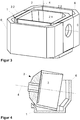
- Figur 3:
- den Arbeitstisch mit Bauraumaufnahme-Wanne in Schrägdraufsicht; und
- Figur 4:
- den Arbeitstisch mit gekipptem Bauraum im Querschnitt.
- FIG. 1:
- an embodiment of the work table without bulkhead in a diagonal top view,
- FIG. 2:
- the work table with inserted bulkhead in oblique top view;
- FIG. 3:
- the worktable with space receiving tub in oblique top view; and
- FIG. 4:
- the work table with tilted space in cross section.
Der Bauraum 2 ist, wie in
Der Bauraum 2 umfasst die Bauraum-Seitenwände 2.2 sowie die lösbare Schottwand 2.1, die, wie in
- 11
- Bauraumaufnahmespace recording
- 22
- Bauraumspace
- 2.12.1
- lösbare Bauraum-Seitenwand / Schottwanddetachable space sidewall / bulkhead
- 2.22.2
- Bauraum-SeitenwandSpace sidewall
- 33
- FertigungsunterlageManufacturing base
- 44
- Drehachseaxis of rotation
- 55
- Kippachsetilt axis
- 66
- Bauraumaufnahmen-SeitenwandSpace shots sidewall
Claims (14)
dadurch gekennzeichnet, dass
characterized in that
Applications Claiming Priority (1)
| Application Number | Priority Date | Filing Date | Title |
|---|---|---|---|
| DE102016106373.8A DE102016106373A1 (en) | 2016-04-07 | 2016-04-07 | Worktable for additive manufacturing |
Publications (2)
| Publication Number | Publication Date |
|---|---|
| EP3228407A1 true EP3228407A1 (en) | 2017-10-11 |
| EP3228407B1 EP3228407B1 (en) | 2019-01-09 |
Family
ID=58530382
Family Applications (1)
| Application Number | Title | Priority Date | Filing Date |
|---|---|---|---|
| EP17164906.4A Active EP3228407B1 (en) | 2016-04-07 | 2017-04-05 | Work table for additive manufacturing |
Country Status (3)
| Country | Link |
|---|---|
| EP (1) | EP3228407B1 (en) |
| DE (1) | DE102016106373A1 (en) |
| ES (1) | ES2718415T3 (en) |
Cited By (2)
| Publication number | Priority date | Publication date | Assignee | Title |
|---|---|---|---|---|
| CN107891148A (en) * | 2017-12-26 | 2018-04-10 | 大连三垒科技有限公司 | Turntable cooling device |
| CN109822092A (en) * | 2018-12-12 | 2019-05-31 | 上海航天设备制造总厂有限公司 | The powder increasing material manufacturing device and method thereof of the floated shaping substrate control in space |
Families Citing this family (2)
| Publication number | Priority date | Publication date | Assignee | Title |
|---|---|---|---|---|
| DE102018204191A1 (en) * | 2018-03-20 | 2019-09-26 | MTU Aero Engines AG | Device for the additive production of at least one component region of a component and layer construction method |
| DE102020004914A1 (en) | 2020-08-13 | 2022-02-17 | Helmut Nickolay | Machine for the production of metallic shaped bodies using additive manufacturing processes |
Citations (7)
| Publication number | Priority date | Publication date | Assignee | Title |
|---|---|---|---|---|
| US20070012256A1 (en) | 2005-07-12 | 2007-01-18 | Tecniplast S.P.A. | Basin capable of containing aquatic animals, especially experimental animals, and relating housing system |
| DE102007009273A1 (en) | 2007-02-26 | 2007-08-16 | Daimlerchrysler Ag | Production of a three-dimensional object using powder metallurgy comprises partially passing a fluid through a layer cake produced during the process |
| CN104525947A (en) | 2014-12-22 | 2015-04-22 | 江苏友诚数控科技有限公司 | Metal 3D printer |
| WO2015164502A1 (en) | 2014-04-22 | 2015-10-29 | Suarez Thomas William | 3d printer system having a rotatable platform, metal flake filament, multiple heaters, and modularity |
| WO2016019435A1 (en) * | 2014-08-05 | 2016-02-11 | Laing O'rourke Australia Pty Limited | Apparatus for fabricating an object |
| DE102015113792A1 (en) * | 2014-09-09 | 2016-03-10 | Siemens Energy, Inc. | Articulating construction platform for laser-based additive manufacturing |
| WO2017121995A1 (en) * | 2016-01-13 | 2017-07-20 | Renishaw Plc | Powder bed fusion apparatus and methods |
Family Cites Families (3)
| Publication number | Priority date | Publication date | Assignee | Title |
|---|---|---|---|---|
| DE10053741C1 (en) * | 2000-10-30 | 2002-02-21 | Concept Laser Gmbh | Machine for sintering, removing material from or marking surface with laser beam uses trolleys which include container for workpieces and have working platform whose height can be adjusted |
| US7326377B2 (en) | 2005-11-30 | 2008-02-05 | Honeywell International, Inc. | Solid-free-form fabrication process and apparatus including in-process workpiece cooling |
| JP5751118B2 (en) * | 2011-09-29 | 2015-07-22 | ブラザー工業株式会社 | 3D modeling equipment |
-
2016
- 2016-04-07 DE DE102016106373.8A patent/DE102016106373A1/en not_active Withdrawn
-
2017
- 2017-04-05 EP EP17164906.4A patent/EP3228407B1/en active Active
- 2017-04-05 ES ES17164906T patent/ES2718415T3/en active Active
Patent Citations (7)
| Publication number | Priority date | Publication date | Assignee | Title |
|---|---|---|---|---|
| US20070012256A1 (en) | 2005-07-12 | 2007-01-18 | Tecniplast S.P.A. | Basin capable of containing aquatic animals, especially experimental animals, and relating housing system |
| DE102007009273A1 (en) | 2007-02-26 | 2007-08-16 | Daimlerchrysler Ag | Production of a three-dimensional object using powder metallurgy comprises partially passing a fluid through a layer cake produced during the process |
| WO2015164502A1 (en) | 2014-04-22 | 2015-10-29 | Suarez Thomas William | 3d printer system having a rotatable platform, metal flake filament, multiple heaters, and modularity |
| WO2016019435A1 (en) * | 2014-08-05 | 2016-02-11 | Laing O'rourke Australia Pty Limited | Apparatus for fabricating an object |
| DE102015113792A1 (en) * | 2014-09-09 | 2016-03-10 | Siemens Energy, Inc. | Articulating construction platform for laser-based additive manufacturing |
| CN104525947A (en) | 2014-12-22 | 2015-04-22 | 江苏友诚数控科技有限公司 | Metal 3D printer |
| WO2017121995A1 (en) * | 2016-01-13 | 2017-07-20 | Renishaw Plc | Powder bed fusion apparatus and methods |
Cited By (2)
| Publication number | Priority date | Publication date | Assignee | Title |
|---|---|---|---|---|
| CN107891148A (en) * | 2017-12-26 | 2018-04-10 | 大连三垒科技有限公司 | Turntable cooling device |
| CN109822092A (en) * | 2018-12-12 | 2019-05-31 | 上海航天设备制造总厂有限公司 | The powder increasing material manufacturing device and method thereof of the floated shaping substrate control in space |
Also Published As
| Publication number | Publication date |
|---|---|
| ES2718415T3 (en) | 2019-07-01 |
| DE102016106373A1 (en) | 2017-10-12 |
| EP3228407B1 (en) | 2019-01-09 |
Similar Documents
| Publication | Publication Date | Title |
|---|---|---|
| EP3069816B1 (en) | Method and installation for additive manufacturing using a wire-shaped material | |
| EP3228407B1 (en) | Work table for additive manufacturing | |
| EP3393762B1 (en) | Method and device for producing 3d shaped parts using layering technology | |
| EP3222373B1 (en) | Method and installation for additive manufacturing of metallic moulded body | |
| DE102012012344B4 (en) | Method and device for the production of workpieces by jet melting of pulverulent material | |
| DE102007009273B4 (en) | Method and device for producing a three-dimensional article from a solidifiable material | |
| DE102006053121B3 (en) | Coating device for applying powdered layers to a device for producing a three-dimensional object comprises longitudinal walls joined together, a unit for fluidizing powdered material and a controlling and/or regulating unit | |
| EP1963078B1 (en) | Device and method for building up a three-dimensional object layer by layer | |
| EP3271156A1 (en) | Method and device for producing 3d shaped articles with a double recoater | |
| EP3349928B1 (en) | Method and apparatus for additive manufacturing | |
| EP3585592B1 (en) | Homogenisation of the energy input | |
| EP3069804B1 (en) | Method for additive production of a workpiece | |
| EP3579998B1 (en) | Increase in surface quality | |
| EP0502378A1 (en) | Apparatus and method to produce synthetic material skins and objects from plastic | |
| EP3318352A1 (en) | Method for simulation-based detection of thermally critical component areas and method for component-specific adaption of local heat generation during additive production | |
| EP3328619B1 (en) | Method and device for producing a three-dimensional object | |
| EP3458209B1 (en) | Method and device for overall temperature-control close to the mould cavity of temperature-controlled shell-type moulds, using intercommunicating media in polyhedral spaces | |
| DE102015108131A1 (en) | Method and apparatus for additive manufacturing | |
| DE102018003336A1 (en) | Arrangement and method for applying particulate building material in a 3D printer | |
| WO2020043419A1 (en) | Layering apparatus for the additive manufacture of at least one component region of a component, method for operating such a layering apparatus, and storage medium | |
| DE102018205689A1 (en) | Method and device for improving the component homogeneity of objects produced by an additive manufacturing method | |
| EP4065344A1 (en) | Method and apparatus for producing 3d shaped articles using high-performance radiation emitters | |
| EP3275337B1 (en) | Method and apparatus for forming a leveled surface of pasty masses | |
| DE102006044044A1 (en) | Method and device for producing a three-dimensional article from a solidifiable material | |
| EP3342508A1 (en) | Device for the generative production of workpieces |
Legal Events
| Date | Code | Title | Description |
|---|---|---|---|
| PUAI | Public reference made under article 153(3) epc to a published international application that has entered the european phase |
Free format text: ORIGINAL CODE: 0009012 |
|
| STAA | Information on the status of an ep patent application or granted ep patent |
Free format text: STATUS: THE APPLICATION HAS BEEN PUBLISHED |
|
| AK | Designated contracting states |
Kind code of ref document: A1 Designated state(s): AL AT BE BG CH CY CZ DE DK EE ES FI FR GB GR HR HU IE IS IT LI LT LU LV MC MK MT NL NO PL PT RO RS SE SI SK SM TR |
|
| AX | Request for extension of the european patent |
Extension state: BA ME |
|
| STAA | Information on the status of an ep patent application or granted ep patent |
Free format text: STATUS: REQUEST FOR EXAMINATION WAS MADE |
|
| 17P | Request for examination filed |
Effective date: 20171012 |
|
| RBV | Designated contracting states (corrected) |
Designated state(s): AL AT BE BG CH CY CZ DE DK EE ES FI FR GB GR HR HU IE IS IT LI LT LU LV MC MK MT NL NO PL PT RO RS SE SI SK SM TR |
|
| STAA | Information on the status of an ep patent application or granted ep patent |
Free format text: STATUS: EXAMINATION IS IN PROGRESS |
|
| 17Q | First examination report despatched |
Effective date: 20180215 |
|
| REG | Reference to a national code |
Ref country code: DE Ref legal event code: R079 Ref document number: 502017000632 Country of ref document: DE Free format text: PREVIOUS MAIN CLASS: B22F0003105000 Ipc: B23K0026342000 |
|
| RIC1 | Information provided on ipc code assigned before grant |
Ipc: B23K 26/342 20140101AFI20180516BHEP Ipc: B22F 3/105 20060101ALI20180516BHEP Ipc: B29C 64/245 20170101ALI20180516BHEP Ipc: B33Y 30/00 20150101ALI20180516BHEP Ipc: B29C 64/241 20170101ALI20180516BHEP |
|
| GRAP | Despatch of communication of intention to grant a patent |
Free format text: ORIGINAL CODE: EPIDOSNIGR1 |
|
| STAA | Information on the status of an ep patent application or granted ep patent |
Free format text: STATUS: GRANT OF PATENT IS INTENDED |
|
| INTG | Intention to grant announced |
Effective date: 20180731 |
|
| GRAS | Grant fee paid |
Free format text: ORIGINAL CODE: EPIDOSNIGR3 |
|
| GRAA | (expected) grant |
Free format text: ORIGINAL CODE: 0009210 |
|
| STAA | Information on the status of an ep patent application or granted ep patent |
Free format text: STATUS: THE PATENT HAS BEEN GRANTED |
|
| RIN1 | Information on inventor provided before grant (corrected) |
Inventor name: HASCHKE, IGOR Inventor name: FISCHER, GEORG Inventor name: DR. FUEHRER, MATTHIAS Inventor name: ROEHRICH, TOBIAS |
|
| AK | Designated contracting states |
Kind code of ref document: B1 Designated state(s): AL AT BE BG CH CY CZ DE DK EE ES FI FR GB GR HR HU IE IS IT LI LT LU LV MC MK MT NL NO PL PT RO RS SE SI SK SM TR |
|
| REG | Reference to a national code |
Ref country code: GB Ref legal event code: FG4D Free format text: NOT ENGLISH |
|
| REG | Reference to a national code |
Ref country code: CH Ref legal event code: EP Ref country code: AT Ref legal event code: REF Ref document number: 1086709 Country of ref document: AT Kind code of ref document: T Effective date: 20190115 |
|
| REG | Reference to a national code |
Ref country code: DE Ref legal event code: R096 Ref document number: 502017000632 Country of ref document: DE |
|
| REG | Reference to a national code |
Ref country code: IE Ref legal event code: FG4D Free format text: LANGUAGE OF EP DOCUMENT: GERMAN |
|
| REG | Reference to a national code |
Ref country code: NL Ref legal event code: FP |
|
| REG | Reference to a national code |
Ref country code: LT Ref legal event code: MG4D |
|
| REG | Reference to a national code |
Ref country code: ES Ref legal event code: FG2A Ref document number: 2718415 Country of ref document: ES Kind code of ref document: T3 Effective date: 20190701 |
|
| PG25 | Lapsed in a contracting state [announced via postgrant information from national office to epo] |
Ref country code: LT Free format text: LAPSE BECAUSE OF FAILURE TO SUBMIT A TRANSLATION OF THE DESCRIPTION OR TO PAY THE FEE WITHIN THE PRESCRIBED TIME-LIMIT Effective date: 20190109 Ref country code: FI Free format text: LAPSE BECAUSE OF FAILURE TO SUBMIT A TRANSLATION OF THE DESCRIPTION OR TO PAY THE FEE WITHIN THE PRESCRIBED TIME-LIMIT Effective date: 20190109 Ref country code: NO Free format text: LAPSE BECAUSE OF FAILURE TO SUBMIT A TRANSLATION OF THE DESCRIPTION OR TO PAY THE FEE WITHIN THE PRESCRIBED TIME-LIMIT Effective date: 20190409 Ref country code: PT Free format text: LAPSE BECAUSE OF FAILURE TO SUBMIT A TRANSLATION OF THE DESCRIPTION OR TO PAY THE FEE WITHIN THE PRESCRIBED TIME-LIMIT Effective date: 20190509 Ref country code: SE Free format text: LAPSE BECAUSE OF FAILURE TO SUBMIT A TRANSLATION OF THE DESCRIPTION OR TO PAY THE FEE WITHIN THE PRESCRIBED TIME-LIMIT Effective date: 20190109 |
|
| PGFP | Annual fee paid to national office [announced via postgrant information from national office to epo] |
Ref country code: ES Payment date: 20190520 Year of fee payment: 3 |
|
| PG25 | Lapsed in a contracting state [announced via postgrant information from national office to epo] |
Ref country code: GR Free format text: LAPSE BECAUSE OF FAILURE TO SUBMIT A TRANSLATION OF THE DESCRIPTION OR TO PAY THE FEE WITHIN THE PRESCRIBED TIME-LIMIT Effective date: 20190410 Ref country code: RS Free format text: LAPSE BECAUSE OF FAILURE TO SUBMIT A TRANSLATION OF THE DESCRIPTION OR TO PAY THE FEE WITHIN THE PRESCRIBED TIME-LIMIT Effective date: 20190109 Ref country code: HR Free format text: LAPSE BECAUSE OF FAILURE TO SUBMIT A TRANSLATION OF THE DESCRIPTION OR TO PAY THE FEE WITHIN THE PRESCRIBED TIME-LIMIT Effective date: 20190109 Ref country code: LV Free format text: LAPSE BECAUSE OF FAILURE TO SUBMIT A TRANSLATION OF THE DESCRIPTION OR TO PAY THE FEE WITHIN THE PRESCRIBED TIME-LIMIT Effective date: 20190109 Ref country code: IS Free format text: LAPSE BECAUSE OF FAILURE TO SUBMIT A TRANSLATION OF THE DESCRIPTION OR TO PAY THE FEE WITHIN THE PRESCRIBED TIME-LIMIT Effective date: 20190509 Ref country code: BG Free format text: LAPSE BECAUSE OF FAILURE TO SUBMIT A TRANSLATION OF THE DESCRIPTION OR TO PAY THE FEE WITHIN THE PRESCRIBED TIME-LIMIT Effective date: 20190409 |
|
| PGFP | Annual fee paid to national office [announced via postgrant information from national office to epo] |
Ref country code: BE Payment date: 20190418 Year of fee payment: 3 Ref country code: FR Payment date: 20190423 Year of fee payment: 3 |
|
| REG | Reference to a national code |
Ref country code: DE Ref legal event code: R097 Ref document number: 502017000632 Country of ref document: DE |
|
| PG25 | Lapsed in a contracting state [announced via postgrant information from national office to epo] |
Ref country code: AL Free format text: LAPSE BECAUSE OF FAILURE TO SUBMIT A TRANSLATION OF THE DESCRIPTION OR TO PAY THE FEE WITHIN THE PRESCRIBED TIME-LIMIT Effective date: 20190109 Ref country code: DK Free format text: LAPSE BECAUSE OF FAILURE TO SUBMIT A TRANSLATION OF THE DESCRIPTION OR TO PAY THE FEE WITHIN THE PRESCRIBED TIME-LIMIT Effective date: 20190109 Ref country code: EE Free format text: LAPSE BECAUSE OF FAILURE TO SUBMIT A TRANSLATION OF THE DESCRIPTION OR TO PAY THE FEE WITHIN THE PRESCRIBED TIME-LIMIT Effective date: 20190109 Ref country code: IT Free format text: LAPSE BECAUSE OF FAILURE TO SUBMIT A TRANSLATION OF THE DESCRIPTION OR TO PAY THE FEE WITHIN THE PRESCRIBED TIME-LIMIT Effective date: 20190109 Ref country code: SK Free format text: LAPSE BECAUSE OF FAILURE TO SUBMIT A TRANSLATION OF THE DESCRIPTION OR TO PAY THE FEE WITHIN THE PRESCRIBED TIME-LIMIT Effective date: 20190109 Ref country code: RO Free format text: LAPSE BECAUSE OF FAILURE TO SUBMIT A TRANSLATION OF THE DESCRIPTION OR TO PAY THE FEE WITHIN THE PRESCRIBED TIME-LIMIT Effective date: 20190109 Ref country code: CZ Free format text: LAPSE BECAUSE OF FAILURE TO SUBMIT A TRANSLATION OF THE DESCRIPTION OR TO PAY THE FEE WITHIN THE PRESCRIBED TIME-LIMIT Effective date: 20190109 |
|
| PLBE | No opposition filed within time limit |
Free format text: ORIGINAL CODE: 0009261 |
|
| STAA | Information on the status of an ep patent application or granted ep patent |
Free format text: STATUS: NO OPPOSITION FILED WITHIN TIME LIMIT |
|
| PG25 | Lapsed in a contracting state [announced via postgrant information from national office to epo] |
Ref country code: PL Free format text: LAPSE BECAUSE OF FAILURE TO SUBMIT A TRANSLATION OF THE DESCRIPTION OR TO PAY THE FEE WITHIN THE PRESCRIBED TIME-LIMIT Effective date: 20190109 |
|
| 26N | No opposition filed |
Effective date: 20191010 |
|
| PG25 | Lapsed in a contracting state [announced via postgrant information from national office to epo] |
Ref country code: LU Free format text: LAPSE BECAUSE OF NON-PAYMENT OF DUE FEES Effective date: 20190405 Ref country code: MC Free format text: LAPSE BECAUSE OF FAILURE TO SUBMIT A TRANSLATION OF THE DESCRIPTION OR TO PAY THE FEE WITHIN THE PRESCRIBED TIME-LIMIT Effective date: 20190109 |
|
| PG25 | Lapsed in a contracting state [announced via postgrant information from national office to epo] |
Ref country code: SI Free format text: LAPSE BECAUSE OF FAILURE TO SUBMIT A TRANSLATION OF THE DESCRIPTION OR TO PAY THE FEE WITHIN THE PRESCRIBED TIME-LIMIT Effective date: 20190109 |
|
| PG25 | Lapsed in a contracting state [announced via postgrant information from national office to epo] |
Ref country code: TR Free format text: LAPSE BECAUSE OF FAILURE TO SUBMIT A TRANSLATION OF THE DESCRIPTION OR TO PAY THE FEE WITHIN THE PRESCRIBED TIME-LIMIT Effective date: 20190109 |
|
| PG25 | Lapsed in a contracting state [announced via postgrant information from national office to epo] |
Ref country code: IE Free format text: LAPSE BECAUSE OF NON-PAYMENT OF DUE FEES Effective date: 20190405 |
|
| REG | Reference to a national code |
Ref country code: CH Ref legal event code: PL |
|
| REG | Reference to a national code |
Ref country code: NL Ref legal event code: MM Effective date: 20200501 |
|
| PG25 | Lapsed in a contracting state [announced via postgrant information from national office to epo] |
Ref country code: LI Free format text: LAPSE BECAUSE OF NON-PAYMENT OF DUE FEES Effective date: 20200430 Ref country code: CH Free format text: LAPSE BECAUSE OF NON-PAYMENT OF DUE FEES Effective date: 20200430 Ref country code: FR Free format text: LAPSE BECAUSE OF NON-PAYMENT OF DUE FEES Effective date: 20200430 |
|
| REG | Reference to a national code |
Ref country code: BE Ref legal event code: MM Effective date: 20200430 |
|
| PG25 | Lapsed in a contracting state [announced via postgrant information from national office to epo] |
Ref country code: BE Free format text: LAPSE BECAUSE OF NON-PAYMENT OF DUE FEES Effective date: 20200430 |
|
| PG25 | Lapsed in a contracting state [announced via postgrant information from national office to epo] |
Ref country code: NL Free format text: LAPSE BECAUSE OF NON-PAYMENT OF DUE FEES Effective date: 20200501 |
|
| PG25 | Lapsed in a contracting state [announced via postgrant information from national office to epo] |
Ref country code: CY Free format text: LAPSE BECAUSE OF FAILURE TO SUBMIT A TRANSLATION OF THE DESCRIPTION OR TO PAY THE FEE WITHIN THE PRESCRIBED TIME-LIMIT Effective date: 20190109 |
|
| PG25 | Lapsed in a contracting state [announced via postgrant information from national office to epo] |
Ref country code: SM Free format text: LAPSE BECAUSE OF FAILURE TO SUBMIT A TRANSLATION OF THE DESCRIPTION OR TO PAY THE FEE WITHIN THE PRESCRIBED TIME-LIMIT Effective date: 20190109 |
|
| PG25 | Lapsed in a contracting state [announced via postgrant information from national office to epo] |
Ref country code: MT Free format text: LAPSE BECAUSE OF FAILURE TO SUBMIT A TRANSLATION OF THE DESCRIPTION OR TO PAY THE FEE WITHIN THE PRESCRIBED TIME-LIMIT Effective date: 20190109 Ref country code: HU Free format text: LAPSE BECAUSE OF FAILURE TO SUBMIT A TRANSLATION OF THE DESCRIPTION OR TO PAY THE FEE WITHIN THE PRESCRIBED TIME-LIMIT; INVALID AB INITIO Effective date: 20170405 |
|
| REG | Reference to a national code |
Ref country code: ES Ref legal event code: FD2A Effective date: 20210826 |
|
| GBPC | Gb: european patent ceased through non-payment of renewal fee |
Effective date: 20210405 |
|
| PG25 | Lapsed in a contracting state [announced via postgrant information from national office to epo] |
Ref country code: GB Free format text: LAPSE BECAUSE OF NON-PAYMENT OF DUE FEES Effective date: 20210405 |
|
| REG | Reference to a national code |
Ref country code: DE Ref legal event code: R082 Ref document number: 502017000632 Country of ref document: DE Representative=s name: WERNER, ANDRE, DR., DE |
|
| PG25 | Lapsed in a contracting state [announced via postgrant information from national office to epo] |
Ref country code: MK Free format text: LAPSE BECAUSE OF FAILURE TO SUBMIT A TRANSLATION OF THE DESCRIPTION OR TO PAY THE FEE WITHIN THE PRESCRIBED TIME-LIMIT Effective date: 20190109 |
|
| PG25 | Lapsed in a contracting state [announced via postgrant information from national office to epo] |
Ref country code: ES Free format text: LAPSE BECAUSE OF NON-PAYMENT OF DUE FEES Effective date: 20200406 |
|
| P01 | Opt-out of the competence of the unified patent court (upc) registered |
Effective date: 20230403 |
|
| REG | Reference to a national code |
Ref country code: AT Ref legal event code: MM01 Ref document number: 1086709 Country of ref document: AT Kind code of ref document: T Effective date: 20220405 |
|
| PG25 | Lapsed in a contracting state [announced via postgrant information from national office to epo] |
Ref country code: AT Free format text: LAPSE BECAUSE OF NON-PAYMENT OF DUE FEES Effective date: 20220405 |
|
| PGFP | Annual fee paid to national office [announced via postgrant information from national office to epo] |
Ref country code: DE Payment date: 20230430 Year of fee payment: 7 |