EP3227825B1 - Inventarsystem für objekte in einem von einem gehäuse begrenzten raum sowie ein durch solch ein inventarsystem implementiertes inventarverfahren - Google Patents
Inventarsystem für objekte in einem von einem gehäuse begrenzten raum sowie ein durch solch ein inventarsystem implementiertes inventarverfahren Download PDFInfo
- Publication number
- EP3227825B1 EP3227825B1 EP15804434.7A EP15804434A EP3227825B1 EP 3227825 B1 EP3227825 B1 EP 3227825B1 EP 15804434 A EP15804434 A EP 15804434A EP 3227825 B1 EP3227825 B1 EP 3227825B1
- Authority
- EP
- European Patent Office
- Prior art keywords
- enclosure
- power variation
- objects
- inventorying
- variation model
- Prior art date
- Legal status (The legal status is an assumption and is not a legal conclusion. Google has not performed a legal analysis and makes no representation as to the accuracy of the status listed.)
- Active
Links
Images


Classifications
-
- G—PHYSICS
- G06—COMPUTING OR CALCULATING; COUNTING
- G06K—GRAPHICAL DATA READING; PRESENTATION OF DATA; RECORD CARRIERS; HANDLING RECORD CARRIERS
- G06K7/00—Methods or arrangements for sensing record carriers, e.g. for reading patterns
- G06K7/10—Methods or arrangements for sensing record carriers, e.g. for reading patterns by electromagnetic radiation, e.g. optical sensing; by corpuscular radiation
- G06K7/10009—Methods or arrangements for sensing record carriers, e.g. for reading patterns by electromagnetic radiation, e.g. optical sensing; by corpuscular radiation sensing by radiation using wavelengths larger than 0.1 mm, e.g. radio-waves or microwaves
- G06K7/10198—Methods or arrangements for sensing record carriers, e.g. for reading patterns by electromagnetic radiation, e.g. optical sensing; by corpuscular radiation sensing by radiation using wavelengths larger than 0.1 mm, e.g. radio-waves or microwaves setting parameters for the interrogator, e.g. programming parameters and operating modes
- G06K7/10217—Methods or arrangements for sensing record carriers, e.g. for reading patterns by electromagnetic radiation, e.g. optical sensing; by corpuscular radiation sensing by radiation using wavelengths larger than 0.1 mm, e.g. radio-waves or microwaves setting parameters for the interrogator, e.g. programming parameters and operating modes parameter settings controlling the transmission power of the interrogator
-
- G—PHYSICS
- G06—COMPUTING OR CALCULATING; COUNTING
- G06Q—INFORMATION AND COMMUNICATION TECHNOLOGY [ICT] SPECIALLY ADAPTED FOR ADMINISTRATIVE, COMMERCIAL, FINANCIAL, MANAGERIAL OR SUPERVISORY PURPOSES; SYSTEMS OR METHODS SPECIALLY ADAPTED FOR ADMINISTRATIVE, COMMERCIAL, FINANCIAL, MANAGERIAL OR SUPERVISORY PURPOSES, NOT OTHERWISE PROVIDED FOR
- G06Q10/00—Administration; Management
- G06Q10/08—Logistics, e.g. warehousing, loading or distribution; Inventory or stock management
- G06Q10/087—Inventory or stock management, e.g. order filling, procurement or balancing against orders
- G06Q10/0875—Itemisation or classification of parts, supplies or services, e.g. bill of materials
-
- B—PERFORMING OPERATIONS; TRANSPORTING
- B60—VEHICLES IN GENERAL
- B60R—VEHICLES, VEHICLE FITTINGS, OR VEHICLE PARTS, NOT OTHERWISE PROVIDED FOR
- B60R2325/00—Indexing scheme relating to vehicle anti-theft devices
- B60R2325/10—Communication protocols, communication systems of vehicle anti-theft devices
- B60R2325/105—Radio frequency identification data [RFID]
-
- G—PHYSICS
- G06—COMPUTING OR CALCULATING; COUNTING
- G06K—GRAPHICAL DATA READING; PRESENTATION OF DATA; RECORD CARRIERS; HANDLING RECORD CARRIERS
- G06K7/00—Methods or arrangements for sensing record carriers, e.g. for reading patterns
Definitions
- the present invention relates to a system for inventorying objects contained in a space limited by an enclosure using radio frequency identification (RFID) technology as well as an inventory method implemented by such an inventory system.
- RFID radio frequency identification
- the reading point emits a modulated electromagnetic wave, called a wake-up wave, to each tag in the system.
- a tag located in a coverage area where the electromagnetic field generated by the reading point is at a sufficiently high level, comes out of its standby state, becomes active and then emits identification data specific to it in the form of a modulated electromagnetic wave.
- This identification data is received by the reading point which then proceeds to identify the tag in question.
- the coverage area is generally between 0 and 7 meters in the direction of electromagnetic radiation of the antenna of the reading point. The latter can be provided with several antennas to increase the volume of the coverage area of the reading point.
- each tag is attached to an object, such as a tool used for the maintenance of a workshop, a factory, etc.
- the objects to be inventoried are stored in a space, such as a piece of furniture, a trolley, a cupboard with or without shelves, drawers, etc.
- a space such as a piece of furniture, a trolley, a cupboard with or without shelves, drawers, etc.
- this space is made hermetic to the electromagnetic waves emitted by the reading point, for example by delimiting it with a metal enclosure.
- the tags inside this enclosure emit their identification data. Therefore, only the objects stored in the enclosure are taken into account at the time of the inventory.
- This type of inventory system faces problems. Any object placed in the enclosure but also the walls of the enclosure can act as reflectors for the electromagnetic waves emitted by the antenna(s) of the reading point. Thus, direct waves and reflected waves can interfere with each other and create maxima but also minima of power in the enclosure. If a tag is located at a minima, the power of the electromagnetic wake-up wave it receives may be insufficient to make it active. It then does not emit its identification data and the reading point cannot therefore identify it. The inventory is incorrect.
- the objects to be inventoried themselves reflect the incident waves, for example because they are metallic, which is generally the case for tools, they can further increase the interference phenomenon described above.
- the interference thus created and therefore the topology of the power minima and maxima created are themselves a function of the presence or absence of the objects in the enclosure. This topology can vary from one inventory to another.
- the method proposed above is highly dependent on the objects, particularly metallic ones, contained in the storage enclosure.
- the presence or absence of metallic objects in the volume therefore modifies the distribution of electromagnetic fields and therefore the quality of the identification.
- the aim of the present invention is to provide a system for inventorying objects contained in a metal enclosure which is such that it overcomes the interference problems mentioned above.
- the present invention relates to a system for inventorying objects contained in a space delimited by an enclosure, according to claim 1.
- said inventory system comprises reference beacons placed at fixed locations in said enclosure, said reading point being provided for, on the basis of the identification data received from the reference beacons, establishing a map of the active reference beacons, with each power variation model established during the learning phase for each particular configuration of the enclosure and the objects it contains being associated with a map of the active reference beacons, the power variation model used to carry out said inventory being that which is associated with the map of the active reference beacons for the operating configuration of the enclosure and the objects it contains at the time of said inventory.
- said means for controlling the emission power of said electromagnetic wave of wake-up by said or each antenna are made up of a control unit directly controlling said reading point to do so.
- said means for controlling the transmission power of said electromagnetic wake-up wave by said or each antenna comprise a power control unit interfacing between the antenna output(s) of said reading point and said antenna(s).
- the present invention also relates to a method of inventorying objects contained in a space delimited by an enclosure, according to claim 5.
- said method comprises a learning phase during which a power variation model is established for each particular configuration of the enclosure and the objects it contains, said power variation model used to carry out said inventory being that corresponding to the operating configuration of the enclosure and the objects it contains.
- said learning phase comprises a step of selecting, from a set of predetermined power variation models, the power variation model which, for the configuration of the enclosure and the objects it contains, gives the reading rate optimal compared to other power variation models of said set of models.
- said learning phase includes a step of determining the optimal duration of the selected model.
- said learning phase includes a step of verifying the repeatability of the inventory method for each of the selected and optimized power variation models.
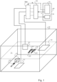
- the inventory system shown in the Fig. 1 is intended to inventory objects that are contained in a space such as a piece of furniture, a cupboard or a workshop trolley, which may contain elements, such as shelves, in this case, for example, the shelf 11, drawers, lockers, etc.
- a space such as a piece of furniture, a cupboard or a workshop trolley, which may contain elements, such as shelves, in this case, for example, the shelf 11, drawers, lockers, etc.
- This space is delimited by an enclosure 10.
- this enclosure 10 has been shown to be parallelepipedal, the invention is not limited to this particular shape.
- the objects in question are, for example, tools (of generic reference 20) for ensuring the maintenance of a workshop, a factory, etc., such as the mallet 21 and the keys 22 and 23 shown, which are each provided with a 20T RFID tag (Radio Frequency IDentification), in this case the tags 21T, 22T and 23T.
- tools for example, tools (of generic reference 20) for ensuring the maintenance of a workshop, a factory, etc., such as the mallet 21 and the keys 22 and 23 shown, which are each provided with a 20T RFID tag (Radio Frequency IDentification), in this case the tags 21T, 22T and 23T.
- 20T RFID tag Radio Frequency IDentification
- the inventory system further comprises a reading point 30 provided with at least one antenna (here three antennas 31, 32, and 33 respectively on the lower wall, the back wall and the shelf 11 of the enclosure 10) oriented so as to emit inside the enclosure 10.
- the antenna(s) 31, 32 and 33 are positioned so that, taking into account the properties of the walls of the enclosure 10, such as their reflection or their absorption of the electromagnetic waves considered, the electromagnetic waves that they emit are confined inside said enclosure 10 and are no longer present outside said enclosure 10.
- the reading point 30 is for example connected to a processing system 40, such as a computer system or a computer, which comprises a control unit 41 for controlling the reading point 30 for its transmission and a processing unit 42 for in particular receiving from said reading point 30 data, for example identification data of the tags 20T contained in the enclosure 10, according to a specific application.
- a processing system 40 such as a computer system or a computer, which comprises a control unit 41 for controlling the reading point 30 for its transmission and a processing unit 42 for in particular receiving from said reading point 30 data, for example identification data of the tags 20T contained in the enclosure 10, according to a specific application.
- the operating principle of such an RFID system is as follows.
- the reading point 30 emits, by means of its antenna(s) 31, 32 and 33, a modulated electromagnetic wave, called a wake-up wave, intended for each tag 20 of the system (here, the tags 21T, 22T and 23T).
- a tag 20T located in a coverage area where the electromagnetic field generated by the antennas 31, 32 and 33 of the reading point 30 is at a sufficiently high level, comes out of its standby state and thus becomes active. It then emits identification data specific to it in the form of a modulated electromagnetic wave.
- This data identification is received by the reading point 30 which, for example, transmits it to the processing unit 42 of the processing system 40 for further processing in accordance with an application of said system 40.
- control unit 41 is provided to control the transmission power of said electromagnetic wake-up wave emitted by the or each antenna 31, 32, 33 of the reading point 30 so that this power conforms to a power variation model among a set of previously determined power variation models, each power variation model being linked to a particular configuration of the enclosure 10 and the objects 20 that said enclosure 10 is supposed to contain at the time of the inventory.
- control unit 41 directly controls the reading point 30 (arrow A) so that its antennas 31, 32 and 33 respectively emit electromagnetic wake-up waves according to a given power variation model.
- control unit 41 is a software unit of the processing system 40.
- the control unit 41 controls (arrow B) a power control unit 30bis so that the antennas 31, 32 and 33 respectively emit electromagnetic wake-up waves according to a given power variation model.
- the power control unit 30bis is advantageously a hardware unit which provides the interface between the antenna outputs of the reading point 30 and the antennas 31, 32 and 33. It is for example made up of variable gain amplifiers (not shown) themselves controlled by signals conforming to the power variation model selected by the control unit 41.
- the control unit 41 also controls the reading point 30, either so that its antenna outputs are of constant power, or so that its antenna outputs also follow a power variation model.
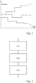
- a power variation model of the electromagnetic waves emitted by the antennas 31, 32, 33 of said reading point 30 is defined by a series of emissions by the or each antenna (here 31, 32 and 33) according to steps at different power levels from one step to another and from one antenna to another, if there are several antennas.
- Fig. 2 we see three curves, corresponding respectively to three different power variation models, comprising different power and duration steps for respectively the three antennas 31, 32 and 33 of the inventory system of the Fig. 1 . While for antenna 31, the power level transmission power level increases at each step, for antenna 32 it remains constant then decreases at the next step and then increases at the last step. For the third antenna 33 the transmission power level decreases at each step.
- An inventory system according to the present invention is intended to operate, first in a learning phase and then, subsequently, in an operating phase.
- a power variation model is determined which is optimized for a particular configuration of the enclosure 10 and the objects 20 (provided with their tags) which is the object of the learning.
- a configuration of the enclosure 10 is defined by the presence or absence of a shelf, a drawer, a locker, etc. in the piece of furniture that constitutes the enclosure.
- a configuration of the objects 20 is defined by a number of objects, of a particular type, for example: mallet, flat key, Allen key, screwdriver, etc. placed in particular locations of the enclosure 10.
- the power variation model that is optimized for a particular configuration of the enclosure 10 and the objects 20 is first selected from a set of predetermined models as the one that gives the best reading rate for the configuration of the enclosure and the objects considered and is then optimized by determining an optimal reading duration. It is also the one that allows repeatability of the inventory carried out for this configuration.
- the reading rate is the ratio of the number of 20T tags read by reading point 30 to the number of 20T tags present in enclosure 10.
- the optimal reading duration is the duration beyond which the number of tags read no longer increases significantly even if reading continues for a long time.
- the inventory repeatability of a given power model is obtained when, for a particular configuration, the number of tags read is identical or almost identical for a given number of repeated inventories, for example 10.
- the power variation model that was determined and optimized for the particular configuration of the enclosure 10 and the objects 20 during the learning phase is used to carry out inventories.
- This processing of step E300 may consist of listing all the objects which are present in the piece of furniture which constitutes the enclosure 10. This processing also allows the user to view the result of the inventory.
- Step E100 is for example implemented by the control unit 41 of the processing system 40.
- Steps E200 and E300 are for example implemented by the processing unit 42.
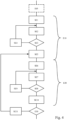
- Fig. 4 a diagram showing the different steps implemented by an inventory method during its learning phase. It includes a step E10 of selecting, from a predetermined set of power variation models M 1 to M N , the optimized power variation model which, for the configuration of the enclosure 10 and the objects 20 considered, gives the optimal reading rate compared to the other power variation models of said set of models.
- a step E05 determines the set of power variation models from which step E10 selects the optimized power variation model. For example, step 05 consists in determining the number of tags 20 read by the reading point 30 during a standard inventory M S carried out at constant power for a standard time ts. If this number is low, the set of models determined in step 05 will contain models with high power variations and in a fairly high number. On the other hand, if this number is high, the set of models determined in step 05 will contain models with low power variations and in a fairly low number.
- Said learning phase may also include a step E20 for determining the optimal duration t opt of the power variation model M max selected in substep SE5.
- This optimal duration t opt is the duration beyond which the number of tags read no longer increases significantly. It may also be less than a maximum duration t Max even if the number of tags read increases significantly over time. This maximum duration t Max is for example configurable by the user, according to his wishes.
- Step E30 for verifying the repeatability of the inventory method for the selected power variation model M max implemented during the optimized duration t opt .
- a substep SE31 is implemented for removing the model M max considered from the list of models present in substep SE5, which is again implemented to select from this truncated list the power variation model which now gives the highest reading rate.
- Steps E20 and E30 are again implemented with this new model M max .
- the learning phase is triggered when the inventory system is first started up or, at the user's request.
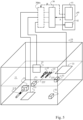
- the inventory system shown in the Fig. 5 is identical to that of the Fig. 1 except that it further comprises reference tags 50 (in this case, 51, 52 and 53) which are placed at fixed locations inside said enclosure 10.
- reference tags 50 are tags which are, for example, fixed on the inner face of the walls of the enclosure 10 or on fixed elements thereof, such as lockers, shelves, drawers contained in the enclosure 10.
- the identification data of these tags are specific so that the reading point 30 can differentiate them from the tags of the objects to be inventoried.
- the reference tags 50 which are located in a coverage area where the electromagnetic field generated by the antennas 31, 32 and 33 of the reading point 30 is at a sufficiently high level are activated and then emit their own identification data, the other tags not receiving an electromagnetic field of sufficient level, not being activated.
- the reading point 30 is then able to establish a map of the reference tags 50 which are active, that is to say which have responded to the electromagnetic wake-up wave emitted by the reading point 30.
- the inventory system of the Fig. 5 is intended to operate, first in a learning phase and then, subsequently, in an operating phase.
- the power variation model M P selected in step E160 from a set of predetermined power variation models can be selected based on the number of tags read during a standard inventory I(Ms, ts), like step E05 of the first embodiment.
- said learning phase may also include a step E30 of verifying the repeatability of the inventory process for the optimized model M Sm and a step E20 of determining the optimal duration t opt of the selected model M Sm .
- Step E30 may be repeated for the optimized model M Sm for the optimal duration t opt .
- step E'100 of triggering the execution of the power variation model which was selected in step E90 and steps E200 and E300 identical to those described previously and which, therefore, are not described again.
Landscapes
- Business, Economics & Management (AREA)
- Engineering & Computer Science (AREA)
- Physics & Mathematics (AREA)
- Economics (AREA)
- General Physics & Mathematics (AREA)
- Theoretical Computer Science (AREA)
- Toxicology (AREA)
- Health & Medical Sciences (AREA)
- Operations Research (AREA)
- Entrepreneurship & Innovation (AREA)
- General Business, Economics & Management (AREA)
- Accounting & Taxation (AREA)
- Finance (AREA)
- Development Economics (AREA)
- Tourism & Hospitality (AREA)
- Strategic Management (AREA)
- Human Resources & Organizations (AREA)
- Marketing (AREA)
- Quality & Reliability (AREA)
- Electromagnetism (AREA)
- Computer Vision & Pattern Recognition (AREA)
- General Health & Medical Sciences (AREA)
- Artificial Intelligence (AREA)
- Warehouses Or Storage Devices (AREA)
Claims (10)
- Inventarisierungssystem von in einem von einem Gehäuse (10) begrenzten Raum enthaltenen Objekten, wobei das System ein an jedem der zu inventarisierenden Objekte (20) befestigtes Tag (20T) und einen Lesepunkt (30) enthält, der mit mindestens einer Antenne (31, 32, 33) versehen ist, um eine auf das Innere des Gehäuses (10) beschränkte elektromagnetische Weckwelle zu emittieren, damit ein Tag (20T) bei ihrem Empfang aktiv wird und dann seine Identifikationsdaten an den Lesepunkt (30) sendet, der Lesepunkt (30) weist Einrichtungen (41, 42) auf, um die Emissionsleistung der elektromagnetischen Weckwelle entsprechend einem Leistungsänderungsmodell zu steuern, das von einer Folge von Emissionen durch die oder jede Antenne (31, 32, 33) gemäß Stufen auf von einer Stufe zu einer anderen unterschiedlichen Leistungspegeln definiert wird, um die Inventarisierung durchzuführen, wobei der Lesepunkt (30) vorgesehen ist, um in einem Lernmodus zu arbeiten, bei dem ein Leistungsänderungsmodell für jede bestimmte Konfiguration des Gehäuses (10) und der in ihm enthaltenen Objekte (20) erstellt wird, wobei das Leistungsänderungsmodell, das verwendet wird, um die Inventarisierung durchzuführen, dasjenige ist, das der Betriebskonfiguration des Gehäuses (10) und der in ihm enthaltenen Objekte (20) entspricht, und das Leistungsänderungsmodell durch Auswahl aus einer Gruppe von vorbestimmten Leistungsänderungsmodellen erstellt wird, wobei das ausgewählte Leistungsänderungsmodell dasjenige ist, das für die Betriebskonfiguration des betroffenen Gehäuses (10) und der Objekte (20) optimiert wird.
- Inventarisierungssystem nach Anspruch 1, dadurch gekennzeichnet, dass es Bezugsmarker (50) aufweist, die an ortsfesten Stellen im Gehäuse (10) platziert sind, dass der Lesepunkt (30) vorgesehen ist, um auf der Basis von von den Bezugsmarkern (50) empfangenen Identifikationsdaten eine Karte der aktiven Bezugsmarker zu erstellen, dass jedem Leistungsänderungsmodell, das in der Lernphase für jede bestimmte Konfiguration des Gehäuses (10) und der in ihm enthaltenen Objekte (20) erstellt wird, eine Karte der aktiven Bezugsmarker zugeordnet wird, und dass das Leistungsänderungsmodell, das verwendet wird, um die Inventarisierung durchzuführen, dasjenige ist, das der Karte der aktiven Bezugsmarker (50) für die Betriebskonfiguration des Gehäuses (10) und der in ihm enthaltenen Objekte (20) zum Zeitpunkt der Inventarisierung zugeordnet ist.
- Inventarisierungssystem nach einem der vorhergehenden Ansprüche, dadurch gekennzeichnet, dass die Einrichtungen, um die Emissionsleistung der elektromagnetischen Weckwelle durch die oder jede Antenne zu steuern, aus einer Steuereinheit (41) bestehen, die hierzu direkt den Lesepunkt (40) steuert.
- Inventarisierungssystem nach einem der vorhergehenden Ansprüche, dadurch gekennzeichnet, dass die Einrichtungen, um die Emissionsleistung der elektromagnetischen Weckwelle durch die oder jede Antenne zu steuern, eine Leistungskontrolleinheit (30bis) enthalten, die die Schnittstelle zwischen dem oder den Antennenausgängen des Lesepunkts (30) und der oder den Antennen (31, 32, 33) bildet.
- Inventarisierungsverfahren von in einem von einem Gehäuse (10) begrenzten Raum enthaltenen Objekten (20) mittels eines Inventarisierungssystems, das ein an jedem der Objekte befestigtes Tag und einen Lesepunkt (30) enthält, der mit mindestens einer Antenne (31, 32, 33) versehen ist, um eine auf das Innere des Gehäuses (10) beschränkte elektromagnetische Weckwelle zu emittieren, damit ein Tag (20T) bei ihrem Empfang aktiv wird und dann seine Identifikationsdaten an den Lesepunkt (30) sendet, wobei der Lesepunkt (30) vorgesehen ist, um in einem Lernmodus zu arbeiten, bei dem ein Leistungsänderungsmodell für jede bestimmte Konfiguration des Gehäuses (10) und der in ihm enthaltenen Objekte (20) erstellt wird, wobei das Leistungsänderungsmodell, das verwendet wird, um die Inventarisierung durchzuführen, dasjenige ist, das der Betriebskonfiguration des Gehäuses (10) und der in ihm enthaltenen Objekte (20) entspricht, und das Verfahren die folgenden vom Lesepunkt durchgeführten Schritte aufweist,- einen Schritt (E100) der Auswahl eines durch eine Folge von Emissionen durch die oder jede Antenne gemäß Stufen auf von einer Stufe zu einer anderen unterschiedlichen Leistungspegeln definierten Leistungsänderungsmodells, und des Auslösens der Ausführung des ausgewählten Leistungsänderungsmodells, und das Leistungsänderungsmodell wird durch Auswahl aus einer Gruppe von vorbestimmten Leistungsänderungsmodellen erstellt, wobei das ausgewählte Leistungsänderungsmodell dasjenige ist, das für die Betriebskonfiguration des betroffenen Gehäuses (10) und der Objekte (20) optimiert ist,- einen Schritt (E200) des Lesens der Identifikationsdaten, die von den Tags nach ihrer Aktivierung bei Empfang der verschiedenen elektromagnetischen Weckwellen gesendet werden, die von der oder den Antennen während der Ausführung des Leistungsänderungsmodells emittiert werden, und- einen Schritt (E300) der Verarbeitung der bei der Folge von Emissionen empfangenen Identifikationsdaten.
- Inventarisierungsverfahren nach Anspruch 5, dadurch gekennzeichnet, dass das Verfahren die Lernphase aufweist, während der ein Leistungsänderungsmodell für jede bestimmte Konfiguration des Gehäuses (10) und der in ihm enthaltenen Objekte (20) erstellt wird, wobei das Leistungsänderungsmodell, das verwendet wird, um die Inventarisierung durchzuführen, dasjenige ist, das der Betriebskonfiguration des Gehäuses und der in ihm enthaltenen Objekte entspricht.
- Inventarisierungsverfahren nach Anspruch 6, dadurch gekennzeichnet, dass die Lernphase einen Schritt (E10) der Auswahl, aus einer Gruppe von vorbestimmten Leistungsänderungsmodellen, des Leistungsänderungsmodells aufweist, das für die Konfiguration des Gehäuses und der in ihm enthaltenen Objekte die optimale Leserate bezüglich der anderen Leistungsänderungsmodelle der Gruppe von Modellen ergibt.
- Inventarisierungsverfahren nach Anspruch 7, dadurch gekennzeichnet, dass die Lernphase die folgenden Schritte aufweist:- einen Schritt (E15) des Erstellens einer Karte von aktiven Bezugsmarkern, und- einen Schritt (E16) der Bestimmung der Parameter eines Leistungsänderungsmodells, das eine höhere Leserate als eine Schwellenrate ergibt.
- Inventarisierungsverfahren nach Anspruch 7 oder 8, dadurch gekennzeichnet, dass die Lernphase einen Schritt (E20) der Bestimmung der optimalen Dauer des ausgewählten Modells aufweist.
- Inventarisierungsverfahren nach einem der Ansprüche 7 bis 9, dadurch gekennzeichnet, dass die Lernphase mindestens einen Schritt (E30) der Überprüfung der Wiederholbarkeit des Inventarisierungsverfahrens für jedes der ausgewählten und optimierten Leistungsänderungsmodelle aufweist.
Applications Claiming Priority (2)
| Application Number | Priority Date | Filing Date | Title |
|---|---|---|---|
| FR1461814A FR3029319B1 (fr) | 2014-12-02 | 2014-12-02 | Systeme d'inventaire d'objets contenus dans un espace limite par une enceinte ainsi qu'un procede d'inventaire mis en œuvre par un tel systeme d'inventaire |
| PCT/EP2015/078331 WO2016087502A1 (fr) | 2014-12-02 | 2015-12-02 | Système d'inventaire d'objets contenus dans un espace limité par une enceinte ainsi qu'un procédé d'inventaire mis en œuvre par un tel système d'inventaire |
Publications (4)
| Publication Number | Publication Date |
|---|---|
| EP3227825A1 EP3227825A1 (de) | 2017-10-11 |
| EP3227825B1 true EP3227825B1 (de) | 2024-11-13 |
| EP3227825C0 EP3227825C0 (de) | 2024-11-13 |
| EP3227825B8 EP3227825B8 (de) | 2024-12-18 |
Family
ID=53008587
Family Applications (1)
| Application Number | Title | Priority Date | Filing Date |
|---|---|---|---|
| EP15804434.7A Active EP3227825B8 (de) | 2014-12-02 | 2015-12-02 | Inventarsystem für objekte in einem von einem gehäuse begrenzten raum sowie ein durch solch ein inventarsystem implementiertes inventarverfahren |
Country Status (5)
| Country | Link |
|---|---|
| US (1) | US10489619B2 (de) |
| EP (1) | EP3227825B8 (de) |
| ES (1) | ES2996225T3 (de) |
| FR (1) | FR3029319B1 (de) |
| WO (1) | WO2016087502A1 (de) |
Families Citing this family (5)
| Publication number | Priority date | Publication date | Assignee | Title |
|---|---|---|---|---|
| FR3071643B1 (fr) * | 2017-09-27 | 2021-02-19 | Nexess | Systeme d'inventaire d'objets contenus dans un espace limite par une enceinte |
| WO2019094683A1 (en) | 2017-11-09 | 2019-05-16 | Gramercy Extremity Orthopedics, Llc | Surgical product supply system and method |
| FR3097354B1 (fr) | 2019-06-13 | 2021-06-04 | Gsp Tech Sarl | Boite de rangement adaptée pour procéder à un inventaire d’objets rangés dans la boite au moyen d’un système RFID. |
| CN111929636B (zh) * | 2020-06-16 | 2024-03-26 | 宜宾电子科技大学研究院 | 一种金属容器智能识别与标记定位方法 |
| CN114781981A (zh) * | 2022-06-17 | 2022-07-22 | 北京京东振世信息技术有限公司 | 库存确定方法、装置、电子设备和计算机可读介质 |
Family Cites Families (10)
| Publication number | Priority date | Publication date | Assignee | Title |
|---|---|---|---|---|
| JP4726037B2 (ja) * | 2004-01-20 | 2011-07-20 | オムロンオートモーティブエレクトロニクス株式会社 | トランスポンダの起動制御方法及びタイヤ状態監視システム用インタロゲータ |
| US20050280508A1 (en) * | 2004-02-24 | 2005-12-22 | Jim Mravca | System and method for controlling range of successful interrogation by RFID interrogation device |
| JP2006067160A (ja) | 2004-08-26 | 2006-03-09 | Fujitsu Ltd | 無線タグシステム、無線タグアクセス制御装置、無線タグアクセス制御方法、無線タグアクセス制御プログラム、及び無線タグ |
| US20060176152A1 (en) | 2005-02-10 | 2006-08-10 | Psc Scanning, Inc. | RFID power ramping for tag singulation |
| US7830262B1 (en) | 2006-04-25 | 2010-11-09 | Impinj, Inc. | Adjusting communication parameters while inventorying RFID tags |
| US8421627B2 (en) * | 2008-08-21 | 2013-04-16 | Symbol Technologies, Inc. | Method for associating and RFID tag with a known region |
| US20100201520A1 (en) * | 2009-02-12 | 2010-08-12 | Symbol Technologies, Inc. | System for determining item location based on feedback from fixed radio frequency identification (rfid) readers and/or fixed rfid beacon tags |
| US8786440B2 (en) * | 2009-10-02 | 2014-07-22 | Checkpoint Systems, Inc. | Calibration of beamforming nodes in a configurable monitoring device system |
| US8681001B2 (en) * | 2011-10-26 | 2014-03-25 | Motorola Solutions, Inc. | Method and apparatus for optimizing reader power consumption by varying poll parameters in an automated inventory tracking system |
| EP2939182A4 (de) * | 2012-12-29 | 2016-08-17 | Meps Real Time Inc | System und verfahren zur optimierung der identifizierung von mit rfid-etiketten gekennzeichneten artikeln in einem geschlossenen abgeschirmten raume |
-
2014
- 2014-12-02 FR FR1461814A patent/FR3029319B1/fr active Active
-
2015
- 2015-12-02 ES ES15804434T patent/ES2996225T3/es active Active
- 2015-12-02 EP EP15804434.7A patent/EP3227825B8/de active Active
- 2015-12-02 WO PCT/EP2015/078331 patent/WO2016087502A1/fr not_active Ceased
- 2015-12-02 US US15/532,310 patent/US10489619B2/en active Active
Also Published As
| Publication number | Publication date |
|---|---|
| US20170330001A1 (en) | 2017-11-16 |
| ES2996225T3 (en) | 2025-02-12 |
| EP3227825A1 (de) | 2017-10-11 |
| EP3227825B8 (de) | 2024-12-18 |
| WO2016087502A1 (fr) | 2016-06-09 |
| FR3029319A1 (fr) | 2016-06-03 |
| FR3029319B1 (fr) | 2018-01-19 |
| US10489619B2 (en) | 2019-11-26 |
| EP3227825C0 (de) | 2024-11-13 |
Similar Documents
| Publication | Publication Date | Title |
|---|---|---|
| EP3227825B1 (de) | Inventarsystem für objekte in einem von einem gehäuse begrenzten raum sowie ein durch solch ein inventarsystem implementiertes inventarverfahren | |
| EP2299288B1 (de) | Verfahren und System zur Lokalisierung einer Person, Aufzeichnungsträger für dieses Verfahren | |
| EP3035715B1 (de) | Verfahren zur annäherungsangabe und entsprechende einrichtung, programm, und speicher medium | |
| JP7453159B2 (ja) | 媒体内の受信機の特性を決定するための方法およびこの方法を実現するシステム | |
| EP2199966A1 (de) | Verfahren zur Sicherung von Transaktionen, entsprechende Transaktionsvorrichtung, entsprechender Bankserver, entsprechendes mobiles Endgerät und dazugehörige Computerprogrammprodukte | |
| FR2964289A1 (fr) | Procede et dispositif de localisation d'au moins un obstacle dans un reseau de communication, programme d'ordinateur correspondant. | |
| EP3444690B1 (de) | Kontrollsystem eines tragbaren werkzeugs mit autonomer energiequelle, tragbares werkzeug, entsprechendes modul und kontrollverfahren | |
| EP1429300A1 (de) | Verfahren zur Lokalisierung eines tragbaren Elements in einem handfreien Sicherungssystem, und entsprechendes handfreies Sicherungssystem | |
| WO2018215415A1 (fr) | Dispositif de mise en forme d'onde et récepteur d'onde | |
| EP3931739B1 (de) | System zur detektion von empfängern | |
| EP1153369B1 (de) | Verfahren zur detektion von tragbaren objekten und durchführungsystem | |
| EP1576430B1 (de) | Verfahren um eines netzwerkes zu konfigurieren | |
| EP3722989B1 (de) | Steuerungsverfahren des inhalts einer präsentationsvitrine mit produkten, die mit rfid-etiketten ausgestattet sind | |
| FR3096468A1 (fr) | Procédé de détermination d’au moins un emplacement pour la rétrodiffusion d’un signal ambiant | |
| EP4078231B1 (de) | Verfahren und system zur automatischen lokalisierung mittels radioelektrischer signale, entsprechendes programm und programmmedium | |
| EP3038396B1 (de) | Leitplanke mit mehreren kommunikationsschnittstellen mit gesicherter deaktivierung/reaktivierung | |
| EP3688658B1 (de) | Bestandsverwaltungssystem für gegenstände in einem raum, der durch eine kammer begrenzt ist | |
| EP2151697B1 (de) | Verfahren und System zur Lokalisierung eines mobilen kommunizierenden Gegenstands | |
| Zhu et al. | Combined optimisation of waveform and quantisation thresholds for multistatic radar systems | |
| EP3038210A1 (de) | Sender von elektromagnetischen wellen mit wellenrückstrahlendem hohlraum, und entsprechendes sendeverfahren | |
| FR3090164A1 (fr) | Procédé de localisation d’un dispositif apte à émettre des signaux Bluetooth et système associé | |
| EP2080034B1 (de) | Einrichtung zum lokalisieren und/oder identifizieren von gütern und/oder personen in einem beliebigen raum | |
| EP4252173A1 (de) | Verfahren für kontaktlose interaktionen mit einem zahlungsendgerät sowie entsprechendes zahlungsendgerät und computerprogramm | |
| FR3006134A1 (fr) | Procede d'auto-adaptation d'une qualite de signal, dispositifs et programme d'ordinateur correspondants. | |
| WO2006090071A1 (fr) | Systeme permettant d'aider un utilisateur a selectionner de maniere simple un dispositif electronique avec des ondes radio |
Legal Events
| Date | Code | Title | Description |
|---|---|---|---|
| STAA | Information on the status of an ep patent application or granted ep patent |
Free format text: STATUS: THE INTERNATIONAL PUBLICATION HAS BEEN MADE |
|
| PUAI | Public reference made under article 153(3) epc to a published international application that has entered the european phase |
Free format text: ORIGINAL CODE: 0009012 |
|
| STAA | Information on the status of an ep patent application or granted ep patent |
Free format text: STATUS: REQUEST FOR EXAMINATION WAS MADE |
|
| 17P | Request for examination filed |
Effective date: 20170607 |
|
| AK | Designated contracting states |
Kind code of ref document: A1 Designated state(s): AL AT BE BG CH CY CZ DE DK EE ES FI FR GB GR HR HU IE IS IT LI LT LU LV MC MK MT NL NO PL PT RO RS SE SI SK SM TR |
|
| AX | Request for extension of the european patent |
Extension state: BA ME |
|
| DAV | Request for validation of the european patent (deleted) | ||
| DAX | Request for extension of the european patent (deleted) | ||
| STAA | Information on the status of an ep patent application or granted ep patent |
Free format text: STATUS: EXAMINATION IS IN PROGRESS |
|
| 17Q | First examination report despatched |
Effective date: 20201016 |
|
| GRAP | Despatch of communication of intention to grant a patent |
Free format text: ORIGINAL CODE: EPIDOSNIGR1 |
|
| STAA | Information on the status of an ep patent application or granted ep patent |
Free format text: STATUS: GRANT OF PATENT IS INTENDED |
|
| INTG | Intention to grant announced |
Effective date: 20240621 |
|
| GRAS | Grant fee paid |
Free format text: ORIGINAL CODE: EPIDOSNIGR3 |
|
| GRAA | (expected) grant |
Free format text: ORIGINAL CODE: 0009210 |
|
| STAA | Information on the status of an ep patent application or granted ep patent |
Free format text: STATUS: THE PATENT HAS BEEN GRANTED |
|
| REG | Reference to a national code |
Ref country code: DE Ref legal event code: R081 Ref document number: 602015090405 Country of ref document: DE Owner name: NEXESS, FR Free format text: FORMER OWNER: NEXESS, MOUGINS, FR |
|
| AK | Designated contracting states |
Kind code of ref document: B1 Designated state(s): AL AT BE BG CH CY CZ DE DK EE ES FI FR GB GR HR HU IE IS IT LI LT LU LV MC MK MT NL NO PL PT RO RS SE SI SK SM TR |
|
| REG | Reference to a national code |
Ref country code: GB Ref legal event code: FG4D Free format text: NOT ENGLISH |
|
| REG | Reference to a national code |
Ref country code: CH Ref legal event code: EP |
|
| REG | Reference to a national code |
Ref country code: CH Ref legal event code: PK Free format text: RECTIFICATION B8 |
|
| RAP4 | Party data changed (patent owner data changed or rights of a patent transferred) |
Owner name: NEXESS |
|
| REG | Reference to a national code |
Ref country code: IE Ref legal event code: FG4D Free format text: LANGUAGE OF EP DOCUMENT: FRENCH |
|
| REG | Reference to a national code |
Ref country code: DE Ref legal event code: R096 Ref document number: 602015090405 Country of ref document: DE |
|
| U01 | Request for unitary effect filed |
Effective date: 20241113 |
|
| U07 | Unitary effect registered |
Designated state(s): AT BE BG DE DK EE FI FR IT LT LU LV MT NL PT RO SE SI Effective date: 20241129 |
|
| REG | Reference to a national code |
Ref country code: ES Ref legal event code: FG2A Ref document number: 2996225 Country of ref document: ES Kind code of ref document: T3 Effective date: 20250212 |
|
| U20 | Renewal fee for the european patent with unitary effect paid |
Year of fee payment: 10 Effective date: 20250128 |
|
| PG25 | Lapsed in a contracting state [announced via postgrant information from national office to epo] |
Ref country code: IS Free format text: LAPSE BECAUSE OF FAILURE TO SUBMIT A TRANSLATION OF THE DESCRIPTION OR TO PAY THE FEE WITHIN THE PRESCRIBED TIME-LIMIT Effective date: 20250313 Ref country code: HR Free format text: LAPSE BECAUSE OF FAILURE TO SUBMIT A TRANSLATION OF THE DESCRIPTION OR TO PAY THE FEE WITHIN THE PRESCRIBED TIME-LIMIT Effective date: 20241113 |
|
| PG25 | Lapsed in a contracting state [announced via postgrant information from national office to epo] |
Ref country code: NO Free format text: LAPSE BECAUSE OF FAILURE TO SUBMIT A TRANSLATION OF THE DESCRIPTION OR TO PAY THE FEE WITHIN THE PRESCRIBED TIME-LIMIT Effective date: 20250213 |
|
| PG25 | Lapsed in a contracting state [announced via postgrant information from national office to epo] |
Ref country code: GR Free format text: LAPSE BECAUSE OF FAILURE TO SUBMIT A TRANSLATION OF THE DESCRIPTION OR TO PAY THE FEE WITHIN THE PRESCRIBED TIME-LIMIT Effective date: 20250214 |
|
| PG25 | Lapsed in a contracting state [announced via postgrant information from national office to epo] |
Ref country code: PL Free format text: LAPSE BECAUSE OF FAILURE TO SUBMIT A TRANSLATION OF THE DESCRIPTION OR TO PAY THE FEE WITHIN THE PRESCRIBED TIME-LIMIT Effective date: 20241113 |
|
| PG25 | Lapsed in a contracting state [announced via postgrant information from national office to epo] |
Ref country code: RS Free format text: LAPSE BECAUSE OF FAILURE TO SUBMIT A TRANSLATION OF THE DESCRIPTION OR TO PAY THE FEE WITHIN THE PRESCRIBED TIME-LIMIT Effective date: 20250213 |
|
| PG25 | Lapsed in a contracting state [announced via postgrant information from national office to epo] |
Ref country code: SM Free format text: LAPSE BECAUSE OF FAILURE TO SUBMIT A TRANSLATION OF THE DESCRIPTION OR TO PAY THE FEE WITHIN THE PRESCRIBED TIME-LIMIT Effective date: 20241113 |
|
| PG25 | Lapsed in a contracting state [announced via postgrant information from national office to epo] |
Ref country code: SK Free format text: LAPSE BECAUSE OF FAILURE TO SUBMIT A TRANSLATION OF THE DESCRIPTION OR TO PAY THE FEE WITHIN THE PRESCRIBED TIME-LIMIT Effective date: 20241113 |
|
| PG25 | Lapsed in a contracting state [announced via postgrant information from national office to epo] |
Ref country code: CZ Free format text: LAPSE BECAUSE OF FAILURE TO SUBMIT A TRANSLATION OF THE DESCRIPTION OR TO PAY THE FEE WITHIN THE PRESCRIBED TIME-LIMIT Effective date: 20241113 |
|
| REG | Reference to a national code |
Ref country code: CH Ref legal event code: PL |
|
| PG25 | Lapsed in a contracting state [announced via postgrant information from national office to epo] |
Ref country code: MC Free format text: LAPSE BECAUSE OF FAILURE TO SUBMIT A TRANSLATION OF THE DESCRIPTION OR TO PAY THE FEE WITHIN THE PRESCRIBED TIME-LIMIT Effective date: 20241113 |
|
| PLBE | No opposition filed within time limit |
Free format text: ORIGINAL CODE: 0009261 |
|
| STAA | Information on the status of an ep patent application or granted ep patent |
Free format text: STATUS: NO OPPOSITION FILED WITHIN TIME LIMIT |
|
| PG25 | Lapsed in a contracting state [announced via postgrant information from national office to epo] |
Ref country code: CH Free format text: LAPSE BECAUSE OF NON-PAYMENT OF DUE FEES Effective date: 20241231 |
|
| 26N | No opposition filed |
Effective date: 20250814 |
|
| PGFP | Annual fee paid to national office [announced via postgrant information from national office to epo] |
Ref country code: IE Payment date: 20251231 Year of fee payment: 11 |
|
| U20 | Renewal fee for the european patent with unitary effect paid |
Year of fee payment: 11 Effective date: 20251231 |
|
| PG25 | Lapsed in a contracting state [announced via postgrant information from national office to epo] |
Ref country code: CY Free format text: LAPSE BECAUSE OF FAILURE TO SUBMIT A TRANSLATION OF THE DESCRIPTION OR TO PAY THE FEE WITHIN THE PRESCRIBED TIME-LIMIT; INVALID AB INITIO Effective date: 20151202 |
|
| PGFP | Annual fee paid to national office [announced via postgrant information from national office to epo] |
Ref country code: GB Payment date: 20260123 Year of fee payment: 11 |
|
| PGFP | Annual fee paid to national office [announced via postgrant information from national office to epo] |
Ref country code: ES Payment date: 20260130 Year of fee payment: 11 |