EP3227676B1 - Photoionization detector system for organics in water - Google Patents
Photoionization detector system for organics in water Download PDFInfo
- Publication number
- EP3227676B1 EP3227676B1 EP15812886.8A EP15812886A EP3227676B1 EP 3227676 B1 EP3227676 B1 EP 3227676B1 EP 15812886 A EP15812886 A EP 15812886A EP 3227676 B1 EP3227676 B1 EP 3227676B1
- Authority
- EP
- European Patent Office
- Prior art keywords
- gas
- sensor
- membrane
- sensor head
- detector
- Prior art date
- Legal status (The legal status is an assumption and is not a legal conclusion. Google has not performed a legal analysis and makes no representation as to the accuracy of the status listed.)
- Active
Links
- XLYOFNOQVPJJNP-UHFFFAOYSA-N water Substances O XLYOFNOQVPJJNP-UHFFFAOYSA-N 0.000 title description 32
- 239000012528 membrane Substances 0.000 claims description 81
- 239000007788 liquid Substances 0.000 claims description 18
- 239000000853 adhesive Substances 0.000 claims description 14
- 230000001070 adhesive effect Effects 0.000 claims description 14
- 239000003039 volatile agent Substances 0.000 claims description 10
- 230000004044 response Effects 0.000 claims description 5
- 230000002209 hydrophobic effect Effects 0.000 claims description 4
- 230000004888 barrier function Effects 0.000 claims description 3
- 239000012736 aqueous medium Substances 0.000 claims description 2
- 230000000149 penetrating effect Effects 0.000 claims description 2
- 239000007789 gas Substances 0.000 description 93
- 239000012491 analyte Substances 0.000 description 25
- 239000000523 sample Substances 0.000 description 16
- 239000012159 carrier gas Substances 0.000 description 6
- 239000012530 fluid Substances 0.000 description 6
- 230000008901 benefit Effects 0.000 description 5
- 238000005259 measurement Methods 0.000 description 5
- 229920001343 polytetrafluoroethylene Polymers 0.000 description 5
- 239000004810 polytetrafluoroethylene Substances 0.000 description 5
- LFQSCWFLJHTTHZ-UHFFFAOYSA-N Ethanol Chemical compound CCO LFQSCWFLJHTTHZ-UHFFFAOYSA-N 0.000 description 4
- QVGXLLKOCUKJST-UHFFFAOYSA-N atomic oxygen Chemical compound [O] QVGXLLKOCUKJST-UHFFFAOYSA-N 0.000 description 4
- 238000001514 detection method Methods 0.000 description 4
- 238000005516 engineering process Methods 0.000 description 4
- 238000011067 equilibration Methods 0.000 description 4
- 239000007791 liquid phase Substances 0.000 description 4
- 239000000463 material Substances 0.000 description 4
- 238000000034 method Methods 0.000 description 4
- 239000011368 organic material Substances 0.000 description 4
- 239000001301 oxygen Substances 0.000 description 4
- 229910052760 oxygen Inorganic materials 0.000 description 4
- 238000007789 sealing Methods 0.000 description 4
- 239000012855 volatile organic compound Substances 0.000 description 4
- JAYCNKDKIKZTAF-UHFFFAOYSA-N 1-chloro-2-(2-chlorophenyl)benzene Chemical compound ClC1=CC=CC=C1C1=CC=CC=C1Cl JAYCNKDKIKZTAF-UHFFFAOYSA-N 0.000 description 3
- 101100084627 Neurospora crassa (strain ATCC 24698 / 74-OR23-1A / CBS 708.71 / DSM 1257 / FGSC 987) pcb-4 gene Proteins 0.000 description 3
- 230000000694 effects Effects 0.000 description 3
- 238000005192 partition Methods 0.000 description 3
- 230000008569 process Effects 0.000 description 3
- 241001465754 Metazoa Species 0.000 description 2
- 239000012790 adhesive layer Substances 0.000 description 2
- 238000004458 analytical method Methods 0.000 description 2
- 235000012206 bottled water Nutrition 0.000 description 2
- 230000002939 deleterious effect Effects 0.000 description 2
- 230000001419 dependent effect Effects 0.000 description 2
- 239000003651 drinking water Substances 0.000 description 2
- 230000004907 flux Effects 0.000 description 2
- 238000012544 monitoring process Methods 0.000 description 2
- 239000008188 pellet Substances 0.000 description 2
- -1 polytetrafluoroethylene Polymers 0.000 description 2
- 229920002981 polyvinylidene fluoride Polymers 0.000 description 2
- 230000001681 protective effect Effects 0.000 description 2
- 238000010926 purge Methods 0.000 description 2
- 241000894007 species Species 0.000 description 2
- 238000003860 storage Methods 0.000 description 2
- 238000012360 testing method Methods 0.000 description 2
- CTQNGGLPUBDAKN-UHFFFAOYSA-N O-Xylene Chemical compound CC1=CC=CC=C1C CTQNGGLPUBDAKN-UHFFFAOYSA-N 0.000 description 1
- 239000004743 Polypropylene Substances 0.000 description 1
- 230000002411 adverse Effects 0.000 description 1
- 150000001298 alcohols Chemical class 0.000 description 1
- 239000003708 ampul Substances 0.000 description 1
- 239000008346 aqueous phase Substances 0.000 description 1
- 239000007864 aqueous solution Substances 0.000 description 1
- 238000000429 assembly Methods 0.000 description 1
- 230000009286 beneficial effect Effects 0.000 description 1
- 239000002775 capsule Substances 0.000 description 1
- 231100000357 carcinogen Toxicity 0.000 description 1
- 239000003183 carcinogenic agent Substances 0.000 description 1
- 238000004587 chromatography analysis Methods 0.000 description 1
- 239000011248 coating agent Substances 0.000 description 1
- 238000000576 coating method Methods 0.000 description 1
- 238000004891 communication Methods 0.000 description 1
- 150000001875 compounds Chemical class 0.000 description 1
- 239000000356 contaminant Substances 0.000 description 1
- 238000011109 contamination Methods 0.000 description 1
- 230000007797 corrosion Effects 0.000 description 1
- 238000005260 corrosion Methods 0.000 description 1
- 238000013461 design Methods 0.000 description 1
- 239000003085 diluting agent Substances 0.000 description 1
- 239000006185 dispersion Substances 0.000 description 1
- 239000003792 electrolyte Substances 0.000 description 1
- 230000008030 elimination Effects 0.000 description 1
- 238000003379 elimination reaction Methods 0.000 description 1
- 230000007613 environmental effect Effects 0.000 description 1
- 239000000262 estrogen Substances 0.000 description 1
- 238000000855 fermentation Methods 0.000 description 1
- 230000004151 fermentation Effects 0.000 description 1
- 230000004927 fusion Effects 0.000 description 1
- 239000007792 gaseous phase Substances 0.000 description 1
- 239000011521 glass Substances 0.000 description 1
- 230000005661 hydrophobic surface Effects 0.000 description 1
- 230000002262 irrigation Effects 0.000 description 1
- 238000003973 irrigation Methods 0.000 description 1
- 239000002085 irritant Substances 0.000 description 1
- 231100000021 irritant Toxicity 0.000 description 1
- 239000010410 layer Substances 0.000 description 1
- 239000002184 metal Substances 0.000 description 1
- 230000035699 permeability Effects 0.000 description 1
- 239000003348 petrochemical agent Substances 0.000 description 1
- 239000012071 phase Substances 0.000 description 1
- 229920001155 polypropylene Polymers 0.000 description 1
- 239000011148 porous material Substances 0.000 description 1
- 238000012545 processing Methods 0.000 description 1
- 230000001105 regulatory effect Effects 0.000 description 1
- 238000005067 remediation Methods 0.000 description 1
- 238000009877 rendering Methods 0.000 description 1
- 238000011160 research Methods 0.000 description 1
- 238000012216 screening Methods 0.000 description 1
- 239000013535 sea water Substances 0.000 description 1
- 230000035945 sensitivity Effects 0.000 description 1
- 238000000926 separation method Methods 0.000 description 1
- 238000004611 spectroscopical analysis Methods 0.000 description 1
- 239000000126 substance Substances 0.000 description 1
- 239000000758 substrate Substances 0.000 description 1
- 238000012549 training Methods 0.000 description 1
- 238000003466 welding Methods 0.000 description 1
- 239000008096 xylene Substances 0.000 description 1
Images
Classifications
-
- G—PHYSICS
- G01—MEASURING; TESTING
- G01N—INVESTIGATING OR ANALYSING MATERIALS BY DETERMINING THEIR CHEMICAL OR PHYSICAL PROPERTIES
- G01N33/00—Investigating or analysing materials by specific methods not covered by groups G01N1/00 - G01N31/00
- G01N33/18—Water
- G01N33/1826—Water organic contamination in water
-
- G—PHYSICS
- G01—MEASURING; TESTING
- G01N—INVESTIGATING OR ANALYSING MATERIALS BY DETERMINING THEIR CHEMICAL OR PHYSICAL PROPERTIES
- G01N27/00—Investigating or analysing materials by the use of electric, electrochemical, or magnetic means
- G01N27/62—Investigating or analysing materials by the use of electric, electrochemical, or magnetic means by investigating the ionisation of gases, e.g. aerosols; by investigating electric discharges, e.g. emission of cathode
- G01N27/64—Investigating or analysing materials by the use of electric, electrochemical, or magnetic means by investigating the ionisation of gases, e.g. aerosols; by investigating electric discharges, e.g. emission of cathode using wave or particle radiation to ionise a gas, e.g. in an ionisation chamber
- G01N27/66—Investigating or analysing materials by the use of electric, electrochemical, or magnetic means by investigating the ionisation of gases, e.g. aerosols; by investigating electric discharges, e.g. emission of cathode using wave or particle radiation to ionise a gas, e.g. in an ionisation chamber and measuring current or voltage
-
- G—PHYSICS
- G01—MEASURING; TESTING
- G01N—INVESTIGATING OR ANALYSING MATERIALS BY DETERMINING THEIR CHEMICAL OR PHYSICAL PROPERTIES
- G01N33/00—Investigating or analysing materials by specific methods not covered by groups G01N1/00 - G01N31/00
- G01N33/0004—Gaseous mixtures, e.g. polluted air
- G01N33/0009—General constructional details of gas analysers, e.g. portable test equipment
- G01N33/0027—General constructional details of gas analysers, e.g. portable test equipment concerning the detector
- G01N33/0036—Specially adapted to detect a particular component
- G01N33/0047—Specially adapted to detect a particular component for organic compounds
-
- G—PHYSICS
- G01—MEASURING; TESTING
- G01N—INVESTIGATING OR ANALYSING MATERIALS BY DETERMINING THEIR CHEMICAL OR PHYSICAL PROPERTIES
- G01N33/00—Investigating or analysing materials by specific methods not covered by groups G01N1/00 - G01N31/00
- G01N33/02—Food
- G01N33/14—Beverages
- G01N33/146—Beverages containing alcohol
Definitions
- This invention relates to detection of gaseous and volatile analytes dissolved in water and other aqueous fluids using a detector within which such materials are sensed in the gaseous phase.
- Analytes of particular interest are volatile organic compounds (VOCs) particularly as found in water and aqueous solutions in concentrations varying from less than a part per billion (ppb, 10 -9 ) to parts per thousand (ppt, 10 -3 ) by mass.
- VOCs volatile organic compounds
- VOCs include irritants, oestrogens, carcinogens and other chemicals harmful to humans, animals and plant life.
- Rigorous standards are laid down for potable water supplies which must be carefully monitored.
- open water such as rivers, lakes and the oceans must be monitored for contamination or pollution to prevent damage to plants, animals or adjoining land.
- Volatile and gaseous compounds dissolved in water are also of interest as analytes due to other deleterious effects, for example in accelerating corrosion of metal pipes and vessels, or simply as indicators of water process quality within certain environments, for example wash water used in an industrial closed loop process or in the detection of alcohols due to fermentation in food stuffs and in brewing.
- a class of such detectors contain a membrane, typically hydrophobic, providing a barrier between the aqueous sensed environment and a detector enclosure, through which the analyte is able to diffuse.
- the detector enclosure contains an aqueous liquid.
- a well known example of this type of sensor is the Clarke electrode', in which dissolved oxygen in water diffuses from the test environment through a sensor membrane into an electrolyte, contained within a sensor cavity which includes the membrane as one containment wall member. The dissolved oxygen is consumed at an electrode proximal to the membrane.
- Patent DE20300514 U1 Achim Rappl, provides another example of this type of detector, again for detecting dissolved oxygen.
- the detector membrane which is in contact with the aqueous fluid on one side, forms the wall of a gaseous enclosure on the other, through which the analyte is able to diffuse.
- this type of detector as a gas partitioned volatile detector.
- US 5,979,219 describes another gas partitioned volatile detector in which the membrane admits volatiles such as ethanol into the sensing gaseous enclosure which is then sensed by a proximal semiconducting gas sensor.
- the invention relies on a pressure relief system being continuously open in order to 'exhaust' gases, not least target volatiles, into the atmosphere [Col 2 lines 11-32, Col 3,lines 26-35] rendering a carrier gas to flush the sensor enclosure unnecessary [Col 2 line 31].
- a problem to be expected with a detector made according to US '219 is that the rate of analyte escape from the detector gaseous chamber will be very slow and highly variable, according to factors which enable more or less rapid escape of gases from the pressure relief outlet to atmosphere at some considerable distance.
- the design may be sufficiently compact to enable detector response and cleardown in the time frame of half a day, as may be useful in brewing, but not within a minute or two, as may be required, for example, in sensing volatiles in a sensor train behind a boat or in a water process stream.
- a further means of analyte removal from a gas partitioned volatile detector may be provided by the gas sensor or gas sensing element itself consuming the analyte, as is illustrated in EP0734516A1 , Commonwealth Scientific and Industrial Research Organisation, which describes an amperommetric oxygen sensor behind a diffusive membrane.
- Analyte detection may be contemplated by way of infrared sensors such as disclosed in US 8,383,046 or by humidity sensors such as disclosed in WO2006/042546 .
- Most prior art to date does not appear to include a gas partitioned volatile detector in which neither does the gas sensing element consume the analyte, nor does the detector use some means of gas evacuation to remove the analyte.
- US 8,383,046 which utilises an IR detector typically having a volume of 400mm 3 .
- This technology is dependent on having a relatively large volume sample in order to register the presence of the analyte.
- the downside of this is that the time taken to fill the chamber (by equilibration of analyte across a sensor membrane) to an appreciable level for a reading to be taken makes for a sensor whose response time is unacceptably high.
- the present invention recognises this and all previously described problems and attempts to mitigate them by way of a novel detector arrangement.
- this type of detector is a gas-equilibrated, volatile-in-liquid detector.
- This detector provides a significant advantage over other gas-partitioned volatile detectors, in prospectively delivering a partial pressure of gas in the gaseous enclosure p in equilibrium with the concentration of gas in the liquid phase, c.
- the gas sensing element in the gas-equilibrated, volatile-in-liquid detector requires only the gas sensing element in the gas-equilibrated, volatile-in-liquid detector to be reliable in sensing a target analyte for the concentration of a volatile in an adjoining liquid phase to be known.
- the detector can provide a measurement of a volatile in a liquid which does not vary directly with the rate of supply of analyte to the sensor, as determined either: by the rate of consumption or dispersion of analyte by components within the detector; or by the permeability or porosity of any intervening membrane.
- gas sensors and gas sensing sub-assemblies suitable for the measurement of analyte in equilibrium with an adjoining liquid phase commonly include a gaseous enclosure characterised by its being contiguous, sometimes unavoidably, with tortuous and convoluted gaseous spaces between sub-assembled components and with capillary leak sites, all of which provide an appreciable sink for analyte when compared to the slow rate of supply and removal of analyte though the partition separating the gas enclosure from the liquid containing the analyte.
- a photoionisation (PID) detector sensor head capable of detecting and measuring organic materials in water, particularly at trace concentrations, which can provide real time measurements in a field environment, with little additional procedure than is required in the use of a typical gas detectors, and which enables easily calculated determination of the concentration of such organic materials in water, when their identity is known.
- PID photoionisation
- a photoionisation detector (PID) sensor head is provided for use in a detector of volatiles in aqueous media as set forth in claim 1 of the appended claims.
- a detector of volatiles in water and aqueous fluids which contains as one member a vapour-porous or vapour-permeable membrane forming a wall of a gaseous enclosure in which concentration of gas in the enclosure is substantively achieved by means of analyte flux through the membrane.
- the membrane may also be sealed to an external wall of the gas-sensing chamber or of a surrounding enclosure, which may form part of a separable gas sensing sub-assembly or easily removable sensor.
- This outer seal may be a peelable adhesive. Conveniently, the two seals are concentric.
- the vapour-porous or vapour-permeable membrane forms an entry point to a second gaseous enclosure external of the gas-sensing chamber. This can reduce the effect of leaks between sub-components of the sensor assembly, by enabling gas equilibration in the space between the gas sensor and walls containing it.
- the membrane sealing the gas sensing sub-assembly or gas sensor it is preferable for the membrane sealing the gas sensing sub-assembly or gas sensor to extend beyond its point of sealing to the sensor to affect a further seal to outer detector components, such that, upon removal of the membrane, the gas sensor or sensor sub-assembly may be removed from the detector.
- the gas sensor or gas sensing sub-assembly it is convenient for the gas sensor or gas sensing sub-assembly to receive gas from an orifice in a planar supporting surface, which is contrived to be in the plane of the termination of detector wall members to which the outer membrane seal is made.
- the membrane must exclude liquid water from the gas-sensing chamber. Conveniently, the membrane is hydrophobic.
- a suitable material may be porous polytetrafluoroethylene (PTFE) or polyvinylidene difluoride (PVDF), either stand alone or as a coating on a porous substrate such as polypropylene.
- PTFE polytetrafluoroethylene
- PVDF polyvinylidene difluoride
- the overall thickness is some 100 - 500 m -6 and the pore size is approximately 0.5 m -6 .
- the seal to the outer membrane member may be effected by means of an adhesive layer on a hydrophobic surface such as PTFE.
- the membrane may contain an annulus of adhesive to effect sealing of the gas sensor or gas sensing subcomponent.
- the seal to the periphery of the chamber orifice is a vapour-impermeable barrier throughout the thickness of the membrane.
- This is normally a weld, particularly ultrasonic, between the membrane material and the gas sensor or gas sensing sub-assembly but can also be an impermeable adhesive penetrating the membrane.
- the invention in a further aspect provides for membrane material between the outer membrane to detector wall seal and the inner gas membrane to gaseous sensor seal or membrane to gaseous sensing sub-assembly seal to be vapour-permeable or vapour-porous.
- porous PTFE it is preferable for all porous surfaces to comprise porous PTFE.
- the vapour detector measures the partial pressure of the organic materials in the vapour phase. Particularly at low concentrations, this measurement is a function of the concentration of the organic material in the liquid water.
- the gas-sensing chamber is so configured as to minimise dead volume therein.
- the internal volume of the gas-sensing chamber is no greater than 100 mm 3 .
- the electrodes or other sensing system components within a sensor or sensing sub-assembly according to the present invention are stacked, with only a modest spacing between the sensing components such that the entire thickness of the sensing enclosure is no greater than a few millimetres.
- the water from which organic volatiles pass through the membrane is in very close proximity to the entirety of the gas sensing enclosure, typically within 2 mm.
- the sensor may include a plurality of electrode contacts which, in an assembled position, lie in a common plane in the gas-sensing chamber and as close as possible to the overlying membrane.
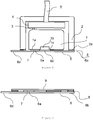
- Figure 1 shows a schematic representation of a gas-equilibrated, volatile-in-water detector, in which a gas sensor 1 is contained within a gas sensor cradle 2.
- the gas sensor is preferably of cylindrical shape, and typically of 20 mm diameter and 16.6 mm height, excluding contact pins 3, as provided as a received industrial standard by gas sensor manufacturers such as Alphasense Ltd, Dynament Ltd and City Technology Ltd.
- the gas sensor preferably is disposed to sit upon, and make electrical connection via 3 to, a small printed circuit board (PCB), 4, itself electrically connected to a cable 5, through which power is delivered to the gas sensor and signals are communicated to and from the sensor to some external means of control such as a computer, via, by way of example, a universal serial port.
- PCB printed circuit board
- the cradle 2 and PCB 4 are positioned so that the face, 1a, of the gas sensor containing a gas sensing orifice 1b, is approximately co-planar with the cradle wall flat surfaces 2a.
- Gas porous PTFE membrane 6, some 280 - 300 m -6 thick, is attached by means of a thin adhesive layer 7 to the sensor face 1a.
- a further portion 6b of the membrane is attached by means of a thin layer of adhesive 8 to the cradle wall flats 2a, thereby forming an entry point to a second gaseous enclosure external of the gas sensor 1.
- the adhesive on the membrane does not extend beyond its point of contact to the gas sensor face 1a at the periphery of the gas sensing orifice 1c.
- the membrane portion 6c is on the contrary, substantially free of adhesives which could prevent gas flow into or out of the gas orifice.
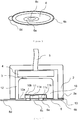
- Figure 2 shows the membrane assembly of Figure 1 prior to its deployment. Additional to the components already described, the membrane includes a waxed paper or other removable member 9 to protect adhesive portions of the membrane before use.
- Figure 3 shows the membrane assembly of Figure 2 from a different perspective, with the adhesive-protective element removed.
- FIG 4 shows a schematic representation of a gas-equilibrated, volatile-in-water probe provided by the invention wherein a gas sensor body 10 contains a removable and replaceable gas receiving and sensing member 11.
- a gas sensor body 10 contains a removable and replaceable gas receiving and sensing member 11.
- An example of such a sensor is the 16.6 mm x 20mm diameter miniature photoionisation detector (PID) manufactured by Ion Science Limited and containing an electrode pellet as described and claimed in our GB 2449664 B .
- PID miniature photoionisation detector
- PCB 4 is also in electrical contact with cable 5, as described in reference to corresponding components 3, 4 and 5 in Figure 1 .
- Gas sensing member 11 is approximately pellet shaped, and includes an orifice for receiving gas, 11a, on its outwardly facing major surface, 11b, opposing its other major surface proximal to the sensor body cavity (gas sensing chamber) 10b containing the gas sensing member 11.
- Surface 11b of the gas sensing member 11 is approximately co-planar with sensor body surface 10a, and also approximately co-planar with cradle wall flats 2a.
- Gas sensing member 11 is attached at annulus 11c to gas-porous or gas-permeable membrane 6 by means of an adhesive or ultrasonic welding of membrane portion 6a to the gas sensing member flat surface 11b close to the periphery of gas orifice 11a. It is preferable for the membrane portion 6a joined to gas sensing member portion 11c not to be porous or permeable to gas, either by virtue of an impermeable adhesive being applied to and impregnating the membrane, or by the membrane 6 and gas sensing member face 11b being welded at the point of fusion so as to form a seal that is neither porous nor appreciably permeable.
- the membrane 6 is also attached to cradle wall flats 2a by means of adhesive 13 at annulus 6b, thereby forming an entry point to a second gaseous enclosure 12 external of the gas-sensing chamber.
- the membrane is substantially porous or vapour-permeable over that portion overlaying gas orifice 11a and bounded by the impervious seal between annulus 6a and portion 11c.
- the membrane portion between annular seals 6a and 6b may or may not be porous or permeable according to the benefit conferred by enabling gaseous analyte gas irrigation at potential leak paths between probe members 10 and 11.
- the membrane 6 further may include a tab 6d for convenient removal of the membrane 6 after use.
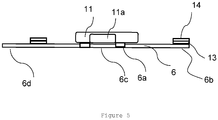
- Figure 5 shows a replaceable gas sensing sub-assembly comprising components 11 and 6 prior to their assembly in the probe shown schematically in figure 4 .
- This replaceable component includes a removable protective cover 14 to protect the adhesive portion of the membrane 6b.
- the sensor 1 In the case of a gas sensor containing an integral means of gas admittance, such as is described in Figure 1 , it is preferable for the sensor 1 to be removed from the cradle 2 over times of significant storage.
- the sensor is manually fitted in the cradle ensuring pins from the sensor 3 fit snugly into PCB platform 4.
- the covering 9 is removed from a disposable membrane assembly such as shown in Figure 2 , and placed over the cradle wall flats 2a and sensor face 1a to make a seal.
- the membrane and cradle to include means of co-alignment such as notches (not shown).
- the probe is now connected to a means of power supply and data communication via cable 5.
- the probe may be calibrated by placing a gas hood over the assembled probe, and presenting a suitable concentration of the analyte to the gas hood.
- the probe may be calibrated using an aqueous liquid, typically pure water, into which the gaseous analyte is dissolved.
- the former is generally preferable, and provides an advantage of using a gas-equilibrated, volatile-in-liquid detector over other volatile-in-water detection technologies. These previous detectors require aqueous reference samples, which are prone to loose the volatile as soon as their means of containment, typically a glass ampoule, is breached.
- the cable 5 connected to the probe is flexible and armoured or sheathed so as to provide protection when submerged in a watery fluid, perhaps under very adverse conditions.
- the probe may include additional members to ensure to protect the assembly from damage, particularly the probe itself. It is however deleterious for the membrane 6 to be appreciably obscured from the aqueous environment presented to it, insofar as free flow of fluids across it is needed for dynamic sensing.
- the removal of the sensor may benefit from additional cradle members, not shown in Figure 1 , which enable the cradle walls surrounding the circular or cylindrical section of the gas sensor to be partly dismantled.
- the sensor shown in Figure 4 is best stored with its removable components removed from the sensor cradle 2.
- the sensor may be manually assembled as described above, although in this case the membrane assembly shown in Figure 5 is affixed to the sensor cradle 2 only after careful orientation and assembly of gas sensor sub-components.
- a lamp is first inserted in the gas sensing member 11 opposite the membrane orifice 11a. Then the protective backing 14 to the adhesive section is removed. Then the membrane assembly is placed over the cradle wall flats 2a as shown in Figure 4 and pressed down to ensure a water tight seal.
- the probe shown in Figure 4 Following tests with the probe shown in Figure 4 , it is again advisable for the probe to be washed off in clean water and dried.
- the membrane 6 is peeled off cradle wall flats 2a.
- the entire sub-assembly shown in Figure 5 is removable and disposable, being a small, environmentally benign and modest cost item.
- the sensor body can then be removed and stored in a separate storage capsule or refitted with a new membrane assembly as depicted in Figure 5 , ready for subsequent use.
- the instrument is calibrated as described above.
- the use of a gas for calibration is a particular advantage where the PID is being used to trace a volatile to which PID responds, with reasonable assurance as to the presence of that volatile. For example, it might be calibrated with 1 ppm xylene in air, using Henry's Law to determine the equivalent xylene-in-water concentration.
- Possible applications of the invention include, for example, remediation of polluted water, monitoring of potable water, food and drink processing, and regulatory enforcement.
Description
- This invention relates to detection of gaseous and volatile analytes dissolved in water and other aqueous fluids using a detector within which such materials are sensed in the gaseous phase. Analytes of particular interest are volatile organic compounds (VOCs) particularly as found in water and aqueous solutions in concentrations varying from less than a part per billion (ppb, 10-9) to parts per thousand (ppt, 10-3) by mass.
- There is a need to detect and measure the presence of organic contaminants in natural and artificially contained sources of water and other aqueous fluids. VOCs include irritants, oestrogens, carcinogens and other chemicals harmful to humans, animals and plant life. Rigorous standards are laid down for potable water supplies which must be carefully monitored. Similarly, open water such as rivers, lakes and the oceans must be monitored for contamination or pollution to prevent damage to plants, animals or adjoining land.
- Volatile and gaseous compounds dissolved in water are also of interest as analytes due to other deleterious effects, for example in accelerating corrosion of metal pipes and vessels, or simply as indicators of water process quality within certain environments, for example wash water used in an industrial closed loop process or in the detection of alcohols due to fermentation in food stuffs and in brewing.
- It is frequently of interest to search for the presence of gaseous species within large expanses of water, and to trace their source and extent in near real time, as for example may arise from spillage of petrochemicals into sea water arising due to a natural event, an accident or clandestine activity. Such bodies of water are also subject to currents and drift. Current methods of analysis for trace quantities of VOCs and other dissolved gaseous species, such as chromatography or spectroscopy, are too slow and expensive to provide a dynamic map of volatile concentrations within water. Instead, it is preferable to submerge sensors for the target analytes within the body of water to provide a fast and quantitative measurement of their concentration. Such sensors may not provide the most accurate measure of target analytes, indeed, they may often be of most service in screening for unusual concentrations of a suite of different analytes in water samples, which are then selectively forwarded for more expensive and time consuming detailed analysis.
- A class of such detectors contain a membrane, typically hydrophobic, providing a barrier between the aqueous sensed environment and a detector enclosure, through which the analyte is able to diffuse.
- In one subclass of such detector, the detector enclosure contains an aqueous liquid. A well known example of this type of sensor is the Clarke electrode', in which dissolved oxygen in water diffuses from the test environment through a sensor membrane into an electrolyte, contained within a sensor cavity which includes the membrane as one containment wall member. The dissolved oxygen is consumed at an electrode proximal to the membrane. Patent
DE20300514 U1 , Achim Rappl, provides another example of this type of detector, again for detecting dissolved oxygen. - In another subclass of such detectors, the detector membrane, which is in contact with the aqueous fluid on one side, forms the wall of a gaseous enclosure on the other, through which the analyte is able to diffuse. Hereinafter for convenience we shall refer to this type of detector as a gas partitioned volatile detector.
-
US patent 5,979,219, S Sellmer-Wilsberg et al. describes such a detector in which the membrane admits volatiles, which are then entrained within a carrier gas to a nearby gas sensor which is able to respond to a volatile such as ethanol. The carrier gas is needful to ensure that analyte entering the detector can be removed within a reasonable time frame. The need for carrier gas does however constrain the application of the device to circumstances in which a carrier gas flow can be supported. The carrier gas also acts as an analyte diluent, whereupon the sensitivity of a device provided by this invention is limited and its accuracy circumscribed by the extent of gas flow through the membrane. -
US 5,979,219 describes another gas partitioned volatile detector in which the membrane admits volatiles such as ethanol into the sensing gaseous enclosure which is then sensed by a proximal semiconducting gas sensor. The invention relies on a pressure relief system being continuously open in order to 'exhaust' gases, not least target volatiles, into the atmosphere [Col 2 lines 11-32,Col 3,lines 26-35] rendering a carrier gas to flush the sensor enclosure unnecessary [Col 2 line 31]. A problem to be expected with a detector made according to US '219 is that the rate of analyte escape from the detector gaseous chamber will be very slow and highly variable, according to factors which enable more or less rapid escape of gases from the pressure relief outlet to atmosphere at some considerable distance. The design may be sufficiently compact to enable detector response and cleardown in the time frame of half a day, as may be useful in brewing, but not within a minute or two, as may be required, for example, in sensing volatiles in a sensor train behind a boat or in a water process stream. -
US 7,385,191 B1 , assigned to Pacific Environmental Technologies, LLC, provides another illustration of a gas partitioned volatile detector in which a much more rapid response time is assured by the continuous vacuum purge required for the mass spectrometer sensing gases permeating the gas-permeable membrane. It is however, liable to be limited by the burden of cost and care that is need to maintain a vacuum system, not to mention practicalities of its being used in all weathers by persons who may have limited training in the use of vacuum systems. - In the absence of an air purge or a gas release means or a vacuum system, a further means of analyte removal from a gas partitioned volatile detector may be provided by the gas sensor or gas sensing element itself consuming the analyte, as is illustrated in
EP0734516A1 , Commonwealth Scientific and Industrial Research Organisation, which describes an amperommetric oxygen sensor behind a diffusive membrane. - Analyte detection may be contemplated by way of infrared sensors such as disclosed in
US 8,383,046 or by humidity sensors such as disclosed inWO2006/042546 . Most prior art to date does not appear to include a gas partitioned volatile detector in which neither does the gas sensing element consume the analyte, nor does the detector use some means of gas evacuation to remove the analyte. One exception to this isUS 8,383,046 which utilises an IR detector typically having a volume of 400mm3. This technology is dependent on having a relatively large volume sample in order to register the presence of the analyte. The downside of this is that the time taken to fill the chamber (by equilibration of analyte across a sensor membrane) to an appreciable level for a reading to be taken makes for a sensor whose response time is unacceptably high. - The present invention recognises this and all previously described problems and attempts to mitigate them by way of a novel detector arrangement. Hereinafter for convenience we will refer to this type of detector as a gas-equilibrated, volatile-in-liquid detector.
- This detector provides a significant advantage over other gas-partitioned volatile detectors, in prospectively delivering a partial pressure of gas in the gaseous enclosure p in equilibrium with the concentration of gas in the liquid phase, c. When this condition is achieved, Henry's Law is obeyed. Specifically, p = k H x c, where k H is Henry's constant. Temperature dependent constants k H are known for a plethora of important volatiles and thus, prospectively, the response of a gas sensing element can be directly related to the concentration of the gas in the liquid phase. Thus, it requires only the gas sensing element in the gas-equilibrated, volatile-in-liquid detector to be reliable in sensing a target analyte for the concentration of a volatile in an adjoining liquid phase to be known. The detector can provide a measurement of a volatile in a liquid which does not vary directly with the rate of supply of analyte to the sensor, as determined either: by the rate of consumption or dispersion of analyte by components within the detector; or by the permeability or porosity of any intervening membrane.
- A possible reason why the prior art may not have been directed towards gas-equilibrated, volatile-in-liquid detectors is that in order to achieve gas/liquid equilibrium, particularly for volatile analytes for which k H is large and for which accordingly the volatile is only scarcely soluble in water, the volatile must be abstracted in substantial quantity from the sampled aqueous phase, and that that this volumetric demand for analyte on the sample side increases in proportion to the volume of the gaseous enclosure containing the gas sensing element. The gaseous enclosure within a gas-equilibrated, volatile-in-liquid detector is therefore required to be smaller than is demanded commonly of atmospheric gas sensing devices monitoring. Unlike other detectors engaging a water-gas partition, such as those of
US 5979219 ,US 7385191 B1 ,DE20300514 U1 andEP0734516A1 referred to above, the effectiveness of this type of detector requires the elimination of all means of removal of gas from the gaseous enclosure within the sensor except from the membrane itself. Achieving this condition is not trivial. - Another problem we have encountered in the discovery of the present invention is that gas sensors and gas sensing sub-assemblies suitable for the measurement of analyte in equilibrium with an adjoining liquid phase commonly include a gaseous enclosure characterised by its being contiguous, sometimes unavoidably, with tortuous and convoluted gaseous spaces between sub-assembled components and with capillary leak sites, all of which provide an appreciable sink for analyte when compared to the slow rate of supply and removal of analyte though the partition separating the gas enclosure from the liquid containing the analyte.
- A further difficulty arises from the need to obtain a sufficient flux through the membrane separating an aqueous environment from a gaseous enclosure to ensure reasonably fast equilibration of the analyte within the gaseous enclosure. To obtain this, it is commonly preferable to engage a porous hydrophobic membrane as a partition between the liquid and the detector's gaseous enclosure. Placement and sealing of the membrane is problematic. Placement and seal at some separation from the gas sensor or sensing sub-assembly within the detector requires an intervening membrane support, to ensure the membrane does not rupture under a pressure presented by the liquid abutting its external face, as taught for example by
US 5979219 . Remoteness of the membrane from the gas sensing element in an equilibrated detector adds significantly to the time required for equilibration of gas within an equilibrated detector. If the gaseous enclosure members are used to support and seal the membrane, without the use of an o-ring, and contrary to the normal practice in the art as to how such liquid/gas seals should be assured, then any membrane rupture or leakage will lead to ingress of liquid into the gaseous enclosure, prospectively proceeding to corrode electrically connected gaseous sensing components and causing the sensor to be worthless. - We have invented a photoionisation (PID) detector sensor head according to
claim 1 capable of detecting and measuring organic materials in water, particularly at trace concentrations, which can provide real time measurements in a field environment, with little additional procedure than is required in the use of a typical gas detectors, and which enables easily calculated determination of the concentration of such organic materials in water, when their identity is known. - According to the present invention, a photoionisation detector (PID) sensor head is provided for use in a detector of volatiles in aqueous media as set forth in
claim 1 of the appended claims. - Thus, we provide a detector of volatiles in water and aqueous fluids, which contains as one member a vapour-porous or vapour-permeable membrane forming a wall of a gaseous enclosure in which concentration of gas in the enclosure is substantively achieved by means of analyte flux through the membrane.
- The membrane may also be sealed to an external wall of the gas-sensing chamber or of a surrounding enclosure, which may form part of a separable gas sensing sub-assembly or easily removable sensor. This outer seal may be a peelable adhesive. Conveniently, the two seals are concentric.
- In this configuration, the vapour-porous or vapour-permeable membrane forms an entry point to a second gaseous enclosure external of the gas-sensing chamber. This can reduce the effect of leaks between sub-components of the sensor assembly, by enabling gas equilibration in the space between the gas sensor and walls containing it.
- It is preferable for the membrane sealing the gas sensing sub-assembly or gas sensor to extend beyond its point of sealing to the sensor to affect a further seal to outer detector components, such that, upon removal of the membrane, the gas sensor or sensor sub-assembly may be removed from the detector. To facilitate this, it is convenient for the gas sensor or gas sensing sub-assembly to receive gas from an orifice in a planar supporting surface, which is contrived to be in the plane of the termination of detector wall members to which the outer membrane seal is made.
- It is self-evident that, as far as possible, the membrane must exclude liquid water from the gas-sensing chamber. Conveniently, the membrane is hydrophobic. A suitable material may be porous polytetrafluoroethylene (PTFE) or polyvinylidene difluoride (PVDF), either stand alone or as a coating on a porous substrate such as polypropylene. Typically, the overall thickness is some 100 - 500 m-6 and the pore size is approximately 0.5 m-6.
- The seal to the outer membrane member may be effected by means of an adhesive layer on a hydrophobic surface such as PTFE.
- The membrane may contain an annulus of adhesive to effect sealing of the gas sensor or gas sensing subcomponent.
- Ideally, the seal to the periphery of the chamber orifice is a vapour-impermeable barrier throughout the thickness of the membrane. This is normally a weld, particularly ultrasonic, between the membrane material and the gas sensor or gas sensing sub-assembly but can also be an impermeable adhesive penetrating the membrane.
- The invention in a further aspect provides for membrane material between the outer membrane to detector wall seal and the inner gas membrane to gaseous sensor seal or membrane to gaseous sensing sub-assembly seal to be vapour-permeable or vapour-porous.
- It is preferable for all porous surfaces to comprise porous PTFE.
- Without limitation, it is believed that the vapour detector measures the partial pressure of the organic materials in the vapour phase. Particularly at low concentrations, this measurement is a function of the concentration of the organic material in the liquid water.
- Advantageously, the gas-sensing chamber is so configured as to minimise dead volume therein. Conveniently, according to the invention the internal volume of the gas-sensing chamber is no greater than 100 mm3.
- Advantageously, the electrodes or other sensing system components within a sensor or sensing sub-assembly according to the present invention are stacked, with only a modest spacing between the sensing components such that the entire thickness of the sensing enclosure is no greater than a few millimetres. Thereby, the water from which organic volatiles pass through the membrane is in very close proximity to the entirety of the gas sensing enclosure, typically within 2 mm. The sensor may include a plurality of electrode contacts which, in an assembled position, lie in a common plane in the gas-sensing chamber and as close as possible to the overlying membrane.
- A particularly beneficial stacking arrangement for the electrodes is described and claimed in our patent
GB 2449664 B, filed 30 June 2007 US 7821270 B2 issued 26 October 2010 and others elsewhere). The electrode stack of this patent is well-suited to use with a miniature photoionisation detector. -
-
Figure 1 shows a schematic representation of a gas-equilibrated, volatile-in-water detector not within the scope of the invention. -
Figure 2 is an elevation of the membrane assembly ofFigure 1 prior to its deployment. -
Figure 3 shows the membrane assembly ofFigure 2 from a different perspective. -
Figure 4 shows a schematic representation of a gas-equilibrated, volatile-in-water probe according to the invention wherein a gas sensor body contains a removable and replaceable gas receiving and sensing member. -
Figure 5 shows a gas sensing replaceable sub-assembly prior to assembly in the probe shown schematically inFigure 4 . - The invention will now be described in more detail by reference to the drawings provided.
-
Figure 1 shows a schematic representation of a gas-equilibrated, volatile-in-water detector, in which agas sensor 1 is contained within agas sensor cradle 2. The gas sensor is preferably of cylindrical shape, and typically of 20 mm diameter and 16.6 mm height, excluding contact pins 3, as provided as a received industrial standard by gas sensor manufacturers such as Alphasense Ltd, Dynament Ltd and City Technology Ltd. The gas sensor preferably is disposed to sit upon, and make electrical connection via 3 to, a small printed circuit board (PCB), 4, itself electrically connected to acable 5, through which power is delivered to the gas sensor and signals are communicated to and from the sensor to some external means of control such as a computer, via, by way of example, a universal serial port. Thecradle 2 andPCB 4 are positioned so that the face, 1a, of the gas sensor containing agas sensing orifice 1b, is approximately co-planar with the cradle wallflat surfaces 2a. Gasporous PTFE membrane 6, some 280 - 300 m-6 thick, is attached by means of a thinadhesive layer 7 to thesensor face 1a. Afurther portion 6b of the membrane is attached by means of a thin layer of adhesive 8 to thecradle wall flats 2a, thereby forming an entry point to a second gaseous enclosure external of thegas sensor 1. The adhesive on the membrane does not extend beyond its point of contact to thegas sensor face 1a at the periphery of the gas sensing orifice 1c. Over at least its area of coverage of the gas orifice, themembrane portion 6c is on the contrary, substantially free of adhesives which could prevent gas flow into or out of the gas orifice. There may be anadditional membrane component 6d, which extends beyondcradle wall segments 2a, enabling the membrane to be peeled off after field use, rather than being stored, possibly wet and contaminated, attached to other detector members. -
Figure 2 shows the membrane assembly ofFigure 1 prior to its deployment. Additional to the components already described, the membrane includes a waxed paper or otherremovable member 9 to protect adhesive portions of the membrane before use.Figure 3 shows the membrane assembly ofFigure 2 from a different perspective, with the adhesive-protective element removed. -
Figure 4 shows a schematic representation of a gas-equilibrated, volatile-in-water probe provided by the invention wherein agas sensor body 10 contains a removable and replaceable gas receiving and sensingmember 11. An example of such a sensor is the 16.6 mm x 20mm diameter miniature photoionisation detector (PID) manufactured by Ion Science Limited and containing an electrode pellet as described and claimed in ourGB 2449664 B -
Sensor body 10 is seated onPCB 4, with which it makes electrical contact by means ofpins 3.PCB 4 is also in electrical contact withcable 5, as described in reference to correspondingcomponents Figure 1 . -
Gas sensing member 11 is approximately pellet shaped, and includes an orifice for receiving gas, 11a, on its outwardly facing major surface, 11b, opposing its other major surface proximal to the sensor body cavity (gas sensing chamber) 10b containing thegas sensing member 11.Surface 11b of thegas sensing member 11 is approximately co-planar withsensor body surface 10a, and also approximately co-planar withcradle wall flats 2a. -
Gas sensing member 11 is attached atannulus 11c to gas-porous or gas-permeable membrane 6 by means of an adhesive or ultrasonic welding ofmembrane portion 6a to the gas sensing memberflat surface 11b close to the periphery ofgas orifice 11a. It is preferable for themembrane portion 6a joined to gassensing member portion 11c not to be porous or permeable to gas, either by virtue of an impermeable adhesive being applied to and impregnating the membrane, or by themembrane 6 and gassensing member face 11b being welded at the point of fusion so as to form a seal that is neither porous nor appreciably permeable. - The
membrane 6 is also attached to cradlewall flats 2a by means of adhesive 13 atannulus 6b, thereby forming an entry point to a secondgaseous enclosure 12 external of the gas-sensing chamber. The membrane is substantially porous or vapour-permeable over that portion overlayinggas orifice 11a and bounded by the impervious seal betweenannulus 6a andportion 11c. The membrane portion betweenannular seals probe members membrane 6 further may include atab 6d for convenient removal of themembrane 6 after use. -
Figure 5 shows a replaceable gas sensingsub-assembly comprising components figure 4 . This replaceable component includes a removableprotective cover 14 to protect the adhesive portion of themembrane 6b. - The use of the sensors will now be described by reference to how they are operated in order to measure volatiles present in a watery liquid.
- In the case of a gas sensor containing an integral means of gas admittance, such as is described in
Figure 1 , it is preferable for thesensor 1 to be removed from thecradle 2 over times of significant storage. The sensor is manually fitted in the cradle ensuring pins from thesensor 3 fit snugly intoPCB platform 4. Thecovering 9 is removed from a disposable membrane assembly such as shown inFigure 2 , and placed over thecradle wall flats 2a andsensor face 1a to make a seal. To ensure correct alignment of the membrane to the sensor face, such that a porous and permeable part of themembrane 6c overlays thegas sensing orifice 1b it is preferable for the membrane and cradle to include means of co-alignment such as notches (not shown). - The probe is now connected to a means of power supply and data communication via
cable 5. The probe may be calibrated by placing a gas hood over the assembled probe, and presenting a suitable concentration of the analyte to the gas hood. Alternatively, the probe may be calibrated using an aqueous liquid, typically pure water, into which the gaseous analyte is dissolved. The former is generally preferable, and provides an advantage of using a gas-equilibrated, volatile-in-liquid detector over other volatile-in-water detection technologies. These previous detectors require aqueous reference samples, which are prone to loose the volatile as soon as their means of containment, typically a glass ampoule, is breached. - Typically the
cable 5 connected to the probe is flexible and armoured or sheathed so as to provide protection when submerged in a watery fluid, perhaps under very adverse conditions. The probe may include additional members to ensure to protect the assembly from damage, particularly the probe itself. It is however deleterious for themembrane 6 to be appreciably obscured from the aqueous environment presented to it, insofar as free flow of fluids across it is needed for dynamic sensing. - The removal of the sensor may benefit from additional cradle members, not shown in
Figure 1 , which enable the cradle walls surrounding the circular or cylindrical section of the gas sensor to be partly dismantled. - The sensor shown in
Figure 4 is best stored with its removable components removed from thesensor cradle 2. The sensor may be manually assembled as described above, although in this case the membrane assembly shown inFigure 5 is affixed to thesensor cradle 2 only after careful orientation and assembly of gas sensor sub-components. In the PID sensor, a lamp is first inserted in thegas sensing member 11 opposite themembrane orifice 11a. Then theprotective backing 14 to the adhesive section is removed. Then the membrane assembly is placed over thecradle wall flats 2a as shown inFigure 4 and pressed down to ensure a water tight seal. - Following tests with the probe shown in
Figure 4 , it is again advisable for the probe to be washed off in clean water and dried. Themembrane 6 is peeled offcradle wall flats 2a. After removal of the sensor, the entire sub-assembly shown inFigure 5 is removable and disposable, being a small, environmentally benign and modest cost item. The sensor body can then be removed and stored in a separate storage capsule or refitted with a new membrane assembly as depicted inFigure 5 , ready for subsequent use. - The instrument is calibrated as described above. In the PID, the use of a gas for calibration is a particular advantage where the PID is being used to trace a volatile to which PID responds, with reasonable assurance as to the presence of that volatile. For example, it might be calibrated with 1 ppm xylene in air, using Henry's Law to determine the equivalent xylene-in-water concentration.
- Possible applications of the invention include, for example, remediation of polluted water, monitoring of potable water, food and drink processing, and regulatory enforcement.
Claims (15)
- A photoionisation detector (PID) sensor head for use in a detector of volatiles in aqueous media, which head includes a miniature photoionisation detector comprising a gas sensor body (10) and a replaceable gas sensing member (11), said gas sensor body (10) having a sensor body cavity defining a gas sensing chamber (10b) containing said gas sensing member (11), the head further including a vapour-porous or vapour-permeable membrane (6) forming an entry point (6c) into the otherwise closed gas-sensing chamber, characterised in that the internal volume of the gas-sensing chamber (10b) is no greater than 100 mm3.
- A sensor head as claimed in claim 1, wherein the membrane (6) is sealed to the periphery of a chamber orifice (11a) by means of a chamber orifice seal (7) and forms an entry point to a second gaseous enclosure external to the gas-sensing chamber.
- A sensor head as claimed in claim 1 or 2, wherein a surrounding enclosure seal (8) seals the membrane (6) to an external wall (2a) of the gas-sensing chamber or of a surrounding enclosure.
- A sensor head as claimed in claim 13, wherein the external wall seal (8) seals by means of a peelable adhesive.
- A sensor head as claimed in claim 13 or 14, wherein the two seals (7,8) are concentric.
- A sensor head as claimed in any preceding claim depending from claim 2, wherein the gas-sensing chamber orifice (11a) is in a planar supporting surface coplanar with the termination of a wall of a surrounding enclosure (2).
- A sensor head as claimed in any preceding claim depending from claim 2, wherein the seal (7) to the periphery of the chamber orifice (11a) is a vapour-impermeable barrier throughout the thickness of the membrane (6).
- A sensor head as claimed in any preceding claim depending from claim 2, wherein the or each seal (7,8) is an annulus.
- A sensor head as claimed in claims 1 to 8, wherein the membrane (6) is hydrophobic.
- A sensor head as claimed in claims 1 to 9, which is detachable from an assembly supporting the sensor head.
- A sensor head as claimed in any claim depending from claim 2, wherein the seal (7) to the periphery of the chamber orifice is a weld or an impermeable adhesive penetrating the membrane (6).
- A sensor head as claimed in claims 1 to 11, wherein the sensor (10, 11) included in the sensor head includes a plurality of electrode contacts which lie in a common plane in the gas-sensing chamber.
- A sensor head as claimed in claims 11 to 12, wherein the gas-sensing chamber (10b) is so configured as to minimise dead volume therein.
- A sensor head as claimed in claims 1 to 13, wherein elements of the sensor are within 2mm of the membrane (6)so as to reduce the response time of the sensor.
- A gas-equilibrated, volatile-in-liquid detector incorporating a sensor head as claimed in any one of Claims 1 to 14.
Applications Claiming Priority (2)
| Application Number | Priority Date | Filing Date | Title |
|---|---|---|---|
| GB1421306.0A GB2527867B (en) | 2014-12-01 | 2014-12-01 | Detection of organics in water |
| PCT/IB2015/059177 WO2016088008A1 (en) | 2014-12-01 | 2015-11-27 | Photoionization detector system for organics in water |
Publications (3)
| Publication Number | Publication Date |
|---|---|
| EP3227676A1 EP3227676A1 (en) | 2017-10-11 |
| EP3227676B1 true EP3227676B1 (en) | 2018-10-31 |
| EP3227676B8 EP3227676B8 (en) | 2019-02-27 |
Family
ID=52349738
Family Applications (1)
| Application Number | Title | Priority Date | Filing Date |
|---|---|---|---|
| EP15812886.8A Active EP3227676B8 (en) | 2014-12-01 | 2015-11-27 | Photoionization detector system for organics in water |
Country Status (6)
| Country | Link |
|---|---|
| US (1) | US20170269049A1 (en) |
| EP (1) | EP3227676B8 (en) |
| JP (1) | JP6359773B2 (en) |
| CN (1) | CN107209162B (en) |
| GB (1) | GB2527867B (en) |
| WO (1) | WO2016088008A1 (en) |
Families Citing this family (3)
| Publication number | Priority date | Publication date | Assignee | Title |
|---|---|---|---|---|
| GB2537361B (en) | 2015-04-10 | 2017-05-03 | Ion Science Ltd | A Water Immersible Detector |
| GB2537881A (en) * | 2015-04-29 | 2016-11-02 | Ion Science Ltd | A method of operating a photoionisation detector to detect VOC's dissolved in water |
| US11604164B2 (en) * | 2020-12-14 | 2023-03-14 | Molex, Llc | Photoionization detector and method of operating same |
Family Cites Families (14)
| Publication number | Priority date | Publication date | Assignee | Title |
|---|---|---|---|---|
| US4745796A (en) * | 1987-03-16 | 1988-05-24 | Honeywell Inc. | Membrane-selective vapor sensing |
| US4892383A (en) * | 1989-02-17 | 1990-01-09 | Fiberchem Inc. | Reservoir fiber optic chemical sensors |
| JP2810804B2 (en) * | 1991-03-30 | 1998-10-15 | 日本電子株式会社 | Electron capture detector |
| AUPM707494A0 (en) * | 1994-07-26 | 1994-08-18 | Crc For Waste Management And Pollution Control Limited | A method and apparatus for environmental monitoring of low concentration levels of organic compounds |
| US5979219A (en) * | 1997-02-03 | 1999-11-09 | Sylvia Sellmer Wilsberg | Probe for measuring volatile components in an aqueous solution |
| US6272938B1 (en) * | 2000-04-07 | 2001-08-14 | General Electric Company | Monitoring of volatile organic compounds in groundwater with an in-situ sampling device |
| DE202004000570U1 (en) * | 2004-01-09 | 2004-03-18 | Ufz-Umweltforschungszentrum Leipzig-Halle Gmbh | Off-site/on-line/in-situ process to measure the presence of organic substances in fluids or vapors with a photo-ionization detector located within a watertight housing |
| US8383046B1 (en) * | 2007-04-16 | 2013-02-26 | Murthy Tata | Analyzer apparatus for measuring dissolved volatile substances and method |
| GB2449664B (en) * | 2007-05-30 | 2011-12-14 | Ion Science Ltd | Electrode contact pellet and associated photoionisation detector assembly |
| US7930924B2 (en) * | 2007-09-28 | 2011-04-26 | Vancouver Island University | System for the online measurement of volatile and semi-volatile compounds and use thereof |
| JP5272466B2 (en) * | 2008-03-21 | 2013-08-28 | 株式会社Ihi | Sensor system for measuring dissolved gas concentration for underwater robots |
| EP2606331B1 (en) * | 2010-08-19 | 2020-05-06 | Inficon AB | Gas sensor housing |
| KR20140143403A (en) * | 2012-03-13 | 2014-12-16 | 엠케이에스 인스트루먼츠, 인코포레이티드 | Trace gas concentration in art ms traps |
| CN104181284B (en) * | 2014-07-11 | 2016-03-09 | 上海市政工程设计研究总院(集团)有限公司 | A kind of Volatile Organic Compounds in Soil continuous detection apparatus and detection method thereof |
-
2014
- 2014-12-01 GB GB1421306.0A patent/GB2527867B/en active Active
-
2015
- 2015-11-27 JP JP2017530201A patent/JP6359773B2/en not_active Expired - Fee Related
- 2015-11-27 EP EP15812886.8A patent/EP3227676B8/en active Active
- 2015-11-27 WO PCT/IB2015/059177 patent/WO2016088008A1/en active Application Filing
- 2015-11-27 US US15/532,070 patent/US20170269049A1/en not_active Abandoned
- 2015-11-27 CN CN201580075172.8A patent/CN107209162B/en not_active Expired - Fee Related
Non-Patent Citations (1)
| Title |
|---|
| None * |
Also Published As
| Publication number | Publication date |
|---|---|
| GB2527867B (en) | 2016-06-29 |
| EP3227676B8 (en) | 2019-02-27 |
| CN107209162B (en) | 2019-12-13 |
| GB2527867A (en) | 2016-01-06 |
| JP6359773B2 (en) | 2018-07-18 |
| WO2016088008A1 (en) | 2016-06-09 |
| GB201421306D0 (en) | 2015-01-14 |
| US20170269049A1 (en) | 2017-09-21 |
| JP2017537323A (en) | 2017-12-14 |
| EP3227676A1 (en) | 2017-10-11 |
| CN107209162A (en) | 2017-09-26 |
Similar Documents
| Publication | Publication Date | Title |
|---|---|---|
| Ohira et al. | A fiber optic sensor with a metal organic framework as a sensing material for trace levels of water in industrial gases | |
| US9884269B2 (en) | Methods and systems for selective hydrogen gas extraction for dissolved gas analysis applications | |
| US20100005881A1 (en) | Protective device for a humidity sensor in an aggressive atmosphere | |
| EP3227676B1 (en) | Photoionization detector system for organics in water | |
| US8537020B2 (en) | Visual indicator of gas sensor impairment | |
| US8916037B1 (en) | Instrument and method for measuring high concentrations of carbon monoxide in a gaseous sample | |
| JP2017133999A (en) | Water quality analysis device and water quality analysis method | |
| CA2345801C (en) | Instrument for combustible gas detection | |
| US8383046B1 (en) | Analyzer apparatus for measuring dissolved volatile substances and method | |
| GB2335277A (en) | Mounting sensor carrying wafer in water quality measuring apparatus | |
| Martinotti et al. | A flow injection analyser conductometric coupled system for the field analysis of free dissolved CO 2 and total dissolved inorganic carbon in natural waters | |
| Shitashima et al. | Development of in situ pH sensor using ISFET | |
| Cowie et al. | Membrane inlet ion trap mass spectrometry for the direct measurement of dissolved gases in ecological samples | |
| EP3281002B1 (en) | A water immersible detector | |
| US20190242841A1 (en) | Hydrophobic and oleophobic cover for gas sensing module | |
| CN108139348B (en) | Refrigerant analyzer and method of use | |
| RU2568331C1 (en) | Device determining leaks of explosive liquids based on piezoelectric sensor | |
| US20060120920A1 (en) | Hydrogen or helium sensor | |
| CA2265304A1 (en) | A method and instrument for detection and measurement of low levels of gases with applications in chemical defense and environmental monitoring | |
| JP2004163370A (en) | Adapter for measuring high concentration gas | |
| US20230358703A1 (en) | Electrochemical sensor including a measuring cell and an oxidation component and process using such a sensor | |
| ITRM980584A1 (en) | DEVICE FOR DIFFUSIONAL SAMPLING OF ORGANIC VAPORS IN THE ENVIRONMENT | |
| CZ24156U1 (en) | Permeation cell for monitoring permeation of toxic substances with barrier materials | |
| Korotcenkov et al. | Chemical sensors selection and operation guide | |
| GB2537881A (en) | A method of operating a photoionisation detector to detect VOC's dissolved in water |
Legal Events
| Date | Code | Title | Description |
|---|---|---|---|
| STAA | Information on the status of an ep patent application or granted ep patent |
Free format text: STATUS: THE INTERNATIONAL PUBLICATION HAS BEEN MADE |
|
| PUAI | Public reference made under article 153(3) epc to a published international application that has entered the european phase |
Free format text: ORIGINAL CODE: 0009012 |
|
| STAA | Information on the status of an ep patent application or granted ep patent |
Free format text: STATUS: REQUEST FOR EXAMINATION WAS MADE |
|
| 17P | Request for examination filed |
Effective date: 20170703 |
|
| AK | Designated contracting states |
Kind code of ref document: A1 Designated state(s): AL AT BE BG CH CY CZ DE DK EE ES FI FR GB GR HR HU IE IS IT LI LT LU LV MC MK MT NL NO PL PT RO RS SE SI SK SM TR |
|
| AX | Request for extension of the european patent |
Extension state: BA ME |
|
| DAV | Request for validation of the european patent (deleted) | ||
| DAX | Request for extension of the european patent (deleted) | ||
| GRAP | Despatch of communication of intention to grant a patent |
Free format text: ORIGINAL CODE: EPIDOSNIGR1 |
|
| STAA | Information on the status of an ep patent application or granted ep patent |
Free format text: STATUS: GRANT OF PATENT IS INTENDED |
|
| INTG | Intention to grant announced |
Effective date: 20180522 |
|
| GRAS | Grant fee paid |
Free format text: ORIGINAL CODE: EPIDOSNIGR3 |
|
| GRAA | (expected) grant |
Free format text: ORIGINAL CODE: 0009210 |
|
| STAA | Information on the status of an ep patent application or granted ep patent |
Free format text: STATUS: THE PATENT HAS BEEN GRANTED |
|
| AK | Designated contracting states |
Kind code of ref document: B1 Designated state(s): AL AT BE BG CH CY CZ DE DK EE ES FI FR GB GR HR HU IE IS IT LI LT LU LV MC MK MT NL NO PL PT RO RS SE SI SK SM TR |
|
| REG | Reference to a national code |
Ref country code: CH Ref legal event code: EP Ref country code: GB Ref legal event code: FG4D |
|
| REG | Reference to a national code |
Ref country code: AT Ref legal event code: REF Ref document number: 1060005 Country of ref document: AT Kind code of ref document: T Effective date: 20181115 |
|
| REG | Reference to a national code |
Ref country code: DE Ref legal event code: R096 Ref document number: 602015019269 Country of ref document: DE |
|
| REG | Reference to a national code |
Ref country code: IE Ref legal event code: FG4D |
|
| RAP2 | Party data changed (patent owner data changed or rights of a patent transferred) |
Owner name: ION SCIENCE LIMITED |
|
| REG | Reference to a national code |
Ref country code: CH Ref legal event code: PK Free format text: BERICHTIGUNG B8 |
|
| REG | Reference to a national code |
Ref country code: LT Ref legal event code: MG4D |
|
| REG | Reference to a national code |
Ref country code: NL Ref legal event code: FP |
|
| REG | Reference to a national code |
Ref country code: AT Ref legal event code: MK05 Ref document number: 1060005 Country of ref document: AT Kind code of ref document: T Effective date: 20181031 |
|
| PG25 | Lapsed in a contracting state [announced via postgrant information from national office to epo] |
Ref country code: FI Free format text: LAPSE BECAUSE OF FAILURE TO SUBMIT A TRANSLATION OF THE DESCRIPTION OR TO PAY THE FEE WITHIN THE PRESCRIBED TIME-LIMIT Effective date: 20181031 Ref country code: NO Free format text: LAPSE BECAUSE OF FAILURE TO SUBMIT A TRANSLATION OF THE DESCRIPTION OR TO PAY THE FEE WITHIN THE PRESCRIBED TIME-LIMIT Effective date: 20190131 Ref country code: IS Free format text: LAPSE BECAUSE OF FAILURE TO SUBMIT A TRANSLATION OF THE DESCRIPTION OR TO PAY THE FEE WITHIN THE PRESCRIBED TIME-LIMIT Effective date: 20190228 Ref country code: AT Free format text: LAPSE BECAUSE OF FAILURE TO SUBMIT A TRANSLATION OF THE DESCRIPTION OR TO PAY THE FEE WITHIN THE PRESCRIBED TIME-LIMIT Effective date: 20181031 Ref country code: LV Free format text: LAPSE BECAUSE OF FAILURE TO SUBMIT A TRANSLATION OF THE DESCRIPTION OR TO PAY THE FEE WITHIN THE PRESCRIBED TIME-LIMIT Effective date: 20181031 Ref country code: LT Free format text: LAPSE BECAUSE OF FAILURE TO SUBMIT A TRANSLATION OF THE DESCRIPTION OR TO PAY THE FEE WITHIN THE PRESCRIBED TIME-LIMIT Effective date: 20181031 Ref country code: ES Free format text: LAPSE BECAUSE OF FAILURE TO SUBMIT A TRANSLATION OF THE DESCRIPTION OR TO PAY THE FEE WITHIN THE PRESCRIBED TIME-LIMIT Effective date: 20181031 Ref country code: BG Free format text: LAPSE BECAUSE OF FAILURE TO SUBMIT A TRANSLATION OF THE DESCRIPTION OR TO PAY THE FEE WITHIN THE PRESCRIBED TIME-LIMIT Effective date: 20190131 Ref country code: PL Free format text: LAPSE BECAUSE OF FAILURE TO SUBMIT A TRANSLATION OF THE DESCRIPTION OR TO PAY THE FEE WITHIN THE PRESCRIBED TIME-LIMIT Effective date: 20181031 Ref country code: HR Free format text: LAPSE BECAUSE OF FAILURE TO SUBMIT A TRANSLATION OF THE DESCRIPTION OR TO PAY THE FEE WITHIN THE PRESCRIBED TIME-LIMIT Effective date: 20181031 |
|
| PG25 | Lapsed in a contracting state [announced via postgrant information from national office to epo] |
Ref country code: AL Free format text: LAPSE BECAUSE OF FAILURE TO SUBMIT A TRANSLATION OF THE DESCRIPTION OR TO PAY THE FEE WITHIN THE PRESCRIBED TIME-LIMIT Effective date: 20181031 Ref country code: GR Free format text: LAPSE BECAUSE OF FAILURE TO SUBMIT A TRANSLATION OF THE DESCRIPTION OR TO PAY THE FEE WITHIN THE PRESCRIBED TIME-LIMIT Effective date: 20190201 Ref country code: SE Free format text: LAPSE BECAUSE OF FAILURE TO SUBMIT A TRANSLATION OF THE DESCRIPTION OR TO PAY THE FEE WITHIN THE PRESCRIBED TIME-LIMIT Effective date: 20181031 Ref country code: RS Free format text: LAPSE BECAUSE OF FAILURE TO SUBMIT A TRANSLATION OF THE DESCRIPTION OR TO PAY THE FEE WITHIN THE PRESCRIBED TIME-LIMIT Effective date: 20181031 Ref country code: PT Free format text: LAPSE BECAUSE OF FAILURE TO SUBMIT A TRANSLATION OF THE DESCRIPTION OR TO PAY THE FEE WITHIN THE PRESCRIBED TIME-LIMIT Effective date: 20190301 |
|
| REG | Reference to a national code |
Ref country code: CH Ref legal event code: PL |
|
| PG25 | Lapsed in a contracting state [announced via postgrant information from national office to epo] |
Ref country code: CZ Free format text: LAPSE BECAUSE OF FAILURE TO SUBMIT A TRANSLATION OF THE DESCRIPTION OR TO PAY THE FEE WITHIN THE PRESCRIBED TIME-LIMIT Effective date: 20181031 Ref country code: DK Free format text: LAPSE BECAUSE OF FAILURE TO SUBMIT A TRANSLATION OF THE DESCRIPTION OR TO PAY THE FEE WITHIN THE PRESCRIBED TIME-LIMIT Effective date: 20181031 |
|
| REG | Reference to a national code |
Ref country code: DE Ref legal event code: R097 Ref document number: 602015019269 Country of ref document: DE |
|
| REG | Reference to a national code |
Ref country code: IE Ref legal event code: MM4A |
|
| PG25 | Lapsed in a contracting state [announced via postgrant information from national office to epo] |
Ref country code: EE Free format text: LAPSE BECAUSE OF FAILURE TO SUBMIT A TRANSLATION OF THE DESCRIPTION OR TO PAY THE FEE WITHIN THE PRESCRIBED TIME-LIMIT Effective date: 20181031 Ref country code: SM Free format text: LAPSE BECAUSE OF FAILURE TO SUBMIT A TRANSLATION OF THE DESCRIPTION OR TO PAY THE FEE WITHIN THE PRESCRIBED TIME-LIMIT Effective date: 20181031 Ref country code: LI Free format text: LAPSE BECAUSE OF NON-PAYMENT OF DUE FEES Effective date: 20181130 Ref country code: RO Free format text: LAPSE BECAUSE OF FAILURE TO SUBMIT A TRANSLATION OF THE DESCRIPTION OR TO PAY THE FEE WITHIN THE PRESCRIBED TIME-LIMIT Effective date: 20181031 Ref country code: CH Free format text: LAPSE BECAUSE OF NON-PAYMENT OF DUE FEES Effective date: 20181130 Ref country code: SK Free format text: LAPSE BECAUSE OF FAILURE TO SUBMIT A TRANSLATION OF THE DESCRIPTION OR TO PAY THE FEE WITHIN THE PRESCRIBED TIME-LIMIT Effective date: 20181031 Ref country code: MC Free format text: LAPSE BECAUSE OF FAILURE TO SUBMIT A TRANSLATION OF THE DESCRIPTION OR TO PAY THE FEE WITHIN THE PRESCRIBED TIME-LIMIT Effective date: 20181031 |
|
| PLBE | No opposition filed within time limit |
Free format text: ORIGINAL CODE: 0009261 |
|
| STAA | Information on the status of an ep patent application or granted ep patent |
Free format text: STATUS: NO OPPOSITION FILED WITHIN TIME LIMIT |
|
| 26N | No opposition filed |
Effective date: 20190801 |
|
| PG25 | Lapsed in a contracting state [announced via postgrant information from national office to epo] |
Ref country code: IE Free format text: LAPSE BECAUSE OF NON-PAYMENT OF DUE FEES Effective date: 20181127 Ref country code: SI Free format text: LAPSE BECAUSE OF FAILURE TO SUBMIT A TRANSLATION OF THE DESCRIPTION OR TO PAY THE FEE WITHIN THE PRESCRIBED TIME-LIMIT Effective date: 20181031 |
|
| PGFP | Annual fee paid to national office [announced via postgrant information from national office to epo] |
Ref country code: LU Payment date: 20191120 Year of fee payment: 5 |
|
| PG25 | Lapsed in a contracting state [announced via postgrant information from national office to epo] |
Ref country code: MT Free format text: LAPSE BECAUSE OF NON-PAYMENT OF DUE FEES Effective date: 20181127 |
|
| PGFP | Annual fee paid to national office [announced via postgrant information from national office to epo] |
Ref country code: DE Payment date: 20191121 Year of fee payment: 5 Ref country code: NL Payment date: 20191120 Year of fee payment: 5 |
|
| PGFP | Annual fee paid to national office [announced via postgrant information from national office to epo] |
Ref country code: FR Payment date: 20191120 Year of fee payment: 5 Ref country code: BE Payment date: 20191120 Year of fee payment: 5 Ref country code: IT Payment date: 20191128 Year of fee payment: 5 |
|
| PG25 | Lapsed in a contracting state [announced via postgrant information from national office to epo] |
Ref country code: TR Free format text: LAPSE BECAUSE OF FAILURE TO SUBMIT A TRANSLATION OF THE DESCRIPTION OR TO PAY THE FEE WITHIN THE PRESCRIBED TIME-LIMIT Effective date: 20181031 |
|
| PG25 | Lapsed in a contracting state [announced via postgrant information from national office to epo] |
Ref country code: MK Free format text: LAPSE BECAUSE OF NON-PAYMENT OF DUE FEES Effective date: 20181031 Ref country code: HU Free format text: LAPSE BECAUSE OF FAILURE TO SUBMIT A TRANSLATION OF THE DESCRIPTION OR TO PAY THE FEE WITHIN THE PRESCRIBED TIME-LIMIT; INVALID AB INITIO Effective date: 20151127 Ref country code: CY Free format text: LAPSE BECAUSE OF FAILURE TO SUBMIT A TRANSLATION OF THE DESCRIPTION OR TO PAY THE FEE WITHIN THE PRESCRIBED TIME-LIMIT Effective date: 20181031 |
|
| REG | Reference to a national code |
Ref country code: DE Ref legal event code: R119 Ref document number: 602015019269 Country of ref document: DE |
|
| REG | Reference to a national code |
Ref country code: NL Ref legal event code: MM Effective date: 20201201 |
|
| PG25 | Lapsed in a contracting state [announced via postgrant information from national office to epo] |
Ref country code: LU Free format text: LAPSE BECAUSE OF NON-PAYMENT OF DUE FEES Effective date: 20201127 |
|
| REG | Reference to a national code |
Ref country code: BE Ref legal event code: MM Effective date: 20201130 |
|
| PG25 | Lapsed in a contracting state [announced via postgrant information from national office to epo] |
Ref country code: NL Free format text: LAPSE BECAUSE OF NON-PAYMENT OF DUE FEES Effective date: 20201201 |
|
| PG25 | Lapsed in a contracting state [announced via postgrant information from national office to epo] |
Ref country code: IT Free format text: LAPSE BECAUSE OF NON-PAYMENT OF DUE FEES Effective date: 20201127 Ref country code: FR Free format text: LAPSE BECAUSE OF NON-PAYMENT OF DUE FEES Effective date: 20201130 |
|
| PG25 | Lapsed in a contracting state [announced via postgrant information from national office to epo] |
Ref country code: DE Free format text: LAPSE BECAUSE OF NON-PAYMENT OF DUE FEES Effective date: 20210601 |
|
| PG25 | Lapsed in a contracting state [announced via postgrant information from national office to epo] |
Ref country code: BE Free format text: LAPSE BECAUSE OF NON-PAYMENT OF DUE FEES Effective date: 20201130 |
|
| PGFP | Annual fee paid to national office [announced via postgrant information from national office to epo] |
Ref country code: GB Payment date: 20231123 Year of fee payment: 9 |