EP3227635B1 - Verfahren und elektronischer rechner zur bestimmung der bewegungsbahn eines sich bewegenden objekts - Google Patents
Verfahren und elektronischer rechner zur bestimmung der bewegungsbahn eines sich bewegenden objekts Download PDFInfo
- Publication number
- EP3227635B1 EP3227635B1 EP15808765.0A EP15808765A EP3227635B1 EP 3227635 B1 EP3227635 B1 EP 3227635B1 EP 15808765 A EP15808765 A EP 15808765A EP 3227635 B1 EP3227635 B1 EP 3227635B1
- Authority
- EP
- European Patent Office
- Prior art keywords
- trajectory
- sensors
- time
- sensor
- determined
- Prior art date
- Legal status (The legal status is an assumption and is not a legal conclusion. Google has not performed a legal analysis and makes no representation as to the accuracy of the status listed.)
- Active
Links
Images


Classifications
-
- G—PHYSICS
- G01—MEASURING; TESTING
- G01B—MEASURING LENGTH, THICKNESS OR SIMILAR LINEAR DIMENSIONS; MEASURING ANGLES; MEASURING AREAS; MEASURING IRREGULARITIES OF SURFACES OR CONTOURS
- G01B21/00—Measuring arrangements or details thereof, where the measuring technique is not covered by the other groups of this subclass, unspecified or not relevant
- G01B21/20—Measuring arrangements or details thereof, where the measuring technique is not covered by the other groups of this subclass, unspecified or not relevant for measuring contours or curvatures, e.g. determining profile
-
- G—PHYSICS
- G01—MEASURING; TESTING
- G01C—MEASURING DISTANCES, LEVELS OR BEARINGS; SURVEYING; NAVIGATION; GYROSCOPIC INSTRUMENTS; PHOTOGRAMMETRY OR VIDEOGRAMMETRY
- G01C7/00—Tracing profiles
- G01C7/02—Tracing profiles of land surfaces
- G01C7/04—Tracing profiles of land surfaces involving a vehicle which moves along the profile to be traced
-
- G—PHYSICS
- G01—MEASURING; TESTING
- G01C—MEASURING DISTANCES, LEVELS OR BEARINGS; SURVEYING; NAVIGATION; GYROSCOPIC INSTRUMENTS; PHOTOGRAMMETRY OR VIDEOGRAMMETRY
- G01C21/00—Navigation; Navigational instruments not provided for in groups G01C1/00 - G01C19/00
- G01C21/10—Navigation; Navigational instruments not provided for in groups G01C1/00 - G01C19/00 by using measurements of speed or acceleration
-
- G—PHYSICS
- G01—MEASURING; TESTING
- G01C—MEASURING DISTANCES, LEVELS OR BEARINGS; SURVEYING; NAVIGATION; GYROSCOPIC INSTRUMENTS; PHOTOGRAMMETRY OR VIDEOGRAMMETRY
- G01C21/00—Navigation; Navigational instruments not provided for in groups G01C1/00 - G01C19/00
- G01C21/005—Navigation; Navigational instruments not provided for in groups G01C1/00 - G01C19/00 with correlation of navigation data from several sources, e.g. map or contour matching
-
- G—PHYSICS
- G01—MEASURING; TESTING
- G01C—MEASURING DISTANCES, LEVELS OR BEARINGS; SURVEYING; NAVIGATION; GYROSCOPIC INSTRUMENTS; PHOTOGRAMMETRY OR VIDEOGRAMMETRY
- G01C7/00—Tracing profiles
- G01C7/06—Tracing profiles of cavities, e.g. tunnels
Definitions
- the invention relates to a method for determining the trajectory of a moving object.
- the invention also relates to a method for detecting the difference between the trajectory of a moving object and a reference trajectory.
- the invention finally relates to an electronic calculator and a recording medium for implementing these methods.
- US2008 / 0195316 describes a motion estimation device based on two image sensors and an inertial unit, fixed in a single block on a vehicle to locate with respect to features of interest to the environment.
- the document also describes an inertial unit fixed on a moving object and the analysis of the position of the moving object by image sensors. By analyzing the images at different times and by identifying characteristics of interest in these images, by crossing with the measurements of the inertial unit, this document determines the displacement of the object from the evolution of position of the characteristics of interest.
- the presence of two image sensors is used to perform a stereoscopic analysis of the position of the features of interest.
- the document searches for the presence of the same characteristic point on the two images at the same time.
- this system has the disadvantage that these measurements are made by means of sensors which have particular constraints of use.
- the measurements can only be made if the trajectory of the object respects certain properties (for example, it must be oriented in the direction of gravity (for example here because of the use of accelerometers only implies a absence of sensitivity to the azimuth, and of the embodiment in which the system is necessarily driven by its own weight) or moves in a specific medium (for example a hollow tube)
- This system requires in particular, a dedicated sensor whose role is to measure the total distance traveled, which makes more complex the manufacture of the system and a larger footprint.
- this system can only be used in specific cases of trajectory in which the distance traveled can be measured by an external system simply and accurately. It works more difficult when the object moves along a trajectory that is more complex than a simple movement in the direction of gravity. As a result, such systems are very specific to a given application and can not easily be modified to be transposed to another use. Such a transposition then requires a technical adaptation that can be complicated to implement.
- the invention aims to solve one or more of these disadvantages.
- the invention thus relates to a method as defined in the appended claims.
- the invention relates to an information recording medium, comprising instructions for implementing the invention.
- the invention relates to an electronic computer for implementing a method according to the invention, as defined in the appended claims.
- the sensors 4, 6 are each able to measure N different physical quantities, at different points of the object 2. More specifically, the sensor 4 is able to measure N physical variables at a point A, the sensor 6 is able to measure these N same physical quantities in another point B of the object 2 distinct from point A. In the following, we will assimilate the respective positions of sensors 4 and 6 to those of points A and B.
- the number N of physical quantities is a non-zero natural number, preferably greater than or equal to 2.
- the sensors 4, 6 are mechanically connected to each other so as to maintain a constant distance D between them, within 2%, when they are displaced along the same path.
- the sensor 6 passes through all the locations previously occupied by the sensor 4 when the object 2 moves along the path.
- the distance is here defined as the curvilinear abscissa, measured along this path, separating from one another the measurement points A and B of the sensors 4 and 6.
- the object 2 is for example a road vehicle capable of moving on a surface.
- the sensors 4, 6 are aligned along a central longitudinal axis of this vehicle, so that the sensors 4 and 6 follow the same path on the surface when the object 2 moves.
- the value of the distance D is advantageously chosen to respect the sampling conditions of Shannon's theorem applied to the angles which define the direction tangent to the trajectory. Indeed, we know how to define a direction tangent to a trajectory at any point of this trajectory. In a three-dimensional space, this tangent is parameterized by two angles. Each of these angles is a function taking as variable the curvilinear abscissa of the trajectory. We will therefore speak of "angle functions".
- the The value of D is strictly less than the quantity 1 / (2 * F) where F is the maximum spatial frequency of these angle functions.
- the spatial frequencies of the trajectory are for example known by calculating the Fourier transform of the angle functions associated with this trajectory, at any point of this trajectory.
- the value of D can be chosen according to typical trajectories and / or allowed depending on the context in which the object 2 is used.
- the object 2 is caused to move on a road or along a guide device such as a railroad rail or along a cable.
- the skilled person can therefore deduce, even before the displacement, that the trajectory actually followed by the object 2 will be limited by certain limits.
- the object 2 does not normally move away from the road or the guidance device by more than a certain predetermined distance.
- An interval of values of the distance D can therefore be determined taking into account these limits, without this limiting the reliability or the versatility of the process.
- the central unit 8 is able to determine a direction tangent to the trajectory at this measurement point.
- the central unit 8 measures the attitude of the object 2, in a mark of the space tangent to the trajectory, at a measurement point.
- attitude we mean the orientation of the object 2 in this frame. This measurement point is considered as confused with the point A or B.
- the unit 8 makes it possible to determine, at a given moment, the Serret-Frenet reference of the object at this point of measurement.
- the unit 8 thus determines the tangent to the trajectory of the object and thus the previously described angles that parameterize this tangent.
- the central unit 8 is for example an attitude control unit of the type 3A3M3G, for example the "LSM9DS0" module of the company STMicroelectronics.
- Each of the sensors 4, 6 is therefore an accelerometer with three measurement axes.
- the respective measuring axes of the sensors 4, 6 are oriented in the same way.
- the computer 14 executes instructions contained on the support 12.
- This support 12 contains in particular instructions for carrying out the method according to the figures.
- the interface 16 acquires the data measured by the sensors 4, 6 and by the central unit 8.
- the interface 16 comprises a communication bus, such as a wired bus (RS485 for example) or wireless bus (Bluetooth by example).
- the unit 10 also comprises a system for synchronizing the measurements of the sensors 4, 6 and the central unit 8.
- TR the trajectory
- the TR trajectory that one seeks to obtain is a function giving the position of the object 2 in a space reference for each instant t between t 0 and tf.
- the object 2 is set in motion in space.
- the sensors 4, 6 being integral with the object 2, they are also set in motion in space.
- the sensors 4, 6 each measure the physical N magnitudes and the central 8 measures the attitude of the object 2.
- These measurements are carried out continuously throughout the displacement, for example the rhythm one measurement every 5 ms.
- these measurements are carried out simultaneously by the sensors 4, 6 and the central unit 8.
- the data measured by the sensors 4, 6 and the central unit 8 are for example subsequently recorded on the support 12 via the interface 16 .
- reference instants are determined, for which the object 2 has traveled a cumulative distance D tot which is equal to an integer multiple of the distance D previously defined as the distance between the points A and B
- the cumulative distance D tot is measured along the path TR traversed from the position, called the initial position, occupied by the object 2 at the initial instant t 0 .
- the initial position of the object 2 is that occupied by the point A at the initial moment.
- the distance D tot is, for example, the curvilinear abscissa of the point A along the trajectory TR with origin of the initial position.
- the instants of reference t i estimated by the method are defined step by step from time t 0 , where "i" is a non-zero integer index which uniquely indexes each reference time.
- FIGS. 4A and 4B respectively illustrate the position of the object 2 at time t i-1 and at the next reference time, denoted t i .
- the point A at time t i bears the reference A (t i ).
- a similar notation is used for the other moments and for point B.
- the object 2 has moved from a distance equal to the distance D to 1% or 2% or 5%.
- the arrow 21 represents the direction of movement of the object 2.
- the point B occupies at time t i the position occupied by point A at time t i-1 , this being because the distance between the points A and B remains equal to the distance D.
- the physical quantities measured by the sensor 6 at the instant t i are the same as those measured by the sensor 4 at time t i-1 .
- step 22 is performed after the object 2 has finished moving, that is to say after the instant tf.
- next reference time t i is determined as follows.
- the correlation between the measurements of the sensors 4 and 6 is calculated. This calculation is restricted to the values measured during a sampling time interval of predefined duration T which originates from the instant t i-1 .
- the duration T is here automatically acquired by the unit 10 before the beginning of the process.
- T is for example greater than or equal to ten times the delay between two consecutive measurements of a sensor 4 or 6.
- the value of T is also preferably less than or equal to 0.1 times the total duration of the displacement. In this example, T is equal to 250 ms.
- the Figure 5A represents an example of the evolution over time of the measurements of the sensors 4 and 6 for one of the measured physical N magnitudes. These measurements are respectively denoted M A (t) and M B (t) and correspond to the curves 30 and 32.
- the time t is represented in abscissa (in ms). For simplicity, we take on this figure for time origin time t i-1 .
- the value measured M is represented on the ordinate (here expressed in arbitrary units for the sake of simplification).
- the Figure 5B illustrates the correlation ⁇ (curve 36) over the interval [-T; T] thus calculated from the measurements of the magnitude M by the sensors 4 and 6 illustrated in FIG. Figure 5A .
- the estimated instant ⁇ is automatically detected for which the computed correlation ⁇ has a maximum over the interval [-T; T].
- dt me dt offsets calculated for all physical quantities.
- t i t i-1 + dt avg .
- the offset dt is only calculated if the maximum value of the correlation function ⁇ over the interval [-T; T] is greater than or equal to a predetermined threshold S. If the function ⁇ is lower than this threshold S, then it is considered that the measurements M A (t) and M B (t) are not correlated and we do not calculate the corresponding dt offset.
- the value of the threshold S greater than or equal to 1.5 times or 2 times the average value of the function ⁇ over the interval [-T; T].
- the number K is a constant less than or equal to N.
- the average offset dt moy is then calculated only on these K values. and does not take into account the NK values for which there is no correlation between the measurements M A (t) and M B (t).
- threshold value S 0.5.
- step 22 a list of all the reference instants t i from the beginning (instant t 0 ) of the displacement of the object 2 is thus available.
- a vector R (t i ) is determined ( Figure 4A ) of the space that is tangent to the TR trajectory at point A of object 2 at this instant t i .
- This vector R (t i ) is for example a director vector of the tangent whose coordinates are expressed in a fixed reference of the space in which the object 2 moves.
- This vector R (t i ) is here determined by calculating the Serret-Frenet reference point at the point A of the object 2 at this instant t i , thanks to the control unit 8.
- the data measured by the control unit 8 allow to directly build such a landmark. From this reference, we obtain directly the vector R (t i ), because it is one of the constituents of this reference. For example, to do this, the values of the attitude data measured by the central unit 8 for this instant t i are extracted from the support 12.
- the trajectory TR of the object 2 is reconstructed from the pairs of values D tot (t i ), R (t i ) previously calculated for the instants t i .
- spherical linear interpolation SLERP
- a method of interpolation by cubic splines on a sphere For example, one of the methods described in the doctoral theses of Nathalie Sprynski, "Reconstruction of curves and surfaces from tangential data", Joseph Fourier University, Grenoble, France, 2007 and of Mathieu Huard “Geometric modeling and reconstruction of shapes equipped with orientation sensors”, Joseph Fourier University, Grenoble, France, 2013 .
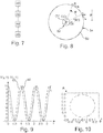
- the figure 7 schematically represents an example of a method for monitoring the object 2 to detect a difference between its trajectory and a predefined reference trajectory. This method is advantageously implemented by the unit 10.
- a reference trajectory is acquired automatically.
- This reference trajectory is a predefined setpoint trajectory that the object 2 is supposed to follow during its displacement. For example, this reference trajectory has previously been determined by applying the method of the figure 3 .
- the object 2 is set in motion and its trajectory is determined as the displacement, by applying the steps 20 to 26 previously described.
- a gap is measured between the determined trajectory and the reference trajectory.
- Step 44 is here repeated during the displacement, for example as the trajectory is determined during step 42.
- a so-called "safety zone” zone which extends radially is defined. around the reference path with a predefined distance.
- the safety zone is a cylinder of predefined radius (this radius corresponds to the safety threshold), the main axis of the cylinder being the reference trajectory. The determined trajectory is said to deviate from the reference trajectory if it leaves outside the safety zone.
- an alarm signal is emitted during a step 46 by the unit 10, this alarm signal not being emitted if this difference is less than or equal to the predetermined value.
- the figure 8 discloses a wheel 50, having a hub 52 and a circular periphery 54 centered on a center O.
- the wheel 50 is for example a bicycle wheel rotatably mounted on a fixed armature.
- the object 2 whose trajectory is to be determined consists of 4 and 6 and is fixed at the periphery 54 of the wheel 30.
- the aim here is to detect a possible deformation of the trajectory of the wheel 50 during its operation that would be due to, for example, an anomaly of the rotation (for example due to the wear of the hub and / or the support of the fixed armature).
- the wheel 50 here has a radius R equal to 30cm.
- An orthonormal coordinate system OXYZ of the space centered at the point O and having axes OX, OY and OZ is defined.
- the axes OX, OZ extend in the plane of the wheel 50.
- the axis OZ is here parallel and opposite direction to the direction of the earth's gravitational field, noted g.
- the axis OX extends horizontally.
- the wheel 50 rotates about the axis OY, perpendicular to the axes OX and OZ.
- this speed it is not necessary that this speed be constant.
- the sensors 4, 6 each comprise a mono-axial accelerometer whose measuring direction is tangent to the periphery 54 at the measuring point of this sensor.
- these accelerometers are MS9002 accelerometers from Safran-Colibrys (France).
- the data measured by these accelerometers are transmitted to the unit 10 (not shown) for recording.
- ⁇ (t) ⁇ * t the angle between the axis OX and the straight line connecting the center O to the measuring point of the sensor 4, and ⁇ the angle between the straight lines connecting the center O to the measuring points of the sensors, respectively, 4 and 6.
- This angle ⁇ is here equal to about 0.67 rad.
- the sensors 4 and 6 each measure a single physical quantity, which is the projection of the gravitational acceleration component according to the measurement direction of this sensor plus its own acceleration in the OXYZ frame.
- M A (t) g * cos ( ⁇ * t)
- M B (t) g * cos ( ⁇ * t + ⁇ )
- g 9,81m / s 2 .
- the attitude information of the object 2 is obtained from the sensors 4 and 6.
- the sensor 4 thus plays the role of the central unit. 8 and therefore there is no need to use a separate central 8.
- the figure 9 illustrates the evolution of the measured quantities M A (t) (curve 60) and M B (t) (curve 62) respectively by the sensors 4, 6, during a measurement period of 5 seconds.
- the abscissa expresses the duration (in seconds)
- the ordinate expresses the acceleration value measured by each sensor (in m / s 2 ).
- step 22 make it possible to determine the reference instants from the data of the figure 9 .
- a duration T equal to 1s is chosen.
- the trajectory is reconstructed from, for each reference instant, curvilinear abscissa values (that is, the accumulated distance D tot traveled by the point A since t 0 ) and tangent (obtained here directly from the measurement of the sensor 4).
- the figure 10 illustrates the portion of the trajectory of point A reconstructed from the data of the figure 9 at the end of the process.
- the ordinate axis indicates the evolution of the angle ⁇
- the abscissa indicates the curvilinear distance traveled by the point A when the wheel rotates.
- the detection of a deviation can be done directly on the angles reconstructed with the central unit 8.
- the knowledge of a reference trajectory enables to deduce the reference angles as a function of the curvilinear abscissa. These are used to calculate a deviation with the reconstructed angles via this process.
- Object 2 may be different.
- it may be a road or rail vehicle, an inspection probe, a moving mechanical part.
- the sensors 4 and 6 are mechanically connected to present the same attitude for the same curvilinear abscissa on the trajectory.
- the method can be used in the field of oil exploration and prospecting to determine the path of a pipe or a hose.
- the object 2 is then integral with this conduct.
- the spatial frequency F is of the order of 1 Hz or 10 Hz.
- the method can be used in a "ferris wheel” type carousel (to follow the proper rotation of the carousel), or "roller coaster” type, to follow the trajectory of wagons running on one or more rails of this ride.
- the object 2 is for example a pair of wagons coupled together. One seeks for example to check that these two cars follow the same trajectory.
- the frequency F depends in particular on the diameter of the loops (or “loops" in English) that the rim or rails of the carousel. For example, this diameter is between 5m and 50m.
- the method can be used in a cable transport type "cable car", “chairlift” or “gondola” to follow the evolution over time of the deformed (shape) of the carrier cable.
- Information on the evolution of the deformation of this cable is interesting for the monitoring of its state of health (traditional result of structural monitoring).
- the reference trajectory may therefore have been determined differently. It depends in particular on the nature of the object 2 and the context in which it is brought to evolve during its displacement. For example, if the object 2 is a vehicle guided by a rail, then the reference trajectory is that of this rail.
- Step 44 can be omitted.
- the reference trajectory can be acquired solely to determine the value of D, from the Shannon conditions applied to the reference trajectory.
- the reconstruction of the trajectory can be carried out in real time as the object 2 is moved.
- the instants t i are calculated during the displacement.
- the trajectory TR is then constructed in successive increments as the instants t i are calculated.
- the steps 22 to 26 are therefore performed alternately and incrementally until the end of the displacement.
- the order of the steps in the process of figure 7 is then modified, in particular to measure a deviation of the determined trajectory relative to the reference trajectory as the determined trajectory is constructed step by step.
- the central unit 8 can measure the attitude of the object 2 only when a reference time has been determined.
- the correlation can be calculated differently. Other functions can be used to calculate the correlation ⁇ .
- the unit 10 can be made differently.
- the interface 16 may be different (serial link, USB, wireless, etc.).
- Unit 10 can be For example, it is remote from this object 2 and collects the data measured by the remote sensors by means of the interface 16.
- the values of the duration T may be different. For example, a particular value of the duration T is defined for each of the N physical variables. The same goes for the threshold S.
- the step 24 of searching for correlations is carried out differently.
- the value of the offset dt can be calculated by means of a Kalman filter, so as to take into account the values of the offsets dt calculated for the previous reference times, which makes it possible to refine the accuracy of the measurement. and to avoid abrupt variations in time.
Landscapes
- Engineering & Computer Science (AREA)
- Physics & Mathematics (AREA)
- General Physics & Mathematics (AREA)
- Radar, Positioning & Navigation (AREA)
- Remote Sensing (AREA)
- Automation & Control Theory (AREA)
- Multimedia (AREA)
- Length Measuring Devices With Unspecified Measuring Means (AREA)
Claims (13)
- Verfahren zur Bestimmung der Bewegungsbahn eines beweglichen Objekts, dadurch gekennzeichnet, dass es umfasst:- die Bereitstellung eines beweglichen Objekts (2), umfassend erste (4) und zweite Sensoren (6), die mechanisch miteinander verbunden und eingerichtet sind, um mindestens eine selbe physikalische Größe an verschiedenen Punkten des Objekts zu messen,- die Verlagerung (20) der ersten und zweiten Sensoren entlang einer selben Bewegungsbahn (TR), wobei die ersten und zweiten Sensoren zueinander ein konstante Distanz D bis auf 2 % während der Verlagerung bewahren, wobei die Distanz D als die gekrümmte Abszisse, die die ersten und zweiten Sensoren trennt, gemessen entlang der Bewegungsbahn, definiert ist;- während der Verlagerung das Messen der mindestens einen selben physikalischen Größe durch die ersten und zweiten Sensoren, wobei die physikalische Größe in der Gruppe ausgewählt ist, umfassend eine Lichtstärke, ein Magnetfeld, die Beschleunigung der Schwerkraft, das elektromagnetische Feld, eine Temperatur, einen Luftdruck, eine Flugzeit, ein Bild, ein akustisches Feld, ein seismisches Feld oder eine Beschleunigung;- die Bestimmung (22) von Zeitpunkten, Referenzzeitpunkte (t) genannt, zu denen das bewegliche Objekt entlang der Bewegungsbahn eine kumulierte gekrümmte Distanz durchlaufen hat, die gleich einem ganzen Vielfachen der Distanz D ist, wobei diese Bestimmung für die mindestens eine selbe gemessene physikalische Größe die Suche nach einer Korrelation zwischen der zeitlichen Entwicklung dieser physikalischen Größe, die von jedem der ersten bzw. zweiten Sensoren gemessen wird, umfasst;- die Berechnung (24) einer die Bewegungsbahn des Objekts tangierenden Richtung im Bereich eines selben Sensors unter den ersten oder zweiten Sensoren für jeden der bestimmten Zeitpunkte t;- die automatische Wiederherstellung (26) der von dem beweglichen Objekt bei seiner Verlagerung verfolgten Bewegungsbahn mit Hilfe einer Interpolation, für jeden bestimmten Referenzzeitpunkt, auf Basis von:• der kumulierten gekrümmten Distanz zu diesem Referenzzeitpunkt entlang der Bewegungsbahn, und• der für diesen Referenzzeitpunkt berechneten Tangente.
- Verfahren nach Anspruch 1, bei dem die Bestimmung der Referenzzeitpunkte nach und nach für aufeinanderfolgende Zeitpunkte erfolgt und die Bestimmung eines Zeitpunkts ti auf Basis eines bekannten Zeitpunkts ti-1 umfasst, wobei die Zeitpunkte ti und ti-1 zwei aufeinanderfolgende Referenzzeitpunkte bezeichnen, wobei der Index i eine natürliche ganze Zahl ist, wobei diese Bestimmung für die mindestens eine physikalische Größe umfasst:- die automatische Berechnung einer Korrelation zwischen den Werten der mindestens einen physikalischen Größe, die von jedem der ersten und zweiten Sensoren mit der Zeit gemessen wird, über ein Probenahmezeitintervall, das zum Zeitpunkt ti-i beginnt und eine Dauer T aufweist;- die automatische Berechnung einer Zeitverschiebung dt zwischen einerseits dem Zeitpunkt, zu dem die Korrelationsfunktion ein Maximum in dem Intervall [-T, T] aufweist, und andererseits dem Ursprung des Intervalls [-T, T);- dann die Berechnung des Werts des Zeitpunkts ti, bestimmt mit Hilfe der Formel ti = ti-1 + dt.
- Verfahren nach Anspruch 2, bei dem:- die ersten (4) und zweiten Sensoren (6) eingerichtet sind, um N physikalische Größen zu messen, wobei N eine ganze Zahl größer als zwei ist;- die Bestimmung der Referenzzeitpunkte umfasst:- für jede der N physikalischen Größen die automatische Berechnung der Korrelationsfunktion und die automatische Berechnung der Zeitverschiebungen dt auf Basis der jeweiligen Korrelationsfunktion,- dann die Berechnung der durchschnittlichen Verschiebung dtmoy, der als der Durchschnitt der berechneten Zeitverschiebungen dt definiert ist, wobei der bestimmte Wert des Zeitpunkts ti durch die Formel ti = ti-1 + dtmoy gegeben ist.
- Verfahren nach Anspruch 3, bei dem:- für jede der N physikalischen Größen der Verschiebung dt nur berechnet wird, wenn der Wert der berechneten Korrelationsfunktion größer als eine vordefinierte Schwelle ist, und andernfalls nicht berechnet wird;- der Durchschnitt der Zeitverschiebungen nur aus den berechneten Verschiebungen dt erstellt wird.
- Verfahren nach einem der vorhergehenden Ansprüche, bei dem die Messung der Tangentialrichtung mit Hilfe einer Lagesteuerungsbaugruppe (8), die dem Objekt angehört, erfolgt.
- Verfahren nach einem der vorhergehenden Ansprüche, bei dem die physikalische Größe eine Größe ist, die die Position des Sensors in Bezug zu einem vordefinierten Bezugspunkt im Raum, wie einem Neigungs- oder Rotationswinkel, wiederspiegelt.
- Verfahren nach einem der vorhergehenden Ansprüche, umfassend für jeden der bestimmten Zeitpunkte t die Berechnung des Serret-Frenet-Bezugspunktes, der der berechneten Tangentialrichtung zugeordnet ist, und bei dem die automatische Wiederherstellung der Bewegungsbahn ferner auf Basis des Bezugspunktes interpoliert wird.
- Verfahren nach einem der vorhergehenden Ansprüche, bei dem sich das bewegliche Objekt (2) auf einer Oberfläche verlagert.
- Verfahren nach einem der vorhergehenden Ansprüche, bei dem die ersten (4) und zweiten (6) Sensoren mechanisch verbunden sind, um dieselbe Lage für eine selbe gekrümmte Abszisse auf der Bewegungsbahn aufzuweisen.
- Verfahren zur Erfassung einer Abweichung zwischen der Bewegungsbahn eines beweglichen Objekts und einer Referenzbahn, umfassend:- die Erfassung (40) einer Referenzbahn, der das Objekt bei seiner Verlagerung folgen soll;- die Bestimmung (42) der Bewegungsbahn, die von dem Objekt bei seiner Verlagerung verfolgt wird;- den Vergleich (44) der bestimmten Bewegungsbahn mit der Referenzbahn;- das Senden (46) eines Warnsignals, wenn eine Abweichung größer als ein vorbestimmter Wert zwischen der bestimmten Bewegungsbahn und der Referenzbahn erfasst wird, wobei im umgekehrten Fall kein Warnsignal gesandt wird; wobei dieses Verfahren dadurch gekennzeichnet ist, dass die Bestimmung der Bewegungsbahn des Objekts nach einem der vorhergehenden Ansprüche erfolgt.
- Verfahren nach Anspruch 10, bei dem die Distanz D unbedingt geringer als 2*F ist, wobei F die Raumfrequenz der Winkelfunktionen ist, die die Tangente an die Referenzbahn definierten.
- Aufzeichnungsträger von Informationen (12), dadurch gekennzeichnet, dass er Anweisungen für den Einsatz eines Verfahrens zur Bewertung der Daten, die von einem beweglichen Objekt, umfassend zwei Sensoren, die mit einer konstanten Distanz zwischen ihnen mechanisch verbunden sind, geliefert werden, auf einem elektronischen Rechner umfasst, gemäß einem Verfahren nach einem der vorhergehenden Ansprüche.
- Elektronischer Rechner (10) für den Einsatz eines Verfahrens zur Bewertung der Daten, die von einem beweglichen Objekt, umfassend zwei Sensoren, geliefert werden, gemäß einem Verfahren nach einem der Ansprüche 1 bis 11, dadurch gekennzeichnet, dass er programmiert ist, um:- Zeitpunkte, Referenzzeitpunkte (t) genannt, zu bestimmen, zu denen ein bewegliches Objekt (2), umfassend erste (4) und zweite Sensoren (6):• die mechanisch miteinander verbunden sind,• die eingerichtet sind, um mindestens eine selbe physikalische Größe an unterschiedlichen Punkten des Objekts zu messen, und• die eine konstante Distanz D zueinander bis auf 2 % während der Verlagerung bewahren, wobei die Distanz D als die gekrümmte Abszisse, die die Sensoren trennt, definiert ist,eine kumulierte gekrümmte Distanz, die gleich einem ganzen Vielfachen der Distanz D ist, entlang der Bewegungsbahn durchlaufen hat, wobei diese Bestimmung für die mindestens eine selbe gemessene physikalische Größe die Suche nach einer Korrelation zwischen der zeitlichen Entwicklung dieser physikalischen Größe, die von jedem der ersten bzw. zweiten Sensoren gemessen wird, umfasst;- eine Tangentialrichtung zur Bewegungsbahn des Objekts im Bereich eines selben Sensors unter dem ersten und zweiten Sensor für jeden der bestimmten Zeitpunkte t zu berechnen;- automatisch die von dem beweglichen Objekt bei seiner Verlagerung verfolgte Bewegungsbahn wiederherzustellen (26), mit Hilfe einer Interpolation für jeden bestimmten Referenzzeitpunkt auf Basis:• der kumulierten gekrümmten Distanz zu diesem Referenzzeitpunkt entlang der Bewegungsbahn, und• der für diesen Referenzzeitpunkt berechneten Tangente.
Applications Claiming Priority (2)
| Application Number | Priority Date | Filing Date | Title |
|---|---|---|---|
| FR1461695A FR3029281B1 (fr) | 2014-12-01 | 2014-12-01 | Procede et calculateur electronique pour determiner la trajectoire d’un objet mobile |
| PCT/FR2015/053255 WO2016087755A1 (fr) | 2014-12-01 | 2015-11-30 | Procede et calculateur electronique pour determiner la trajectoire d'un objet mobile |
Publications (2)
| Publication Number | Publication Date |
|---|---|
| EP3227635A1 EP3227635A1 (de) | 2017-10-11 |
| EP3227635B1 true EP3227635B1 (de) | 2018-12-26 |
Family
ID=52692781
Family Applications (1)
| Application Number | Title | Priority Date | Filing Date |
|---|---|---|---|
| EP15808765.0A Active EP3227635B1 (de) | 2014-12-01 | 2015-11-30 | Verfahren und elektronischer rechner zur bestimmung der bewegungsbahn eines sich bewegenden objekts |
Country Status (4)
| Country | Link |
|---|---|
| US (1) | US10571265B2 (de) |
| EP (1) | EP3227635B1 (de) |
| FR (1) | FR3029281B1 (de) |
| WO (1) | WO2016087755A1 (de) |
Families Citing this family (5)
| Publication number | Priority date | Publication date | Assignee | Title |
|---|---|---|---|---|
| CN110998229A (zh) * | 2017-07-31 | 2020-04-10 | 三菱电机株式会社 | 构造物测量装置、测量点校正装置及测量点校正方法 |
| US11718300B2 (en) * | 2019-02-27 | 2023-08-08 | Zf Automotive Germany Gmbh | Method and control unit for a system for controlling a motor vehicle |
| US11753006B2 (en) | 2020-06-08 | 2023-09-12 | Robert Bosch Gmbh | Representing objects in a surrounding environment of a vehicle using a frenet coordinate system |
| US11577733B2 (en) * | 2020-09-30 | 2023-02-14 | GM Global Technology Operations LLC | Efficient road coordinates transformations library |
| CN119354285A (zh) * | 2024-12-27 | 2025-01-24 | 上海瑞起测控科技有限公司 | 一种环境试验仓干湿球温湿度巡检记录仪巡检测量方法 |
Family Cites Families (11)
| Publication number | Priority date | Publication date | Assignee | Title |
|---|---|---|---|---|
| AU533909B2 (en) * | 1980-10-23 | 1983-12-15 | Sundstrand Data Control, Inc. | Bore-hole survey apparatus |
| US4536763A (en) * | 1981-11-09 | 1985-08-20 | Siemens Aktiengesellschaft | On-board orientation device for aircraft |
| US5064006A (en) * | 1988-10-28 | 1991-11-12 | Magrange, Inc | Downhole combination tool |
| US6405136B1 (en) * | 1999-10-15 | 2002-06-11 | Schlumberger Technology Corporation | Data compression method for use in wellbore and formation characterization |
| US6618674B2 (en) * | 2001-07-31 | 2003-09-09 | Schlumberger Technology Corporation | Method and apparatus for measurement alignment |
| DE102004030752A1 (de) * | 2004-06-25 | 2006-01-19 | Robert Bosch Gmbh | Verfahren und Vorrichtung zur Kursprädikation bei Kraftfahrzeugen |
| FR2883073B1 (fr) | 2005-03-09 | 2009-07-10 | Commissariat Energie Atomique | Procede et dispositif d'acquisition d'une forme geometrique. |
| FR2906025B1 (fr) | 2006-09-14 | 2009-04-03 | Commissariat Energie Atomique | Procede et dispositif d'acquisition d'une forme geometrique deformable |
| US20080195316A1 (en) * | 2007-02-12 | 2008-08-14 | Honeywell International Inc. | System and method for motion estimation using vision sensors |
| US8783382B2 (en) * | 2009-01-15 | 2014-07-22 | Schlumberger Technology Corporation | Directional drilling control devices and methods |
| US9027670B2 (en) * | 2012-06-21 | 2015-05-12 | Schlumberger Technology Corporation | Drilling speed and depth computation for downhole tools |
-
2014
- 2014-12-01 FR FR1461695A patent/FR3029281B1/fr not_active Expired - Fee Related
-
2015
- 2015-11-30 WO PCT/FR2015/053255 patent/WO2016087755A1/fr not_active Ceased
- 2015-11-30 EP EP15808765.0A patent/EP3227635B1/de active Active
- 2015-11-30 US US15/532,438 patent/US10571265B2/en active Active
Non-Patent Citations (1)
| Title |
|---|
| None * |
Also Published As
| Publication number | Publication date |
|---|---|
| FR3029281A1 (fr) | 2016-06-03 |
| WO2016087755A1 (fr) | 2016-06-09 |
| FR3029281B1 (fr) | 2018-06-15 |
| US20170268873A1 (en) | 2017-09-21 |
| US10571265B2 (en) | 2020-02-25 |
| EP3227635A1 (de) | 2017-10-11 |
Similar Documents
| Publication | Publication Date | Title |
|---|---|---|
| EP3227635B1 (de) | Verfahren und elektronischer rechner zur bestimmung der bewegungsbahn eines sich bewegenden objekts | |
| EP1593532B1 (de) | System zur Steuerung des Reifenfülldrucks von Kraftfahrzeugrädern | |
| EP2710334B1 (de) | Verfahren zur kalibrierung einer inerten anordnung mit einer dynamischen phasen zwischen zwei statischen phasen | |
| EP2718670B1 (de) | Vereinfachtes verfahren zur schätzung der ausrichtung eines objekts und lagesensor zur durchführung dieses verfahrens | |
| FR2531482A1 (fr) | Instrument, et notamment sonde, de mesure et de controle de sondages | |
| EP2439541B1 (de) | System zur Bestimmung der Luftgeschwindigkeit eines Flugzeugs | |
| EP3209993B1 (de) | Verfahren und vorrichtung zur überwachung von einer flugzeugsturbineschaufel durch messung einer gleichgewichtposition | |
| EP2938965B1 (de) | Verfahren zum vergleich zweier inerter einheiten mit demselben träger | |
| EP2494366B1 (de) | System und verfahren zur zählung der richtungsänderungen einer person | |
| FR2739183A1 (fr) | Systeme de determination dynamique de la position et de l'orientation d'un reseau remorque | |
| FR3090893A1 (fr) | Procede et systeme de mesure de la vitesse d’un porteur par rapport au sol | |
| EP3523602B1 (de) | System zur messung des abstands eines hindernisses durch optischen fluss | |
| EP3709049A1 (de) | Radardaten-verarbeitungssystem und entsprechendes verfahren zur geräuschdämpfung | |
| WO2020025342A1 (fr) | Procédé d'estimation du rayon extérieur d'un pneumatique équipant une roue d'un véhicule automobile | |
| FR2951535A1 (fr) | Procede de detection de mouvements parasites lors de l'alignement d'une centrale inertielle | |
| EP3006897B1 (de) | Navigationsverfahren eines fahrzeugs, navigationsvorrichtung und fahrzeug für die umsetzung dieses verfahrens | |
| EP3899432B1 (de) | Verfahren zur charakterisierung eines trägheitsnavigationssystems | |
| EP2085943A1 (de) | Verfahren zu Erfassung der Bewegung eines Fahrzeugs und entsprechende Vorrichtung | |
| EP1666923A1 (de) | Verfahren zur Lokalisierung beweglicher magnetischer Ziele | |
| FR3041753B1 (fr) | Methode de determination de la surface de trainee aerodynamique d'un vehicule | |
| FR2833712A1 (fr) | Procede de localisation passive d'une cible et notamment de localisation air-air | |
| WO2019063566A1 (fr) | Procédé de détermination de la fréquence et de la phase instantanées d'un signal périodique | |
| WO2010116094A1 (fr) | Mesure du debattement d'un element en rotation | |
| FR2853221A1 (fr) | Procede et dispositif autonome pour la determination de la position relative de deux objets en mouvement, dans un plan ou dans l'espace | |
| FR2904874A1 (fr) | Procede et dispositif pour la mesure de la vitesse d'un aeronef, notamment un giravion a basse vitesse |
Legal Events
| Date | Code | Title | Description |
|---|---|---|---|
| STAA | Information on the status of an ep patent application or granted ep patent |
Free format text: STATUS: THE INTERNATIONAL PUBLICATION HAS BEEN MADE |
|
| PUAI | Public reference made under article 153(3) epc to a published international application that has entered the european phase |
Free format text: ORIGINAL CODE: 0009012 |
|
| STAA | Information on the status of an ep patent application or granted ep patent |
Free format text: STATUS: REQUEST FOR EXAMINATION WAS MADE |
|
| 17P | Request for examination filed |
Effective date: 20170524 |
|
| AK | Designated contracting states |
Kind code of ref document: A1 Designated state(s): AL AT BE BG CH CY CZ DE DK EE ES FI FR GB GR HR HU IE IS IT LI LT LU LV MC MK MT NL NO PL PT RO RS SE SI SK SM TR |
|
| AX | Request for extension of the european patent |
Extension state: BA ME |
|
| DAV | Request for validation of the european patent (deleted) | ||
| DAX | Request for extension of the european patent (deleted) | ||
| GRAP | Despatch of communication of intention to grant a patent |
Free format text: ORIGINAL CODE: EPIDOSNIGR1 |
|
| STAA | Information on the status of an ep patent application or granted ep patent |
Free format text: STATUS: GRANT OF PATENT IS INTENDED |
|
| INTG | Intention to grant announced |
Effective date: 20180716 |
|
| GRAS | Grant fee paid |
Free format text: ORIGINAL CODE: EPIDOSNIGR3 |
|
| GRAA | (expected) grant |
Free format text: ORIGINAL CODE: 0009210 |
|
| STAA | Information on the status of an ep patent application or granted ep patent |
Free format text: STATUS: THE PATENT HAS BEEN GRANTED |
|
| AK | Designated contracting states |
Kind code of ref document: B1 Designated state(s): AL AT BE BG CH CY CZ DE DK EE ES FI FR GB GR HR HU IE IS IT LI LT LU LV MC MK MT NL NO PL PT RO RS SE SI SK SM TR |
|
| REG | Reference to a national code |
Ref country code: GB Ref legal event code: FG4D Free format text: NOT ENGLISH |
|
| REG | Reference to a national code |
Ref country code: CH Ref legal event code: EP |
|
| REG | Reference to a national code |
Ref country code: AT Ref legal event code: REF Ref document number: 1082022 Country of ref document: AT Kind code of ref document: T Effective date: 20190115 |
|
| REG | Reference to a national code |
Ref country code: DE Ref legal event code: R096 Ref document number: 602015022502 Country of ref document: DE |
|
| REG | Reference to a national code |
Ref country code: IE Ref legal event code: FG4D Free format text: LANGUAGE OF EP DOCUMENT: FRENCH |
|
| PG25 | Lapsed in a contracting state [announced via postgrant information from national office to epo] |
Ref country code: FI Free format text: LAPSE BECAUSE OF FAILURE TO SUBMIT A TRANSLATION OF THE DESCRIPTION OR TO PAY THE FEE WITHIN THE PRESCRIBED TIME-LIMIT Effective date: 20181226 Ref country code: LV Free format text: LAPSE BECAUSE OF FAILURE TO SUBMIT A TRANSLATION OF THE DESCRIPTION OR TO PAY THE FEE WITHIN THE PRESCRIBED TIME-LIMIT Effective date: 20181226 Ref country code: NO Free format text: LAPSE BECAUSE OF FAILURE TO SUBMIT A TRANSLATION OF THE DESCRIPTION OR TO PAY THE FEE WITHIN THE PRESCRIBED TIME-LIMIT Effective date: 20190326 Ref country code: BG Free format text: LAPSE BECAUSE OF FAILURE TO SUBMIT A TRANSLATION OF THE DESCRIPTION OR TO PAY THE FEE WITHIN THE PRESCRIBED TIME-LIMIT Effective date: 20190326 Ref country code: LT Free format text: LAPSE BECAUSE OF FAILURE TO SUBMIT A TRANSLATION OF THE DESCRIPTION OR TO PAY THE FEE WITHIN THE PRESCRIBED TIME-LIMIT Effective date: 20181226 Ref country code: HR Free format text: LAPSE BECAUSE OF FAILURE TO SUBMIT A TRANSLATION OF THE DESCRIPTION OR TO PAY THE FEE WITHIN THE PRESCRIBED TIME-LIMIT Effective date: 20181226 |
|
| REG | Reference to a national code |
Ref country code: NL Ref legal event code: MP Effective date: 20181226 |
|
| REG | Reference to a national code |
Ref country code: LT Ref legal event code: MG4D |
|
| PG25 | Lapsed in a contracting state [announced via postgrant information from national office to epo] |
Ref country code: AL Free format text: LAPSE BECAUSE OF FAILURE TO SUBMIT A TRANSLATION OF THE DESCRIPTION OR TO PAY THE FEE WITHIN THE PRESCRIBED TIME-LIMIT Effective date: 20181226 Ref country code: GR Free format text: LAPSE BECAUSE OF FAILURE TO SUBMIT A TRANSLATION OF THE DESCRIPTION OR TO PAY THE FEE WITHIN THE PRESCRIBED TIME-LIMIT Effective date: 20190327 Ref country code: SE Free format text: LAPSE BECAUSE OF FAILURE TO SUBMIT A TRANSLATION OF THE DESCRIPTION OR TO PAY THE FEE WITHIN THE PRESCRIBED TIME-LIMIT Effective date: 20181226 Ref country code: RS Free format text: LAPSE BECAUSE OF FAILURE TO SUBMIT A TRANSLATION OF THE DESCRIPTION OR TO PAY THE FEE WITHIN THE PRESCRIBED TIME-LIMIT Effective date: 20181226 |
|
| REG | Reference to a national code |
Ref country code: AT Ref legal event code: MK05 Ref document number: 1082022 Country of ref document: AT Kind code of ref document: T Effective date: 20181226 |
|
| PG25 | Lapsed in a contracting state [announced via postgrant information from national office to epo] |
Ref country code: NL Free format text: LAPSE BECAUSE OF FAILURE TO SUBMIT A TRANSLATION OF THE DESCRIPTION OR TO PAY THE FEE WITHIN THE PRESCRIBED TIME-LIMIT Effective date: 20181226 |
|
| PG25 | Lapsed in a contracting state [announced via postgrant information from national office to epo] |
Ref country code: IT Free format text: LAPSE BECAUSE OF FAILURE TO SUBMIT A TRANSLATION OF THE DESCRIPTION OR TO PAY THE FEE WITHIN THE PRESCRIBED TIME-LIMIT Effective date: 20181226 Ref country code: CZ Free format text: LAPSE BECAUSE OF FAILURE TO SUBMIT A TRANSLATION OF THE DESCRIPTION OR TO PAY THE FEE WITHIN THE PRESCRIBED TIME-LIMIT Effective date: 20181226 Ref country code: PT Free format text: LAPSE BECAUSE OF FAILURE TO SUBMIT A TRANSLATION OF THE DESCRIPTION OR TO PAY THE FEE WITHIN THE PRESCRIBED TIME-LIMIT Effective date: 20190426 Ref country code: PL Free format text: LAPSE BECAUSE OF FAILURE TO SUBMIT A TRANSLATION OF THE DESCRIPTION OR TO PAY THE FEE WITHIN THE PRESCRIBED TIME-LIMIT Effective date: 20181226 Ref country code: ES Free format text: LAPSE BECAUSE OF FAILURE TO SUBMIT A TRANSLATION OF THE DESCRIPTION OR TO PAY THE FEE WITHIN THE PRESCRIBED TIME-LIMIT Effective date: 20181226 |
|
| PG25 | Lapsed in a contracting state [announced via postgrant information from national office to epo] |
Ref country code: EE Free format text: LAPSE BECAUSE OF FAILURE TO SUBMIT A TRANSLATION OF THE DESCRIPTION OR TO PAY THE FEE WITHIN THE PRESCRIBED TIME-LIMIT Effective date: 20181226 Ref country code: SM Free format text: LAPSE BECAUSE OF FAILURE TO SUBMIT A TRANSLATION OF THE DESCRIPTION OR TO PAY THE FEE WITHIN THE PRESCRIBED TIME-LIMIT Effective date: 20181226 Ref country code: IS Free format text: LAPSE BECAUSE OF FAILURE TO SUBMIT A TRANSLATION OF THE DESCRIPTION OR TO PAY THE FEE WITHIN THE PRESCRIBED TIME-LIMIT Effective date: 20190426 Ref country code: RO Free format text: LAPSE BECAUSE OF FAILURE TO SUBMIT A TRANSLATION OF THE DESCRIPTION OR TO PAY THE FEE WITHIN THE PRESCRIBED TIME-LIMIT Effective date: 20181226 Ref country code: SK Free format text: LAPSE BECAUSE OF FAILURE TO SUBMIT A TRANSLATION OF THE DESCRIPTION OR TO PAY THE FEE WITHIN THE PRESCRIBED TIME-LIMIT Effective date: 20181226 |
|
| REG | Reference to a national code |
Ref country code: DE Ref legal event code: R097 Ref document number: 602015022502 Country of ref document: DE |
|
| PG25 | Lapsed in a contracting state [announced via postgrant information from national office to epo] |
Ref country code: DK Free format text: LAPSE BECAUSE OF FAILURE TO SUBMIT A TRANSLATION OF THE DESCRIPTION OR TO PAY THE FEE WITHIN THE PRESCRIBED TIME-LIMIT Effective date: 20181226 Ref country code: AT Free format text: LAPSE BECAUSE OF FAILURE TO SUBMIT A TRANSLATION OF THE DESCRIPTION OR TO PAY THE FEE WITHIN THE PRESCRIBED TIME-LIMIT Effective date: 20181226 |
|
| PLBE | No opposition filed within time limit |
Free format text: ORIGINAL CODE: 0009261 |
|
| STAA | Information on the status of an ep patent application or granted ep patent |
Free format text: STATUS: NO OPPOSITION FILED WITHIN TIME LIMIT |
|
| 26N | No opposition filed |
Effective date: 20190927 |
|
| PG25 | Lapsed in a contracting state [announced via postgrant information from national office to epo] |
Ref country code: SI Free format text: LAPSE BECAUSE OF FAILURE TO SUBMIT A TRANSLATION OF THE DESCRIPTION OR TO PAY THE FEE WITHIN THE PRESCRIBED TIME-LIMIT Effective date: 20181226 |
|
| PG25 | Lapsed in a contracting state [announced via postgrant information from national office to epo] |
Ref country code: TR Free format text: LAPSE BECAUSE OF FAILURE TO SUBMIT A TRANSLATION OF THE DESCRIPTION OR TO PAY THE FEE WITHIN THE PRESCRIBED TIME-LIMIT Effective date: 20181226 |
|
| REG | Reference to a national code |
Ref country code: CH Ref legal event code: PL |
|
| PG25 | Lapsed in a contracting state [announced via postgrant information from national office to epo] |
Ref country code: MC Free format text: LAPSE BECAUSE OF FAILURE TO SUBMIT A TRANSLATION OF THE DESCRIPTION OR TO PAY THE FEE WITHIN THE PRESCRIBED TIME-LIMIT Effective date: 20181226 Ref country code: CH Free format text: LAPSE BECAUSE OF NON-PAYMENT OF DUE FEES Effective date: 20191130 Ref country code: LU Free format text: LAPSE BECAUSE OF NON-PAYMENT OF DUE FEES Effective date: 20191130 Ref country code: LI Free format text: LAPSE BECAUSE OF NON-PAYMENT OF DUE FEES Effective date: 20191130 |
|
| REG | Reference to a national code |
Ref country code: BE Ref legal event code: MM Effective date: 20191130 |
|
| PG25 | Lapsed in a contracting state [announced via postgrant information from national office to epo] |
Ref country code: IE Free format text: LAPSE BECAUSE OF NON-PAYMENT OF DUE FEES Effective date: 20191130 |
|
| PG25 | Lapsed in a contracting state [announced via postgrant information from national office to epo] |
Ref country code: BE Free format text: LAPSE BECAUSE OF NON-PAYMENT OF DUE FEES Effective date: 20191130 |
|
| PG25 | Lapsed in a contracting state [announced via postgrant information from national office to epo] |
Ref country code: CY Free format text: LAPSE BECAUSE OF FAILURE TO SUBMIT A TRANSLATION OF THE DESCRIPTION OR TO PAY THE FEE WITHIN THE PRESCRIBED TIME-LIMIT Effective date: 20181226 |
|
| PG25 | Lapsed in a contracting state [announced via postgrant information from national office to epo] |
Ref country code: MT Free format text: LAPSE BECAUSE OF FAILURE TO SUBMIT A TRANSLATION OF THE DESCRIPTION OR TO PAY THE FEE WITHIN THE PRESCRIBED TIME-LIMIT Effective date: 20181226 Ref country code: HU Free format text: LAPSE BECAUSE OF FAILURE TO SUBMIT A TRANSLATION OF THE DESCRIPTION OR TO PAY THE FEE WITHIN THE PRESCRIBED TIME-LIMIT; INVALID AB INITIO Effective date: 20151130 |
|
| PG25 | Lapsed in a contracting state [announced via postgrant information from national office to epo] |
Ref country code: MK Free format text: LAPSE BECAUSE OF FAILURE TO SUBMIT A TRANSLATION OF THE DESCRIPTION OR TO PAY THE FEE WITHIN THE PRESCRIBED TIME-LIMIT Effective date: 20181226 |
|
| PGFP | Annual fee paid to national office [announced via postgrant information from national office to epo] |
Ref country code: DE Payment date: 20241119 Year of fee payment: 10 |
|
| PGFP | Annual fee paid to national office [announced via postgrant information from national office to epo] |
Ref country code: GB Payment date: 20241120 Year of fee payment: 10 |
|
| PGFP | Annual fee paid to national office [announced via postgrant information from national office to epo] |
Ref country code: FR Payment date: 20251125 Year of fee payment: 11 |